EP1473130A1 - Fiber-reinforced composite material and method for production thereof - Google Patents
Fiber-reinforced composite material and method for production thereof Download PDFInfo
- Publication number
- EP1473130A1 EP1473130A1 EP02783766A EP02783766A EP1473130A1 EP 1473130 A1 EP1473130 A1 EP 1473130A1 EP 02783766 A EP02783766 A EP 02783766A EP 02783766 A EP02783766 A EP 02783766A EP 1473130 A1 EP1473130 A1 EP 1473130A1
- Authority
- EP
- European Patent Office
- Prior art keywords
- resin
- fiber
- composite material
- reinforced composite
- fibers
- Prior art date
- Legal status (The legal status is an assumption and is not a legal conclusion. Google has not performed a legal analysis and makes no representation as to the accuracy of the status listed.)
- Granted
Links
Images

Classifications
-
- B—PERFORMING OPERATIONS; TRANSPORTING
- B29—WORKING OF PLASTICS; WORKING OF SUBSTANCES IN A PLASTIC STATE IN GENERAL
- B29C—SHAPING OR JOINING OF PLASTICS; SHAPING OF MATERIAL IN A PLASTIC STATE, NOT OTHERWISE PROVIDED FOR; AFTER-TREATMENT OF THE SHAPED PRODUCTS, e.g. REPAIRING
- B29C70/00—Shaping composites, i.e. plastics material comprising reinforcements, fillers or preformed parts, e.g. inserts
- B29C70/04—Shaping composites, i.e. plastics material comprising reinforcements, fillers or preformed parts, e.g. inserts comprising reinforcements only, e.g. self-reinforcing plastics
- B29C70/28—Shaping operations therefor
- B29C70/54—Component parts, details or accessories; Auxiliary operations, e.g. feeding or storage of prepregs or SMC after impregnation or during ageing
-
- B—PERFORMING OPERATIONS; TRANSPORTING
- B29—WORKING OF PLASTICS; WORKING OF SUBSTANCES IN A PLASTIC STATE IN GENERAL
- B29C—SHAPING OR JOINING OF PLASTICS; SHAPING OF MATERIAL IN A PLASTIC STATE, NOT OTHERWISE PROVIDED FOR; AFTER-TREATMENT OF THE SHAPED PRODUCTS, e.g. REPAIRING
- B29C70/00—Shaping composites, i.e. plastics material comprising reinforcements, fillers or preformed parts, e.g. inserts
-
- B—PERFORMING OPERATIONS; TRANSPORTING
- B29—WORKING OF PLASTICS; WORKING OF SUBSTANCES IN A PLASTIC STATE IN GENERAL
- B29C—SHAPING OR JOINING OF PLASTICS; SHAPING OF MATERIAL IN A PLASTIC STATE, NOT OTHERWISE PROVIDED FOR; AFTER-TREATMENT OF THE SHAPED PRODUCTS, e.g. REPAIRING
- B29C70/00—Shaping composites, i.e. plastics material comprising reinforcements, fillers or preformed parts, e.g. inserts
- B29C70/003—Shaping composites, i.e. plastics material comprising reinforcements, fillers or preformed parts, e.g. inserts characterised by the matrix material, e.g. material composition or physical properties
- B29C70/0035—Shaping composites, i.e. plastics material comprising reinforcements, fillers or preformed parts, e.g. inserts characterised by the matrix material, e.g. material composition or physical properties comprising two or more matrix materials
-
- B—PERFORMING OPERATIONS; TRANSPORTING
- B29—WORKING OF PLASTICS; WORKING OF SUBSTANCES IN A PLASTIC STATE IN GENERAL
- B29K—INDEXING SCHEME ASSOCIATED WITH SUBCLASSES B29B, B29C OR B29D, RELATING TO MOULDING MATERIALS OR TO MATERIALS FOR MOULDS, REINFORCEMENTS, FILLERS OR PREFORMED PARTS, e.g. INSERTS
- B29K2995/00—Properties of moulding materials, reinforcements, fillers, preformed parts or moulds
- B29K2995/0037—Other properties
- B29K2995/0089—Impact strength or toughness
-
- Y—GENERAL TAGGING OF NEW TECHNOLOGICAL DEVELOPMENTS; GENERAL TAGGING OF CROSS-SECTIONAL TECHNOLOGIES SPANNING OVER SEVERAL SECTIONS OF THE IPC; TECHNICAL SUBJECTS COVERED BY FORMER USPC CROSS-REFERENCE ART COLLECTIONS [XRACs] AND DIGESTS
- Y10—TECHNICAL SUBJECTS COVERED BY FORMER USPC
- Y10T—TECHNICAL SUBJECTS COVERED BY FORMER US CLASSIFICATION
- Y10T428/00—Stock material or miscellaneous articles
- Y10T428/19—Sheets or webs edge spliced or joined
-
- Y—GENERAL TAGGING OF NEW TECHNOLOGICAL DEVELOPMENTS; GENERAL TAGGING OF CROSS-SECTIONAL TECHNOLOGIES SPANNING OVER SEVERAL SECTIONS OF THE IPC; TECHNICAL SUBJECTS COVERED BY FORMER USPC CROSS-REFERENCE ART COLLECTIONS [XRACs] AND DIGESTS
- Y10—TECHNICAL SUBJECTS COVERED BY FORMER USPC
- Y10T—TECHNICAL SUBJECTS COVERED BY FORMER US CLASSIFICATION
- Y10T428/00—Stock material or miscellaneous articles
- Y10T428/249921—Web or sheet containing structurally defined element or component
- Y10T428/249924—Noninterengaged fiber-containing paper-free web or sheet which is not of specified porosity
- Y10T428/249933—Fiber embedded in or on the surface of a natural or synthetic rubber matrix
- Y10T428/249937—Fiber is precoated
-
- Y—GENERAL TAGGING OF NEW TECHNOLOGICAL DEVELOPMENTS; GENERAL TAGGING OF CROSS-SECTIONAL TECHNOLOGIES SPANNING OVER SEVERAL SECTIONS OF THE IPC; TECHNICAL SUBJECTS COVERED BY FORMER USPC CROSS-REFERENCE ART COLLECTIONS [XRACs] AND DIGESTS
- Y10—TECHNICAL SUBJECTS COVERED BY FORMER USPC
- Y10T—TECHNICAL SUBJECTS COVERED BY FORMER US CLASSIFICATION
- Y10T428/00—Stock material or miscellaneous articles
- Y10T428/31504—Composite [nonstructural laminate]
Definitions
- the present invention relates to a fiber reinforced composite material suitable for lightweight high-strength structural members of, for example, aircraft and motor vehicles, and also relates to a production method thereof.
- Fiber-reinforced composite materials having resins reinforced by fibers are widely used in such fields as aircraft, motor vehicles and architecture because of their excellent lightweight and high strength properties.
- the reinforcing fibers coexist with a resin as continuous fibers having no fiber ends therein.
- the composite material contains the ends of reinforcing fibers therein.
- stress concentration occurs near the ends of reinforcing fibers, and can cause the member made from the composite material to be fractured from near the ends. If a molded composite material is fractured at or near fiber ends contained therein, the strength of the composite material becomes lower than the expected strength.
- discontinuous fibers having a fiber length of several millimeters to tens of millimeters are used as the reinforcing fibers, to facilitate the mobility and deformation of the reinforcing fibers when the composite material is produced by molding.
- the obtained composite material is called a short fiber-reinforced composite material.
- SMC sheet molding compound
- SMC sheet molding compound
- SMC is a sheet-like intermediate base material produced by arranging reinforcing fibers cut to a length of about 10 mm to about 30 mm in one direction or at random on a resin film used as a matrix resin, and further overlaying another resin film on them.
- the base sheet is placed in a mold installed in a press, pressurized and thermally cured for molding into a bonnet of a motor vehicle, or a housing member such as a bathtub.
- SMC is used when a member having a complicated shape is produced by means of molding.
- the short fiber-reinforced composite material has such disadvantages that its strength is lower than one half of the strength of a continuous fiber-reinforced composite material and that its weight is heavier than that of the continuous fiber-reinforced composite material.
- a fiber-reinforced composite material having fiber ends has a problem that since it is fractured from near the fiber ends, the intrinsic properties of the reinforcing fibers cannot be sufficiently transferred.
- the object of the invention is to provide a lightweight high-strength fiber-reinforced composite material though it contains fiber ends therein, and also to provide a production method thereof.
- a fiber-reinforced composite material of the invention for achieving the above object is as follows.
- a fiber-reinforced composite material which comprises reinforcing fibers and a matrix resin, wherein at least some of the reinforcing fibers have their fiber ends in the matrix resin (first resin), characterized in that a second resin having an elastic modulus lower than that of the matrix resin exists in contact with and only near the fiber end portions of at least some of the reinforcing fibers having fiber ends.
- an extent of existing of the second resin is in the range of 30 times to 1,000 times of a diameter of the fiber at the fiber end portion from the fiber end of the fiber end portion.
- the elongation of the second resin is higher than that of the matrix resin.
- the strength of the second resin is higher than that of the matrix resin.
- the fracture toughness value of the second resin is larger than that of the matrix resin.
- the reinforcing fibers are carbon fibers.
- the matrix resin is an epoxy resin.
- a method for producing the fiber-reinforced composite material of the invention for achieving the aforesaid object is as follows.
- a method for producing a fiber-reinforced composite material in which a fiber-reinforced composite material is produced by molding reinforcing fibers and a matrix resin, with at least some of the reinforcing fibers having their fiber end portions in the matrix resin, comprising the steps of positioning a second resin having an elastic modulus lower than that of the matrix resin in contact with and only near the fiber end portions of at least some of the reinforcing fibers having fiber ends, and subsequently molding for producing a fiber-reinforced composite material.
- the reinforcing fibers are short fibers obtained by cutting, and that the method comprises the step of letting the second resin adhere in contact with and only near the fiber end portions of the short fibers, the step of molding the short fibers having the second resin adhering thereto and the matrix resin into a sheet, and the step of pressurizing and heating the formed sheet for curing the resin.
- the reinforcing fibers are continuous fibers having cut ends
- the method comprises the step of letting the second resin adhere in contact with and only near the end portions of the cut ends of the continuous fibers, the step of forming the continuous fibers having the second resin adhering thereto, into a state suitable for a desired shape of a member, the resin transfer molding step of injecting the matrix resin into the transformed continuous fibers, and the step of curing the resin of the molded article obtained by the resin transfer molding step.
- the method comprises the step of cutting a prepreg comprising the reinforcing fibers and the matrix resin, the step of letting the second resin adhere in contact with and only near the cut end portions of the cut reinforcing fibers, the step of laminating plural sheets of the prepreg having the second resin adhering thereto, and the step of curing the resin of the laminated prepreg in an autoclave.
- the reinforcing fibers are carbon fibers.
- the matrix resin is an epoxy resin.
- a fiber-reinforced composite material 1 of the invention comprises reinforcing fibers 3, and a matrix resin 4 as a first resin, and at least some of the reinforcing fibers 3 have their fiber ends 2a in the matrix resin 4.
- a second resin 5 having an elastic modulus lower than that of the matrix resin 4 exists in contact with and only near the fiber end portions 2 of at least some of the reinforcing fibers 3 having fiber ends 2a.
- Fig. 1 shows a mode in which the second resin 5 exists at one fiber end portion 2 out of the two fiber end portions 2 existing in the composite material in the illustrated section.
- Fig. 2 shows a mode in which the second resin 5 exists at both the two fiber end portions 2 existing in the composite material 1 in the illustrated section.
- the length of the reinforcing fibers 3 having fiber ends 2a is in a range from a few millimeters to tends of millimeters.
- the reinforcing fibers 3 having fiber ends 2a are distributed regularly or at random in the matrix resin 4.
- the second resin 5 corresponds to a chemical composition covering and adhering to the tip of the matchstick.
- one matchstick is shown.
- two matchsticks facing each other are shown.
- the fiber-reinforced composite material 1 In general, if an external force (for example, a tensile force) acts on the fiber-reinforced composite material 1, a stress is transferred between the matrix resin and the reinforcing fibers 3. Though the composite material 1 has a strength that is higher than that of the matrix resin having no reinforcing fibers 3 therein, however, near the fiber ends 2a of the reinforcing fibers 3, large shearing stresses occur in the resin 4, depending on the elastic modulus of the matrix resin 4, and fracture begins from near the fiber ends 2a.
- an external force for example, a tensile force
- the stress concentration is reduced to prevent the composite material 1 from being fractured, or to retard the fracture, allowing the composite material 1 to maintain a high strength.
- the second resin 5 must exist near the fiber ends 2a where stress concentration occurs.
- FEM Finite Element Method
- the stress concentration occurred in an extent of about 30 times the fiber diameter from the fiber ends 2a in the longitudinal (axial) direction of the fibers.
- the second resin 5 exists in an extent of at least 30 times of a diameter of the fiber.
- the fiber diameter is usually in a range of 5 to 10 ⁇ m, and therefore it is preferred the length where the second resin 5 is made to adhere is in a range of 150 to 300 ⁇ m from the fiber end 2a.
- the extent where the second resin 5 exists is not more than 1,000 times of a diameter of the fiber. Furthermore, it is preferred that the extent where the second resin 5 exists occupies the surface area corresponding to 1/3 or less, more preferably 1/5 or less of the surface area of the extent where the matrix resin 4 exists, i.e., the contact area between the matrix resin 4 and the reinforcing fibers 3.
- the second resin 5 can be made to exist in the matrix resin 4, if a resin having an elastic modulus lower than that of the matrix resin is made to adhere to the fiber end portions 2 of the reinforcing fibers 3 beforehand.
- the second resin 5 can be made to exist in the matrix resin 4, if a substance capable of reacting with the matrix resin 4 for lowering the elastic modulus of the matrix resin in the portions of the reaction is made to adhere to the fiber end portions 2 of the reinforcing fibers 3 beforehand.
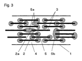
- the second resin 5 should exist independently for each of the fiber end portions 2. As indicated by the second resin 5a shown in Fig. 3, the second resin 5 can exist to cover plural fiber end portions 2 adjacent to each other. Furthermore, as indicated by second resin 5b in Fig. 3, the second resin 5 can exist to cover the fiber end portions 2 of each fiber bundle consisting of plural fibers such as a strand or roving existing as a component of the reinforcing fibers 3.
- the composite material (member) 1 can have a higher strength.
- the fracture toughness value of the second resin 5 is larger, the propagation of cracking is inhibited even if cracking occurs. As a result, the durability including fatigue resistance of the member 1 can be improved.
- the reinforcing fibers 3 can be any fibers, if they are fibers having a high strength and a high elastic modulus.
- the reinforcing fibers 3 include inorganic fibers such as glass fibers, carbon fibers, alumina fibers and ceramic fibers, metallic fibers such as steel wires and copper wires, organic fibers such as aramid fibers ("Kevlar” (trademark), “Twaron” (trademark)), PBO (Poly(p-phenylene-2, 6-benzobisoxazole)) fibers, and ultra-drawn polyethylene fibers ("Spectra” (trademark), "Dyneema” (trademark)), and mixed fibers of these inorganic, metallic and organic fibers.
- inorganic fibers such as glass fibers, carbon fibers, alumina fibers and ceramic fibers
- metallic fibers such as steel wires and copper wires
- organic fibers such as aramid fibers ("Kevlar” (trademark), “Twaron”
- carbon fibers are excellent in strength and elastic modulus. Therefore, including at least carbon fibers in the reinforcing fibers 3 is most preferred, since the composite material 1 can have a lighter weight and a higher strength. In the case where the composite material is applied as a member for a motor vehicle, aircraft or the like, it is preferred that the carbon fibers have an elastic modulus of 200 to 600 GPa and a strength of 3.5 to 6.0 GPa.
- Glass fibers are also excellent in cost performance and desirable as the reinforcing fibers for automobile members and architectural members in need of cost reduction.
- the reinforcing fibers 3 can be provided in any of various modes, for example, as a strand or roving formed by paralleling continuous fibers or discontinuous fibers (short fibers) in one direction, cloth such as woven fabric or mat, braids, unidirectional, bi-directional, random, pseudo-isotropic or three-dimensionally dispersed mat-like material, heterogeneous lattice or mesh material, three-dimensional material such as triaxially woven fabric, etc.
- An especially preferred mode of reinforcing fibers for a complicatedly shaped member as used in a motor vehicle is short fibers having a length of 5 to 30 mm. These short fibers can be oriented regularly in one direction, two directions, pseudo-isotropic manner, or at random in a highly rugged place.
- a unidirectional material comprising continuous fibers or a woven fabric is the most suitable reinforcing fibers.
- a woven fabric once cut is used.
- usable is a woven fabric partially hollowed out and having another woven fabric joined or overlapped in the hollowed-out portion, or a woven fabric having a mat of short fibers added or covered with a patch in the hollowed-out portion.
- the member is used in a motor vehicle or aircraft, it is preferred that at least 25% of the reinforcing fibers are arranged in the direction in which the strength is needed, since the strength can be improved.
- the matrix resin examples include thermosetting resins such as epoxy resins, polyester resins, vinyl ester resins, phenol resins and urethane resins, thermoplastic resins such as polyamides (nylons), polyphenylene sulfide (PPS), polyethylene, polypropylene (PP), polystyrene, acrylonitrile styrene butadiene copolymer (ABS), polyvinyl chloride, polycarbonates, polyethylene terephthalate (PET), polybutylene terephthalate (PBT), and styrene acrylonitrile copolymer, alloy resins obtained by mixing these resins, modified resins, etc.
- thermosetting resins such as epoxy resins, polyester resins, vinyl ester resins, phenol resins and urethane resins
- thermoplastic resins such as polyamides (nylons), polyphenylene sulfide (PPS), polyethylene, polypropylene (PP), polystyrene, acrylon
- thermoplastic resin such as a nylon or polypropylene is preferred. Since a thermoplastic resin also allows easy recycling, it is suitable also for mass-produced members such as parts of general motor vehicles.
- the elastic modulus of the matrix resin 4 also affects the stress transfer to the reinforcing fibers 3. If the elastic modulus is higher, a larger stress can be transferred.
- the elastic modulus is in a range from 1.5 to 7 GPa. A more preferred range is from 3 to 5 GPa.
- the elastic modulus of the matrix resin 4 can be measured according to JIS K 7113 or the nano-indentation method described later.
- the elongation of the matrix resin 4 is higher than that of the reinforcing fibers 3, since the composite material 1 can have a higher strength. If the matrix resin 4 is fractured before the reinforcing fibers 3, the stress cannot be transferred, and the strength declines. It is preferred that the elongation of the matrix resin 4 is in a range from about 1.2 to about 10 times the elongation of the reinforcing fibers 3. The elongation of the matrix resin 4 can be higher than the upper limit value, but it is wasteful, since the reinforcing fibers 3 are fractured before the matrix resin 4 is elongated to such a level. The elongation and strength of a resin are measured according to JIS K 7113 or ASTM D638.
- the fracture toughness value of the second resin 5 is larger than that of the matrix resin 4, since the fracture near the fiber end portions 2 where the second resin 5 exists can be retarded to also retard the fracture of the member 1. As a result, the strength of the member 1 can be further improved.
- the fracture toughness value of the second resin 5 is not lower than 1.3 times the fracture toughness value of the matrix resin 4. More particularly, the fracture toughness value of the second resin 5 is 100 J/m 2 or more, more preferably 150 J/m 2 or more.
- the fracture toughness value of a resin is measured based on ASTM E399 (Compact Test Standard) .
- the fracture toughness value is also called the energy release rate (G1c).
- the fracture toughness value refers to a value relating to the resistance force of a resin against crack propagation.
- Methods for enhancing the elastic modulus and elongation of the matrix resin 4 include alloying techniques such as blending a thermoplastic resin with a thermosetting resin, and resin modification techniques such as adding a rubber to a thermosetting resin. Furthermore, methods of adding carbon nano-tubes, filler such as clay mineral or ceramic particles such as silica particles or silicon carbide particles to a resin also allow the elastic modulus and elongation of the matrix resin to be adjusted.
- Fibers preferred as the reinforcing fibers 3 are carbon fibers or glass fibers that have such brittleness as to allow fiber ends 2a to be easily formed by cutting. Above all, carbon fibers having the strength of 3 to 6 GPa are preferred to obtain a lightweight high-strength member 1.
- the strength, elastic modulus and elongation of fibers can be measured according to JIS R 7601.
- the diameter of fibers is measured at a magnification of 1,000 times using an electron microscope. An optical microscope can also be used similarly for measuring the diameter. The diameter can also be calculated from the circular section assumed from the weight of the fibers per unit length and the specific gravity of the fibers.
- the fiber ends 2a of the reinforcing fibers 3 can be formed also by such a method as breaking, shaving or laser processing, in addition to by cutting.
- the fiber ends 2a can be formed by working the reinforcing fibers 3 individually or by cutting respective fiber bundles such as strands or rovings.
- the end face of each fiber end 2a can be rugged or flat.
- the end face of each fiber end 2a can be virtually perpendicular (90°) to the axial direction (longitudinal direction) of each fiber or has an angle to some extent (about 90° to about 20° to the axial direction).
- the fiber ends 2a can exist at random in the composite material 1 or regularly to some extent or as sets, as occurring when they are cut as bundles.
- the rate of the reinforcing fibers 3 having fiber ends 2a in the composite material 1 is larger if the shape of the member 1 is more complicated.
- all the reinforcing fibers 3 can have fiber ends 2a.
- the reinforcing fibers 3 having fiber ends 2a can be uniformly distributed in the member or can exist locally in complicatedly shaped portions, etc.
- the member 1 As described before, near the fiber end portions 2 of the reinforcing fibers 3 having fiber ends 2a, large shearing forces occur in the matrix resin 4, to fracture the matrix resin 4, not allowing stresses to be transferred to the fibers, and the member 1 as a whole is fractured.
- the fiber-reinforced composite material 1 of the invention since the second resin 5 having an elastic modulus lower than that of the matrix resin 4 exists near the fiber end portions 2, the fracture from near the fiber end portions 2 can be prevented or retarded.
- the member 1 has a high strength.
- the second resin 5 examples include, like the above-mentioned matrix resin 4, thermosetting resins such as epoxy resins, polyester resins, vinyl ester resins and phenol resins, thermoplastic resins such as polyamides, polyethylene, polypropylene, polystyrene, acrylonitrile styrene butadiene copolymer, polyvinyl chloride, polycarbonates, polyethylene terephthalate, polybutylene terephthalate, and styrene acrylonitrile copolymer, polymer alloys consisting of these thermoplastic resins, etc.
- thermosetting resins such as epoxy resins, polyester resins, vinyl ester resins and phenol resins
- thermoplastic resins such as polyamides, polyethylene, polypropylene, polystyrene, acrylonitrile styrene butadiene copolymer, polyvinyl chloride, polycarbonates, polyethylene terephthalate, polybutylene terephthalate, and s
- the second resin 5 can be selected from all kinds of resins, if the elastic modulus of the second resin 5 is lower than that of the matrix resin 4. It is preferred that the elastic modulus of the second resin 5 is in a range from 0.3 to 0.9 time the elastic modulus of the matrix resin 4, since the balance between the stress relaxation and the stress transfer is good.
- Methods for lowering the elastic modulus include such techniques as shortening the distance between crosslinking points in the case of an epoxy resin, and narrowing the molecular weight distribution in the case of a thermoplastic resin.
- the elastic modulus of the second resin 5 can be measured according to JIS K 7113, like that of the matrix resin 4.
- the micro-Vickers method or nano-indentation method can be used.
- the micro-Vickers method is described in JIS Z 2244 and ASTM E384. In the method, the hardnesses of the portion of the matrix resin 4 and the portion of the second resin 5 are measured, and in the case where the portion of the second resin 5 is softer, it is judged that the elastic modulus of the second resin 5 is lower.
- an instrument commercially available from, for example, Micro Photonics, USA is used to press a regular triangular pyramid-shaped indenter into the portion of the matrix resin 4 or the second resin 5, and the gradient of elastic recovery caused by unloading is used to quantitatively measure the elastic modulus.
- the second resin 5 can exist independently at the end of each single fiber (like a matchstick), or as shown in Fig. 3, the second resin can combine the fiber ends 2a of plural reinforcing fibers 3 as indicated by 5a, or can cover the entire end of a fiber bundle consisting of plural fibers such as a strand, as indicated by 5b.
- the second resin exists at the end of a strand having a width of several millimeters consisting of hundreds of to hundreds of thousands of single fibers, as indicated by 5b. The reason is that letting the second resin 5 adhere to respective fiber bundles is more efficient than letting the resin adhere to the respective fibers individually.
- the second resin 5 exists can be confirmed by observing a section of the composite material 1 using an optical microscope.
- a section of the composite material 1 is ground, and the lengths of optically differently colored portions are measured.
- the composite material is immersed in a solvent capable of dissolving the second resin 5 alone or the matrix resin 4 alone, and the resin remaining undissolved in the composite material or the resin remaining near the fiber ends 2a is observed for confirming respective sizes.
- the fiber ends 2a are irradiated with ultraviolet rays, to change the color of the epoxy portions into brown, for allowing both the resins to be easily distinguished optically, and the lengths of the adhering nylon resin can be measured.
- infrared analysis can also be used to detect a component contained in the matrix resin 4 and not contained in the second resin 5.
- the second resin 5 can be fused to the fiber end portions 2, or the second resin 5 can also be converted into a powder for allowing it to adhere to the fiber end portions 2 directly using its electrostatic or adhesive property.
- the resin destined to be the second resin 5 is made to adhere to certain length portions of reinforcing fibers or reinforcing fiber bundles in the longitudinal direction, and the fibers or fiber bundles are cut or broken at the adhering portions for obtaining fibers or fiber bundles having fiber end portions with the second resin 5 adhering to them on one side or on both sides.
- the second resin 5 can also be made to adhere to the fiber end portions 2, by applying a substance capable of reacting with the matrix resin 4 for lowering the elastic modulus of the matrix resin 4, to near the fiber end portions 2.
- a curing inhibitor or a softening agent for lowering the crosslinking density of the matrix resin 4 is applied to the fiber end portions 2 of the reinforcing fibers, to lower the elastic modulus. More particularly, in the case where the matrix resin 4 is an epoxy resin, if water is deposited at the fiber end portions 2, the curing of the epoxy resin can be inhibited, and the elastic modulus of the matrix resin in the portions near the fiber end portions 2 can be lowered compared with that of the matrix resin 4 in the other portions.
- the second resin 5 can also be applied to the fiber end portions 2 using a brush or the like. It is also desirable that the second resin 5 is adhesive and is made to adhere to the fiber end portions 2 beforehand, for preventing that the reinforcing fibers 3 are scattered due to wind or the like, or shift from predetermined positions.
- the elongation and the strength of the second resin 5 are larger, fracture can be more effectively inhibited, allowing the member 1 to have a higher strength, like the matrix resin 4. Moreover, in the case where the fracture toughness value of the second resin 5 is larger, even if a crack is formed, the propagation of the crack can be inhibited to improve durability such as fatigue resistance.
- the particular elastic modulus of the second resin 5 is in a range from 0.8 to 5 GPa. If the elastic modulus is lower than the lower limit, the stress transferred from the second resin 5 to the reinforcing fibers 3 is very small, and it can happen that the strength of the member 1 cannot be sufficiently enhanced. If the elastic modulus is higher than the upper limit, it is difficult to select the resin for the matrix resin 4, and it can happen that the cost is raised. A more preferred range of the elastic modulus of the second resin 5 is from 1.0 to 4 GPa.
- the elongation of the second resin 5 is in a range from 2 to 50%, larger than that of the reinforcing fibers 3, and that the strength of the second resin 5 is in a range from 2 to 100 MPa. If the elongation is smaller than the lower limit, it is lower than the elongation of the reinforcing fibers 3, and it can happen that the second resin 5 is fractured earlier than the reinforcing fibers 3. If the elongation is higher than the upper limit, the reinforcing fibers 3 are fractured earlier wastefully. If the strength is lower than the lower limit, it can happen that the second resin 5 is fractured earlier than the reinforcing fibers 3. If the strength is higher than the upper limit, the cost of the member 1 rises since the cost of the second resin 5 rises.
- the second resin 5 having an elastic modulus lower than that of the matrix resin 4 exists near the fiber end portions 2 of the reinforcing fibers 3 having the fiber ends 2a to relax the stress concentration, the fracture of the member 1 can be prevented or retarded, allowing the member 1 to have a high strength.
- both the second resin 5 and the matrix resin 4 are resins, the member 1 can be kept light in weight.
- the rate of the reinforcing fibers 3 having the second resin 5 adhering to near the fiber end portions 2 among the reinforcing fibers 3 having fiber ends 2a is 30% or more based on the quantity of all the reinforcing fibers 3 having the fiber ends 2a. If the rate is less than 30%, the degree in the improvement of strength is within the scope of fluctuation, and the improvement may not be able to be identified. It is more preferred that more than one half of the reinforcing fibers 3 having fiber ends 2a have the second resin 5 adhering to near their fiber end portions 2.
- the rate of the reinforcing fibers having the second resin 5 adhering to near the fiber end portions 2 among the reinforcing fiber 3 having the fiber ends 2a is 80% or more based on all the reinforcing fibers 3 having the fiber ends 2a.
- Preferred molding methods for producing the member composed of the fiber-reinforced composite material 1 of the invention include SMC (sheet molding compound) and BMC (bulk molding compound), P4 (N.G. Chavka, et al., "P4: Glass Fiber Preforming Technology for Automotive Applications,” 44th International SAMPE Symposium, May 23-27, 1999), etc.
- BMC refers to a bulk-like intermediate base material formed by mixing reinforcing fibers 3 having fiber ends 2a, cut to have a length of about 10 to about 30 mm, with a matrix resin.
- P4 is also a reinforced base material containing fibers having fiber ends 2a, with a length of 70 to 200 mm, as reinforcing fibers 3, like SMC and BMC.
- the base material allows the fibers to be controlled in orientation (for example, the fibers can be arranged in one direction), and can be used for producing a composite material having a higher strength.
- the central one ply of the seven plies was cut in the direction (width direction) perpendicular to the fiber direction of the reinforcing fibers 3 using a cutter, to form fiber ends 2a, and a second resin 5 was made to adhere to the fiber ends 2a over a length of 0.5 mm.
- the second resin 5 was a nylon resin (elastic modulus: 1.8 GPa, elongation: 40%, strength: 40 MPa, fracture toughness value: 180 J/m 2 ), and it was made to adhere to near the fiber end portions 2 in a fused state.
- a tensile specimen (width: 10 mm, length: 250 mm, thickness: 1 mm, position of fiber ends 2a: at the center in the length direction, weight: 40 g) was prepared.
- the obtained tensile specimen was used for carrying out a tensile test according to JIS K 7073.
- the specimen was tensile-tested at a tensile speed of 2 mm/min, and as a result, the tensile strength was found to be 2,500 MPa.
- the fractured state of the specimen was observed after completion of the tensile test, and the fracture state showing a broom like fracture mode that is not so greatly different from that of a continuous fiber-reinforced composite material was observed.
- the fiber-reinforced composite material had fiber ends in it, the obtained fiber-reinforced composite material had a lightweight and a high strength.
- a fiber-reinforced composite material was produced as described for Example 1, except that the fiber ends 2a formed by cutting the central one ply had no second resin 5 adhering to near the fiber end portions 2, and a tensile specimen was prepared from it similarly.
- the weight of the specimen was 40 g.
- the tensile strength was 2,310 MPa.
- the fractured state of the specimen was observed after completion of the tensile test, and found to show a fracture extending in the width direction of the specimen at the center of the specimen, i.e., at the portion where the cut fiber ends 2a existed.
- a fiber-reinforced composite material 1 was produced as described for Example 1, except that a mixture consisting of 95 parts by weight of the same epoxy resin as used in Example 1 and 5 parts by weight a polyether sulfone resin (PES) was used as the second resin 5, and that the adhering length was 0. 3 mm.
- a tensile specimen was prepared as described in Example 1. As a result of a tensile test, the strength was 2,440 MPa. The weight of the specimen was 40 g.
- the elastic modulus, elongation and strength of the second resin 5 measured according to JIS K 7113 were respectively 2.5 GPa, 5% and 60 MPa, and the fracture toughness value of the second resin 5 measured based on ASTM E399 (Compact Test Standard) was 210 J/m 2 .
- a carbon fiber bundle consisting of 240,000 carbon fibers (elastic modulus: 240 GPa, strength: 5.0 GPa, fiber diameter: 7 ⁇ m) was cut to have a length of 24 to 25 mm using a rotary cutter, to produce a short carbon fiber bundle.
- the same nylon resin (second resin 5) as used in Example 1 was made to adhere to both the ends of the obtained short carbon fiber bundle in length ranges of 0.5 to 1 mm from the fiber ends 2a in a fused state.
- the short carbon fiber bundle having the second resin 5 adhering to it was dispersed at random on a vinyl ester resin film, to produce an SMC sheet (fiber areal weight: 1,200 g/m 2 ).
- a tensile specimen (length: 250 mm, width: 25 mm) was cut out, and a tensile test was carried out according to JIS K 7073.
- the strength of the specimen was 550 MPa.
- the fractured state of the specimen was observed using an electron microscope, and as a result, it was confirmed that the respective fibers had been substantially uniformly fractured.
- An SMC sheet was produced as described for Example 3, except that nothing, i.e., no second resin was made to adhere to either end of the short carbon fiber bundle, and a box-shaped short fiber-reinforced composite material was produced by means of press molding.
- the reinforcing fibers were virtually uniformly spread as in Example 3, and a box-shaped short carbon fiber-reinforced composite material having a thickness of 1.8 to 1.9 mm was obtained.
- the specific gravity of the material was 1.55.
- Example 3 From the obtained composite material, a tensile specimen was cut out as in Example 3, and a tensile test was carried out as in Example 3. The strength of the specimen was 230 MPa. The fractured state of the specimen was observed with an SEM, and as a result, it was confirmed that the fibers had pulled out in the fractured face.
- Example 3 An SMC sheet was produced as described for Example 3, except that the same nylon resin (second resin 5) as used in Example 1 was made to adhere to only one of the ends of the cut short carbon fiber bundle, and a short carbon fiber-reinforced composite material 1 having a thickness of 1.8 mm and a specific gravity of 1.55 was obtained by means of press molding.
- the obtained composite material 1 was tensile-tested as described for Example 3, and as a result, the strength of the specimen was 400 MPa.
- the short carbon fiber bundle having the second resin 5 adhering to it obtained in Example 3 was arranged in one direction, to produce a mat (fiber areal weight 300 g/m 2 ).
- Six such mats were laminated, and impregnated with an epoxy resin by means of resin transfer molding (RTM), and the epoxy resin was cured to obtain a 2.0 mm thick short carbon fiber-reinforced composite material 1.
- the epoxy resin used as the matrix resin 4 had an elastic modulus of 3.5 GPa, a strength of 70 MPa, an elongation of 4% and a fracture toughness value of 85 J/m 2 .
- a tensile specimen (length: 250 mm, width: 25 mm) was cut out, and tensile-tested according to JIS K 7073.
- the tensile specimen had a strength of 770 MPa and a specific gravity of 1.6.
- the fractured state of the specimen was observed with an electron microscope, and as a result, it was confirmed that the fibers had not pulled out from the fractured face and had been substantially uniformly fractured.
- a model test of reinforcement of the fiber end portions 2 by the second resin 5 was carried out.
- a 12.5 mm wide, 230 mm long and 0.2 mm thick carbon fiber prepreg having carbon fibers arranged in the longitudinal direction was produced.
- Seven plies of the prepreg were laminated in the same direction. In this case, the central one ply of the seven plies was cut in the direction (width direction) perpendicular to the fiber direction at the center, and a second resin 5 having an elongation higher than that of the matrix resin (epoxy resin) 4 of the prepreg was made to adhere to the cut portions to cover the cut faces in 0.5 mm length ranges from the cut faces.
- a tensile specimen was prepared based on JIS K 7073, and a tensile test was carried out. The tensile strength was about 2,450 MPa.
- the second resin 5 used was produced by kneading 5 parts by weight of a nylon resin (elongation 250%) with 95 parts by weight of the same epoxy resin as the matrix resin 4 to have a higher elongation.
- the elongation of the matrix resin 4 was 5%, and the elongation of the second resin 5 was 15%.
- a model test of reinforcement of the fiber end portions 2 by the second resin 5 was carried.
- a 12.5 mm wide, 230 mm long and 0.2 mm thick carbon fiber prepreg with carbon fibers arranged in the longitudinal direction was produced, and seven plies of the prepreg were laminated in the same direction.
- the central one ply of the seven plies was cut in the direction (width direction) perpendicular to the fiber direction at the center, and a second resin 5 having a strength higher than that of the matrix resin (epoxy resin) 4 of the prepreg was made to adhere to the cut portions, to cover the cut faces in 0.5 mm length ranges from the cut faces.
- a tensile specimen was prepared based on JIS K 7073, and a tensile test was carried out. The tensile strength was about 2,480 MPa.
- the second resin 5 used was produced by kneading 3 parts by weight of CF milled yarns with 97 parts by weight of the same epoxy resin as the matrix resin 4, to have a higher strength.
- the matrix resin 4 had the strength of 85 MPa, and the second resin 5 had the strength of 108 MPa.
- a 12.5 mm wide, 230 mm long and 0.2 mm thick carbon fiber prepreg with carbon fibers arranged in the longitudinal direction was produced, and seven plies of the prepreg were laminated in the same direction.
- the central one ply of the seven plies was cut in the direction (width direction) perpendicular to the fiber direction at the center, and no second resin was used to reinforce the cut portions. That is, the cut portions were directly positioned in the matrix resin.
- a tensile specimen was prepared based on JIS K 7073, and a tensile test was carried out. The tensile strength was about 2,200 MPa.
- Example 6 Example 7 Comparative Example 3 Resin used for reinforcing the cut portions Amount (Parts by weight) Epoxy resin 95 Epoxy resin 97 Epoxy resin 100 Nylon resin 5 CF milled yarns 3 --- Strength (MPa) 83 108 85 Elongation (%) 15 5 5 Matrix resin Amount (parts by weight) Epoxy resin 100 Epoxy resin 100 Epoxy resin 100 Strength (MPa) 85 85 Elongation (%) 5 5 5 Tensile strength (MPa) 2,450 2,480 2,200
- the fiber-reinforced composite material of the invention has a second resin having an elastic modulus lower than that of the matrix resin adhering to at least some of the end portions of the reinforcing fibers existing in the fiber-reinforced composite material. It, therefore, has a structure to relax the stress concentration occurring near the end portions of the reinforcing fibers caused by the external forces acting on the composite material. As a result, a high-strength fiber-reinforced composite material excellent in the capability of being transformed can be provided even though it has a lightweight.
Landscapes
- Chemical & Material Sciences (AREA)
- Engineering & Computer Science (AREA)
- Composite Materials (AREA)
- Mechanical Engineering (AREA)
- Physics & Mathematics (AREA)
- Mathematical Physics (AREA)
- Reinforced Plastic Materials (AREA)
- Moulding By Coating Moulds (AREA)
- Casting Or Compression Moulding Of Plastics Or The Like (AREA)
Abstract
Description
| Example 6 | Example 7 | Comparative Example 3 | ||
| Resin used for reinforcing the cut portions | Amount (Parts by weight) | Epoxy resin 95 | Epoxy resin 97 | Epoxy resin 100 |
| Nylon resin 5 | CF milled yarns 3 | --- | ||
| Strength (MPa) | 83 | 108 | 85 | |
| Elongation (%) | 15 | 5 | 5 | |
| Matrix resin | Amount (parts by weight) | Epoxy resin 100 | Epoxy resin 100 | Epoxy resin 100 |
| Strength (MPa) | 85 | 85 | 85 | |
| Elongation (%) | 5 | 5 | 5 | |
| Tensile strength (MPa) | 2,450 | 2,480 | 2,200 |
Claims (13)
- A fiber-reinforced composite material, which comprises reinforcing fibers and a matrix resin, wherein at least some of the reinforcing fibers have their fiber ends in the matrix resin, characterized in that a second resin having an elastic modulus lower than that of the matrix resin exists in contact with and only near the fiber end portions of at least some of the reinforcing fibers having fiber ends.
- A fiber-reinforced composite material, according to claim 1, wherein an extent of existing of the second resin is in the range of 30 times to 1,000 times of a diameter of the fiber at the fiber end portions from the fiber end of the fiber end portion.
- A fiber-reinforced composite material, according to claim 2, wherein the elongation of the second resin is higher than the elongation of the matrix resin.
- A fiber-reinforced composite material, according to claim 2, wherein the strength of the second resin is higher than that of the matrix resin.
- A fiber-reinforced composite material, according to claim 2, wherein the fracture toughness value of the second resin is larger than that of the matrix resin.
- A fiber-reinforced composite material, according to claim 1, wherein the reinforcing fibers are carbon fibers.
- A fiber-reinforced composite material, according to claim 1, wherein the matrix resin is an epoxy resin.
- A method for producing a fiber-reinforced composite material, in which a fiber-reinforced composite material is produced by molding reinforcing fibers and a matrix resin, with at least some of the reinforcing fibers having their fiber end portions in the matrix resin, comprising the steps of positioning a second resin having an elastic modulus lower than that of the matrix resin in contact with and only near the fiber end portions of at least some of the reinforcing fibers having fiber ends, and subsequently molding for producing a fiber-reinforced composite material.
- A method for producing a fiber-reinforced composite material, according to claim 8, wherein the reinforcing fibers are short fibers obtained by cutting, and that the method comprises the step of letting the second resin adhere in contact with and only near the fiber end portions of the short fibers, the step of molding the short fibers having the second resin adhering thereto and the matrix resin into a sheet, and the step of pressurizing and heating the formed sheet for curing the resin.
- A method for producing a fiber-reinforced composite material, according to claim 8, wherein the reinforcing fibers are continuous fibers having cut ends, and that the method comprises the step of letting the second resin adhere in contact with and only near the end portions of the cut ends of the continuous fibers, the step of transforming the continuous fibers having the second resin adhering thereto, into a state suitable for a desired shape of a member, the resin transfer molding step of injecting the matrix resin into the transformed continuous fibers, and the step of curing the resin of the molded article obtained by the resin transfer molding step.
- A method for producing a fiber-reinforced composite material, according to claim 8, wherein the method comprises the step of cutting a prepreg comprising the reinforcing fibers and the matrix resin, the step of letting the second resin adhere in contact with and only near the cut end portions of the cut reinforcing fibers, the step of laminating plural sheets of the prepreg having the second resin adhering thereto, and the step of curing the resin of the laminated prepreg in an autoclave.
- A method for producing a fiber-reinforced composite material, according to claim 8, wherein the reinforcing fibers are carbon fibers.
- A method for producing a fiber-reinforced composite material, according to claim 8, wherein the matrix resin is an epoxy resin.
Applications Claiming Priority (5)
| Application Number | Priority Date | Filing Date | Title |
|---|---|---|---|
| JP2001372911 | 2001-12-06 | ||
| JP2001372911 | 2001-12-06 | ||
| JP2002046207 | 2002-02-22 | ||
| JP2002046207 | 2002-02-22 | ||
| PCT/JP2002/012699 WO2003047830A1 (en) | 2001-12-06 | 2002-12-04 | Fiber-reinforced composite material and method for production thereof |
Publications (3)
| Publication Number | Publication Date |
|---|---|
| EP1473130A1 true EP1473130A1 (en) | 2004-11-03 |
| EP1473130A4 EP1473130A4 (en) | 2010-07-14 |
| EP1473130B1 EP1473130B1 (en) | 2011-08-24 |
Family
ID=26624910
Family Applications (1)
| Application Number | Title | Priority Date | Filing Date |
|---|---|---|---|
| EP20020783766 Expired - Lifetime EP1473130B1 (en) | 2001-12-06 | 2002-12-04 | Fiber-reinforced composite material and method for production thereof |
Country Status (5)
| Country | Link |
|---|---|
| US (1) | US7208220B2 (en) |
| EP (1) | EP1473130B1 (en) |
| JP (1) | JP4258377B2 (en) |
| CA (1) | CA2468952C (en) |
| WO (1) | WO2003047830A1 (en) |
Cited By (4)
| Publication number | Priority date | Publication date | Assignee | Title |
|---|---|---|---|---|
| CN102926203A (en) * | 2012-11-09 | 2013-02-13 | 金发科技股份有限公司 | Sizing agent for emulsion type carbon fibers, a method for preparing the same and application |
| CN108225864A (en) * | 2018-01-19 | 2018-06-29 | 国电锅炉压力容器检验中心 | The measuring method of material elongation percentage |
| WO2019079676A1 (en) * | 2017-10-19 | 2019-04-25 | Magna Exteriors Inc. | Method of reducing knit line during compression molding of carbon fiber smc for complex 3d structural applications |
| US10400389B2 (en) | 2005-10-11 | 2019-09-03 | Board Of Trustees At Southern Illinois University | Composite friction materials having carbon nanotube and carbon nanofiber friction enhancers |
Families Citing this family (35)
| Publication number | Priority date | Publication date | Assignee | Title |
|---|---|---|---|---|
| US7505885B2 (en) * | 2003-01-24 | 2009-03-17 | The Boeing Company | Method and interface elements for finite-element fracture analysis |
| DK1791997T3 (en) * | 2004-08-31 | 2012-08-13 | Obermeyer Henry K | High Strength Connection System for Fiber Reinforced Composite Materials |
| WO2007018676A2 (en) * | 2005-05-23 | 2007-02-15 | Masonite Corporation | Polymeric door facing with textured interior surface, and method of forming same |
| US7735407B2 (en) * | 2006-07-12 | 2010-06-15 | Keener James H | Projectile resistant material |
| US8361265B2 (en) * | 2006-09-28 | 2013-01-29 | Toray Industries, Inc. | Process for producing composite prepreg base, layered base, and fiber-reinforced plastic |
| FR2907706B1 (en) * | 2006-10-26 | 2009-02-06 | Snecma Sa | PROCESS FOR MANUFACTURING A WINDOW WINDOW IN COMPOSITE MATERIAL |
| FR2907707B1 (en) * | 2006-10-26 | 2009-01-30 | Snecma Sa | PROCESS FOR MANUFACTURING A WINDOW WINDOW IN COMPOSITE MATERIAL |
| US20080145595A1 (en) * | 2006-12-14 | 2008-06-19 | Pratt Charles F | Composite pedestal base assembly |
| JP4887323B2 (en) | 2007-05-22 | 2012-02-29 | 三洋化成工業株式会社 | Fiber sizing agent |
| US8449709B2 (en) | 2007-05-25 | 2013-05-28 | The Boeing Company | Method of fabricating fiber reinforced composite structure having stepped surface |
| DE102007037649A1 (en) * | 2007-08-09 | 2009-02-12 | Airbus Deutschland Gmbh | Method for producing a component and fiber-reinforced thermoplastic component |
| US8540909B2 (en) * | 2009-03-09 | 2013-09-24 | The Boeing Company | Method of reworking an area of a composite structure containing an inconsistency |
| US8449703B2 (en) | 2009-03-09 | 2013-05-28 | The Boeing Company | Predictable bonded rework of composite structures using tailored patches |
| US9492975B2 (en) | 2009-03-09 | 2016-11-15 | The Boeing Company | Structural bonded patch with tapered adhesive design |
| US8617694B1 (en) | 2009-03-09 | 2013-12-31 | The Boeing Company | Discretely tailored multi-zone bondline for fail-safe structural repair |
| US8524356B1 (en) | 2009-03-09 | 2013-09-03 | The Boeing Company | Bonded patch having multiple zones of fracture toughness |
| US20100233424A1 (en) * | 2009-03-10 | 2010-09-16 | The Boeing Company | Composite structures employing quasi-isotropic laminates |
| US8709319B2 (en) | 2009-11-06 | 2014-04-29 | The Boeing Company | Compression molding method and reinforced thermoplastic parts molded thereby |
| EP2746337B1 (en) * | 2011-08-19 | 2017-10-04 | Sekisui Chemical Co., Ltd. | Carbon fiber composite material |
| US20150044455A1 (en) | 2012-01-31 | 2015-02-12 | Teijin Limited | Random Mat and Fiber-Reinforced Composite Material |
| US20130224035A1 (en) * | 2012-02-29 | 2013-08-29 | United Technologies Corporation | Composite airfoil with local tailoring of material properties |
| GB201210851D0 (en) * | 2012-06-19 | 2012-08-01 | Eads Uk Ltd | Extrusion-based additive manufacturing system |
| BR112014021172B1 (en) * | 2012-07-31 | 2022-04-05 | Teijin Limited | FIBER REINFORCED COMPOSITE MATERIAL PRODUCT AND RANDOM BELT |
| KR101981837B1 (en) * | 2012-12-21 | 2019-05-23 | 도레이 카부시키가이샤 | Fiber-reinforced thermoplastic-resin molded article, fiber-reinforced thermoplastic-resin molding material, and method for manufacturing fiber-reinforced thermoplastic-resin molding material |
| US9623612B2 (en) | 2013-02-21 | 2017-04-18 | The Boeing Company | Method for fabricating composite fasteners |
| US9238339B2 (en) | 2013-02-21 | 2016-01-19 | The Boeing Company | Hybrid fastener and method of making the same |
| US20140255646A1 (en) * | 2013-03-08 | 2014-09-11 | The Boeing Company | Forming Composite Features Using Steered Discontinuous Fiber Pre-Preg |
| US9302434B2 (en) | 2013-12-03 | 2016-04-05 | The Boeing Company | Thermoplastic composite support structures with integral fittings and method |
| US9283706B2 (en) | 2013-12-03 | 2016-03-15 | The Boeing Company | Method and apparatus for compression molding fiber reinforced thermoplastic parts |
| US9815224B2 (en) * | 2015-03-30 | 2017-11-14 | Ut-Battelle, Llc | Carbon fiber reinforcements for sheet molding composites |
| US10099456B2 (en) | 2015-07-29 | 2018-10-16 | The Boeing Company | Systems and methods for composite radius fillers |
| US11230084B2 (en) * | 2019-06-25 | 2022-01-25 | Honda Motor Co., Ltd. | Metallic mesh transition for joining fiber reinforced polymers and metallic structures |
| CN110967296A (en) * | 2019-12-24 | 2020-04-07 | 肇庆市海特复合材料技术研究院 | A method for testing the interfacial shear strength of connecting rod composites |
| MX2022010127A (en) * | 2020-02-26 | 2022-09-05 | Owens Corning Intellectual Capital Llc | Composite parts with improved modulus. |
| WO2022092194A1 (en) | 2020-10-30 | 2022-05-05 | 三洋化成工業株式会社 | Fiber sizing agent composition, fiber bundle, fiber product, and composite material |
Family Cites Families (5)
| Publication number | Priority date | Publication date | Assignee | Title |
|---|---|---|---|---|
| US4242406A (en) * | 1979-04-30 | 1980-12-30 | Ppg Industries, Inc. | Fiber reinforced composite structural laminate composed of two layers tied to one another by embedded fibers bridging both layers |
| US4483904A (en) * | 1983-04-26 | 1984-11-20 | Church Kenneth S | Connecting fibre reinforced pultrusions |
| JPH06298948A (en) | 1993-04-19 | 1994-10-25 | Mitsubishi Rayon Co Ltd | Glass fiber-containing resin composition |
| JP2001294688A (en) | 2000-04-14 | 2001-10-23 | Seikow Chemical Engineering & Machinery Ltd | Laminate having flexible interface layer and method for producing the same |
| JP3720044B1 (en) * | 2005-03-22 | 2005-11-24 | 株式会社物産ナノテク研究所 | Composite material |
-
2002
- 2002-12-04 EP EP20020783766 patent/EP1473130B1/en not_active Expired - Lifetime
- 2002-12-04 US US10/497,505 patent/US7208220B2/en not_active Expired - Fee Related
- 2002-12-04 JP JP2003549060A patent/JP4258377B2/en not_active Expired - Fee Related
- 2002-12-04 CA CA 2468952 patent/CA2468952C/en not_active Expired - Fee Related
- 2002-12-04 WO PCT/JP2002/012699 patent/WO2003047830A1/en not_active Ceased
Cited By (6)
| Publication number | Priority date | Publication date | Assignee | Title |
|---|---|---|---|---|
| US10400389B2 (en) | 2005-10-11 | 2019-09-03 | Board Of Trustees At Southern Illinois University | Composite friction materials having carbon nanotube and carbon nanofiber friction enhancers |
| CN102926203A (en) * | 2012-11-09 | 2013-02-13 | 金发科技股份有限公司 | Sizing agent for emulsion type carbon fibers, a method for preparing the same and application |
| CN102926203B (en) * | 2012-11-09 | 2014-06-11 | 金发科技股份有限公司 | Sizing agent for emulsion type carbon fibers, a method for preparing the same and application |
| WO2019079676A1 (en) * | 2017-10-19 | 2019-04-25 | Magna Exteriors Inc. | Method of reducing knit line during compression molding of carbon fiber smc for complex 3d structural applications |
| US11155301B2 (en) | 2017-10-19 | 2021-10-26 | Magna Exteriors, Inc | Method of reducing knit line during compression molding of carbon fiber SMC for complex 3D structural application |
| CN108225864A (en) * | 2018-01-19 | 2018-06-29 | 国电锅炉压力容器检验中心 | The measuring method of material elongation percentage |
Also Published As
| Publication number | Publication date |
|---|---|
| EP1473130A4 (en) | 2010-07-14 |
| US20050053787A1 (en) | 2005-03-10 |
| CA2468952C (en) | 2010-12-07 |
| EP1473130B1 (en) | 2011-08-24 |
| JP4258377B2 (en) | 2009-04-30 |
| JPWO2003047830A1 (en) | 2005-04-14 |
| US7208220B2 (en) | 2007-04-24 |
| WO2003047830A1 (en) | 2003-06-12 |
| CA2468952A1 (en) | 2003-06-12 |
Similar Documents
| Publication | Publication Date | Title |
|---|---|---|
| US7208220B2 (en) | Fiber-reinforced composite material and method for production thereof | |
| Erden et al. | Fiber reinforced composites | |
| Fernandes et al. | Mechanical characterization of additively manufactured fiber-reinforced composites | |
| Miracle et al. | Composites | |
| EP2385897B1 (en) | Structural composite material with improved acoustic and vibrational damping properties | |
| Akovali | Handbook of composite fabrication | |
| CA2413184C (en) | Energy absorbent laminate | |
| Pothan et al. | The static and dynamic mechanical properties of banana and glass fiber woven fabric-reinforced polyester composite | |
| JP7393852B2 (en) | Placement of modified materials within resin-rich pockets to reduce microcrack formation in composite structures | |
| US8618004B2 (en) | Multifunctional composites | |
| US8530027B2 (en) | Fibers with interlocking shapes | |
| US20130309442A1 (en) | Structural Member with Locally Reinforced Portion and Method for Forming Structural Member | |
| Czél | Development of bi-directional pseudo-ductile glass/carbon-epoxy hybrid composites for improved safety in structural applications | |
| CN104302463A (en) | Load-bearing structures for aircraft engines and processes thereof | |
| Khosravi et al. | On the flexural properties of multiscale nanosilica/E-glass/epoxy anisogrid-stiffened composite panels | |
| Raimondi et al. | Effects of UD and twill reinforcements in hybrid sheet molding compound laminates | |
| JP2885038B2 (en) | Fiber reinforced thermoplastic resin sheet and method for producing the same | |
| Huang et al. | Investigating the mode one interlaminar performance of semi-woven 3D printed hybrid composites | |
| Karacor et al. | Evaluation of mechanical properties of intraply hybrid carbon/aramid composite materials | |
| Li et al. | Tensile properties of additively manufactured continuous glass fiber reinforced onyx | |
| Salman et al. | The Effect of Stacking Sequence on Tensile Properties of Hybrid Composite Materials | |
| Idrees | Engineering tough laminated composites using novel additive manufacturing techniques and tuning resin properties | |
| Reddy et al. | Improving the Delamination Resistance in Basalt Fibre Epoxy Composite Laminates by Stitching | |
| Ali et al. | Mechanical characterization of glass/epoxy polymer composites sprayed with vapor grown carbon nano fibers | |
| Czél et al. | Ductility in Unidirectional Hybrid Composites Made of Discontinuous Carbon/Epoxy and Continuous Glass/Epoxy Plies. Composites Part A: Applied Science and Manufacturing, 72, 75-84 |
Legal Events
| Date | Code | Title | Description |
|---|---|---|---|
| PUAI | Public reference made under article 153(3) epc to a published international application that has entered the european phase |
Free format text: ORIGINAL CODE: 0009012 |
|
| 17P | Request for examination filed |
Effective date: 20040528 |
|
| AK | Designated contracting states |
Kind code of ref document: A1 Designated state(s): AT BE BG CH CY CZ DE DK EE ES FI FR GB GR IE IT LI LU MC NL PT SE SI SK TR |
|
| A4 | Supplementary search report drawn up and despatched |
Effective date: 20100614 |
|
| 17Q | First examination report despatched |
Effective date: 20100917 |
|
| GRAP | Despatch of communication of intention to grant a patent |
Free format text: ORIGINAL CODE: EPIDOSNIGR1 |
|
| RIC1 | Information provided on ipc code assigned before grant |
Ipc: B29K 105/06 20060101ALI20110217BHEP Ipc: B29B 11/16 20060101AFI20110217BHEP |
|
| GRAS | Grant fee paid |
Free format text: ORIGINAL CODE: EPIDOSNIGR3 |
|
| GRAA | (expected) grant |
Free format text: ORIGINAL CODE: 0009210 |
|
| AK | Designated contracting states |
Kind code of ref document: B1 Designated state(s): DE FR GB IT SE |
|
| REG | Reference to a national code |
Ref country code: GB Ref legal event code: FG4D |
|
| REG | Reference to a national code |
Ref country code: DE Ref legal event code: R096 Ref document number: 60240900 Country of ref document: DE Effective date: 20111027 |
|
| REG | Reference to a national code |
Ref country code: SE Ref legal event code: TRGR |
|
| PGFP | Annual fee paid to national office [announced via postgrant information from national office to epo] |
Ref country code: SE Payment date: 20111220 Year of fee payment: 10 |
|
| PLBE | No opposition filed within time limit |
Free format text: ORIGINAL CODE: 0009261 |
|
| STAA | Information on the status of an ep patent application or granted ep patent |
Free format text: STATUS: NO OPPOSITION FILED WITHIN TIME LIMIT |
|
| 26N | No opposition filed |
Effective date: 20120525 |
|
| REG | Reference to a national code |
Ref country code: DE Ref legal event code: R097 Ref document number: 60240900 Country of ref document: DE Effective date: 20120525 |
|
| PG25 | Lapsed in a contracting state [announced via postgrant information from national office to epo] |
Ref country code: SE Free format text: LAPSE BECAUSE OF NON-PAYMENT OF DUE FEES Effective date: 20121205 |
|
| REG | Reference to a national code |
Ref country code: FR Ref legal event code: PLFP Year of fee payment: 14 |
|
| PGFP | Annual fee paid to national office [announced via postgrant information from national office to epo] |
Ref country code: GB Payment date: 20151202 Year of fee payment: 14 Ref country code: DE Payment date: 20151201 Year of fee payment: 14 |
|
| PGFP | Annual fee paid to national office [announced via postgrant information from national office to epo] |
Ref country code: FR Payment date: 20151110 Year of fee payment: 14 |
|
| PGFP | Annual fee paid to national office [announced via postgrant information from national office to epo] |
Ref country code: IT Payment date: 20151221 Year of fee payment: 14 |
|
| REG | Reference to a national code |
Ref country code: DE Ref legal event code: R119 Ref document number: 60240900 Country of ref document: DE |
|
| GBPC | Gb: european patent ceased through non-payment of renewal fee |
Effective date: 20161204 |
|
| REG | Reference to a national code |
Ref country code: FR Ref legal event code: ST Effective date: 20170831 |
|
| PG25 | Lapsed in a contracting state [announced via postgrant information from national office to epo] |
Ref country code: IT Free format text: LAPSE BECAUSE OF NON-PAYMENT OF DUE FEES Effective date: 20161204 Ref country code: FR Free format text: LAPSE BECAUSE OF NON-PAYMENT OF DUE FEES Effective date: 20170102 |
|
| PG25 | Lapsed in a contracting state [announced via postgrant information from national office to epo] |
Ref country code: GB Free format text: LAPSE BECAUSE OF NON-PAYMENT OF DUE FEES Effective date: 20161204 Ref country code: DE Free format text: LAPSE BECAUSE OF NON-PAYMENT OF DUE FEES Effective date: 20170701 |