EP1472425B1 - Schwimmbadreinigungsgerät - Google Patents
Schwimmbadreinigungsgerät Download PDFInfo
- Publication number
- EP1472425B1 EP1472425B1 EP03731932A EP03731932A EP1472425B1 EP 1472425 B1 EP1472425 B1 EP 1472425B1 EP 03731932 A EP03731932 A EP 03731932A EP 03731932 A EP03731932 A EP 03731932A EP 1472425 B1 EP1472425 B1 EP 1472425B1
- Authority
- EP
- European Patent Office
- Prior art keywords
- swimming pool
- water
- pool cleaner
- doors
- unit
- Prior art date
- Legal status (The legal status is an assumption and is not a legal conclusion. Google has not performed a legal analysis and makes no representation as to the accuracy of the status listed.)
- Expired - Lifetime
Links
Images


Classifications
-
- E—FIXED CONSTRUCTIONS
- E04—BUILDING
- E04H—BUILDINGS OR LIKE STRUCTURES FOR PARTICULAR PURPOSES; SWIMMING OR SPLASH BATHS OR POOLS; MASTS; FENCING; TENTS OR CANOPIES, IN GENERAL
- E04H4/00—Swimming or splash baths or pools
- E04H4/14—Parts, details or accessories not otherwise provided for
- E04H4/16—Parts, details or accessories not otherwise provided for specially adapted for cleaning
- E04H4/1654—Self-propelled cleaners
Definitions
- the present invention is directed generally to a cleaning device for a swimming pool and more particularly, to a device for cleaning the bottom of a swimming pool and which changes direction upon hitting a wall.
- swimming pools are a convenient source of recreation and exercise for many people. For those fortunate enough to have a private pool at their own residence, the convenience is even greater. However, this facility also requires a great deal of cleaning to keep it free from dirt and bacterial growth. The desirability of the pool decreases greatly if it is dirty or has algae growing. Unfortunately, due to the large size of such a pool and its openness, it is subject to receiving a great deal of dirt and other foreign material which is carried by the wind, dropped by nearby vegetation, or carried into the water by its users.
- the foreign material may be left floating on the water, as in the case of leaves, may be dissolved in the water, or may eventually deposit on the floor of the swimming pool.
- Some dirt may be removed from the water by the action of the filtering pumps which remove the water, filter it, and return it to the pool.
- Debris which is floating on the surface of the water may be removed using a skimmer, either in the form of a long pole with a net on the end, or by an automated system.
- a more difficult situation is removal of material from the floor of the pool.
- a common way to remove this material is to utilize a suction device which is carried across the floor of the pool.
- One simple method of doing this is to utilize a long pole carrying a suction head which is connected to a pump by way of a long hose. As water is drawn into the suction head, it picks up the dirt, as long as the head is in close proximity to the floor of the pool. While this is efficient in terms of the control of the location of the head, it requires the physical effort and concentration of an operator.
- Other devices can also be used to clean the floor of the pool which do not require the attendance and efforts of an operator.
- Such devices include typically a wheeled vehicle which travels along the floor and which carries a suction head.
- the suction head may be connected to a separate vacuum source by way of a hose or may merely use a selfcontained filter so that the cleaned water may be returned to the pool.
- This type of device does not require the attention and effort of an operator, it is necessary that it be directed to cover the entire area of the pool bottom.
- One way of doing this is to have some type of programmed pattern so that the pool bottom is completely covered by the cleaning device.
- this type of system is difficult to program because of the varying sizes and shapes of pools.
- the device is not intelligent, it is easy to be dislodged from the desired pattern and once dislodged, the entire bottom would not be cleaned.
- One manner of avoiding the problem of following a pattern is to allow the device to merely act randomly, so that given sufficient time, the entire floor would be cleaned. This is typically accomplished by allowing the device to proceed along the floor and to reverse direction when it comes into contact with the wall. However, this would require that the course be changed when it is reversed so that it will not merely go back and forth over the same path.
- One manner of changing the course is to have a switch which is actuated when a bumper or other part of the cleaner comes into contact with the wall. When the wall is contacted, the switch is activated and some mechanism is used to physically move the device or to lift up one side so that a course change is generated from the wheels in. contact with the ground. Such a mechanism requires additional power and additional structure in order for it operate. It also has a problem that continued bumping into a straight wall may cause damage to the cleaner. Also, the additional mechanism is subject to maintenance needs and repairs.
- Another way of changing the direction of such a cleaner is to allow the device to continue pushing even when it hits a wall at an angle, so that it becomes square to the wall before reversing. This would change its direction from an angle to the wall to the perpendicular to that wall. However, if the unit initially contacts the wall at a. 90° angle, it then merely reverses into the same path, which is not desirable. This would allow the cleaning device to run back and forth in the same path from side-to-side without cleaning the entire floor.
- Doors are usually provided on the bottom of the device to allow the water which is being suctioned up to easily flow therein.
- the doors swing inwardly to allow water to rise from the bottom of the pool into the inside of the unit.
- water could not flow out this door unless it is tilted to the side. This is desirable to prevent captured dirt from being returned to the pool.
- One such device is disclosed in US 5,337,434 A .
- the problem to be solved by the present invention is to provide a possibility for the water inside of the hollow body to exit, when the swimming pool cleaner is moved above the surface of water.
- EP 1 022 411 A2 discloses that doors mounted to a swimming pool cleaning robot can be spring-loaded.
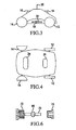
- Figure 1 is a perspective view of the cleaning unit of the present invention.
- Figure 2 is a bottom cut away view of the unit showing the front wheels and axle.
- Figure 3 is a side view of the cleaning unit of the present invention.
- Figure 4 is a bottom view of the cleaning unit of the present invention.
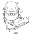
- Figure 5 is a perspective view of the motor and pump assembly of the present invention.
- Figure 6 is a view of the strain relief arrangement used in the present invention.
- Figure 7 is a circuit diagram of the electrical portion of the present invention.
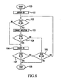
- Figure 8 is a flow chart showing the operation of the present invention.
- the device includes a body which is generally rectangular, having a domed top.
- the device includes a pair of front wheels 14 and a pair of rear wheels 12. Each pair of wheels is connected to an axle and fixedly connected thereto.
- Handles 18 are provided on the sides of the device for convenient lifting. Handles are made hollow, to provide buoyancy.
- Nozzles 16 are directed in opposite directions toward the front and back. These nozzles are utilized for propulsion as will be described later.
- a power cord 20 enters the device from the top in a watertight connection.
- the power cord is connected to a motor and pump arrangement (not shown) which is arranged inside the device.
- a motor and pump arrangement (not shown) which is arranged inside the device.
- water is first sucked up through the bottom of the device through doors 34 (see Figure 4 ).
- a reusable filter bag is arranged inside the housing so that water entering through the doors passes through the filter bag before entering the pump.
- the filter bag is arranged between the doors 34 and the pump.
- the pump ejects water and directs it to one of the two nozzles where it forms a water jet. This jetting action causes the device to move in the opposite direction to the jet.
- the cleaning device change direction at least slightly when it impacts a wall of the pool so that it does not track the same path over and over.
- this is accomplished by having at least one of the axles swivel about a pivot.
- wheels 14 are fixedly connected to axle 22.
- This axle is mounted on pivot 24 which allows the axle to move forward and backward.
- the amount of forward and backward movement is limited by a rotating fork 26 having two projections 28, with one on either side of the axle.
- the axle pivots it is limited in the amount of pivoting by the projections.
- the projections are spaced from each other by an amount to allow sufficient pivoting so that different paths of motion can occur.
- the rotating fork is adjustable by turning it along its axis. This gives a selection of positions and hence a selection of movements of the cleaning device.
- Ratchet device 30 is mounted on the rotating fork so as to provide a plurality of distinct positions of the fork. For example, three positions may be possible, a first where the projections are centered along the line perpendicular to the direction of movement, a second where the projections are centered forward to this line, and a third, where the projections are centered behind this line.
- the axle may pivot in a range from slightly clockwise of the center of position to slightly counterclockwise. In the other two positions, the axle will swing by the same amount, but centered on a different position.
- the pattern that the cleaner follows may be varied since different patterns may be more effective for different size and shape pools. Since the power cable is connected to the transformer, which is stationary while the cleaner moves around in the pool. When the cleaner reverse to the left, it will twist the power cable clockwise. When the cleaner is reverse to the right, it will twist the power cable anticlockwise.
- the device not only allows convenient cleaning pattern adjustment, but also simple and easy unwinding the power cable automatically while the cleaner is cleaning the pool.
- the pivot point 24 is centered. This may be placed off center if desired.
- wheels 14 are shown as having a cup or dome shape on the inside part of the wheel, rather than having a solid disc. This shape allows the wheel to turn more freely so that the inner edge does not rub against the side of the body when the axle pivots While this shape is preferable, other shapes, including traditional disc shapes could be used.
- the wheels are fixed solidly to the axle so that both wheels must turn together.
- the rear wheels 12 may be traditional disc shaped wheels with a fixed axle or may also pivot in the same manner.
- the provision of the front wheel being cup-shaped has an additional benefit in that this provides a narrow surface in contact with the ground which makes the steering more sensitive. This helps to enhance the pivoting action of the axle.
- the wheel may also have a spacer or other mechanism to prevent it from touching the body and to prevent any movement of the wheel along the axle. Thus, the wheel is fixed to the axle both in its rotation and along its axis.
- the rotating fork it is also possible to use a different mechanism then the rotating fork to control the position of the swivel.
- another mechanism could be a sleeve having an oval shape in cross section which fits over the axle and allows the axle to move back and forth within the sleeve.
- the sleeve would be fixed for a given position but could occupy three or more positions just as the rotating fork.
- the concept of the pivoting axle is very simple. When the unit is being moved forwardly, the axle will assume a certain position. However, it has been found that when the unit reverses direction, the axle will also pivot, if allowed to do so. This pivoting action of the axle causes the device to follow a different path when the device is reversed. This has been found to be true even if the surface on which the wheels are placed is uniform and level. Since the axle pivots when the direction is reversed, the unit will take a different path every time the direction is reversed, and as a result, a completely random pattern will be generated so that the entire pool bottom will be covered by this random movement. This arrangement allows the entire pool to be cleaned without intervention by the operator and without any complicated mechanical parts. It also does not require the use of additional power to change the direction of the device.
- Doors 34 are hinged so as to move inwardly and allow water to easily move up into the inside of the body of the unit.
- the trapped water inside the body will not flow back through this door and in fact will act as a check valve because the weight of the water will force the door back into its seat to prevent water from escaping.
- This is actually desirable because the water at this location is on the inside of the filter and any water escaping from this direction would carry the dirt and debris back out into the pool. It is instead desirable to have a different egress for the trapped water.
- Doors 32 are provided on the sides or other location of the body outside the filter. In a preferred arrangement, the doors are actually placed directly under the handles 18 so that the hinge arrangement of the doors can be mounted on the structure that holds the handle.
- the doors 32 could be placed at any location of the body as long as it is arranged on the downstream side of the filter. More than one such door can be provided and preferably one is placed on opposite sides of the unit near each handle. While these doors have previously been made of soft material, they tend to deform with age. In the present device, these doors are made of relatively hard material and are hinged to swing outwardly. The doors are spring loaded so as to help keep them closed and in firm contact with the seat. This prevents the door from warping, and thus prevents deterioration with age.
- the weight of the water inside the unit will force the doors 32 open against the action of the spring. This does not occur when the unit is below the water surface because the weight of the water inside the unit is balanced by the water pressure from outside.
- the pump When the pump is turned on, the water chamber will create a partial vacuum, that sucks and close the two side doors. However, as soon as the unit is lifted above the surface, the water inside will force the doors open against the action of the spring and the water will escape.
- Figure 5 shows the motor and pump assembly 50 which Is mounted inside the body of the cleaning unit.
- the assembly is actually shown in the inverted position and would normally be placed upside down so that horns 62 align with nozzle 16. Thus the bottom part of the assembly 52 would actually face the bottom of the unit.
- This assembly is mounted using bolts or similar fasteners so that it hangs down from the top of the body inside the unit.
- the assembly 50 includes a motor, control PCB and pump (not seen).
- the housing which contains the motor and pump includes three parts, a bottom plastic piece 52, a top plastic piece 54, and a central metal piece 56.
- Within the assembly there is a wall dividing the motor from the pump with the three exterior parts and this wall forming a hermetically sealed unit which contains the motor.
- This compartment contains the motor and is also filled with a non-conductive oil for transferring heat from the motor to the housing.
- the metal central portion of the housing is designed to remove the heat from the oil and transfer it to the outside. Since the unit is normally filled with water when operating, the water from the swimming pool carries the heat away from the metal portion.
- the movement of the shaft of the motor spinning inside the chamber helps to circulate the dielectric liquid throughout the chamber and therefore helps the heat transfer through the metal section.
- the liquid contained in the chamber helps to prevent water leaks by providing a better pressure balance than if it was filled with air.
- the motor includes a shaft which extends through the dividing wall and is connected to an impeller of the pump.
- the pump part of the assembly is not hermetically sealed since it must be in contact with the pool water to operate.
- the pool water may enter the impeller from the central portion of the top of the assembly. It is desirable to place the pump inlet as close to the top of the unit as possible, to minimize air trapped inside the unit. If any air left and trapped, it can easily be displaced. This location is preferable since it is farthest from the doors 34 where the water enters the unit and accordingly is less likely to ingest debris. Also, this point is centrally located causing the suction to be as uniform as possible.
- the entrance to the pump could be at any point in the top portions of the housing and could even be in more than one location.
- the exit for the pump is below the diverter valve assembly 60.
- This exit port is connected to horns 62 by a diverter valve assembly 60.
- This assembly includes a solenoid which drives the valve to one of two locations so that only one of the two horns is connected to the pump exit port at a time.
- the circuit board for controlling the operation of the motor and solenoid is preferably contained within the chamber for the motor to prevent any possible contact with the pool water. It would also be possible for the solenoid to actually be contained within the same chamber and be connected to the diverter valve through a mechanical connection which is sealed.
- the motor is connected to a source of electrical power and to a controller on the circuit board.
- the motor Upon a command from the circuit board controller, the motor is turned on, driving the impeller of the pump and causing water to be sucked into the pump and driven out through one of the two horns.
- the particular direction is chosen by the controller and determined by the position of the diverter valve.
- a signal is sent to the solenoid to change the position of the diverter valve so that the expelled water is driven out the opposite horn and nozzle to reverse the direction of the device.
- the solenoid used for the diverter valve can be a single solenoid with a spring loaded return, a double solenoid, a servomotor, or any other electro-mechanical device which could assume two different positions.
- Figure 6 shows an arrangement to provide a water proof connection through wires entering the motor chamber.
- a strain relief device 66 is mounted on wire 70.
- This strain relief device is made of elastic material and preferably the same type of material as the exterior of the wire so that it bonds easily.
- the diverter device has a shape which corresponds to the seat provided on the wall of the chamber 72. Threads are provided on the internal part of this seat arrangement and the strain relief device is placed therein in solid contact with the seat.
- a nut 74 having exterior threads is placed within the same device and forms a seat on the other side of the strain relief device. The thread is tightened into the body arrangement so that the strain relief device is firmly seated against both sides, thus forming a water proof connection and also a strain relief device at the same time.
- the present invention determines this in a simple fashion by placing a well known reed switch arrangement within one or more wheels of the device, preferably one of the rear wheels 12.
- the reed switch is mounted on a fixed portion of the housing or wheel assembly and one or more magnetic devices are placed on the moving part of the wheel in close proximity to the reed switch so that as the wheel turns, each magnet causes the reed switch to close as it passes thereby.
- the reed switch will close a circuit once for each wheel rotation for each magnet.
- two magnets are provided on the wheel two circuit closings will occur for each rotation.
- either one of the wheel stops sending signal out indicates the unit is either hitting the wall at an angle, or the unit gets hang up on one side. It may also be possible to utilize the different signals to provide other indicators.
- FIG. 7 is a circuit diagram showing electrical connections of the unit.
- Incoming house current is received by transformer 80 which steps down the voltage to 24 volts. It may also contain an on/off switch, circuit breaker, and other safety devices. Typically, this unit will be self-contained and sit on the outside of the pool so that only 24 volt power is applied to the water.
- the output of this transformer is connected by a long wire, indicated by the dotted lines to the cleaning unit.
- the wire may be made with a buoyant outer material so that the wire floats on the water, and does not pull against the unit nor lie on the floor of the pool and thus get in the way of the unit.
- the motor 82 is connected to this 24 volt power and is turned on and off by a switch 84.
- a mechanical switch is shown, in reality, an electronic switch is preferable and if desired, could be a switch which could even control the speed of the motor.
- This switch is controlled by controller 86 which controls all of the operation of the device.
- the controller receives inputs from an oscillator 88 and reed switch 90.
- the reed switch is connected to at least one of the wheels to indicate whether the device is moving or not.
- the oscillator provides a clock signal which is provided to various registers in the controller to determine periods of time.
- a unit 91 converts the 24 volt AC signal to a DC signal using diodes or other devices to provide a DC source of power for those parts which require DC current.
- This power is provided to unit 92 which steps down the voltage of the DC current to the standard voltage applied to the circuit board such as three volts. This provides the power to the chips and other components of the circuit board.
- Relay 94 also receives the DC current and is turned on and off by switch 95 under the control of the controller 86. This switch likewise can be an electronic switch rather than a mechanical switch. When the controller closes the switch, relay 94 fires and switches the power on in solenoid 96. This solenoid is used to control the diverter valve, as described above.
- the controller closes switch 84 and causes the motor to operate which pumps water out nozzle 16, causing the unit to move across the floor of the pool. As the unit moves, all four wheels also move, causing reed switch 90 to periodically open and close giving an indication to the controller that the device is moving.
- the controller closes switch 95 which causes relay 94 to activate solenoid 96. This causes the diverter valve to change positions and send high powered water from the pump through the other nozzle causing the unit to move in the opposite direction.
- the axle Due to the pivoting action of the front axle, when the unit changes direction, the axle will pivot slightly so that the path it takes in going in the opposite direction will be slightly different from that in the forward direction. As a result, the cleaning device continually changes paths as it moves around the pool. Given enough time, the random path will cover essentially all of the bottom of the pool so that the entire pool bottom will be cleaned in the process. Empiricly, three hours is sufficient time to clean most pools and the individual owner can determine by observation if a lesser amount of time is desirable.
- the controller includes at least three timers to help control the operation of the device.
- a first timer is merely set for the time of operation of the entire device. Thus, this timer will indicate when three hours has passed so that the controller will know that it is possible to shut down the operation of the device at that time.
- timers may be involved to determine any problems in the cleaning unit. For example, if the cleaning unit will normally traverse the pool in thirty seconds, and hence change direction at that time, a timer may be set for a larger amount of time, such as sixty seconds, and determine if the wheels have stopped during that time period. If the wheels have not stopped in sixty seconds, this may indicate a situation where the unit has gotten hung up on an object, such as a drain in the bottom of the pool. If the particular shape of the drain or other obstacle catches a wheel, it is possible that the unit will continue to move in a tight circle so that the wheels continue to move while the cleaning device is basically trapped. Without this timer, the controller would not realize that anything was wrong.
- Another timer of much shorter duration such as three seconds can also be implemented to determine if the wheel stops very quickly after turning on. This would be the situation where the unit gets trapped against a ladder or in a corner and continually reverses direction, but follows a very short closed path. This helps the controller to determine that this situation exists.
- FIG 8 is a flow chart indicating the operation of the unit, especially in regard to the various timers.
- step 100 the operation begins, the registers are initialized and the controller is set up and power starts to flow.
- step 101 the motor is turned on and the unit starts the cleaning operation.
- step 102 if the controller senses that the wheels have stopped moving within sixty seconds, normal operation is determined and if the answer is yes, the direction of the movement is changed using solenoid 96 and the diverter valve as indicated in step 103.
- the three second timer determines in step 104 whether wheels have stopped moving within three seconds of the change. If it has not, this indicates normal operation and the device continues to operate normally unless the three hour limit has been reached as indicated in step 105. If the limit is not reached, normal operation returns to step 102. If the limit has been reached, the device will stop as indicated in step 108.
- step 104 If the result of step 104 indicates that the device stopped within three seconds of changing direction, the motor is paused as indicated in step 106 and direction changed again. If the wheel stops again in three seconds as indicated in step 107, the device is stopped. If it has not stopped within three seconds after the pause, it is assumed that normal operation has resumed and the total three hour time limit is considered.
- step 102 If the answer to step 102 is that the device did not stop within sixty seconds, this indicates that the cleaning unit may have become hung up and the motor is paused and reversed in the same manner in step 106 and 107 to determine if it can be recovered. If not, the unit is stopped.
- the controller can determine if the device is moving normally and changing direction every sixty seconds or less, and determine if the unit is trapped and reversing every three seconds or less.
- the controller can also include other problem determining features if desired.
- the controller can activate some visual or auditory signal to indicate to the owner that proper operation has ceased due to a problem.
Landscapes
- Engineering & Computer Science (AREA)
- Architecture (AREA)
- Civil Engineering (AREA)
- Structural Engineering (AREA)
- Cleaning By Liquid Or Steam (AREA)
- Devices For Medical Bathing And Washing (AREA)
Claims (9)
- Schwimmbad-Reinigungsgerät (10) aufweisend:einen hohlen Körper, der auf Rädern (12, 14) montiert ist;eine Pumpe, um Wasser aus dem Schwimmbad in den hohlen Körper und erneut nach außen zu bewegen;einen Filter, um Schmutz aus in den Körper gepumptem Wasser zu entfernen;nach innen schwenkende Türen (34), die auf der Unterseite des Körpers montiert sind, um ein Eintreten von Wasser zu ermöglichen,dadurch gekennzeichnet, dassdas Schwimmbad-Reinigungsgerät (10) weiter aufweist nach außen schwenkende federbelastete Türen (32), die aus einem starren Material aufgebaut sind und an dem hohlen Körper montiert sind, um Wasser, das gefiltert wurde, ein Austreten zu ermöglichen, wenn das Schwimmbad-Reinigungsgerät aus dem Schwimmbad entnommen wurde, und zwar dadurch, dass das Gewicht des Wassers gegen die nach außen schwenkenden federbelasteten Türen (32) wirkt, um die nach außen schwenkenden federbelasteten Türen (32) zu öffnen, wenn das Schwimmbad-Reinigungsgerät (10) aus dem Schwimmbad entnommen wird.
- Schwimmbad-Reinigungsgerät (10) nach Anspruch 1, wobei die nach außen schwenkenden federbelasteten Türen (32) an Seiten des hohlen Körpers montiert sind.
- Schwimmbad-Reinigungsgerät (10) nach Anspruch 1, wobei die nach innen schwenkenden Türen (34) federbelastet sind.
- Schwimmbad-Reinigungsgerät (10) nach Anspruch 1, wobei die nach innen schwenkenden Türen (34) ermöglichen, dass ein Saugen von der Pumpe ermöglicht, die nach innen schwenkenden Türen (34) während einer Benutzung innerhalb des Schwimmbades zu öffnen, um ein Strömen von Wasser durch das Filter zum Herausfiltern von Schmutz aus diesem zu ermöglichen.
- Schwimmbad-Reinigungsgerät (10) nach Anspruch 3, wobei die federbelasteten, nach innen schwenkenden Türen (34) Rückschlagventile sind, um zu verhindern, dass innerhalb des hohlen Körpers enthaltenes Wasser aus den nach innen schwenkenden Türen (34) austritt, wenn das Schwimmbad-Reinigungsgerät (10) aus dem Schwimmbad entnommen wird.
- Schwimmbad-Reinigungsgerät (10) nach Anspruch 1, wobei es weiter Griffe (18) beinhaltet, die an Seitenabschnitten des hohlen Körpers montiert sind, um das Schwimmbad-Reinigungsgerät (10) zu greifen.
- Schwimmbad-Reinigungsgerät (10) nach Anspruch 6, wobei die nach außen schwenkenden Türen (32) an entgegengesetzten Seiten des Schwimmbad-Reinigungsgerätes (10) in der Nähe jedes Griffes (18) angeordnet sind.
- Schwimmbad-Reinigungsgerät (10) nach Anspruch 1, wobei, wenn das Schwimmbad-Reinigungsgerät (10) im Schwimmbad angeordnet ist, das Gewicht des Wassers außerhalb des Schwimmbad-Reinigungsgerätes (10) und die Federkraft die nach außen schwenkenden federbelasteten Türen (32) in geschlossener Position halten.
- Schwimmbad-Reinigungsgerät (10) nach Anspruch 8, wobei, wenn das Schwimmbad-Reinigungsgerät (10) aus dem Schwimmbad entnommen wird, das Gewicht des Wassers im Inneren der Schwimmbad-Reinigungsgerät (10) die Türen (32) entgegen der Wirkung der Feder aufdrückt.
Applications Claiming Priority (3)
| Application Number | Priority Date | Filing Date | Title |
|---|---|---|---|
| US34923102P | 2002-01-18 | 2002-01-18 | |
| US349231P | 2002-01-18 | ||
| PCT/US2003/001259 WO2003062563A1 (en) | 2002-01-18 | 2003-01-16 | Swimming pool cleaner |
Publications (3)
| Publication Number | Publication Date |
|---|---|
| EP1472425A1 EP1472425A1 (de) | 2004-11-03 |
| EP1472425A4 EP1472425A4 (de) | 2006-05-17 |
| EP1472425B1 true EP1472425B1 (de) | 2011-06-08 |
Family
ID=27613261
Family Applications (1)
| Application Number | Title | Priority Date | Filing Date |
|---|---|---|---|
| EP03731932A Expired - Lifetime EP1472425B1 (de) | 2002-01-18 | 2003-01-16 | Schwimmbadreinigungsgerät |
Country Status (6)
| Country | Link |
|---|---|
| US (3) | US7213287B2 (de) |
| EP (1) | EP1472425B1 (de) |
| AT (1) | ATE512268T1 (de) |
| CA (1) | CA2473684C (de) |
| ES (1) | ES2365729T3 (de) |
| WO (1) | WO2003062563A1 (de) |
Cited By (2)
| Publication number | Priority date | Publication date | Assignee | Title |
|---|---|---|---|---|
| US9945140B2 (en) | 2014-05-30 | 2018-04-17 | Ingenieria Y Marketing, S.A. | Floor and wall cleaner |
| US10249395B2 (en) | 2013-09-20 | 2019-04-02 | Ingenieria Y Marketing, S.A. | Cleaning device for bottom surfaces |
Families Citing this family (46)
| Publication number | Priority date | Publication date | Assignee | Title |
|---|---|---|---|---|
| US20070067930A1 (en) * | 2003-10-14 | 2007-03-29 | Efraim Garti | Cordless pool cleaning robot |
| US8241430B2 (en) * | 2003-11-04 | 2012-08-14 | Aqua Products, Inc. | Directional control method for dual brush robotic pool cleaners |
| US7797780B2 (en) * | 2004-11-12 | 2010-09-21 | Smartpool, Inc. | Wheel arrangement for swimming pool cleaner |
| US7690066B2 (en) * | 2005-11-03 | 2010-04-06 | Zodiac Pool Care, Inc. | Automatic pool cleaner |
| US20080099409A1 (en) * | 2006-10-26 | 2008-05-01 | Aquatron Robotic Systems Ltd. | Swimming pool robot |
| FR2925552B1 (fr) * | 2007-12-21 | 2010-01-22 | Zodiac Pool Care Europe | Appareil roulant nettoyeur de surface immergee a entrainement partiellement hydraulique |
| US7867389B2 (en) * | 2008-05-06 | 2011-01-11 | Pool Technology | Pool cleaning vehicle having an advanced drain system |
| USD598168S1 (en) | 2008-09-16 | 2009-08-11 | Hayward Industries, Inc. | Pool cleaner |
| US8343339B2 (en) | 2008-09-16 | 2013-01-01 | Hayward Industries, Inc. | Apparatus for facilitating maintenance of a pool cleaning device |
| US8110098B2 (en) | 2008-11-18 | 2012-02-07 | Pool Bag Limited | Pool cleaning vehicle with filter element and self locking clip |
| USD630809S1 (en) | 2009-07-01 | 2011-01-11 | Hayward Industries, Inc. | Pool cleaner |
| USD630808S1 (en) | 2009-07-01 | 2011-01-11 | Hayward Industries, Inc. | Pool cleaner |
| US9593502B2 (en) | 2009-10-19 | 2017-03-14 | Hayward Industries, Inc. | Swimming pool cleaner |
| FR2954377B1 (fr) | 2009-12-18 | 2015-03-13 | Zodiac Pool Care Europe | Appareil nettoyeur de surface immergee a moteur electrique unique reversible d'entrainement et de pompage |
| FR2954380B1 (fr) * | 2009-12-18 | 2015-03-20 | Zodiac Pool Care Europe | Appareil nettoyeur de surface immergee a giration par cabrage |
| FR2954379B1 (fr) * | 2009-12-18 | 2012-04-13 | Zodiac Pool Care Europe | Appareil nettoyeur de surface immergee a giration par au moins un organe roulant non moteur decale lateralement |
| CA136282S (en) * | 2010-07-09 | 2011-02-07 | Cristiaan Van Den Heuvel | Compact floating vacuum cleaner |
| US8784652B2 (en) | 2010-09-24 | 2014-07-22 | Poolvergnuegen | Swimming pool cleaner with a rigid debris canister |
| US8869337B2 (en) | 2010-11-02 | 2014-10-28 | Hayward Industries, Inc. | Pool cleaning device with adjustable buoyant element |
| US8956533B2 (en) | 2011-10-03 | 2015-02-17 | Pentair Water Pool And Spa, Inc. | Pool cleaner with multi-stage venturi vacuum assembly |
| US8990990B2 (en) | 2011-10-03 | 2015-03-31 | Pentair Water Pool And Spa, Inc. | Pool cleaner with hydraulic timer assembly |
| US9119463B2 (en) | 2011-10-03 | 2015-09-01 | Pentair Water Pool & Spa, Inc. | Pool cleaner with detachable scrubber assembly |
| US8752226B2 (en) * | 2011-11-28 | 2014-06-17 | Aqua Products, Inc. | Axle controller for automated swimming pool cleaners |
| US9074385B2 (en) | 2012-11-20 | 2015-07-07 | Aqua Products, Inc | Pool cleaning vehicle with mechanism for skewing an axle |
| EP2971411A4 (de) | 2013-03-13 | 2017-04-19 | Pentair Water Pool and Spa, Inc. | Doppelpaddelmechanismus für schwimmbeckenreiniger |
| EP2967268A1 (de) | 2013-03-14 | 2016-01-20 | Hayward Industries, Inc. | Schwimmbeckenreiniger mit beweglichen reinigungselementen |
| US9677294B2 (en) | 2013-03-15 | 2017-06-13 | Hayward Industries, Inc. | Pool cleaning device with wheel drive assemblies |
| USD789003S1 (en) | 2014-11-07 | 2017-06-06 | Hayward Industries, Inc. | Pool cleaner |
| USD787760S1 (en) | 2014-11-07 | 2017-05-23 | Hayward Industries, Inc. | Pool cleaner |
| USD789624S1 (en) | 2014-11-07 | 2017-06-13 | Hayward Industries, Inc. | Pool cleaner |
| USD787761S1 (en) | 2014-11-07 | 2017-05-23 | Hayward Industries, Inc. | Pool cleaner |
| US9856669B2 (en) | 2014-11-24 | 2018-01-02 | Compurobot Technology Company | Advanced pool cleaner construction |
| US9366049B1 (en) | 2014-11-24 | 2016-06-14 | Zhibao Pools Company | Jet propelled pool cleaner |
| WO2016153794A1 (en) | 2015-03-23 | 2016-09-29 | Aqua Products, Inc. | Self-propelled robotic swimming pool cleaner with power-wash assembly for lifting debris from a surface beneath the pool cleaner |
| US10174516B2 (en) * | 2015-07-27 | 2019-01-08 | Matthew P. D'Aguanno | Multi-functional submersible vacuum |
| US9809990B1 (en) * | 2016-09-23 | 2017-11-07 | Compurobot Technology Company | Swimming pool cleaning vehicle with side intake flaps and method therefor |
| US10844621B2 (en) | 2016-12-08 | 2020-11-24 | Zodiac Pool Systems Llc | Enhanced filter door |
| US10214933B2 (en) | 2017-05-11 | 2019-02-26 | Hayward Industries, Inc. | Pool cleaner power supply |
| US10294686B1 (en) | 2018-04-24 | 2019-05-21 | Water Tech, LLC | Rechargeable robotic pool cleaning apparatus |
| USD943849S1 (en) | 2020-01-27 | 2022-02-15 | Matthew P. D'Aguanno | Liquid-submersible vacuum cleaner |
| USD1071427S1 (en) | 2022-04-22 | 2025-04-15 | Matthew P. D'Aguanno | Pool vacuum head |
| US12146340B2 (en) | 2022-08-11 | 2024-11-19 | John Michael Green | Methods, systems, apparatuses, and devices for facilitating cleaning of a pool |
| CN115822335A (zh) * | 2022-10-31 | 2023-03-21 | 浙江明峰工贸股份有限公司 | 带有转向的泳池清洗车 |
| USD1064466S1 (en) * | 2023-02-14 | 2025-02-25 | Compurobot Technology Company | Pool cleaner |
| USD1052836S1 (en) | 2023-03-07 | 2024-11-26 | Matthew P. D'Aguanno | Pool vacuum head |
| US12509899B2 (en) * | 2025-06-25 | 2025-12-30 | Taizhou Dibiao Technology Co., Ltd | Swimming pool cleaning device of underwater robot |
Citations (1)
| Publication number | Priority date | Publication date | Assignee | Title |
|---|---|---|---|---|
| US5337434A (en) * | 1993-04-12 | 1994-08-16 | Aqua Products, Inc. | Directional control means for robotic swimming pool cleaners |
Family Cites Families (53)
| Publication number | Priority date | Publication date | Assignee | Title |
|---|---|---|---|---|
| US2146021A (en) * | 1936-05-29 | 1939-02-07 | Marx & Co Louis | Reversing toy vehicle |
| US2423436A (en) * | 1945-03-30 | 1947-07-08 | Byron Jackson Co | Submersible motorpump |
| US2444912A (en) * | 1947-07-17 | 1948-07-13 | Jr Albert G Bodine | Method and apparatus for pumping |
| US2683956A (en) * | 1949-05-16 | 1954-07-20 | Robert J Conte | Toy automobile |
| US2936187A (en) * | 1955-11-10 | 1960-05-10 | Robert E Peterson | Fluid leakage proof entrance seal |
| US2941025A (en) * | 1957-11-07 | 1960-06-14 | M & W Electric Mfg Co Inc | Cable connectors for meter sockets having hubs |
| US2972002A (en) * | 1958-01-28 | 1961-02-14 | Ted A Wayman | Fluid-tight joint and cable mounting |
| US2988762A (en) * | 1960-02-08 | 1961-06-20 | Hugh H Babcock | Self-steering submarine suction cleaner |
| GB1092133A (en) * | 1965-03-04 | 1967-11-22 | Exxon Research Engineering Co | Apparatus for manoeuvring on a submerged surface |
| US3487149A (en) * | 1968-01-19 | 1969-12-30 | Anaconda Wire & Cable Co | Method for extruding cable covering with a fibrous interlayer |
| US3755843A (en) * | 1971-06-24 | 1973-09-04 | R Hargrave | Pool vacuum system |
| US3860518A (en) * | 1971-08-27 | 1975-01-14 | Evan R Henricksen | Apparatus and method for cleaning swimming pools |
| US3822754A (en) * | 1972-07-26 | 1974-07-09 | M Henkin | Automatic swimming pool cleaner |
| US3886616A (en) * | 1972-12-06 | 1975-06-03 | Fay A Hayes | Hand propelled swimming pool cleaner |
| US4100641A (en) * | 1976-06-24 | 1978-07-18 | Pansini Andrew L | Swimming pool cleaners |
| ZA767474B (en) * | 1976-12-15 | 1978-08-30 | W Rasch | Pool cleaners |
| JPS543376A (en) | 1977-06-09 | 1979-01-11 | Shin Meiwa Ind Co Ltd | Cleaner for water bottom of pool etc. |
| JPS549457A (en) | 1977-06-21 | 1979-01-24 | Shin Meiwa Ind Co Ltd | Bottom cleaner for pool or the like |
| JPS5415365A (en) | 1977-07-06 | 1979-02-05 | Shin Meiwa Ind Co Ltd | Bottom cleaner for pool or the like |
| JPS5445972A (en) | 1977-09-16 | 1979-04-11 | Shin Meiwa Ind Co Ltd | Cleaner for water bottom of swimming pool or the like |
| JPS5445971A (en) | 1977-09-17 | 1979-04-11 | Shin Meiwa Ind Co Ltd | Cleaner for bottom of swimming pool or the like |
| JPS5450157A (en) | 1977-09-27 | 1979-04-19 | Shin Meiwa Ind Co Ltd | Apparatus for cleaning bottom of water in pool or the like |
| US4141101A (en) * | 1978-01-09 | 1979-02-27 | Gibellina Michael C | Self propelled drivehead for automatic swimming pool cleaner |
| US4169484A (en) * | 1978-05-30 | 1979-10-02 | Josef Bonigut | Automatic pool cleaner apparatus |
| DE3110203C2 (de) | 1981-03-17 | 1987-05-14 | Rolf 6450 Hanau Corvinus | Verfahren und Gerät zum Reinigen eines Schwimmbeckens |
| US4429429A (en) * | 1981-08-12 | 1984-02-07 | Altschul Rod H | Device for cleaning swimming pool sidewall |
| US4463520A (en) * | 1983-03-21 | 1984-08-07 | Buddy L Corporation | Self-returning toy vehicle |
| US4558479A (en) * | 1984-01-26 | 1985-12-17 | Alopex Industries, Inc. | Pool cleaner |
| US4589986A (en) * | 1984-01-26 | 1986-05-20 | Alopex Industries, Inc. | Pool cleaner |
| US4607181A (en) * | 1984-12-06 | 1986-08-19 | Hayward Tyler Inc. | High temperature submersible electric motor |
| US4738636A (en) * | 1987-04-13 | 1988-04-19 | Appleton Electric Co. | Strain relief connectors for flexible cord and cable |
| US5099535A (en) * | 1988-02-18 | 1992-03-31 | Daniel J. D. Chauvier | Cleaner for submerged surfaces |
| EP0356577B1 (de) * | 1988-08-20 | 1991-03-27 | Pooltec Establishment | Saugkopf zum Reinigen untergetauchter Flächen |
| US5055000A (en) * | 1989-08-11 | 1991-10-08 | Wayne/Scott Fetzer Company | Enclosed pump motor and housing thereof |
| EP0658863A3 (de) * | 1990-07-11 | 1995-06-28 | Hitachi, Ltd. | Datenspeicherkarte zur Verwendung in einem digitalen Informationssystem |
| ES2087973T3 (es) * | 1990-09-11 | 1996-08-01 | Fred Int Cv | Maquina hidraulica. |
| US5336064A (en) * | 1993-12-06 | 1994-08-09 | Westinghouse Electric Corporation | Electric motor driven pump |
| US5920035A (en) * | 1997-03-12 | 1999-07-06 | Atp International Ltd. | High pressure seal |
| EP1695770A1 (de) * | 1996-06-26 | 2006-08-30 | Melvyn L. Henkin | Automatisches Schwimmbeckenreinigungssystem mit positivem Druck |
| US5974347A (en) * | 1997-03-14 | 1999-10-26 | Nelson; Russell G. | Automated lawn mower |
| SE508755C2 (sv) * | 1997-03-27 | 1998-11-02 | Roxtec Ab | Ledningsgenomföring |
| US5842243A (en) * | 1997-04-24 | 1998-12-01 | Aqua Products Inc. | Manually propelled pool cleaner |
| US6039886A (en) * | 1997-06-25 | 2000-03-21 | Henkin; Melvyn L. | Water suction powered automatic swimming pool cleaning system |
| US5882512A (en) * | 1997-11-05 | 1999-03-16 | Baracuda International Corporation | Automatic swimming pool cleaners and associated components and systems |
| US6294084B1 (en) * | 1997-12-25 | 2001-09-25 | Melvyn L. Henkin | Electric powered automatic swimming pool cleaning system |
| US6387250B1 (en) | 1997-12-26 | 2002-05-14 | Melvyn L. Henkin | Water suction powered automatic swimming pool cleaning system |
| ATE265595T1 (de) * | 1998-09-23 | 2004-05-15 | 3S Systemtechn Ag | Schwimmbadreinrgungsgerät |
| US6412133B1 (en) * | 1999-01-25 | 2002-07-02 | Aqua Products, Inc. | Water jet reversing propulsion and directional controls for automated swimming pool cleaners |
| US6299699B1 (en) * | 1999-04-01 | 2001-10-09 | Aqua Products Inc. | Pool cleaner directional control method and apparatus |
| US6758226B2 (en) * | 1999-04-01 | 2004-07-06 | Aqua Products Inc. | Motion detection and control for automated pool cleaner |
| US6187181B1 (en) * | 1999-11-01 | 2001-02-13 | Polaris Pool Systems, Inc. | Floating skimmer |
| US6268565B1 (en) * | 1999-12-06 | 2001-07-31 | Avaya Technology Corp. | Cable seal for submerged enclosures |
| US6627074B2 (en) * | 2001-01-30 | 2003-09-30 | Filter Specialists, Inc. | Filter element for swimming pool cleaner |
-
2003
- 2003-01-16 AT AT03731932T patent/ATE512268T1/de not_active IP Right Cessation
- 2003-01-16 ES ES03731932T patent/ES2365729T3/es not_active Expired - Lifetime
- 2003-01-16 EP EP03731932A patent/EP1472425B1/de not_active Expired - Lifetime
- 2003-01-16 CA CA002473684A patent/CA2473684C/en not_active Expired - Fee Related
- 2003-01-16 WO PCT/US2003/001259 patent/WO2003062563A1/en not_active Ceased
- 2003-01-16 US US10/345,152 patent/US7213287B2/en not_active Expired - Fee Related
-
2007
- 2007-04-19 US US11/785,680 patent/US20070192970A1/en not_active Abandoned
- 2007-04-19 US US11/785,684 patent/US20070192971A1/en not_active Abandoned
Patent Citations (1)
| Publication number | Priority date | Publication date | Assignee | Title |
|---|---|---|---|---|
| US5337434A (en) * | 1993-04-12 | 1994-08-16 | Aqua Products, Inc. | Directional control means for robotic swimming pool cleaners |
Cited By (2)
| Publication number | Priority date | Publication date | Assignee | Title |
|---|---|---|---|---|
| US10249395B2 (en) | 2013-09-20 | 2019-04-02 | Ingenieria Y Marketing, S.A. | Cleaning device for bottom surfaces |
| US9945140B2 (en) | 2014-05-30 | 2018-04-17 | Ingenieria Y Marketing, S.A. | Floor and wall cleaner |
Also Published As
| Publication number | Publication date |
|---|---|
| EP1472425A4 (de) | 2006-05-17 |
| US20070192970A1 (en) | 2007-08-23 |
| ATE512268T1 (de) | 2011-06-15 |
| US20030159723A1 (en) | 2003-08-28 |
| ES2365729T3 (es) | 2011-10-10 |
| US20070192971A1 (en) | 2007-08-23 |
| US7213287B2 (en) | 2007-05-08 |
| CA2473684A1 (en) | 2003-07-31 |
| WO2003062563A1 (en) | 2003-07-31 |
| EP1472425A1 (de) | 2004-11-03 |
| CA2473684C (en) | 2009-10-20 |
Similar Documents
| Publication | Publication Date | Title |
|---|---|---|
| EP1472425B1 (de) | Schwimmbadreinigungsgerät | |
| CA2906133C (en) | Automatic electric top bottom swimming pool cleaner with internal pumps | |
| US10214932B2 (en) | Robotic pool cleaning apparatus | |
| US10294686B1 (en) | Rechargeable robotic pool cleaning apparatus | |
| AU2002252660B2 (en) | Electric powered automatic swimming pool cleaning system | |
| US7118632B2 (en) | Pool cleaning method and device | |
| US5337434A (en) | Directional control means for robotic swimming pool cleaners | |
| EP1785552B1 (de) | Automatischer Schwimmbeckenreiniger | |
| US6039886A (en) | Water suction powered automatic swimming pool cleaning system | |
| US5788850A (en) | Pool surface sweep system | |
| US7101475B1 (en) | Autonomously navigating solar swimming pool skimmer | |
| AU715666B2 (en) | Water suction powered automatic swimming pool cleaning system | |
| EP0969167A2 (de) | Schwimmbeckenreiniger | |
| JPH0947735A (ja) | 水槽清浄機 | |
| US3676884A (en) | Random motion suction cleaner | |
| AU2002252660A1 (en) | Electric powered automatic swimming pool cleaning system | |
| AU2006244495A1 (en) | Pool cleaner control subsystem | |
| CN100497871C (zh) | 一种水力驱动的水池清洁机 | |
| EP0835357B1 (de) | Automatisches schwimmbadreinigungssystem | |
| CN113914679A (zh) | 游泳池潜浮式自动航行吸污装置 | |
| JPH09215621A (ja) | 浴槽清掃機 |
Legal Events
| Date | Code | Title | Description |
|---|---|---|---|
| PUAI | Public reference made under article 153(3) epc to a published international application that has entered the european phase |
Free format text: ORIGINAL CODE: 0009012 |
|
| 17P | Request for examination filed |
Effective date: 20040719 |
|
| AK | Designated contracting states |
Kind code of ref document: A1 Designated state(s): AT BE BG CH CY CZ DE DK EE ES FI FR GB GR HU IE IT LI LU MC NL PT SE SI SK TR |
|
| AX | Request for extension of the european patent |
Extension state: AL LT LV MK RO |
|
| RIN1 | Information on inventor provided before grant (corrected) |
Inventor name: HUI, JOSEPH |
|
| RIN1 | Information on inventor provided before grant (corrected) |
Inventor name: HUI, JOSEPH W.T. |
|
| A4 | Supplementary search report drawn up and despatched |
Effective date: 20060405 |
|
| 17Q | First examination report despatched |
Effective date: 20081203 |
|
| GRAP | Despatch of communication of intention to grant a patent |
Free format text: ORIGINAL CODE: EPIDOSNIGR1 |
|
| GRAJ | Information related to disapproval of communication of intention to grant by the applicant or resumption of examination proceedings by the epo deleted |
Free format text: ORIGINAL CODE: EPIDOSDIGR1 |
|
| GRAP | Despatch of communication of intention to grant a patent |
Free format text: ORIGINAL CODE: EPIDOSNIGR1 |
|
| GRAS | Grant fee paid |
Free format text: ORIGINAL CODE: EPIDOSNIGR3 |
|
| GRAA | (expected) grant |
Free format text: ORIGINAL CODE: 0009210 |
|
| AK | Designated contracting states |
Kind code of ref document: B1 Designated state(s): AT BE BG CH CY CZ DE DK EE ES FI FR GB GR HU IE IT LI LU MC NL PT SE SI SK TR |
|
| REG | Reference to a national code |
Ref country code: GB Ref legal event code: FG4D |
|
| REG | Reference to a national code |
Ref country code: CH Ref legal event code: EP |
|
| REG | Reference to a national code |
Ref country code: IE Ref legal event code: FG4D |
|
| REG | Reference to a national code |
Ref country code: DE Ref legal event code: R096 Ref document number: 60337322 Country of ref document: DE Effective date: 20110721 |
|
| REG | Reference to a national code |
Ref country code: NL Ref legal event code: VDEP Effective date: 20110608 |
|
| REG | Reference to a national code |
Ref country code: ES Ref legal event code: FG2A Ref document number: 2365729 Country of ref document: ES Kind code of ref document: T3 Effective date: 20111010 |
|
| PG25 | Lapsed in a contracting state [announced via postgrant information from national office to epo] |
Ref country code: SE Free format text: LAPSE BECAUSE OF FAILURE TO SUBMIT A TRANSLATION OF THE DESCRIPTION OR TO PAY THE FEE WITHIN THE PRESCRIBED TIME-LIMIT Effective date: 20110608 |
|
| PG25 | Lapsed in a contracting state [announced via postgrant information from national office to epo] |
Ref country code: FI Free format text: LAPSE BECAUSE OF FAILURE TO SUBMIT A TRANSLATION OF THE DESCRIPTION OR TO PAY THE FEE WITHIN THE PRESCRIBED TIME-LIMIT Effective date: 20110608 Ref country code: CY Free format text: LAPSE BECAUSE OF FAILURE TO SUBMIT A TRANSLATION OF THE DESCRIPTION OR TO PAY THE FEE WITHIN THE PRESCRIBED TIME-LIMIT Effective date: 20110608 Ref country code: AT Free format text: LAPSE BECAUSE OF FAILURE TO SUBMIT A TRANSLATION OF THE DESCRIPTION OR TO PAY THE FEE WITHIN THE PRESCRIBED TIME-LIMIT Effective date: 20110608 Ref country code: GR Free format text: LAPSE BECAUSE OF FAILURE TO SUBMIT A TRANSLATION OF THE DESCRIPTION OR TO PAY THE FEE WITHIN THE PRESCRIBED TIME-LIMIT Effective date: 20110909 Ref country code: SI Free format text: LAPSE BECAUSE OF FAILURE TO SUBMIT A TRANSLATION OF THE DESCRIPTION OR TO PAY THE FEE WITHIN THE PRESCRIBED TIME-LIMIT Effective date: 20110608 |
|
| PG25 | Lapsed in a contracting state [announced via postgrant information from national office to epo] |
Ref country code: BE Free format text: LAPSE BECAUSE OF FAILURE TO SUBMIT A TRANSLATION OF THE DESCRIPTION OR TO PAY THE FEE WITHIN THE PRESCRIBED TIME-LIMIT Effective date: 20110608 Ref country code: NL Free format text: LAPSE BECAUSE OF FAILURE TO SUBMIT A TRANSLATION OF THE DESCRIPTION OR TO PAY THE FEE WITHIN THE PRESCRIBED TIME-LIMIT Effective date: 20110608 |
|
| PG25 | Lapsed in a contracting state [announced via postgrant information from national office to epo] |
Ref country code: PT Free format text: LAPSE BECAUSE OF FAILURE TO SUBMIT A TRANSLATION OF THE DESCRIPTION OR TO PAY THE FEE WITHIN THE PRESCRIBED TIME-LIMIT Effective date: 20111010 Ref country code: EE Free format text: LAPSE BECAUSE OF FAILURE TO SUBMIT A TRANSLATION OF THE DESCRIPTION OR TO PAY THE FEE WITHIN THE PRESCRIBED TIME-LIMIT Effective date: 20110608 Ref country code: CZ Free format text: LAPSE BECAUSE OF FAILURE TO SUBMIT A TRANSLATION OF THE DESCRIPTION OR TO PAY THE FEE WITHIN THE PRESCRIBED TIME-LIMIT Effective date: 20110608 |
|
| PG25 | Lapsed in a contracting state [announced via postgrant information from national office to epo] |
Ref country code: SK Free format text: LAPSE BECAUSE OF FAILURE TO SUBMIT A TRANSLATION OF THE DESCRIPTION OR TO PAY THE FEE WITHIN THE PRESCRIBED TIME-LIMIT Effective date: 20110608 |
|
| PLBE | No opposition filed within time limit |
Free format text: ORIGINAL CODE: 0009261 |
|
| STAA | Information on the status of an ep patent application or granted ep patent |
Free format text: STATUS: NO OPPOSITION FILED WITHIN TIME LIMIT |
|
| 26N | No opposition filed |
Effective date: 20120309 |
|
| PG25 | Lapsed in a contracting state [announced via postgrant information from national office to epo] |
Ref country code: DK Free format text: LAPSE BECAUSE OF FAILURE TO SUBMIT A TRANSLATION OF THE DESCRIPTION OR TO PAY THE FEE WITHIN THE PRESCRIBED TIME-LIMIT Effective date: 20110608 |
|
| PGFP | Annual fee paid to national office [announced via postgrant information from national office to epo] |
Ref country code: IT Payment date: 20120118 Year of fee payment: 10 |
|
| REG | Reference to a national code |
Ref country code: DE Ref legal event code: R097 Ref document number: 60337322 Country of ref document: DE Effective date: 20120309 |
|
| PG25 | Lapsed in a contracting state [announced via postgrant information from national office to epo] |
Ref country code: MC Free format text: LAPSE BECAUSE OF NON-PAYMENT OF DUE FEES Effective date: 20120131 |
|
| REG | Reference to a national code |
Ref country code: CH Ref legal event code: PL |
|
| GBPC | Gb: european patent ceased through non-payment of renewal fee |
Effective date: 20120116 |
|
| REG | Reference to a national code |
Ref country code: IE Ref legal event code: MM4A |
|
| PG25 | Lapsed in a contracting state [announced via postgrant information from national office to epo] |
Ref country code: LI Free format text: LAPSE BECAUSE OF NON-PAYMENT OF DUE FEES Effective date: 20120131 Ref country code: GB Free format text: LAPSE BECAUSE OF NON-PAYMENT OF DUE FEES Effective date: 20120116 Ref country code: CH Free format text: LAPSE BECAUSE OF NON-PAYMENT OF DUE FEES Effective date: 20120131 |
|
| PG25 | Lapsed in a contracting state [announced via postgrant information from national office to epo] |
Ref country code: IE Free format text: LAPSE BECAUSE OF NON-PAYMENT OF DUE FEES Effective date: 20120116 |
|
| PG25 | Lapsed in a contracting state [announced via postgrant information from national office to epo] |
Ref country code: BG Free format text: LAPSE BECAUSE OF FAILURE TO SUBMIT A TRANSLATION OF THE DESCRIPTION OR TO PAY THE FEE WITHIN THE PRESCRIBED TIME-LIMIT Effective date: 20110908 |
|
| PG25 | Lapsed in a contracting state [announced via postgrant information from national office to epo] |
Ref country code: TR Free format text: LAPSE BECAUSE OF FAILURE TO SUBMIT A TRANSLATION OF THE DESCRIPTION OR TO PAY THE FEE WITHIN THE PRESCRIBED TIME-LIMIT Effective date: 20110608 |
|
| PG25 | Lapsed in a contracting state [announced via postgrant information from national office to epo] |
Ref country code: LU Free format text: LAPSE BECAUSE OF NON-PAYMENT OF DUE FEES Effective date: 20120116 |
|
| PG25 | Lapsed in a contracting state [announced via postgrant information from national office to epo] |
Ref country code: HU Free format text: LAPSE BECAUSE OF FAILURE TO SUBMIT A TRANSLATION OF THE DESCRIPTION OR TO PAY THE FEE WITHIN THE PRESCRIBED TIME-LIMIT Effective date: 20030116 |
|
| REG | Reference to a national code |
Ref country code: FR Ref legal event code: PLFP Year of fee payment: 14 |
|
| PG25 | Lapsed in a contracting state [announced via postgrant information from national office to epo] |
Ref country code: IT Free format text: LAPSE BECAUSE OF NON-PAYMENT OF DUE FEES Effective date: 20140116 |
|
| REG | Reference to a national code |
Ref country code: FR Ref legal event code: PLFP Year of fee payment: 15 |
|
| REG | Reference to a national code |
Ref country code: FR Ref legal event code: PLFP Year of fee payment: 16 |
|
| PGFP | Annual fee paid to national office [announced via postgrant information from national office to epo] |
Ref country code: FR Payment date: 20171211 Year of fee payment: 16 |
|
| PGFP | Annual fee paid to national office [announced via postgrant information from national office to epo] |
Ref country code: DE Payment date: 20180103 Year of fee payment: 16 Ref country code: ES Payment date: 20180201 Year of fee payment: 16 |
|
| REG | Reference to a national code |
Ref country code: DE Ref legal event code: R119 Ref document number: 60337322 Country of ref document: DE |
|
| PG25 | Lapsed in a contracting state [announced via postgrant information from national office to epo] |
Ref country code: DE Free format text: LAPSE BECAUSE OF NON-PAYMENT OF DUE FEES Effective date: 20190801 Ref country code: FR Free format text: LAPSE BECAUSE OF NON-PAYMENT OF DUE FEES Effective date: 20190131 |
|
| REG | Reference to a national code |
Ref country code: ES Ref legal event code: FD2A Effective date: 20200310 |
|
| PG25 | Lapsed in a contracting state [announced via postgrant information from national office to epo] |
Ref country code: ES Free format text: LAPSE BECAUSE OF NON-PAYMENT OF DUE FEES Effective date: 20190117 |