EP1471769A2 - Surface-mountable electronic component - Google Patents
Surface-mountable electronic component Download PDFInfo
- Publication number
- EP1471769A2 EP1471769A2 EP04250778A EP04250778A EP1471769A2 EP 1471769 A2 EP1471769 A2 EP 1471769A2 EP 04250778 A EP04250778 A EP 04250778A EP 04250778 A EP04250778 A EP 04250778A EP 1471769 A2 EP1471769 A2 EP 1471769A2
- Authority
- EP
- European Patent Office
- Prior art keywords
- case
- cover
- reflow
- package according
- temperature
- Prior art date
- Legal status (The legal status is an assumption and is not a legal conclusion. Google has not performed a legal analysis and makes no representation as to the accuracy of the status listed.)
- Granted
Links
Images


Classifications
-
- H—ELECTRICITY
- H04—ELECTRIC COMMUNICATION TECHNIQUE
- H04R—LOUDSPEAKERS, MICROPHONES, GRAMOPHONE PICK-UPS OR LIKE ACOUSTIC ELECTROMECHANICAL TRANSDUCERS; ELECTRIC HEARING AIDS; PUBLIC ADDRESS SYSTEMS
- H04R17/00—Piezoelectric transducers; Electrostrictive transducers
-
- A—HUMAN NECESSITIES
- A45—HAND OR TRAVELLING ARTICLES
- A45B—WALKING STICKS; UMBRELLAS; LADIES' OR LIKE FANS
- A45B3/00—Sticks combined with other objects
- A45B3/02—Sticks combined with other objects with illuminating devices
- A45B3/04—Sticks combined with other objects with illuminating devices electrical
-
- F—MECHANICAL ENGINEERING; LIGHTING; HEATING; WEAPONS; BLASTING
- F21—LIGHTING
- F21V—FUNCTIONAL FEATURES OR DETAILS OF LIGHTING DEVICES OR SYSTEMS THEREOF; STRUCTURAL COMBINATIONS OF LIGHTING DEVICES WITH OTHER ARTICLES, NOT OTHERWISE PROVIDED FOR
- F21V23/00—Arrangement of electric circuit elements in or on lighting devices
- F21V23/04—Arrangement of electric circuit elements in or on lighting devices the elements being switches
-
- F—MECHANICAL ENGINEERING; LIGHTING; HEATING; WEAPONS; BLASTING
- F21—LIGHTING
- F21V—FUNCTIONAL FEATURES OR DETAILS OF LIGHTING DEVICES OR SYSTEMS THEREOF; STRUCTURAL COMBINATIONS OF LIGHTING DEVICES WITH OTHER ARTICLES, NOT OTHERWISE PROVIDED FOR
- F21V33/00—Structural combinations of lighting devices with other articles, not otherwise provided for
- F21V33/0004—Personal or domestic articles
-
- H—ELECTRICITY
- H05—ELECTRIC TECHNIQUES NOT OTHERWISE PROVIDED FOR
- H05K—PRINTED CIRCUITS; CASINGS OR CONSTRUCTIONAL DETAILS OF ELECTRIC APPARATUS; MANUFACTURE OF ASSEMBLAGES OF ELECTRICAL COMPONENTS
- H05K3/00—Apparatus or processes for manufacturing printed circuits
- H05K3/30—Assembling printed circuits with electric components, e.g. with resistors
- H05K3/32—Assembling printed circuits with electric components, e.g. with resistors electrically connecting electric components or wires to printed circuits
- H05K3/34—Assembling printed circuits with electric components, e.g. with resistors electrically connecting electric components or wires to printed circuits by soldering
- H05K3/341—Surface mounted components
- H05K3/3431—Leadless components
- H05K3/3442—Leadless components having edge contacts, e.g. leadless chip capacitors, chip carriers
-
- A—HUMAN NECESSITIES
- A45—HAND OR TRAVELLING ARTICLES
- A45B—WALKING STICKS; UMBRELLAS; LADIES' OR LIKE FANS
- A45B2200/00—Details not otherwise provided for in A45B
- A45B2200/10—Umbrellas; Sunshades
- A45B2200/1009—Umbrellas; Sunshades combined with other objects
- A45B2200/1018—Umbrellas; Sunshades combined with other objects with illuminating devices, e.g. electrical
-
- A—HUMAN NECESSITIES
- A45—HAND OR TRAVELLING ARTICLES
- A45B—WALKING STICKS; UMBRELLAS; LADIES' OR LIKE FANS
- A45B2200/00—Details not otherwise provided for in A45B
- A45B2200/10—Umbrellas; Sunshades
- A45B2200/1081—Umbrella handles
-
- H—ELECTRICITY
- H05—ELECTRIC TECHNIQUES NOT OTHERWISE PROVIDED FOR
- H05K—PRINTED CIRCUITS; CASINGS OR CONSTRUCTIONAL DETAILS OF ELECTRIC APPARATUS; MANUFACTURE OF ASSEMBLAGES OF ELECTRICAL COMPONENTS
- H05K2201/00—Indexing scheme relating to printed circuits covered by H05K1/00
- H05K2201/01—Dielectrics
- H05K2201/0104—Properties and characteristics in general
- H05K2201/0129—Thermoplastic polymer, e.g. auto-adhesive layer; Shaping of thermoplastic polymer
-
- H—ELECTRICITY
- H05—ELECTRIC TECHNIQUES NOT OTHERWISE PROVIDED FOR
- H05K—PRINTED CIRCUITS; CASINGS OR CONSTRUCTIONAL DETAILS OF ELECTRIC APPARATUS; MANUFACTURE OF ASSEMBLAGES OF ELECTRICAL COMPONENTS
- H05K2201/00—Indexing scheme relating to printed circuits covered by H05K1/00
- H05K2201/10—Details of components or other objects attached to or integrated in a printed circuit board
- H05K2201/10613—Details of electrical connections of non-printed components, e.g. special leads
- H05K2201/10621—Components characterised by their electrical contacts
- H05K2201/10727—Leadless chip carrier [LCC], e.g. chip-modules for cards
-
- H—ELECTRICITY
- H05—ELECTRIC TECHNIQUES NOT OTHERWISE PROVIDED FOR
- H05K—PRINTED CIRCUITS; CASINGS OR CONSTRUCTIONAL DETAILS OF ELECTRIC APPARATUS; MANUFACTURE OF ASSEMBLAGES OF ELECTRICAL COMPONENTS
- H05K2203/00—Indexing scheme relating to apparatus or processes for manufacturing printed circuits covered by H05K3/00
- H05K2203/30—Details of processes not otherwise provided for in H05K2203/01 - H05K2203/17
- H05K2203/304—Protecting a component during manufacturing
-
- Y—GENERAL TAGGING OF NEW TECHNOLOGICAL DEVELOPMENTS; GENERAL TAGGING OF CROSS-SECTIONAL TECHNOLOGIES SPANNING OVER SEVERAL SECTIONS OF THE IPC; TECHNICAL SUBJECTS COVERED BY FORMER USPC CROSS-REFERENCE ART COLLECTIONS [XRACs] AND DIGESTS
- Y02—TECHNOLOGIES OR APPLICATIONS FOR MITIGATION OR ADAPTATION AGAINST CLIMATE CHANGE
- Y02P—CLIMATE CHANGE MITIGATION TECHNOLOGIES IN THE PRODUCTION OR PROCESSING OF GOODS
- Y02P70/00—Climate change mitigation technologies in the production process for final industrial or consumer products
- Y02P70/50—Manufacturing or production processes characterised by the final manufactured product
Definitions
- the present invention relates to a package structure of a surface-mountable electronic component.
- Piezoelectric sound components have been widely used as a piezoelectric sounders for generating audible alarm or operational sound, a piezoelectric receiver, or other components in electronic apparatuses, home appliances, cellular phones, and so forth.
- a typical piezoelectric sound component includes a diaphragm fixed in a case closed with a cover, as disclosed in Japanese Unexamined Patent Application Publication No. 2000-310990.
- the piezoelectric sound component is desired to be of a surface-mountable type capable of being directly mounted on a circuit board.
- the case and the cover of the electronic component must have a heat resistance higher than a reflow temperature.
- the case and the cover are formed of a heat-resistant resin, such as LCP (liquid crystal polymer), SPS (syndiotactic polystyrene), PPS (polyphenylene sulfide), or epoxy resin.
- Reflow temperature depends on the constituents of the solder used. Recent restriction of lead-containing solder has been expanding the range of application of lead-free solder. While lead-containing solder is reflowed in the range of 220°C to 240°C, lead-free solder is reflowed at a temperature of 250°C or more and requires high heat resistance of the package of electronic components accordingly.
- the heat resistance or softening temperature of a resin case and cover is set to be higher than a reflow temperature.
- the shapes of the case and cover are therefore maintained without being softened by reflow.
- Reflow using lead-containing solder does not seriously affect the package structure having the case and cover.
- a case and a cover formed of a resin having a softening temperature higher than the reflow temperature are subjected to a reflow process at a high temperature, a stress resulting from the difference in thermal expansion between the case and the cover is placed on their bonded surfaces. The stress is likely to undesirably cause the case and the cover to separate during reflow or in a subsequent drop impact test.
- Thermal expansion of resins, particularly LCP is varied depending on molding conditions, shapes, flow directions, and so forth even in the same material, and difference in thermal expansion among portions is consequently large. Therefore, the foregoing problems become more pronounced.
- the present invention addresses the problem described above.
- a package of a surface-mountable electronic component which may be reflow-soldered to a circuit board at a reflow temperature of about 250°C or more, including a case with an opening, holding an element of the electronic component therein, and a cover bonded to the case so as to close the opening.
- the case has a softening temperature that is higher than the reflow temperature
- the cover has a softening temperature that is lower than the reflow temperature.
- Embodiments of the present invention may provide a package for surface-mountable electronic components that may reduce the stress applied to the bonded surfaces of the case and the cover by high temperature reflow soldering and that may prevent separation of bonded surfaces and a decrease in bonding strength that may occur after reflow.
- Softening temperature here refers to a temperature according to Method B specified in JIS K 7207.
- both the case and the cover have a softening temperature higher than the reflow temperature, undesired distortion remains in the case or the cover after reflow.
- softening the cover preferably prevents the distortion after reflow. Since the softening temperature of the case is higher than the reflow temperature, no excessive load is applied to the element of the electronic component even if the element has a low strength. Thus, the characteristics of the element may be prevented from being deviated from or undesirably changed. Also, the outer dimensions are stabilized.
- the case and the cover may be formed of an LCP.
- LCP is suitable for surface-mountable electronic component packages because of its superior heat resistance and solvent resistance.
- thermal expansion of LCP is varied depending on molding conditions, shapes, flow directions, and so forth even in the same material, and the difference in thermal expansion among portions is consequently large.
- the thermal expansion coefficient in the direction of molding flow is different from that in the direction perpendicular to the molding flow by several times to ten times.
- the combination of a case having a substantially U-shaped cross section and a flat cover inevitably produces a difference in thermal expansion coefficient between them. Accordingly, by using LCP and taking advantage of LCP characteristics, the separation of the bonded portion may be prevented effectively.
- the softening temperature of the cover is in the range of about 180°C to about 240°C.
- the cover is softened once by reflow, but the shape is advantageously maintained.
- inexpensive materials are available.
- the case and the cover may be bonded with an epoxy adhesive. Epoxy adhesives are inexpensive and have a high adhesive force.
- the case and the cover may be bonded with a silicone adhesive.
- silicone adhesives generate siloxane gas to contaminate the case during curing, the adhesive force of the silicon adhesives is not reduced by curing while the adhesive force of other adhesives (for example, epoxy adhesive) is reduced.
- the Young's modulus is low so as to alleviate the stress on the bonded surfaces of the case and the cover exhibiting a large difference in thermal expansion.
- the element may be a piezoelectric diaphragm that is vibrated in a bending mode in response to application of an alternate signal (alternating current signal or rectangular wave signal).
- the case may have a pair of fixed terminals for applying the alternate signal to the piezoelectric diaphragm, and at least one of the case and the cover has a sound release hole through which sound is released.
- the piezoelectric sound component which is preferably used for cellular phones and other apparatuses, requires high drop impact properties. If the cover is separated from the case by drop impact after reflow, the acoustic space is broken and, consequently, desired sound pressure is not generated. By applying the combination of the case and the cover according to the present invention, the resulting surface-mountable piezoelectric sound component may exhibit superior drop impact properties.
- the case and the cover respectively have softening temperatures higher than reflow temperature and lower than the reflow temperature. Consequently, the stress applied to the bonded surfaces, which is produced by the difference in thermal expansion between the case and the cover when, for example, lead-free reflow soldering is performed at a temperature of about 250°C or more, is reduced because the stress is alleviated by the softened cover. As a result, separation of the cover from the case during reflow may be prevented and a decrease in bonding strength after reflow is alleviated. In addition, undesired distortion remaining in the case or the cover after reflow may be prevented. Since the softening temperature of the case is higher than the reflow temperature, no excessive load is applied to the element of the electronic component. Thus, the characteristics of the element are prevented from deviating.
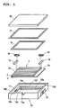
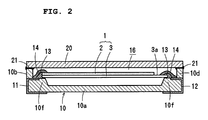
- Figs. 1 and 2 show a piezoelectric sound component, which is one type of surface-mountable electronic component, according to a first preferred embodiment of the present invention.
- the piezoelectric sound component generally includes a unimorph piezoelectric diaphragm 1, a case 10, and a cover 20.
- the piezoelectric diaphragm 1 preferably includes a quadrangular piezoelectric plate 2 and a metal plate 3 preferably having substantially the same width as and a slightly larger length than the piezoelectric plate 2 has.
- the piezoelectric plate 2 has a top electrode 2a and a rear electrode 2b on its top and rear surfaces respectively and is polarized in the thickness direction.
- the rear electrode 2b is bonded to the metal plate 3 so as to oppose each other.
- the piezoelectric plate 2 is bonded to the metal plate 3 so as to be shifted to one side in the length direction of the metal plate 3 and, thus, the metal plate 3 has an exposed portion 3a that is exposed at the other side.
- the piezoelectric plate 2 is preferably formed of a piezoelectric ceramic, such as PZT.
- the metal plate 3 is preferably formed of a conductive, spring-elastic material, and particularly a material with a Young's modulus close to that of the piezoelectric plate 2.
- phosphor bronze or 42Ni is preferably used.
- a metal plate 3 formed of 42Ni has a thermal expansion coefficient close to that of ceramics, such as PZT, accordingly providing higher reliability.
- the diaphragm 1 is housed in the case 10 in such a manner that both the sides of the diaphragm in the length direction are fixed.
- the case 10 is formed of an insulative material, such as ceramic or a resin, in a form preferably having a substantially U-shaped cross section with a bottom 10a and four sidewalls 10b to 10e.
- the case also has a continuous supporting portion 10f for supporting the piezoelectric plate 1 at the inner sides of the sidewalls 10b to 10e.
- the case 10 is, for example, formed by integrally molding a heat-resistant resin, such as LCP, SPS, PPS, or epoxy resin, and particularly a resin having a softening temperature higher than reflow temperature.
- External connection terminals 11 and 12 are insert-molded in the shorter sidewalls 10b and 10d of the case 10 from the upper surfaces of the supporting portion 10f to the bottom surface of the case 10 through the external surfaces of the sidewalls 10b and 10d. Also, a notch 10g, from which sound is released, is formed in the upper side of one sidewall 10c of the longer sidewalls, and a damping hole 10h is formed in the bottom 10a in the vicinity of the other longer sidewall 10e.
- the diaphragm 1 is disposed on the supporting portion 10f of the case 10 such that the metal plate 3 opposes the bottom 10a.
- the shorter sides of the diaphragm 1 are bonded to fix with an insulative adhesive 13 approximately at the centers thereof.
- the insulative adhesive 13 preferably includes an insulative material, such as epoxy resin or urethane. In the present preferred embodiment, a urethane adhesive, which is elastic, is used.
- a conductive adhesive 14 is applied and cured so as to be disposed across the upper surface of the insulative adhesive 13. Consequently, the top electrode 2a is electrically connected to the external terminal 11 at one side of the diaphragm 1, and the exposed portion 3a of the metal plate 3 is electrically connected to the external terminal 12 at the other side.
- the insulative adhesive 13 provides an insulating film over the metal plate 3, thereby preventing a short-circuit resulting from contact of the conductive adhesive 14 with the metal plate 3. Furthermore, the insulative adhesive 13 functions as an elastic body for reducing a stress on the diaphragm 1 resulting from the shrinkage of the conductive adhesive 14 by curing. Then, an elastic sealant 15, such as silicone rubber, is applied to seal between the periphery of the diaphragm 1 and the internal surfaces of the sidewalls of the case 10.
- an elastic sealant 15 such as silicone rubber
- the opening of the case 10 is closed with a cover 20 using an adhesive 21.
- the cover 20 is also formed in a plane, of a material similar to that of the case 10, having a softening temperature lower than the reflow temperature.
- a silicone adhesive, an epoxy adhesive, or any other known adhesive may be used for adhering the cover 20, an acoustic space 16 as shown in Fig. 2 is provided between the cover 20 and the diaphragm 1 and, thus, the surface-mountable piezoelectric sound component is completed.
- the diaphragm 1, whose entire outer region is supported by the case 10, is bending-vibrated to generate a predetermined sound.
- the sound is released to the outside through a sound release defined by the cover 20 and the notch 10g of the case 10.
- the sound release hole may of course be provided in the cover 20, instead of the sidewall of the case 10.
- the diaphragm 1, whose entire outer region is supported by the supporting portion 10f in the present preferred embodiment, may be supported at its two opposing sides or at its four corners so that the other portions are movable.
- the resonance frequency of the diaphragm 1 depends on the shape and area of the supporting portion.
- the piezoelectric sound component is reflow-soldered on a circuit board.
- the case 10 and the cover 20 are differently expanded by heat. This difference in thermal expansion produces stress on the bonded surfaces and, thus, the cover 20 is likely to separate from the case 10 disadvantageously during reflow or in a subsequent drop impact test.
- the case 10 is formed of a resin having a softening temperature higher than the reflow temperature
- the cover 20 is formed of another resin having a softening temperature lower than the reflow temperature, in preferred embodiments of the present invention.
- the difference in thermal expansion by reflow is compensated for by softening the cover 20 to reduce the stress on the bonded portion.
- Figs. 4A, 4B, 5A, and 5B show the results obtained from the measurements of the bonding strengths (tensile strength) before and after reflow between the case 10 and the cover 20.
- a silicon adhesive was used as the adhesive 21 for Figs. 5A and 5B
- an epoxy adhesive was used as the adhesive 21.
- the reflow temperature was set at about 260°C.
- the case measured approximately 12 mm in square by approximately 3 mm in height, with a case wall thickness (adhesion width) of about 0.5 mm and an adhesive thickness of about 0.04 mm.
- Figs. 4A, 4B, 5A, and 5B show the results obtained from the measurements of the bonding strengths (tensile strength) before and after reflow between the case 10 and the cover 20.
- a silicon adhesive was used as the adhesive 21 for Figs. 5A and 5B
- an epoxy adhesive was used as the adhesive 21.
- the reflow temperature was set at about 260°C.
- the case measured
- the case measured approximately 9 mm in square by approximately 3 mm in height, with a case wall thickness (adhesion width) of about 0.3 mm and an adhesive thickness of about 0.04 mm.
- the case and the cover were formed of two types of LCP, namely, types A and B.
- LCP-A has a softening temperature that is higher than the reflow temperature
- LCP-B has a softening temperature that is lower than the reflow temperature.
- Type I refers to the case (comparative example) where LCP-A is used for both the case and the cover;
- Type II the case (an example of preferred embodiments of the present invention) where LCP-A and LCP-B are respectively used for the case and the cover.
- the bonding strength after reflow was reduced in comparison with before reflow in both samples using the silicone adhesive and the epoxy adhesive.
- the bonding strength after reflow was so low as to barely satisfy a strength (10 N) required by drop impact test.
- the sample (present invention) of Type II in which the cover was formed of LCP-B having a lower heat resistance while the case was formed of LCP-A having a higher heat resistance, shows that the bonding strength after reflow was high so as to sufficiently satisfy the required strength.
- the samples using the epoxy adhesive showed substantially the same results as the samples using the silicone adhesive.
- the epoxy adhesive can provide a more reliable package because epoxy adhesives produce a bonding strength (about 30 N to about 40 N) after reflow that is higher than that of silicone adhesives.
- Fig. 6 shows a package structure according to a second preferred embodiment of the present invention.
- the element of the electronic component such as a piezoelectric diaphragm, contained in the case 10 and terminals are omitted from Fig. 6.
- the case 10 had protrusions 10i at the top corners and the cover 20 has cut surfaces 20a at the corners, in order to prevent the cover 20 from being displaced.
- the case 10 and the cover 20 are bonded with a known adhesive, such as an epoxy or a silicone adhesive in the present preferred embodiment as in the first preferred embodiment.
- the case 10 has a softening temperature that is higher than the reflow temperature
- the cover 20 has a softening temperature that is lower than the reflow temperature.
- the softening temperature of the cover 20 that is lower than the reflow temperature reduces the stress, thus preventing the separation of the bonded surfaces and the decrease in bonding strength.
- the protrusions 10i at the corners of the case 10 prevent the cover 20 from shifting in four directions.
- the cases preferably having a substantially U-shaped cross section and the plat covers are used in the foregoing preferred embodiments, they are not limited to these forms.
- the package may include a reverse, substantially U-shaped case and a base plate underlying the case, with an element held in the case and terminal electrodes provided to the base plate.
- both the case and the cover may have a substantially U-shaped cross section, and their open sides may be bonded to each other.
- ultrasonic welding, thermocompression bonding, and other bonding techniques may be applied in addition to using an adhesive.
- the case and the cover are preferably formed of LCP in the foregoing preferred embodiments, another heat-resistant resin, such as SPS, PPS, or epoxy resin, may be used.
- the element of the electronic component is not limited to the diaphragm used in the preferred embodiments described above. Also, the diaphragm is not limited to the unimorph type including a metal plate and a piezoelectric plate bonded to each other, and a bimorph diaphragm may be used which includes ceramic layers with an internal electrode therebetween.
Landscapes
- Engineering & Computer Science (AREA)
- General Engineering & Computer Science (AREA)
- Manufacturing & Machinery (AREA)
- Microelectronics & Electronic Packaging (AREA)
- Physics & Mathematics (AREA)
- Acoustics & Sound (AREA)
- Signal Processing (AREA)
- Casings For Electric Apparatus (AREA)
- Piezo-Electric Transducers For Audible Bands (AREA)
- Piezo-Electric Or Mechanical Vibrators, Or Delay Or Filter Circuits (AREA)
- Surface Acoustic Wave Elements And Circuit Networks Thereof (AREA)
Abstract
Description
Claims (10)
- A package of a surface-mountable electronic component to be reflow-soldered to a circuit board at a reflow temperature of about 250°C or more, the package comprising:a case with an opening, holding an element of the electronic component therein, the case having a softening temperature that is higher than the reflow temperature; anda cover bonded to the case so as to close the opening, the cover having a softening temperature that is lower than the reflow temperature.
- The package according to Claim 1, wherein each of the case and the cover includes a liquid crystal polymer.
- The package according to Claim 1 or 2, wherein the softening temperature of the cover is in the range of about 180°C to about 240°C.
- The package according to Claim 1, 2 or 3, wherein the case and the cover are bonded to each other with an epoxy adhesive.
- The package according to Claim 1, 2 or 3, wherein the case and the cover are bonded to each other with a silicon adhesive.
- The package according to any preceding claim, wherein the element is a piezoelectric diaphragm which is bending-vibrated in response to application of an alternate signal, the case has a pair of terminals fixed thereto for applying the alternate signal to the piezoelectric diaphragm, and at least one of the case and the cover has a sound release hole through which sound is released.
- The package according to any of claims 1 to 5, wherein the element is a unimorph piezoelectric diaphragm.
- The package according to any of claims 1 to 5, wherein the element is a piezoelectric diaphragm which includes a quadrangular piezoelectric plate and a metal plate.
- The package according to Claim 1, wherein the case includes protrusions at top corners thereof.
- The package according to Claim 1, wherein the cover has cut surfaces at corners thereof.
Applications Claiming Priority (4)
| Application Number | Priority Date | Filing Date | Title |
|---|---|---|---|
| JP2003118025 | 2003-04-23 | ||
| JP2003118025 | 2003-04-23 | ||
| JP2003427166 | 2003-12-24 | ||
| JP2003427166A JP3972900B2 (en) | 2003-04-23 | 2003-12-24 | Housing structure for surface mount electronic components |
Publications (3)
| Publication Number | Publication Date |
|---|---|
| EP1471769A2 true EP1471769A2 (en) | 2004-10-27 |
| EP1471769A3 EP1471769A3 (en) | 2009-11-18 |
| EP1471769B1 EP1471769B1 (en) | 2011-11-02 |
Family
ID=32964972
Family Applications (1)
| Application Number | Title | Priority Date | Filing Date |
|---|---|---|---|
| EP04250778A Expired - Lifetime EP1471769B1 (en) | 2003-04-23 | 2004-02-13 | Surface-mountable electronic component |
Country Status (7)
| Country | Link |
|---|---|
| US (1) | US7583011B2 (en) |
| EP (1) | EP1471769B1 (en) |
| JP (1) | JP3972900B2 (en) |
| KR (1) | KR100608448B1 (en) |
| CN (1) | CN100385999C (en) |
| AT (1) | ATE532347T1 (en) |
| TW (1) | TWI237513B (en) |
Cited By (1)
| Publication number | Priority date | Publication date | Assignee | Title |
|---|---|---|---|---|
| EP1689079A3 (en) * | 2005-02-03 | 2007-11-07 | Epson Toyocom Corporation | Piezoelectric vibration element, piezoelectric vibrator, piezoelectric oscillator, frequency stabilization method, and method of manufacturing the piezoelectric vibrator |
Families Citing this family (21)
| Publication number | Priority date | Publication date | Assignee | Title |
|---|---|---|---|---|
| JP2004015768A (en) * | 2002-06-12 | 2004-01-15 | Murata Mfg Co Ltd | Piezoelectric electroacoustic transducer |
| JP2009177744A (en) * | 2008-01-28 | 2009-08-06 | Panasonic Electric Works Co Ltd | Acoustic module housing joining method |
| TWI455602B (en) * | 2009-01-27 | 2014-10-01 | Taiyo Yuden Kk | Piezoelectric body |
| TWI379331B (en) * | 2009-02-09 | 2012-12-11 | Delta Electronics Inc | Surface mount magnetic device and pick and place method using the same |
| TW201125372A (en) * | 2010-01-15 | 2011-07-16 | Univ Nat Chiao Tung | Piezoelectric panel speaker and optimal design method of the same |
| JP5026574B2 (en) * | 2010-04-27 | 2012-09-12 | 日本電波工業株式会社 | Piezoelectric device |
| JP5654300B2 (en) | 2010-09-17 | 2015-01-14 | ポリプラスチックス株式会社 | Integrated molded body |
| JP5650496B2 (en) | 2010-10-28 | 2015-01-07 | ウィンテックポリマー株式会社 | Integrated molded body |
| CN102593077A (en) * | 2011-01-14 | 2012-07-18 | 美新半导体(无锡)有限公司 | Liquid crystal polymer (LCP) encapsulating structure and manufacturing method thereof |
| DE102011079646A1 (en) * | 2011-07-22 | 2013-02-07 | Robert Bosch Gmbh | Ultrasonic sensor device for detecting and / or transmitting ultrasound |
| DE102012202727B4 (en) * | 2012-02-22 | 2015-07-02 | Vectron International Gmbh | Method for connecting a first electronic component to a second component |
| CN103868626B (en) * | 2012-12-18 | 2017-07-11 | 杭州三花研究院有限公司 | A kind of transducer and calorimeter |
| TWI527471B (en) | 2014-03-14 | 2016-03-21 | 財團法人工業技術研究院 | Piezoelectric electroacoustic transducer |
| JP2015177422A (en) * | 2014-03-17 | 2015-10-05 | 京セラ株式会社 | Sound generator, sound generator, electronic device, and portable terminal |
| TWI533714B (en) | 2014-04-18 | 2016-05-11 | 財團法人工業技術研究院 | Piezoelectric electroacoustic transducer |
| JP6222185B2 (en) * | 2015-08-11 | 2017-11-01 | Tdk株式会社 | Piezoelectric sounding body |
| KR102002805B1 (en) * | 2018-02-02 | 2019-07-23 | (주)와이솔 | Housing assembly comprising piezoelectric speaker unit to be installed on mobile terminal |
| CN210958415U (en) * | 2019-07-17 | 2020-07-07 | 华为技术有限公司 | Center, battery cover and electronic equipment |
| US12514127B2 (en) * | 2021-01-25 | 2025-12-30 | Seiko Epson Corporation | Electronic device and method for manufacturing electronic device |
| EP4307358A1 (en) * | 2021-03-09 | 2024-01-17 | Tomoegawa Co., Ltd. | Electronic component sealing lid |
| US20240145320A1 (en) * | 2021-03-09 | 2024-05-02 | Tomoegawa Co., Ltd | Electronic component sealing lid |
Family Cites Families (12)
| Publication number | Priority date | Publication date | Assignee | Title |
|---|---|---|---|---|
| US4403695A (en) * | 1982-01-06 | 1983-09-13 | Hallmark Cards, Inc. | Heat-shrinkable film wrapped packaging |
| JP2907914B2 (en) * | 1989-01-16 | 1999-06-21 | シーメンス、アクチエンゲゼルシヤフト | Sealing method and package for electric or electronic device or module |
| JPH08340184A (en) * | 1995-06-13 | 1996-12-24 | Shimeo Seimitsu Kk | Electronic component storage container |
| US5860583A (en) * | 1996-07-01 | 1999-01-19 | Motorola, Inc. | Evaporative cooling vessel for controlling the temperature of a portion of an electronic part during solder reflow |
| FR2762586B1 (en) * | 1997-04-24 | 1999-07-16 | Otor Sa | PACKAGING, BLANK ASSEMBLY, METHOD AND DEVICE FOR PACKAGING AN ARTICLE OR A LOT OF ARTICLES OF UNDERMINED VOLUME |
| EP0951068A1 (en) * | 1998-04-17 | 1999-10-20 | Interuniversitair Micro-Elektronica Centrum Vzw | Method of fabrication of a microstructure having an inside cavity |
| JP3436205B2 (en) | 1999-02-22 | 2003-08-11 | 株式会社村田製作所 | Piezo acoustic components |
| JP3489509B2 (en) * | 1999-02-22 | 2004-01-19 | 株式会社村田製作所 | Electroacoustic transducer |
| JP3339450B2 (en) * | 1999-03-02 | 2002-10-28 | 株式会社村田製作所 | Method for manufacturing surface acoustic wave device |
| US6653762B2 (en) * | 2000-04-19 | 2003-11-25 | Murata Manufacturing Co., Ltd. | Piezoelectric type electric acoustic converter |
| JP4111678B2 (en) | 2001-01-31 | 2008-07-02 | 三洋電機株式会社 | Electrochemical device for surface mounting and manufacturing method thereof |
| US6599775B2 (en) * | 2001-05-18 | 2003-07-29 | Advanpack Solutions Pte Ltd | Method for forming a flip chip semiconductor package, a semiconductor package formed thereby, and a substrate therefor |
-
2003
- 2003-12-24 JP JP2003427166A patent/JP3972900B2/en not_active Expired - Fee Related
-
2004
- 2004-02-03 US US10/770,763 patent/US7583011B2/en active Active
- 2004-02-04 TW TW093102485A patent/TWI237513B/en not_active IP Right Cessation
- 2004-02-13 AT AT04250778T patent/ATE532347T1/en active
- 2004-02-13 EP EP04250778A patent/EP1471769B1/en not_active Expired - Lifetime
- 2004-02-23 CN CNB2004100059815A patent/CN100385999C/en not_active Expired - Fee Related
- 2004-04-22 KR KR1020040027788A patent/KR100608448B1/en not_active Expired - Fee Related
Cited By (5)
| Publication number | Priority date | Publication date | Assignee | Title |
|---|---|---|---|---|
| EP1689079A3 (en) * | 2005-02-03 | 2007-11-07 | Epson Toyocom Corporation | Piezoelectric vibration element, piezoelectric vibrator, piezoelectric oscillator, frequency stabilization method, and method of manufacturing the piezoelectric vibrator |
| US7427823B2 (en) | 2005-02-03 | 2008-09-23 | Epson Toyocom Corporation | Piezoelectric vibration element, piezoelectric vibrator, piezoelectric oscillator, frequency stabilization method, and method of manufacturing the piezoelectric vibrator |
| US8166621B2 (en) | 2005-02-03 | 2012-05-01 | Seiko Epson Corporation | Method of stabilizing a frequency of a piezoelectric vibration element |
| US8281467B2 (en) | 2005-02-03 | 2012-10-09 | Seiko Epson Corporation | Method of manufacturing a piezoelectric vibrator |
| US8732924B2 (en) | 2005-02-03 | 2014-05-27 | Seiko Epson Corporation | Method of manufacturing a piezoelectric vibrator |
Also Published As
| Publication number | Publication date |
|---|---|
| CN100385999C (en) | 2008-04-30 |
| EP1471769A3 (en) | 2009-11-18 |
| JP2004343684A (en) | 2004-12-02 |
| ATE532347T1 (en) | 2011-11-15 |
| EP1471769B1 (en) | 2011-11-02 |
| TW200423787A (en) | 2004-11-01 |
| CN1541026A (en) | 2004-10-27 |
| TWI237513B (en) | 2005-08-01 |
| US20040218769A1 (en) | 2004-11-04 |
| KR20040092460A (en) | 2004-11-03 |
| KR100608448B1 (en) | 2006-08-03 |
| JP3972900B2 (en) | 2007-09-05 |
| US7583011B2 (en) | 2009-09-01 |
Similar Documents
| Publication | Publication Date | Title |
|---|---|---|
| US7583011B2 (en) | Package of surface-mountable electronic component | |
| US6472798B2 (en) | Piezoelectric acoustic components | |
| KR100488335B1 (en) | Piezoelectric electroacoustic transducer | |
| US6590315B2 (en) | Surface mount quartz crystal resonators and methods for making same | |
| US6960868B2 (en) | Piezoelectric electro-acoustic transducer and manufacturing method of the same | |
| US6894423B2 (en) | Piezoelectric electroacoustic transducer | |
| US7259502B2 (en) | Insert terminal-containing case, piezoelectric electroacoustic transducer using the same, and process for producing insert terminal-containing case | |
| WO2005064989A1 (en) | Piezoelectric electro-acoustic converter | |
| JP3436205B2 (en) | Piezo acoustic components | |
| US6794799B2 (en) | Piezoelectric electroacoustic transducer | |
| JP3427032B2 (en) | Electret condenser microphone | |
| KR20060060680A (en) | Piezoelectric Acoustic Transducer | |
| US20040041497A1 (en) | Piezoelectric sounding body and piezoelectric electroacoustic transducer using the same | |
| JPH11234077A (en) | Surface mounted piezoelectric part | |
| JP2002238094A (en) | Piezoelectric acoustic part and method for manufacturing the same | |
| JP2001244781A (en) | Surface acoustic wave device | |
| JPH02112308A (en) | Small type piezoelectric vibrator unit |
Legal Events
| Date | Code | Title | Description |
|---|---|---|---|
| PUAI | Public reference made under article 153(3) epc to a published international application that has entered the european phase |
Free format text: ORIGINAL CODE: 0009012 |
|
| 17P | Request for examination filed |
Effective date: 20040305 |
|
| AK | Designated contracting states |
Kind code of ref document: A2 Designated state(s): AT BE BG CH CY CZ DE DK EE ES FI FR GB GR HU IE IT LI LU MC NL PT RO SE SI SK TR |
|
| AX | Request for extension of the european patent |
Extension state: AL LT LV MK |
|
| RAP1 | Party data changed (applicant data changed or rights of an application transferred) |
Owner name: MURATA MANUFACTURING CO., LTD. |
|
| PUAL | Search report despatched |
Free format text: ORIGINAL CODE: 0009013 |
|
| AK | Designated contracting states |
Kind code of ref document: A3 Designated state(s): AT BE BG CH CY CZ DE DK EE ES FI FR GB GR HU IE IT LI LU MC NL PT RO SE SI SK TR |
|
| AX | Request for extension of the european patent |
Extension state: AL LT LV MK |
|
| AKX | Designation fees paid |
Designated state(s): AT BE BG CH CY CZ DE DK EE ES FI FR GB GR HU IE IT LI LU MC NL PT RO SE SI SK TR |
|
| GRAP | Despatch of communication of intention to grant a patent |
Free format text: ORIGINAL CODE: EPIDOSNIGR1 |
|
| GRAS | Grant fee paid |
Free format text: ORIGINAL CODE: EPIDOSNIGR3 |
|
| GRAA | (expected) grant |
Free format text: ORIGINAL CODE: 0009210 |
|
| AK | Designated contracting states |
Kind code of ref document: B1 Designated state(s): AT BE BG CH CY CZ DE DK EE ES FI FR GB GR HU IE IT LI LU MC NL PT RO SE SI SK TR |
|
| REG | Reference to a national code |
Ref country code: GB Ref legal event code: FG4D |
|
| REG | Reference to a national code |
Ref country code: CH Ref legal event code: EP |
|
| REG | Reference to a national code |
Ref country code: IE Ref legal event code: FG4D |
|
| REG | Reference to a national code |
Ref country code: DE Ref legal event code: R096 Ref document number: 602004035091 Country of ref document: DE Effective date: 20120112 |
|
| REG | Reference to a national code |
Ref country code: NL Ref legal event code: VDEP Effective date: 20111102 |
|
| PG25 | Lapsed in a contracting state [announced via postgrant information from national office to epo] |
Ref country code: PT Free format text: LAPSE BECAUSE OF FAILURE TO SUBMIT A TRANSLATION OF THE DESCRIPTION OR TO PAY THE FEE WITHIN THE PRESCRIBED TIME-LIMIT Effective date: 20120302 Ref country code: NL Free format text: LAPSE BECAUSE OF FAILURE TO SUBMIT A TRANSLATION OF THE DESCRIPTION OR TO PAY THE FEE WITHIN THE PRESCRIBED TIME-LIMIT Effective date: 20111102 Ref country code: GR Free format text: LAPSE BECAUSE OF FAILURE TO SUBMIT A TRANSLATION OF THE DESCRIPTION OR TO PAY THE FEE WITHIN THE PRESCRIBED TIME-LIMIT Effective date: 20120203 Ref country code: BE Free format text: LAPSE BECAUSE OF FAILURE TO SUBMIT A TRANSLATION OF THE DESCRIPTION OR TO PAY THE FEE WITHIN THE PRESCRIBED TIME-LIMIT Effective date: 20111102 Ref country code: SI Free format text: LAPSE BECAUSE OF FAILURE TO SUBMIT A TRANSLATION OF THE DESCRIPTION OR TO PAY THE FEE WITHIN THE PRESCRIBED TIME-LIMIT Effective date: 20111102 Ref country code: SE Free format text: LAPSE BECAUSE OF FAILURE TO SUBMIT A TRANSLATION OF THE DESCRIPTION OR TO PAY THE FEE WITHIN THE PRESCRIBED TIME-LIMIT Effective date: 20111102 |
|
| PG25 | Lapsed in a contracting state [announced via postgrant information from national office to epo] |
Ref country code: CY Free format text: LAPSE BECAUSE OF FAILURE TO SUBMIT A TRANSLATION OF THE DESCRIPTION OR TO PAY THE FEE WITHIN THE PRESCRIBED TIME-LIMIT Effective date: 20111102 |
|
| PG25 | Lapsed in a contracting state [announced via postgrant information from national office to epo] |
Ref country code: BG Free format text: LAPSE BECAUSE OF FAILURE TO SUBMIT A TRANSLATION OF THE DESCRIPTION OR TO PAY THE FEE WITHIN THE PRESCRIBED TIME-LIMIT Effective date: 20120202 Ref country code: DK Free format text: LAPSE BECAUSE OF FAILURE TO SUBMIT A TRANSLATION OF THE DESCRIPTION OR TO PAY THE FEE WITHIN THE PRESCRIBED TIME-LIMIT Effective date: 20111102 Ref country code: EE Free format text: LAPSE BECAUSE OF FAILURE TO SUBMIT A TRANSLATION OF THE DESCRIPTION OR TO PAY THE FEE WITHIN THE PRESCRIBED TIME-LIMIT Effective date: 20111102 Ref country code: CZ Free format text: LAPSE BECAUSE OF FAILURE TO SUBMIT A TRANSLATION OF THE DESCRIPTION OR TO PAY THE FEE WITHIN THE PRESCRIBED TIME-LIMIT Effective date: 20111102 Ref country code: SK Free format text: LAPSE BECAUSE OF FAILURE TO SUBMIT A TRANSLATION OF THE DESCRIPTION OR TO PAY THE FEE WITHIN THE PRESCRIBED TIME-LIMIT Effective date: 20111102 |
|
| PG25 | Lapsed in a contracting state [announced via postgrant information from national office to epo] |
Ref country code: RO Free format text: LAPSE BECAUSE OF FAILURE TO SUBMIT A TRANSLATION OF THE DESCRIPTION OR TO PAY THE FEE WITHIN THE PRESCRIBED TIME-LIMIT Effective date: 20111102 Ref country code: IT Free format text: LAPSE BECAUSE OF FAILURE TO SUBMIT A TRANSLATION OF THE DESCRIPTION OR TO PAY THE FEE WITHIN THE PRESCRIBED TIME-LIMIT Effective date: 20111102 |
|
| PLBE | No opposition filed within time limit |
Free format text: ORIGINAL CODE: 0009261 |
|
| STAA | Information on the status of an ep patent application or granted ep patent |
Free format text: STATUS: NO OPPOSITION FILED WITHIN TIME LIMIT |
|
| REG | Reference to a national code |
Ref country code: AT Ref legal event code: MK05 Ref document number: 532347 Country of ref document: AT Kind code of ref document: T Effective date: 20111102 |
|
| PG25 | Lapsed in a contracting state [announced via postgrant information from national office to epo] |
Ref country code: MC Free format text: LAPSE BECAUSE OF NON-PAYMENT OF DUE FEES Effective date: 20120229 |
|
| REG | Reference to a national code |
Ref country code: CH Ref legal event code: PL |
|
| 26N | No opposition filed |
Effective date: 20120803 |
|
| GBPC | Gb: european patent ceased through non-payment of renewal fee |
Effective date: 20120213 |
|
| PG25 | Lapsed in a contracting state [announced via postgrant information from national office to epo] |
Ref country code: CH Free format text: LAPSE BECAUSE OF NON-PAYMENT OF DUE FEES Effective date: 20120229 Ref country code: LI Free format text: LAPSE BECAUSE OF NON-PAYMENT OF DUE FEES Effective date: 20120229 |
|
| REG | Reference to a national code |
Ref country code: IE Ref legal event code: MM4A |
|
| REG | Reference to a national code |
Ref country code: FR Ref legal event code: ST Effective date: 20121031 |
|
| REG | Reference to a national code |
Ref country code: DE Ref legal event code: R097 Ref document number: 602004035091 Country of ref document: DE Effective date: 20120803 |
|
| PG25 | Lapsed in a contracting state [announced via postgrant information from national office to epo] |
Ref country code: GB Free format text: LAPSE BECAUSE OF NON-PAYMENT OF DUE FEES Effective date: 20120213 Ref country code: AT Free format text: LAPSE BECAUSE OF FAILURE TO SUBMIT A TRANSLATION OF THE DESCRIPTION OR TO PAY THE FEE WITHIN THE PRESCRIBED TIME-LIMIT Effective date: 20111102 Ref country code: IE Free format text: LAPSE BECAUSE OF NON-PAYMENT OF DUE FEES Effective date: 20120213 Ref country code: FR Free format text: LAPSE BECAUSE OF NON-PAYMENT OF DUE FEES Effective date: 20120229 |
|
| PG25 | Lapsed in a contracting state [announced via postgrant information from national office to epo] |
Ref country code: ES Free format text: LAPSE BECAUSE OF FAILURE TO SUBMIT A TRANSLATION OF THE DESCRIPTION OR TO PAY THE FEE WITHIN THE PRESCRIBED TIME-LIMIT Effective date: 20120213 |
|
| PG25 | Lapsed in a contracting state [announced via postgrant information from national office to epo] |
Ref country code: FI Free format text: LAPSE BECAUSE OF FAILURE TO SUBMIT A TRANSLATION OF THE DESCRIPTION OR TO PAY THE FEE WITHIN THE PRESCRIBED TIME-LIMIT Effective date: 20111102 |
|
| PG25 | Lapsed in a contracting state [announced via postgrant information from national office to epo] |
Ref country code: TR Free format text: LAPSE BECAUSE OF FAILURE TO SUBMIT A TRANSLATION OF THE DESCRIPTION OR TO PAY THE FEE WITHIN THE PRESCRIBED TIME-LIMIT Effective date: 20111102 |
|
| PG25 | Lapsed in a contracting state [announced via postgrant information from national office to epo] |
Ref country code: LU Free format text: LAPSE BECAUSE OF NON-PAYMENT OF DUE FEES Effective date: 20120213 |
|
| PG25 | Lapsed in a contracting state [announced via postgrant information from national office to epo] |
Ref country code: HU Free format text: LAPSE BECAUSE OF FAILURE TO SUBMIT A TRANSLATION OF THE DESCRIPTION OR TO PAY THE FEE WITHIN THE PRESCRIBED TIME-LIMIT Effective date: 20040213 |
|
| PGFP | Annual fee paid to national office [announced via postgrant information from national office to epo] |
Ref country code: DE Payment date: 20220217 Year of fee payment: 19 |
|
| REG | Reference to a national code |
Ref country code: DE Ref legal event code: R119 Ref document number: 602004035091 Country of ref document: DE |
|
| PG25 | Lapsed in a contracting state [announced via postgrant information from national office to epo] |
Ref country code: DE Free format text: LAPSE BECAUSE OF NON-PAYMENT OF DUE FEES Effective date: 20230901 |