EP1471767A2 - Method and system for acoustic shock protection - Google Patents
Method and system for acoustic shock protection Download PDFInfo
- Publication number
- EP1471767A2 EP1471767A2 EP04007864A EP04007864A EP1471767A2 EP 1471767 A2 EP1471767 A2 EP 1471767A2 EP 04007864 A EP04007864 A EP 04007864A EP 04007864 A EP04007864 A EP 04007864A EP 1471767 A2 EP1471767 A2 EP 1471767A2
- Authority
- EP
- European Patent Office
- Prior art keywords
- shock
- band
- signal
- module
- sub
- Prior art date
- Legal status (The legal status is an assumption and is not a legal conclusion. Google has not performed a legal analysis and makes no representation as to the accuracy of the status listed.)
- Granted
Links
- 206010068150 Acoustic shock Diseases 0.000 title claims abstract description 90
- 238000000034 method Methods 0.000 title claims abstract description 44
- 238000004458 analytical method Methods 0.000 claims abstract description 74
- 238000000605 extraction Methods 0.000 claims abstract description 34
- 230000035939 shock Effects 0.000 claims description 113
- 238000001514 detection method Methods 0.000 claims description 40
- 238000012545 processing Methods 0.000 claims description 30
- 230000000737 periodic effect Effects 0.000 claims description 20
- 230000003044 adaptive effect Effects 0.000 claims description 18
- 230000015572 biosynthetic process Effects 0.000 claims description 15
- 238000003786 synthesis reaction Methods 0.000 claims description 15
- 238000001914 filtration Methods 0.000 claims description 9
- 230000003111 delayed effect Effects 0.000 claims description 5
- 230000001131 transforming effect Effects 0.000 claims description 5
- 230000008569 process Effects 0.000 claims description 4
- 230000002194 synthesizing effect Effects 0.000 claims description 4
- 238000013480 data collection Methods 0.000 claims description 3
- 238000013459 approach Methods 0.000 abstract description 14
- 238000005259 measurement Methods 0.000 description 47
- 238000004364 calculation method Methods 0.000 description 15
- 230000001052 transient effect Effects 0.000 description 14
- 238000010586 diagram Methods 0.000 description 9
- 230000000875 corresponding effect Effects 0.000 description 7
- 230000006870 function Effects 0.000 description 7
- 230000004044 response Effects 0.000 description 4
- 230000002411 adverse Effects 0.000 description 3
- 238000013528 artificial neural network Methods 0.000 description 3
- 230000001419 dependent effect Effects 0.000 description 3
- 230000009977 dual effect Effects 0.000 description 3
- 230000007774 longterm Effects 0.000 description 3
- 206010011878 Deafness Diseases 0.000 description 2
- 206010070834 Sensitisation Diseases 0.000 description 2
- 230000006835 compression Effects 0.000 description 2
- 238000007906 compression Methods 0.000 description 2
- 230000002596 correlated effect Effects 0.000 description 2
- 238000005516 engineering process Methods 0.000 description 2
- 231100000888 hearing loss Toxicity 0.000 description 2
- 230000010370 hearing loss Effects 0.000 description 2
- 208000016354 hearing loss disease Diseases 0.000 description 2
- 238000000691 measurement method Methods 0.000 description 2
- 230000009467 reduction Effects 0.000 description 2
- 230000008313 sensitization Effects 0.000 description 2
- 230000005236 sound signal Effects 0.000 description 2
- 230000003068 static effect Effects 0.000 description 2
- 238000012935 Averaging Methods 0.000 description 1
- 206010006784 Burning sensation Diseases 0.000 description 1
- 208000002193 Pain Diseases 0.000 description 1
- 208000009205 Tinnitus Diseases 0.000 description 1
- 208000012886 Vertigo Diseases 0.000 description 1
- 230000003213 activating effect Effects 0.000 description 1
- 230000006399 behavior Effects 0.000 description 1
- 230000008901 benefit Effects 0.000 description 1
- 230000015556 catabolic process Effects 0.000 description 1
- 238000006243 chemical reaction Methods 0.000 description 1
- 238000004891 communication Methods 0.000 description 1
- 230000000052 comparative effect Effects 0.000 description 1
- 230000000295 complement effect Effects 0.000 description 1
- 238000006731 degradation reaction Methods 0.000 description 1
- 238000011161 development Methods 0.000 description 1
- 210000005069 ears Anatomy 0.000 description 1
- 230000000694 effects Effects 0.000 description 1
- 239000000284 extract Substances 0.000 description 1
- 230000003116 impacting effect Effects 0.000 description 1
- 230000000977 initiatory effect Effects 0.000 description 1
- 208000014674 injury Diseases 0.000 description 1
- 238000002955 isolation Methods 0.000 description 1
- 230000007246 mechanism Effects 0.000 description 1
- 238000012986 modification Methods 0.000 description 1
- 230000004048 modification Effects 0.000 description 1
- 210000003205 muscle Anatomy 0.000 description 1
- 238000005086 pumping Methods 0.000 description 1
- 230000011514 reflex Effects 0.000 description 1
- 238000012552 review Methods 0.000 description 1
- 238000001228 spectrum Methods 0.000 description 1
- 208000024891 symptom Diseases 0.000 description 1
- 208000011580 syndromic disease Diseases 0.000 description 1
- 231100000886 tinnitus Toxicity 0.000 description 1
- 238000012549 training Methods 0.000 description 1
- 230000007704 transition Effects 0.000 description 1
- 230000008733 trauma Effects 0.000 description 1
- 231100000889 vertigo Toxicity 0.000 description 1
Images


Classifications
-
- H—ELECTRICITY
- H03—ELECTRONIC CIRCUITRY
- H03G—CONTROL OF AMPLIFICATION
- H03G7/00—Volume compression or expansion in amplifiers
- H03G7/002—Volume compression or expansion in amplifiers in untuned or low-frequency amplifiers, e.g. audio amplifiers
-
- A—HUMAN NECESSITIES
- A61—MEDICAL OR VETERINARY SCIENCE; HYGIENE
- A61F—FILTERS IMPLANTABLE INTO BLOOD VESSELS; PROSTHESES; DEVICES PROVIDING PATENCY TO, OR PREVENTING COLLAPSING OF, TUBULAR STRUCTURES OF THE BODY, e.g. STENTS; ORTHOPAEDIC, NURSING OR CONTRACEPTIVE DEVICES; FOMENTATION; TREATMENT OR PROTECTION OF EYES OR EARS; BANDAGES, DRESSINGS OR ABSORBENT PADS; FIRST-AID KITS
- A61F11/00—Methods or devices for treatment of the ears or hearing sense; Non-electric hearing aids; Methods or devices for enabling ear patients to achieve auditory perception through physiological senses other than hearing sense; Protective devices for the ears, carried on the body or in the hand
- A61F11/06—Protective devices for the ears
- A61F11/14—Protective devices for the ears external, e.g. earcaps or earmuffs
- A61F11/145—Protective devices for the ears external, e.g. earcaps or earmuffs electric, e.g. for active noise reduction
-
- H—ELECTRICITY
- H04—ELECTRIC COMMUNICATION TECHNIQUE
- H04R—LOUDSPEAKERS, MICROPHONES, GRAMOPHONE PICK-UPS OR LIKE ACOUSTIC ELECTROMECHANICAL TRANSDUCERS; DEAF-AID SETS; PUBLIC ADDRESS SYSTEMS
- H04R25/00—Deaf-aid sets, i.e. electro-acoustic or electro-mechanical hearing aids; Electric tinnitus maskers providing an auditory perception
- H04R25/45—Prevention of acoustic reaction, i.e. acoustic oscillatory feedback
- H04R25/453—Prevention of acoustic reaction, i.e. acoustic oscillatory feedback electronically
-
- H—ELECTRICITY
- H04—ELECTRIC COMMUNICATION TECHNIQUE
- H04R—LOUDSPEAKERS, MICROPHONES, GRAMOPHONE PICK-UPS OR LIKE ACOUSTIC ELECTROMECHANICAL TRANSDUCERS; DEAF-AID SETS; PUBLIC ADDRESS SYSTEMS
- H04R3/00—Circuits for transducers, loudspeakers or microphones
- H04R3/02—Circuits for transducers, loudspeakers or microphones for preventing acoustic reaction, i.e. acoustic oscillatory feedback
Definitions
- This invention relates to signal processing technology, and more particularly, to a method and system for acoustic shock protection.
- Unwanted sounds such as loud sounds or sounds that have a rapid relative increase in level, may be produced by telephone or radio systems, intentionally or unintentionally. Those sounds are typically experienced by a user through headphones or a headset.
- acoustic shock may result in permanent hearing loss, temporary hearing loss and tinnitus (constant ringing in the ears). Sufferers also report symptoms including extreme pain, vertigo and burning sensations.
- acoustic shock syndrome apart from the initial high-level sound, is the startle reflex action. This reaction can cause numerous muscles to activate to an unusual degree.
- the processed output signal of those devices has reduced fidelity compared to an input signal.
- Typical distortions of the signal include: "pumping” (unnecessary and audible adjustments of the gain that adversely affect the perceived quality of the processed speech signal) and "holes” (audio dropouts in the processed signal caused by extreme gain adjustments), harmonic distortion as well as the accompanying intermodulation distortion that comes from poor gain control.
- More complex systems may also suffer from excessive input-output latency (i.e., group delay), which can adversely impact network, acoustic and line echo cancellers.
- a method of providing protection against acoustic shock which includes the steps of: performing a pattern analysis on an input signal to identify a parameter space corresponding to a signal space of the input signal; applying a rule-based decision to the parameter space to detect an acoustic shock event; and removing the acoustic shock event from the input signal to generate a processed output signal.
- a method of providing protection against acoustic shock which includes the steps of: performing a weighted overlap-add (WOLA) analysis on an input signal; performing feature extraction on the input signal and performing feature extraction on the plurality of band signals provided by the WOLA analysis; detecting an acoustic shock event based on feature extractions from the input signal and band signals; performing gain control based on the acoustic shock event detection; applying a plurality of calibrated gains to the band signals to reduce the level to meet a predetermined safe level; and performing a WOLA synthesis on the modified band signals (modified by the application of gain) to synthesize an output signal.
- WOLA weighted overlap-add
- a system for providing protection against acoustic shock which includes: an analysis module for performing a pattern analysis on an input signal to identify a parameter space corresponding to a signal space of the input signal; a detection module for applying a rule-based decision to the parameter space to detect an acoustic shock event; and a removal module for removing the acoustic shock event.
- a system for providing protection against acoustic shock which includes: a weighted overlap add (WOLA) analysis module for transforming an input signal to a plurality of band signals; a feature extraction module for performing feature extraction on the input signal and for performing feature extraction on the band signals; a detection module for detecting an acoustic shock event based on the feature extractions from the input signal and the band signals; a gain control module for performing gain control based on the shock detection and the extracted features of the input signal and the band signals; and a calibration module for applying calibrated gains to the band signals to reduce the level to meet a predetermined safe level; and a WOLA synthesis module for synthesizing the modified band signals to provide an output signal.
- WOLA weighted overlap add
- a system for providing protection against an acoustic shock which includes: a weighted overlap-add (WOLA) analysis module for transforming an input signal into a plurality of oversampled sub-band signals in a frequency domain; a processing module for adaptively processing the sub-band signals to remove an acoustic shock event: and a WOLA synthesis module for synthesizing the processed sub-band signals to provide an output signal.
- WOLA weighted overlap-add
- an acoustic shock protection method and system in which a weighted overlap-add (WOLA) filterbank is used and a delay unit is used prior to WOLA analysis enabling predictive features to be fed around the WOLA filterbank analysis stage.
- WOLA weighted overlap-add
- the inherent delay of the WOLA analysis filterbank processing is advantageously used; reducing the necessary amount of added delay while maintaining a low overall group delay.
- the low group delay of the WOLA filterbank is a considerable advantage.
- FIG. 1 shows an acoustic shock protection system 2 in accordance with an embodiment of the present invention.
- the acoustic shock protection system 2 includes an analysis block 4, a detection block 6, a removal block 8 and a logging block 10.
- the system 2 further includes a calibration block 12 that contains data used to calibrate the input and output levels and to support user preferences (e.g. support for personalization).
- the arrows in Figure 1 show how these major blocks interconnect and interact with each other.
- the acoustic shock protection system 2 implements a pattern analysis-based approach.
- the approach employs a collection of input signals, referred to as a "signal space", which contains a representative subset of acoustic shock and non-acoustic shock signals that the system will process and, in the case of input signals that contain an acoustic shock event, protect against in typical operation.
- This signal space is processed via a feature extraction process at the analysis block 4 to realize a reduced dataset representation of the signal space.
- the collection of reduced dataset representations, one for each of the signals in the signal space is referred to as a parameter space.
- the feature extraction process includes one or more measurements.
- the pattern analysis-based approach uses the measurements to determine if an acoustic shock is present.
- the acoustic shocks may include high level, short duration (e.g. a loud sound); level versus time exposure; rapid increase in relative level exposure and/or combination thereof.
- the analysis block 4 may use, for example, artificial neural networks, hidden Markov models, Bayesian estimation methods, signal statistics or combinations of signal parameters such as short-term and long-term level over various frequency ranges and time-scales. In some situations, it may be necessary to measure and protect against level versus time exposure to signal levels. In combination with the other subcomponents of the analysis block 4, a timer component 14 in the analysis block 4 provides the capability to protect against level-over-time exposure.
- the detection block 6 contains a logical description in terms of inference rules representing patterns of analysis output conditions representing acoustic shock events.
- the detection block 6, for example, may take the form of a rule-based expert system.
- the removal block 8 implements the signal processing necessary to remove the shock event from the input signal, typically by the application of time, level or frequency-dependent gain or a combination thereof, while maintaining the fidelity of the output signal, relative to the input signal.
- the logging block 10 implements on-line data collection of the key parameters of shock events. This information is time-stamped using the timer 14 or another similar means and may be categorized to provide accurate data records for later downloading and analysis.
- the calibration block 12 provides data that is required to account for the acoustic and electrical differences between various headphones, headsets, systems and other components.
- the data from the block 12 ensures that the output level experienced by the user of the system 2 does not exceed a preset maximum as a function of time and frequency.
- the preset maximum may be changeable for each user.
- the logging block 10 and the calibration block 12 may be detachably attached to the system 2.
- the analysis block 4, the detection block 6 and the removal block 8 are shown separately. However, the component of the analysis block 4 may be used as the component of the detection block 6 or the removal block 8. The component of the detection block 6 may be used as the component of the removal block 8. Processing done in each of the blocks may be reused in other blocks to minimize the computational and memory requirements for implementing the invention.
- the system 2 may re-use some of the features, which are used during analysis, as information (e.g., level measurements) to perform gain control in the removal block 8.
- information e.g., level measurements
- the measurements used to perform analysis and detection at the analysis block 4 and the detection block 6 are reused to perform the signal processing necessary for acoustic shock removal. Similarly, these measurements can be used as a portion of the data collected by the logging block 10.
- the pattern analysis-based approach in the acoustic shock protection system 2 also provides the flexibility to effectively deal with a wide range of input signal types. This identification mechanism/method effectively makes use of various signal parameters to identify acoustic shock events.
- a feedforward configuration is used to provide fast-acting and intelligent gain control.
- the gain applied to the processed signal is controlled by a set of gain control rules that receive, as input, the output(s) from the pattern analysis. While gain control is highly useful in removing acoustic shock when only a single signal is available, the addition of adaptive filtering provides further performance for periodic signal disturbance sources or in applications where a secondary input is available.
- the gain application and adaptive filtering blocks are seen as complementary.
- the gain control block acts quickly to remove acoustic shock transients. In cases where the shock is periodic noise or predictable from a secondary input, the adaptive filtering block converges to remove this noise.
- the details of the adaptive filtering block will be presented later; for now, the discussion will assume only a single input is available.
- the entire implementation is parameterizable. This allows the flexibility needed to deal with a wide range of environments and acoustic configurations.
- FIG. 2 is a schematic diagram showing the signal processing for the system in Figure 1.
- a signal space 20 is mapped to a parameter space 22 defined by [X1, X2, X3, X4, X5..], by performing the feature extraction at the analysis block 4 of Figure 1.
- the detection block 6 makes a rule-based decision (rules 24) regarding the presence or absence of an acoustic shock event using the parameters.
- the removal block 8 of Figure 1 performs gain control 26 to remove the acoustic shock event.
- the signal space 20 can always be extended to account for a signal class or type for which protection must be provided.
- the rules 24 used for the gain control 26 can be adjusted to meet new requirements.
- the rules 24 are implemented and adjusted in software or firmware.
- an oversampled filterbank such as a weighted overlap-add (WOLA) filterbank
- WOLA filterbank is described in United States Patent No. 6,236,731, "Filterbank Structure and Method for Filtering and Separating an Information Signal into Different Bands, Particularly for Audio Signal in Hearing Aids" by R. Brennan and T. Schneider, issued on May 22, 2001, and United States Patent No. 6,240,192, "Apparatus for and method of flitering in an digital hearing aid, including an application specific integrated circuit and a programmable digital signal processor" by R. Brennan and T. Schneider, issued on May 29, 2001, which are incorporated herein by reference.
- the WOLA filterbank includes a WOLA analysis filterbank and a WOLA synthesis fitterbank.
- the WOLA analysis fitterbank receives a plurality of information signals in the time domain and transforms the information signals into a plurality of band signals in the transform (frequency) domain.
- the WOLA synthesis filterbank receives a plurality of band signals in the transform (frequency) domain and transforms the band signals into a single information signal in the time domain.
- a data processor for processing the output of the WOLA analysis filter bank may be provided between the WOLA analysis filterbank and the WOLA synthesis filterbank.
- FIG 3 shows one example of the acoustic shock protection system 2 of Figure 1.
- the acoustic shock protection system 2 of Figure 3 includes a feature extraction block 44, a shock detection block 46, a gain control logic block 48, a WOLA analysis fitterbank 50, a WOLA synthesis 52 and a complex multiplier 54.
- the WOLA analysis filterbank 50 and the feature extraction block 44 correspond to the analysis block 4 of Figure 1.
- the shock detection block 46 corresponds to the detection block 6 of Figure 1.
- the gain control logic block 48 corresponds to the removal block 8 of Figure 1.
- the feature extraction block 44 performs level measurements.
- the level measurements include fast level measurement, slow level measurement, gradient measurement, broadband measurement in the time-domain and narrowband measurement in the filterbank bands or groups of bands.
- the gain control logic block 48 selects appropriate level measurements and performs gain calculations.
- the WOLA analysis filterbank 50 of the WOLA filterbank is used to divide the input signal into a plurality of frequency bands. These bands and the raw input signal are then processed individually or in combination to extract relevant signal features in the feature extraction block 44. This combination of processing steps is implemented at the analysis block 4 of Figure 1. The results of the feature extraction are then passed to the shock detection block 46.
- the shock detection block 46 makes a rule-based decision about the presence or absence of an acoustic shock event.
- the shock detection block 46 performs the role of the detection block 6 of Figure 1.
- the shock detection decision is then used in conjunction with the extracted features to perform intelligent gain control at the gain control logic block 48.
- the gain control logic block 48 has inputs from both the feature extraction 44 and the shock detection block 46.
- the gain control logic block 48 may implement gain control logic using static gain curves in each sub-band or by applying a gain calculated from the raw input signal level, or by a combination of the two. The application of the gain to these bands provides the control required to implement acoustic shock protection.
- the complex-multiplier 54 (used in real mode in this application) multiplies the output of the WOLA analysis filterbank 50 and the output of the gain control logic block 48.
- the WOLA synthesis block 52 of the WOLA filterbank receives the outputs of the multiplier 54 and transforms them into audio output in the time domain.
- the acoustic shock protection system with the WOLA filterbank provides high fidelity and low group delay. It also provides high adjacent band isolation that permits high-fidelity removal of frequency isolated shock events, such as tones or other narrow band signals.
- This implementation can be advantageously realized on the system architecture disclosed in U.S. Patent No. 6,236,731 and U.S. Patent No. 6,240,192.
- Figure 4 shows one example of the feature extraction block 44, the shock detection block 46 and the gain control logic block 48 of Figure 3.
- the feature extraction block 44 of Figure 4 employs time-domain (pre-analysis) and frequency-domain (post-analysis) measurements.
- the feature extraction block 44 of Figure 4 includes fast and slow time-domain broadband level measurements and a vector of fast and slow narrowband level measurements corresponding to each frequency band.
- a fast exponential average block (“Fast Exp. Avg.") 60
- a slow exponential average block (“Slow Exp Avg.”) 62
- a summer 64 implements the time domain measurements.
- the time domain measurements can be first-order fast and slow exponential averages of the RMS (root mean square) signal level that are well-known in the art.
- RMS root mean square
- other level measurement techniques such as short or long term minimum and maximum signal levels, order statistics (e.g., median), outputs from distribution measurements (e.g., the level that represents the 95 th percentile) or other similar measurements well known in the art may be applicable.
- the difference between these levels is a feature, which is sent to the shock decision block 74. Furthermore, these levels are calculated ahead of the WOLA processed signal using a delay block 72 ( in Figure 4) that provides a time delay corresponding to n 0 samples. This delay permits the time-domain measurements to indicate the presence of a high level (and a potential acoustic shock event) to the shock detection rules before the shock appears in the plurality of outputs from the analysis operation.
- a fundamental property at the onset of any large acoustic transient or shock is that it is initially indistinguishable from a broadband disturbance. Only later, as the shock progresses through the analysis fitterbank, is further classification possible indicating the presence of narrowband/tonal noise or broadband noise.
- a rapid increase in time-domain energy therefore, indicates that some form of shock condition is initiating and signals that a sensitization of the frequency domain detectors located in the frequency bands after the analysis stage should occur.
- This sensitization allows the gain logic to preemptively adapt eliminating a possible, brief high-level transient at the onset of a high level, because the gain control has already "seen” the high-level and had, if necessary, reduced the relevant gain or gains accordingly.
- the WOLA analysis filterbank 50 processes the output of the delay block 72. This parameterizable feed-forward delay allows the measurements to indicate the presence of shock one or more processing blocks before the shock would be (if unmodified) experienced by the end user, thereby improving protection.
- the inherent group delay of the WOLA analysis is used advantageously to reduce the delay time n 0 implemented by the delay unit 72, in some instantances permitting the delay n 0 to be reduced to zero with the WOLA analysis used to provide all of the required delay.
- the frequency domain measurements can also be fast and slow exponential averages of the RMS signal level in each frequency band (as are well-known in the art).
- Other level measurement techniques such as short or long term minimum and maximum signal levels, order statistics (e.g., median), outputs from distribution measurements (e.g., the level that represents the 95 th percentile) or other similar measurements well known in the art are also possible.
- the difference or other comparative measurement between these levels is a feature, which is sent to the shock decision block 74.
- the blocks 60 and 62 may act as a dual time-constant detector, which have averaging filters and detect current signal levels in accordance with the following equations (1) to (3):
- L fast ( i ) ⁇ fast L ( i ) + (1 - ⁇ fast ) L fast ( i - 1)
- L slow ( i ) ⁇ slow L ( i ) + (1 - ⁇ slow ) L slow ( i - 1)
- This detector computes exponentially averaged level measurements using a fast time constant and a slow time constant.
- the dual time-constant detector extracts current signal levels through the two measurements and detects the presence of relatively loud transients through the difference between the two measurements.
- the detector operates in dB levels but may also operate on non-logarithmic power measurements. Using dB levels, the difference is the ratio of the power measurements in each filter.
- the blocks 66 and 68 may act as a dual time-constant detector for each sub-band, which detect current signal levels in accordance with the following equations (4) to (6):
- L fast j ( i ) ⁇ fast j L j ( i ) + (1 - ⁇ fast j ) L fast j ( i - 1)
- L slow j ( i ) ⁇ slow j L j ( i ) + (1 - ⁇ slow j ) L slow j ( i - 1)
- These detectors provide information about the presence of narrowband shock conditions to the shock detection rules. These detectors operate in dB levels but may also operate on non-logarithmic power measurements. Using dB levels, the difference is the ratio of the power measurements in each filter.
- the shock detection and gain control logic 80 of Figure 4 includes the shock decision block 74, a shock state machine 76 and a gain control block 78.
- the shock detection and gain control logic 80 corresponds to the shock detection block 46 and gain control logic 48 of Figure 3.
- the shock decision block 74 of Figure 4 makes a decision about the presence of acoustic shock at both the broadband and narrowband levels.
- a large value in either the time-domain feature or the band-level features indicates a quick increase in relative sound exposure level for the end user.
- the thresholds may be set by experimentation and heuristics. Alternatively, these could be set using automatic training methodologies such as artificial neural networks.
- the decision at the shock decision block 74 is then used by a shock state machine 76, which uses a rule-base to decide whether the current exposure level is a potentially harmful acoustic shock event.
- the shock state machine 76 coupled with the shock decision block 74 corresponds to the detection block 6 of Figure 1.
- the shock detection block 46 outputs a flag, such as yes/no flag, for overall shock and a flag, such as yes/no flag, for shock within each sub-band.
- the overall shock flag is used internally for the shock detection.
- the sub-band shock flag is used for gain calculation.
- Figure 5 shows one example of the shock state machine 76 of Figure 4.
- the shock state machine 76 of Figure 5 contains a overall shock state machine 110 and a band shock state machine 112.
- the overall shock state machine 110 examines a difference between the time-domain level measurements to determine a current condition, i.e., "no shock" state 114, "shock” state 116 or "hold shock” state 118.
- the "hold shock” state compensates for the feedforward delay 72 so that an overall shock condition is not prematurely terminated before the input signal has reached the plurality of output bands from WOLA analysis block 50.
- the band shock state machine 112 examines a difference between the sub-band level measurements to determine a current condition, i.e., "no shock” state 120 or "shock” state 122.
- ⁇ rms represents a parameterizable threshold in time-domain
- ⁇ band represents a parameterizable threshold in sub-band domain.
- the general condition for shock is either a time-domain level difference greater than the threshold ⁇ rms, or a sub-band level difference greater than the threshold ⁇ band .
- Shock is also automatically asserted when the fast level measurements exceed specified maximum level thresholds labeled L max for the time-domain level and L band-max for the sub-band level measurements. Shock is exited only when the maximum level threshold is no longer exceeded and the measurement difference has dropped back to zero or less.
- the maximum thresholds deal with the case of absolute shock, where the level is higher than the tolerated output.
- the difference thresholds deal with the case of relative shock, where the average level of the signal has increased drastically in a short period of time and could be shocking.
- T hold and the hold shock state 118 associated with the overall shock state. This is to compensate for the time domain measurement "look-ahead" caused by the digital delay.
- the hold time T hold is configureable, and is greater than or equal to the delay parameter ( n 0 ) divided by the WOLA analysis block size (R).
- the acoustic shock state i.e. whether acoustic shock is currently occurring or not, is then used by the gain control logic at gain calculation block 78 of Figure 4.
- the gain calculation block 78 corresponds to the removal block 8 of Figure 1.
- the output of the shock decision can be used in the logging portion (e.g. block 10 of Figure 1).
- the detector 6 of Figure 1, 46 of Figure 3 and 74/76 of Figure 4 may use fuzzy logic, neural networks and/or combinations of overall-level and band-level control.
- the frequency-domain processing is implemented with delay 72 of Figure 4 before the WOLA analysis filterbank 50, with the inherent WOLA delay being sufficient to encompass the entire delay time needed in some applications, to obtain look-ahead functionality.
- the gain calculation block 78 employs a gain control using static input-output (IO) curves for each sub-band.
- IO input-output
- the input-output behavior is implemented internally by the algorithm as an input-gain function.
- Figure 6 shows one example of the IO function of the gain control. The entire curve is specified by the expansion region slop S1, the compression region slop S2, the limiting region slop S3 and the co-ordinates of the two knee-points, which implicitly sets the compression ratio. Calibration for input and output analog responses can be taken into account by adjusting the gain applied accordingly so that the desired IO curve is achieved.
- the choice of what input level to use during the gain control is controlled by the output of the shock state machine 76.
- peak instantaneous levels are tracked and used for the gain calculations. Using the instantaneous levels ensures that the shock is suppressed immediately and tracking a peak ensures that the gain is steady during an instance of acoustic shock, thereby improving fidelity.
- Output gain is reduced in bands where acoustic shock is detected in order to protect the user.
- the fast and slow level measurements from the feature extraction block, combined with instantaneous levels are used to compute the desired gain. Confining the output attenuation to only the bands where shock is prevalent minimizes any distortion of the output and thus provides improved fidelity.
- gain control details such as maximum output level, and shock decision thresholds constitute the parameters that are available for personalization and calibration (e.g. block 12 of Figure 1).
- the gain calculation block 78 performs gain calculation as shown in Figure 7.
- Figure 7 shows one example of the gain calculation at the gain calculation block 78.
- the time domain shock flag for the given j th input block is determined based on the measurements of L fast (i) and L slow (i).
- a broadband gain for the i th block i.e. block i
- a narrowband shock flag for band j, block i is evaluated.
- a narrowband gain for the band j, block i is calculated in response to the narrowband shock flag .
- a gain weighting ratio r(i) for the block i is calculated.
- a final gain G final (j, i) is calculated using the gain weighting ratio r(i).
- a broadband counter is set to count down the number of frames which are affected only by the broadband gain for reducing the transient effect. This number can be a fixed value, or is configurable as an adaptive value.
- the broadband gain is calculated based on the time domain shock flag and the broadband counter in accordance with the equation (7): where and L avg (i) are the instantaneous and fast average energy levels of the input block, respectively; and is a broadband threshold, which is configurable.
- a user can determine the threshold value by calibrating the system for limiting the output to certain dB SPL (Sound Pressure Level) value.
- the time domain shock flag is checked to determine the occurrence of a shock. If is zero, i.e. no shock, the broadband gain is set to 0 dB, to not affect the incoming signal in normal situations. If is equal to one, the signal is carrying a shock and the broadband gain has to be calculated as the difference between the energy level and the time domain threshold value. At this point, the energy level has to be chosen based on the position of the processed block relative to the beginning of the shock. This is due to the transient reduction function. The transient reduction function applies only the broadband gain at the beginning of the transient time when the shock is detected only in time domain. Therefore, to compress the shock fully during the transient time, it is required to use instantaneous energy level for the given black.
- the broadband counter represents the count down for the duration of the transient effect
- the instantaneous energy level L avg (i) is used for the blocks with greater than zero, otherwise, for minimizing the fluctuation on the gain values
- the average energy level L avg (i) is used to calculated the gain.
- the narrowband shock flag is detected using the shock state machine as described in Figure 5.
- the computation of the narrowband gain is described in detail.
- the narrowband gain is calculated based on the status of the frequency domain shock flag in accordance with the equation (8) where j is the band index and i is the input block number. If there is no shock detected in the band i the narrowband gain is set to 0dB, otherwise, the gain is calculated as the difference between the energy level of the band and its corresponding threshold value.
- the instantaneous energy level is used to calculate the gain when the input block is during the transient time (i.e. is greater than zero), and the average energy level L avg (i) is applied if the input block is after the transient time (i.e. is equal to zero). This ensures that the shock is fully compensated during the transient time and the gain variations are minimized during the shock and after the transient time:
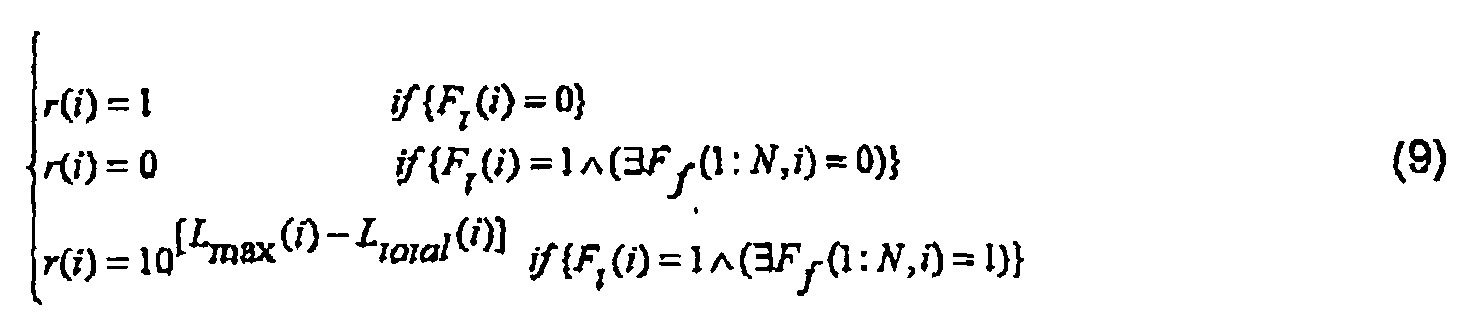
- the gain weighting ratio r(i) is a key parameter for calculating the appropriate gain value for each band. It defines the amount of contribution made by the broadband gain and narrowband gain to the final gain value, based on the time domain and frequency domain shock states.
- the equation (9) represents the conditions used to calculate the gain weighting ratio r(i): where
- the value r(i) is calculated per sample block and it considers the overall frequency domain shock flag to be equal to one when at least one band is in shock.
- the value r(i) is set to one during the normal conditions where no shock is detected (i.e. and and also at the end of a shock (i.e. ) and . This is due to the fact that by setting the gain ratio to one during the normal conditions, only the narrowband gain is enabled and by changing the gain values, the frequency response of the system can be modified. Also, at the end of a shock, because of the "inherited blocks" from the shock period in the analysis window, the frequency bands carry high energy levels while no time domain shock has been detected. This results in an overshoot in the synthesis output if no gain is applied. This effect can be managed by enabling the narrowband gain and using the average energy band levels L avg (j,i) to calculate the gain values.
- the shock is detected only in the time domain (i.e. and ) and as a result only the broadband gain can be used to compress the shock. Therefore for full shock compensation, the gain ratio is set to zero.
- the narrowband gain is brought to the picture automatically, as soon as the band levels reach the threshold values.
- the r(i) is calculated as the ratio of the maximum energy level carried by any of the bands in block over the total energy carried by all the bands in corresponding block, L total (i).
- processing in a plurality of frequency domain bands provides the flexibility needed to effectively protect against wideband (in frequency) and narrowband shock signals.
- band-based gain control and/or adaptive processing provides localized gain control that results in high fidelity because gain adjustments are only made in the frequency ranges where they are necessary.
- Periodic acoustic shock signals can be virtually eliminated using sub-band implementations of Least Mean Squares (LMS) periodic interference cancellation techniques as described in, for example, B. Widrow and S. D. Stearns, "Adaptive signal processing.” Englewood Cliffs, NJ: Prentice-Hall, 1985., which is incorporated herein by reference.
- LMS Least Mean Squares
- These may be implemented at the block 8 of Figure 1 in subband outputs from the WOLA analysis as described below.
- Sub-band adaptive processing disclosed in Canadian Patent Application No. 2,397,080, entitled by “Sub-band Adaptive Signal Processing In An Oversampled Filterbank” and Canadian Patent Application No. 2,437,477, entitled by “Method and System for Processing Subband Signals Using Adaptive Filters", which are incorporated by reference herewith, is applicable to the sub-band processing of the present invention.
- FIG 8 shows an acoustic shock protection system 90 in accordance with another embodiment of the present invention.
- the audio signal contains the desired speech and acoustic shock event that is assumed to be a periodic noise source.
- the acoustic shock protection system 90 employs sub-band adaptive periodic noise cancellation technique and acts as a periodic noise canceller.
- the system 90 of Figure 8 includes the WOLA analysis fifterbank 50, the WOLA synthesis filterbank 52 and a processing block 92.
- the processing block 92 includes a plurality of sub-band periodic noise cancellation blocks 94A-94N, which corresponds to N sub-bands.
- the WOLA analysis filterbank 50 transforms audio input into a plurality of sub-bands. Each sub-band is then passed to the corresponding periodic noise cancellation block.
- the WOLA synthesis filterbank 52 combines the outputs of the processing block 92 into a single signal.
- the system of Figure 2 may further contain the sub-band periodic noise cancellation block of Figure 8 to improve acoustic shock cancellation.
- the system of Figure 2 works quickly to remove the acoustical trauma while the sub-band periodic noise cancellation goes a step further to actually cancel the interference whenever a periodic acoustical shock is present.
- Figure 9 shows one example of the sub-band periodic noise cancellation block 94 of Figure 8.
- the sub-band periodic noise cancellation block 94 includes a delay block 96, an adaptive filter 98 and a summing block 100.
- a sub-band input is delayed at the delay block 96.
- the delayed version of the audio sub-band input is filtered by the adaptive filter 98 and then subtracted from the original sub-band input by the block 100.
- the resulting error signal from the block 100 acts as the sub-band output.
- the sub-band output is also applied to the adaptive filter 98 to update the adaptive filter 98 using the LMS algorithm or other similar techniques.
- the adaptive filter 98 will cancel the periodic noise because it is correlated with a time-delayed version of itself whereas the desired speech will remain because it is not similarly correlated with the delayed input.
- the sub-band output is made equal to the sub-band input to avoid degradation of the signal.
- This periodicity detector may be made by allowing the sub-band filtering block to always operate while observing the variance of the filter coefficients. During regions where the variance is high, above a settable threshold, periodicity would be declared, activating a switch to the filtered output. Conversely, where the variance is low, below a settable threshold which may be different from the previous threshold to implement hysteresis, periodicity would be declared absent and switching the output to use the unfiltered input.
- the periodicity detection is done with fuzzy logic and the output is a weighted sum of the filtered and unfiltered inputs according to the certainty of the periodicity detection.
- the embodiments of the acoustic shock protection system act as an intelligent limiter, which quickly and accurately recognizes acoustic shock conditions and quickly eliminates the acoustic shock conditions. It can provide broadband and narrowband attenuation of the received signal.
- the system may limit the output levels from the headset to a specified maximum that is frequency dependent.
- the system may provide attenuation of sounds that is below the maximum outputs, but are significantly above the current average sound levels.
- the pattern analysis-based approach of the present invention provides high fidelity and low group delay in the processed output signal relative to existing devices.
- an oversampled filterbank e.g. WOLA fitterbank
- WOLA fitterbank provides low-group delay and the ability to make large gain adjustments without adversely impacting signal fidelity or adjacent band signals. These combine to offer a high level of protection and high fidelity.
- calibration and personalization allow the system to be easily adjusted to work with a specific acoustic configuration (e.g. a specific headset or headphone).
- Built-in calibration software allows for simplified calibration in the field.
- Personalization allows some parameters of the invention to be adjusted by the user so that the performance and fidelity suit their specific preferences.
- the embodiments of the present invention provide the ability to log data and download it for later analysis. This can be done over a wired or wireless (radio frequency or other) link.
- the acoustic shock protection system can be connected to an IP network (and to the Internet) or it can use existing RF teohnologies, such as 802.11, Bluetooth or Zigbee.
- An addressing scheme allows the logging and analysis of data from multiple systems so that the invention can be used in an environment where a number of units need to have data logged and analyzed (e.g. a call center).
- the embodiments of the acoustic shock protection system are applicable to telephone systems (both mobile and land), mobile and land-based radio systems, audio protection systems and similar devices, such as headsets or headphones, that protect users from loud sounds. Similar areas of technology include audio limiters and dynamic range compressors.
- the embodiments described above may be implemented by any hardware, software or a combination of hardware and software having the above descnbed functions.
- the software code either in its entirety or a part thereof, may be stored in a computer readable memory.
- a computer data signal representing the software code which may be embedded in a carrier wave may be transmitted via a communication network.
- Such a computer readable memory and a computer data signal are also within the scope of the present invention, as well as the hardware, software and the combination thereof.
Abstract
Description
This identification mechanism/method effectively makes use of various signal parameters to identify acoustic shock events.


Claims (35)
- A method of providing protection against acoustic shock, the method comprising the steps of:performing a pattern analysis on an input signal to identify a parameter space corresponding to a signal space of the input signal;applying a rule-based decision to the parameter space to detect an acoustic shock event; andremoving the acoustic shock event.
- A method as claimed in claim 1 wherein the step of performing a pattern analysis includes the step of:performing a feature extraction from the input signal to identify the parameter space.
- A method as claimed in claim 1 wherein the step of removing the acoustic shock event includes the step of:performing gain control.
- A method as claimed in claim 3 wherein the gain control is performed by a state machine.
- A method as claimed in claim 1 further comprising the step of:performing calibration to keep an output signal provided to a user at a specific level.
- A method as claimed in claim 1 further comprising the step of:implementing on-line data collection of the acoustic shock event from the input signal.
- A method of providing protection against acoustic shock, the method comprising the steps of:performing a weighted overlap-add (WOLA) analysis on an input signal;performing feature extraction on the input signal and performing feature extraction on the band signals provided by the WOLA analysis;detecting an acoustic shock event based on the input signal and band signal feature extractions;performing gain control based on the shock detection and the features extracted from the input signal and band signals;applying a calibrated gain to meet a predetermined safe output level; andperforming a WOLA synthesis on modified band signals to synthesize an output signal where the band signals are by the gain control.
- A method as claimed in claim 7 wherein the step of detecting an acoustic shock event uses a rule-based decision.
- A method as claimed in claim 7 further comprising the step of:delaying the input signal to the WOLA analysis to allow time to obtain fast broadband features to aid in the interpretation of the WOLA analysis results.
- A system for providing protection against acoustic shock, the device comprising:an analysis module for performing a pattern analysis on an input signal to identify a parameter space corresponding to a signal space of the input signal;a detection module for applying a rule-based decision to the parameter space to detect an acoustic shock event; anda removal module for removing the acoustic shock event.
- A system as claimed in claim 10 wherein the analysis module performs a feature extraction from the input signal to identify the parameter space.
- A system as claimed in claim 10 wherein the removal module performs gain control.
- A system as claimed in claim 12 wherein the detection module includes a state machine for performing the gain control.
- A system as claimed in claim 10 further comprising a removable module for logging the acoustic shock events.
- A system as claimed in claim 10 further comprising a calibration module for performing calibration to keep an output signal provided to a user at a specific level.
- A system as claimed in claim 10 further comprising a logging module for implementing on-line data collection of the acoustic shock event from the input signal.
- A system as claimed in claim 10 further comprising a module for performing weighted overlap-add analysis and synthesis to implement processing in sub-bands.
- A system for providing protection against acoustic shock, the device comprising:a weighted overlap add (WOLA) analysis module for transforming an input signal to a band signal;a feature extraction module for performing feature extraction on the input signal and for performing feature extraction on the band signal;a detection module for detecting an acoustic shock event based on the feature extractions;a gain control module for performing gain control based on the shock detection and the features extracted from the input signal and band signals;a calibration module for applying a calibrated gain to meet a predetermined safe level; anda WOLA synthesis module for synthesizing the band signals to provide an output signal.
- A system as claimed in claim 18 wherein the detecting module detects the acoustic shock event using a rule-based decision.
- A system as claimed in claim 18 further comprising a delay module for delaying the input signal to the WOLA analysis to allow time to obtain fast broadband features to aid in the interpretation of the WOLA analysis results.
- A method of providing protection against an acoustic shock, the method comprising the steps of:transforming an input signal into a plurality of oversampled sub-band signals in a frequency domain;adaptively processing the sub-band signals to remove an acoustic shock event; andcombining the processed sub-band signals to generate the output signal.
- A method as claimed in claim 21 wherein the step of processing the sub-band signals includes the step of:processing each sub-band signal to remove a periodic acoustic shock event.
- A method as claimed in claim 22 wherein the step of processing the sub-band signals includes the steps of:delaying the sub-band signal,adaptively filtering the delayed sub-band signal, andadding the sub-band signal and the result of the filtering step.
- A method as claimed in claim 23 further comprising the step of:adjusting the filter.
- A system for providing protection against an acoustic shock, the device comprising:a weighted overlap-add (WOLA) analysis module for transforming an input signal into a plurality of oversampled sub-band signals in a frequency domain;a processing module for adaptively processing the sub-band signals to remove an acoustic shock event; anda WOLA synthesis module for synthesizing the processed sub-band signals to provide an output signal.
- A system as claimed in claim 25 wherein the processing module includes:a plurality of sub-band periodic acoustic shock cancellation modules, each of which processes a corresponding sub-band signal.
- A system as claimed in claim 26 wherein the sub-band periodic acoustic shock cancellation module includes:a delay module for delaying the sub-band signal,an adaptive filter for adaptively filtering the delayed sub-band signal, anda summer for adding the sub-band signal and the output of the filter.
- A system as claimed in claim 27 further comprising a module for adjusting the filter.
- A method as claimed in claim 9, further comprising the step of adjusting the delay time of the delaying step.
- A method as claimed in claim 29, wherein the delay time is reduced to zero so that the inherent group delay of the WOLA analysis is used to provide the required delay
- A system as claimed in claim 20, further comprising means for adjusting the delay time of the delaying module.
- A system as claimed in claim 31, wherein the delay time is reduced to zero so that the inherent group delay of the WOLA analysis is used to provide the required delay.
- A method as claimed in claim 7, where:the step of detecting an acoustic shock event includes the steps of:determining a time domain shock flag based on the feature extraction from the input signal; anddetermining a narrowband shock flag based on the feature extraction from the band signal,the step of performing gain control includes the steps of:calculating a broadband gain based on the feature extraction from the input signal and the time domain shock flag;calculating a narrowband gain based on the feature extraction from the band signal and the narrowband shock flag;calculating a gain weighting ratio based on the time domain shock flag, the narrowband shock flag and the extracted features of the input signal and band signals; andcalculating a gain for the gain control based on the broadband gain, narrowband gain, the weighting ratio and the narrowband shock flag.
- A method as claimed in claim 33, further comprising the step of:staring a broadband counter when the shock is detected in the time domain.
- A method as claims in claim 34, wherein the broadband counter is used for calculating the broadband gain and the narrowband gain.
Priority Applications (2)
| Application Number | Priority Date | Filing Date | Title |
|---|---|---|---|
| DK10011273.9T DK2262280T3 (en) | 2003-03-31 | 2004-03-31 | Acoustic shock protection method and system |
| EP10011273.9A EP2262280B1 (en) | 2003-03-31 | 2004-03-31 | Method and system for acoustic shock protection |
Applications Claiming Priority (2)
| Application Number | Priority Date | Filing Date | Title |
|---|---|---|---|
| CA002424093A CA2424093A1 (en) | 2003-03-31 | 2003-03-31 | Method and device for acoustic shock protection |
| CA2424093 | 2003-03-31 |
Related Child Applications (1)
| Application Number | Title | Priority Date | Filing Date |
|---|---|---|---|
| EP10011273.9A Division-Into EP2262280B1 (en) | 2003-03-31 | 2004-03-31 | Method and system for acoustic shock protection |
Publications (3)
| Publication Number | Publication Date |
|---|---|
| EP1471767A2 true EP1471767A2 (en) | 2004-10-27 |
| EP1471767A3 EP1471767A3 (en) | 2007-05-30 |
| EP1471767B1 EP1471767B1 (en) | 2021-04-28 |
Family
ID=32932274
Family Applications (2)
| Application Number | Title | Priority Date | Filing Date |
|---|---|---|---|
| EP10011273.9A Expired - Lifetime EP2262280B1 (en) | 2003-03-31 | 2004-03-31 | Method and system for acoustic shock protection |
| EP04007864.4A Expired - Lifetime EP1471767B1 (en) | 2003-03-31 | 2004-03-31 | Method and system for acoustic shock protection |
Family Applications Before (1)
| Application Number | Title | Priority Date | Filing Date |
|---|---|---|---|
| EP10011273.9A Expired - Lifetime EP2262280B1 (en) | 2003-03-31 | 2004-03-31 | Method and system for acoustic shock protection |
Country Status (4)
| Country | Link |
|---|---|
| US (2) | US7672462B2 (en) |
| EP (2) | EP2262280B1 (en) |
| CA (1) | CA2424093A1 (en) |
| DK (2) | DK1471767T3 (en) |
Cited By (10)
| Publication number | Priority date | Publication date | Assignee | Title |
|---|---|---|---|---|
| DE102004041199A1 (en) * | 2004-08-25 | 2006-03-09 | Dietmar Ruwisch | Process and facility calculates damping factor for the damping of acoustic signals, multiplies first acoustic signal with damping value to generate output signal |
| WO2007014795A3 (en) * | 2006-06-13 | 2007-03-29 | Phonak Ag | Method and system for acoustic shock detection and application of said method in hearing devices |
| WO2007106384A1 (en) * | 2006-03-10 | 2007-09-20 | Plantronics, Inc. | Music compatible headset amplifier with anti-startle feature |
| US7983425B2 (en) | 2006-06-13 | 2011-07-19 | Phonak Ag | Method and system for acoustic shock detection and application of said method in hearing devices |
| FR2961926A1 (en) * | 2010-06-29 | 2011-12-30 | France Telecom | METHOD AND DEVICE FOR DETECTING ACOUSTIC SHOCKS |
| WO2012066149A1 (en) * | 2010-11-19 | 2012-05-24 | Jacoti Bvba | Personal communication device with hearing support and method for providing the same |
| EP2469708A1 (en) * | 2010-12-21 | 2012-06-27 | Harman Becker Automotive Systems GmbH | Amplifier current consumption control |
| EP2752991A3 (en) * | 2013-01-02 | 2016-07-27 | Samsung Electronics Co., Ltd | Apparatus and method for processing audio signal |
| CN106911993A (en) * | 2015-12-23 | 2017-06-30 | Gn瑞声达A/S | With the hearing devices that acoustic impluse suppresses |
| US11128946B2 (en) | 2017-01-12 | 2021-09-21 | Sonova Ag | Hearing device with acoustic shock control and method for acoustic shock control in a hearing device |
Families Citing this family (22)
| Publication number | Priority date | Publication date | Assignee | Title |
|---|---|---|---|---|
| CN100402708C (en) * | 2005-04-25 | 2008-07-16 | 周玉成 | Real-time control method in metal electrodeposition process based on neuron networks |
| US8165319B2 (en) * | 2005-05-25 | 2012-04-24 | Hearworks Pty Ltd | Method and system for reproducing an audio signal |
| AU2006251864B2 (en) * | 2005-05-25 | 2011-05-26 | Hearworks Pty Limited | A method and system for reproducing an audio signal |
| ATE440455T1 (en) * | 2006-02-01 | 2009-09-15 | Ruwisch Dietmar Dr | METHOD AND DEVICE FOR HEARING PROTECTION FOR TELEPHONE USERS |
| US8750538B2 (en) * | 2006-05-05 | 2014-06-10 | Creative Technology Ltd | Method for enhancing audio signals |
| US8199918B2 (en) * | 2007-01-09 | 2012-06-12 | Sls International, Inc. | Loudspeaker protection circuit |
| US8325934B2 (en) * | 2007-12-07 | 2012-12-04 | Board Of Trustees Of Northern Illinois University | Electronic pillow for abating snoring/environmental noises, hands-free communications, and non-invasive monitoring and recording |
| US9247346B2 (en) | 2007-12-07 | 2016-01-26 | Northern Illinois Research Foundation | Apparatus, system and method for noise cancellation and communication for incubators and related devices |
| WO2010083879A1 (en) | 2009-01-20 | 2010-07-29 | Widex A/S | Hearing aid and a method of detecting and attenuating transients |
| US9253584B2 (en) * | 2009-12-31 | 2016-02-02 | Nokia Technologies Oy | Monitoring and correcting apparatus for mounted transducers and method thereof |
| KR101896387B1 (en) * | 2011-10-24 | 2018-09-10 | 삼성전자주식회사 | Provention apparatas and method for acoustic shock in a mobile terminal |
| WO2013075848A1 (en) * | 2011-11-21 | 2013-05-30 | Jacoti Bvba | System and method for signal level detection |
| JP5963430B2 (en) * | 2011-12-01 | 2016-08-03 | キヤノン株式会社 | Imaging apparatus, audio processing apparatus, and control method thereof |
| US9208773B2 (en) * | 2011-12-23 | 2015-12-08 | Bose Corporation | Headset noise-based pulsed attenuation |
| US9437213B2 (en) * | 2012-03-05 | 2016-09-06 | Malaspina Labs (Barbados) Inc. | Voice signal enhancement |
| US9697847B2 (en) | 2013-03-14 | 2017-07-04 | Semiconductor Components Industries, Llc | Acoustic signal processing system capable of detecting double-talk and method |
| JP6136995B2 (en) * | 2014-03-07 | 2017-05-31 | 株式会社Jvcケンウッド | Noise reduction device |
| US10575103B2 (en) * | 2015-04-10 | 2020-02-25 | Starkey Laboratories, Inc. | Neural network-driven frequency translation |
| US9843875B2 (en) | 2015-09-25 | 2017-12-12 | Starkey Laboratories, Inc. | Binaurally coordinated frequency translation in hearing assistance devices |
| EP3416167B1 (en) | 2017-06-16 | 2020-05-13 | Nxp B.V. | Signal processor for single-channel periodic noise reduction |
| CN111212372B (en) * | 2020-01-09 | 2022-03-11 | 广州视声智能科技有限公司 | Automatic testing and calibrating method and device for audio call products |
| KR20230087161A (en) * | 2021-12-09 | 2023-06-16 | 현대자동차주식회사 | Vehicle Sound Control Device and Method Thereof |
Citations (5)
| Publication number | Priority date | Publication date | Assignee | Title |
|---|---|---|---|---|
| GB2293078A (en) * | 1994-09-09 | 1996-03-13 | Yamaha Corp | Howling remover composed of adjustable equalizers for attenuating complicated noise peaks |
| US5701352A (en) * | 1994-07-14 | 1997-12-23 | Bellsouth Corporation | Tone suppression automatic gain control for a headset |
| EP0841836A2 (en) * | 1996-11-07 | 1998-05-13 | Roberto Delle Curti | Dynamic equalizing/filtering device |
| US6236731B1 (en) * | 1997-04-16 | 2001-05-22 | Dspfactory Ltd. | Filterbank structure and method for filtering and separating an information signal into different bands, particularly for audio signal in hearing aids |
| WO2003003790A1 (en) * | 2001-06-29 | 2003-01-09 | Hearworks Pty Ltd | Digital signal processing system and method for a telephony interface apparatus |
Family Cites Families (10)
| Publication number | Priority date | Publication date | Assignee | Title |
|---|---|---|---|---|
| CA2036078C (en) * | 1990-02-21 | 1994-07-26 | Fumio Amano | Sub-band acoustic echo canceller |
| US5369711A (en) * | 1990-08-31 | 1994-11-29 | Bellsouth Corporation | Automatic gain control for a headset |
| JP3094517B2 (en) * | 1991-06-28 | 2000-10-03 | 日産自動車株式会社 | Active noise control device |
| US5355418A (en) * | 1992-10-07 | 1994-10-11 | Westinghouse Electric Corporation | Frequency selective sound blocking system for hearing protection |
| US5745580A (en) * | 1994-11-04 | 1998-04-28 | Lord Corporation | Reduction of computational burden of adaptively updating control filter(s) in active systems |
| US6240192B1 (en) | 1997-04-16 | 2001-05-29 | Dspfactory Ltd. | Apparatus for and method of filtering in an digital hearing aid, including an application specific integrated circuit and a programmable digital signal processor |
| US6480610B1 (en) * | 1999-09-21 | 2002-11-12 | Sonic Innovations, Inc. | Subband acoustic feedback cancellation in hearing aids |
| US7003467B1 (en) * | 2000-10-06 | 2006-02-21 | Digital Theater Systems, Inc. | Method of decoding two-channel matrix encoded audio to reconstruct multichannel audio |
| CA2397080C (en) | 2001-08-07 | 2007-06-12 | Dspfactory Ltd. | Sub-band adaptive signal processing in an oversampled filterbank |
| CA2437477C (en) | 2002-08-16 | 2008-11-18 | Dspfactory Ltd. | Method and system for processing subband signals using adaptive filters |
-
2003
- 2003-03-31 CA CA002424093A patent/CA2424093A1/en not_active Abandoned
-
2004
- 2004-03-31 EP EP10011273.9A patent/EP2262280B1/en not_active Expired - Lifetime
- 2004-03-31 DK DK04007864.4T patent/DK1471767T3/en active
- 2004-03-31 US US10/815,891 patent/US7672462B2/en active Active
- 2004-03-31 EP EP04007864.4A patent/EP1471767B1/en not_active Expired - Lifetime
- 2004-03-31 DK DK10011273.9T patent/DK2262280T3/en active
-
2010
- 2010-01-13 US US12/686,948 patent/US8379869B2/en not_active Expired - Fee Related
Patent Citations (5)
| Publication number | Priority date | Publication date | Assignee | Title |
|---|---|---|---|---|
| US5701352A (en) * | 1994-07-14 | 1997-12-23 | Bellsouth Corporation | Tone suppression automatic gain control for a headset |
| GB2293078A (en) * | 1994-09-09 | 1996-03-13 | Yamaha Corp | Howling remover composed of adjustable equalizers for attenuating complicated noise peaks |
| EP0841836A2 (en) * | 1996-11-07 | 1998-05-13 | Roberto Delle Curti | Dynamic equalizing/filtering device |
| US6236731B1 (en) * | 1997-04-16 | 2001-05-22 | Dspfactory Ltd. | Filterbank structure and method for filtering and separating an information signal into different bands, particularly for audio signal in hearing aids |
| WO2003003790A1 (en) * | 2001-06-29 | 2003-01-09 | Hearworks Pty Ltd | Digital signal processing system and method for a telephony interface apparatus |
Cited By (22)
| Publication number | Priority date | Publication date | Assignee | Title |
|---|---|---|---|---|
| DE102004041199A1 (en) * | 2004-08-25 | 2006-03-09 | Dietmar Ruwisch | Process and facility calculates damping factor for the damping of acoustic signals, multiplies first acoustic signal with damping value to generate output signal |
| DE102004041199B4 (en) * | 2004-08-25 | 2006-06-29 | Dietmar Ruwisch | Process and facility calculates damping factor for the damping of acoustic signals, multiplies first acoustic signal with damping value to generate output signal |
| WO2007106384A1 (en) * | 2006-03-10 | 2007-09-20 | Plantronics, Inc. | Music compatible headset amplifier with anti-startle feature |
| WO2007014795A3 (en) * | 2006-06-13 | 2007-03-29 | Phonak Ag | Method and system for acoustic shock detection and application of said method in hearing devices |
| US7983425B2 (en) | 2006-06-13 | 2011-07-19 | Phonak Ag | Method and system for acoustic shock detection and application of said method in hearing devices |
| WO2012001261A1 (en) * | 2010-06-29 | 2012-01-05 | France Telecom | Method and device for detecting acoustic shocks |
| FR2961926A1 (en) * | 2010-06-29 | 2011-12-30 | France Telecom | METHOD AND DEVICE FOR DETECTING ACOUSTIC SHOCKS |
| US9031245B2 (en) | 2010-06-29 | 2015-05-12 | France Telecom | Method and device for detecting acoustic shocks |
| WO2012066149A1 (en) * | 2010-11-19 | 2012-05-24 | Jacoti Bvba | Personal communication device with hearing support and method for providing the same |
| US9055377B2 (en) | 2010-11-19 | 2015-06-09 | Jacoti Bvba | Personal communication device with hearing support and method for providing the same |
| US10008993B2 (en) | 2010-12-21 | 2018-06-26 | Harman Becker Automotive Systems Gmbh | Amplifier current consumption control |
| EP2469708A1 (en) * | 2010-12-21 | 2012-06-27 | Harman Becker Automotive Systems GmbH | Amplifier current consumption control |
| CN102545794A (en) * | 2010-12-21 | 2012-07-04 | 哈曼贝克自动系统股份有限公司 | Amplifier current consumption control |
| CN102545794B (en) * | 2010-12-21 | 2014-12-03 | 哈曼贝克自动系统股份有限公司 | Amplifier current consumption control |
| US9350314B2 (en) | 2010-12-21 | 2016-05-24 | Harman Becker Automotive Systems Gmbh | Amplifier current consumption control |
| EP2521377A1 (en) * | 2011-05-06 | 2012-11-07 | Jacoti BVBA | Personal communication device with hearing support and method for providing the same |
| EP2752991A3 (en) * | 2013-01-02 | 2016-07-27 | Samsung Electronics Co., Ltd | Apparatus and method for processing audio signal |
| CN106911993A (en) * | 2015-12-23 | 2017-06-30 | Gn瑞声达A/S | With the hearing devices that acoustic impluse suppresses |
| EP3534625A1 (en) * | 2015-12-23 | 2019-09-04 | GN Hearing A/S | A hearing device with suppression of sound impulses |
| CN106911993B (en) * | 2015-12-23 | 2021-06-08 | Gn瑞声达A/S | Hearing device with sound pulse suppression |
| US11350224B2 (en) | 2015-12-23 | 2022-05-31 | Gn Hearing A/S | Hearing device with suppression of sound impulses |
| US11128946B2 (en) | 2017-01-12 | 2021-09-21 | Sonova Ag | Hearing device with acoustic shock control and method for acoustic shock control in a hearing device |
Also Published As
| Publication number | Publication date |
|---|---|
| EP2262280A3 (en) | 2011-01-12 |
| EP1471767A3 (en) | 2007-05-30 |
| US8379869B2 (en) | 2013-02-19 |
| EP2262280A2 (en) | 2010-12-15 |
| US7672462B2 (en) | 2010-03-02 |
| DK2262280T3 (en) | 2014-01-27 |
| DK1471767T3 (en) | 2021-06-21 |
| EP1471767B1 (en) | 2021-04-28 |
| US20040234079A1 (en) | 2004-11-25 |
| CA2424093A1 (en) | 2004-09-30 |
| EP2262280B1 (en) | 2013-10-23 |
| US20100142714A1 (en) | 2010-06-10 |
Similar Documents
| Publication | Publication Date | Title |
|---|---|---|
| US8379869B2 (en) | Method and system for acoustic shock protection | |
| US7974428B2 (en) | Hearing aid with acoustic feedback suppression | |
| EP1068773B2 (en) | Apparatus and methods for combining audio compression and feedback cancellation in a hearing aid | |
| EP1121834B1 (en) | Hearing aids based on models of cochlear compression | |
| EP3236675B1 (en) | Neural network-driven feedback cancellation | |
| EP3337186A1 (en) | Binaural hearing device system with a binaural impulse environment classifier | |
| EP1111960B1 (en) | Digital hearing device and method | |
| CA2590201C (en) | Hearing aid with feedback model gain estimation | |
| US20050018862A1 (en) | Digital signal processing system and method for a telephony interface apparatus | |
| CA2643716C (en) | Hearing aid with adaptive feedback suppression | |
| US7092532B2 (en) | Adaptive feedback canceller | |
| EP2106163B1 (en) | Apparatus and method for dynamic detection and attenuation of periodic acoustic feedback | |
| WO2001022775A2 (en) | Subband acoustic feedback cancellation in hearing aids | |
| EP2082615A1 (en) | Hearing aid having an occlusion reduction unit, and method for occlusion reduction | |
| WO2007099116A2 (en) | Hearing aid and method of compensation for direct sound in hearing aids | |
| EP3236677A1 (en) | Tonality-driven feedback canceler adaptation | |
| WO2007014795A2 (en) | Method and system for acoustic shock detection and application of said method in hearing devices | |
| EP1829028A1 (en) | Method and apparatus for adaptive sound processing parameters | |
| CA2464171C (en) | Method and system for acoustic shock protection | |
| Choy et al. | Subband-based acoustic shock limiting algorithm on a low-resource DSP system. | |
| CN116782084A (en) | Audio signal processing method and device, earphone and storage medium | |
| CN113421539A (en) | Active noise reduction method and device, electronic equipment and computer readable storage medium | |
| DK1068773T4 (en) | Apparatus and method for combining audio compression and feedback suppression in a hearing aid |
Legal Events
| Date | Code | Title | Description |
|---|---|---|---|
| PUAI | Public reference made under article 153(3) epc to a published international application that has entered the european phase |
Free format text: ORIGINAL CODE: 0009012 |
|
| AK | Designated contracting states |
Kind code of ref document: A2 Designated state(s): AT BE BG CH CY CZ DE DK EE ES FI FR GB GR HU IE IT LI LU MC NL PL PT RO SE SI SK TR |
|
| AX | Request for extension of the european patent |
Extension state: AL LT LV MK |
|
| RAP1 | Party data changed (applicant data changed or rights of an application transferred) |
Owner name: EMMA MIXED SIGNAL C.V. |
|
| PUAL | Search report despatched |
Free format text: ORIGINAL CODE: 0009013 |
|
| AK | Designated contracting states |
Kind code of ref document: A3 Designated state(s): AT BE BG CH CY CZ DE DK EE ES FI FR GB GR HU IE IT LI LU MC NL PL PT RO SE SI SK TR |
|
| AX | Request for extension of the european patent |
Extension state: AL LT LV MK |
|
| RIC1 | Information provided on ipc code assigned before grant |
Ipc: A61F 11/14 20060101ALI20070426BHEP Ipc: H04M 3/00 20060101ALI20070426BHEP Ipc: H03G 11/04 20060101ALI20070426BHEP Ipc: H04R 5/04 20060101AFI20040709BHEP Ipc: H03G 7/06 20060101ALI20070426BHEP Ipc: H03G 3/30 20060101ALI20070426BHEP Ipc: H03G 5/16 20060101ALI20070426BHEP |
|
| 17P | Request for examination filed |
Effective date: 20071121 |
|
| AKX | Designation fees paid |
Designated state(s): AT BE BG CH CY CZ DE DK EE ES FI FR GB GR HU IE IT LI LU MC NL PL PT RO SE SI SK TR |
|
| 17Q | First examination report despatched |
Effective date: 20080205 |
|
| RAP1 | Party data changed (applicant data changed or rights of an application transferred) |
Owner name: SEMICONDUCTOR COMPONENTS INDUSTRIES, LLC |
|
| STAA | Information on the status of an ep patent application or granted ep patent |
Free format text: STATUS: EXAMINATION IS IN PROGRESS |
|
| RAP1 | Party data changed (applicant data changed or rights of an application transferred) |
Owner name: GN HEARING A/S |
|
| RIC1 | Information provided on ipc code assigned before grant |
Ipc: H03G 11/04 20060101ALI20070426BHEP Ipc: H03G 3/30 20060101ALI20070426BHEP Ipc: H03G 7/06 20060101ALI20070426BHEP Ipc: H04M 3/00 20060101ALI20070426BHEP Ipc: H03G 5/16 20060101ALI20070426BHEP Ipc: A61F 11/14 20060101ALI20070426BHEP Ipc: H04R 5/04 20060101AFI20040709BHEP |
|
| RIC1 | Information provided on ipc code assigned before grant |
Ipc: A61F 11/14 20060101ALN20200415BHEP Ipc: H04R 25/00 20060101AFI20200415BHEP Ipc: H04R 3/02 20060101ALI20200415BHEP Ipc: H03G 7/00 20060101ALI20200415BHEP |
|
| GRAP | Despatch of communication of intention to grant a patent |
Free format text: ORIGINAL CODE: EPIDOSNIGR1 |
|
| STAA | Information on the status of an ep patent application or granted ep patent |
Free format text: STATUS: GRANT OF PATENT IS INTENDED |
|
| RIC1 | Information provided on ipc code assigned before grant |
Ipc: H04R 25/00 20060101AFI20200423BHEP Ipc: A61F 11/14 20060101ALN20200423BHEP Ipc: H04R 3/02 20060101ALI20200423BHEP Ipc: H03G 7/00 20060101ALI20200423BHEP |
|
| RIC1 | Information provided on ipc code assigned before grant |
Ipc: H03G 7/00 20060101ALI20200429BHEP Ipc: A61F 11/14 20060101ALN20200429BHEP Ipc: H04R 3/02 20060101ALI20200429BHEP Ipc: H04R 25/00 20060101AFI20200429BHEP |
|
| INTG | Intention to grant announced |
Effective date: 20200527 |
|
| GRAJ | Information related to disapproval of communication of intention to grant by the applicant or resumption of examination proceedings by the epo deleted |
Free format text: ORIGINAL CODE: EPIDOSDIGR1 |
|
| STAA | Information on the status of an ep patent application or granted ep patent |
Free format text: STATUS: EXAMINATION IS IN PROGRESS |
|
| REG | Reference to a national code |
Ref country code: DE Ref legal event code: R079 Ref document number: 602004054959 Country of ref document: DE Free format text: PREVIOUS MAIN CLASS: H04R0005040000 Ipc: H04R0025000000 |
|
| GRAP | Despatch of communication of intention to grant a patent |
Free format text: ORIGINAL CODE: EPIDOSNIGR1 |
|
| STAA | Information on the status of an ep patent application or granted ep patent |
Free format text: STATUS: GRANT OF PATENT IS INTENDED |
|
| INTC | Intention to grant announced (deleted) | ||
| RIC1 | Information provided on ipc code assigned before grant |
Ipc: H04R 3/02 20060101ALI20201013BHEP Ipc: H03G 7/00 20060101ALI20201013BHEP Ipc: A61F 11/14 20060101ALN20201013BHEP Ipc: H04R 25/00 20060101AFI20201013BHEP |
|
| INTG | Intention to grant announced |
Effective date: 20201111 |
|
| GRAS | Grant fee paid |
Free format text: ORIGINAL CODE: EPIDOSNIGR3 |
|
| GRAA | (expected) grant |
Free format text: ORIGINAL CODE: 0009210 |
|
| STAA | Information on the status of an ep patent application or granted ep patent |
Free format text: STATUS: THE PATENT HAS BEEN GRANTED |
|
| REG | Reference to a national code |
Ref country code: DE Ref legal event code: R081 Ref document number: 602004054959 Country of ref document: DE Owner name: GN HEARING A/S, DK Free format text: FORMER OWNER: DSPFACTORY LTD., WATERLOO, ONTARIO, CA |
|
| AK | Designated contracting states |
Kind code of ref document: B1 Designated state(s): AT BE BG CH CY CZ DE DK EE ES FI FR GB GR HU IE IT LI LU MC NL PL PT RO SE SI SK TR |
|
| REG | Reference to a national code |
Ref country code: GB Ref legal event code: FG4D |
|
| REG | Reference to a national code |
Ref country code: CH Ref legal event code: EP |
|
| REG | Reference to a national code |
Ref country code: DE Ref legal event code: R096 Ref document number: 602004054959 Country of ref document: DE |
|
| REG | Reference to a national code |
Ref country code: AT Ref legal event code: REF Ref document number: 1388490 Country of ref document: AT Kind code of ref document: T Effective date: 20210515 |
|
| REG | Reference to a national code |
Ref country code: IE Ref legal event code: FG4D |
|
| REG | Reference to a national code |
Ref country code: DK Ref legal event code: T3 Effective date: 20210617 |
|
| REG | Reference to a national code |
Ref country code: AT Ref legal event code: MK05 Ref document number: 1388490 Country of ref document: AT Kind code of ref document: T Effective date: 20210428 |
|
| PG25 | Lapsed in a contracting state [announced via postgrant information from national office to epo] |
Ref country code: AT Free format text: LAPSE BECAUSE OF FAILURE TO SUBMIT A TRANSLATION OF THE DESCRIPTION OR TO PAY THE FEE WITHIN THE PRESCRIBED TIME-LIMIT Effective date: 20210428 Ref country code: BG Free format text: LAPSE BECAUSE OF FAILURE TO SUBMIT A TRANSLATION OF THE DESCRIPTION OR TO PAY THE FEE WITHIN THE PRESCRIBED TIME-LIMIT Effective date: 20210728 Ref country code: FI Free format text: LAPSE BECAUSE OF FAILURE TO SUBMIT A TRANSLATION OF THE DESCRIPTION OR TO PAY THE FEE WITHIN THE PRESCRIBED TIME-LIMIT Effective date: 20210428 Ref country code: NL Free format text: LAPSE BECAUSE OF FAILURE TO SUBMIT A TRANSLATION OF THE DESCRIPTION OR TO PAY THE FEE WITHIN THE PRESCRIBED TIME-LIMIT Effective date: 20210428 |
|
| PG25 | Lapsed in a contracting state [announced via postgrant information from national office to epo] |
Ref country code: SE Free format text: LAPSE BECAUSE OF FAILURE TO SUBMIT A TRANSLATION OF THE DESCRIPTION OR TO PAY THE FEE WITHIN THE PRESCRIBED TIME-LIMIT Effective date: 20210428 Ref country code: GR Free format text: LAPSE BECAUSE OF FAILURE TO SUBMIT A TRANSLATION OF THE DESCRIPTION OR TO PAY THE FEE WITHIN THE PRESCRIBED TIME-LIMIT Effective date: 20210729 Ref country code: PL Free format text: LAPSE BECAUSE OF FAILURE TO SUBMIT A TRANSLATION OF THE DESCRIPTION OR TO PAY THE FEE WITHIN THE PRESCRIBED TIME-LIMIT Effective date: 20210428 Ref country code: PT Free format text: LAPSE BECAUSE OF FAILURE TO SUBMIT A TRANSLATION OF THE DESCRIPTION OR TO PAY THE FEE WITHIN THE PRESCRIBED TIME-LIMIT Effective date: 20210830 Ref country code: ES Free format text: LAPSE BECAUSE OF FAILURE TO SUBMIT A TRANSLATION OF THE DESCRIPTION OR TO PAY THE FEE WITHIN THE PRESCRIBED TIME-LIMIT Effective date: 20210428 |
|
| REG | Reference to a national code |
Ref country code: NL Ref legal event code: MP Effective date: 20210428 |
|
| PG25 | Lapsed in a contracting state [announced via postgrant information from national office to epo] |
Ref country code: RO Free format text: LAPSE BECAUSE OF FAILURE TO SUBMIT A TRANSLATION OF THE DESCRIPTION OR TO PAY THE FEE WITHIN THE PRESCRIBED TIME-LIMIT Effective date: 20210428 Ref country code: SK Free format text: LAPSE BECAUSE OF FAILURE TO SUBMIT A TRANSLATION OF THE DESCRIPTION OR TO PAY THE FEE WITHIN THE PRESCRIBED TIME-LIMIT Effective date: 20210428 Ref country code: CZ Free format text: LAPSE BECAUSE OF FAILURE TO SUBMIT A TRANSLATION OF THE DESCRIPTION OR TO PAY THE FEE WITHIN THE PRESCRIBED TIME-LIMIT Effective date: 20210428 Ref country code: EE Free format text: LAPSE BECAUSE OF FAILURE TO SUBMIT A TRANSLATION OF THE DESCRIPTION OR TO PAY THE FEE WITHIN THE PRESCRIBED TIME-LIMIT Effective date: 20210428 |
|
| REG | Reference to a national code |
Ref country code: DE Ref legal event code: R097 Ref document number: 602004054959 Country of ref document: DE |
|
| PLBE | No opposition filed within time limit |
Free format text: ORIGINAL CODE: 0009261 |
|
| STAA | Information on the status of an ep patent application or granted ep patent |
Free format text: STATUS: NO OPPOSITION FILED WITHIN TIME LIMIT |
|
| 26N | No opposition filed |
Effective date: 20220131 |
|
| PGFP | Annual fee paid to national office [announced via postgrant information from national office to epo] |
Ref country code: GB Payment date: 20220321 Year of fee payment: 19 Ref country code: DK Payment date: 20220318 Year of fee payment: 19 Ref country code: CH Payment date: 20220310 Year of fee payment: 19 |
|
| PGFP | Annual fee paid to national office [announced via postgrant information from national office to epo] |
Ref country code: FR Payment date: 20220317 Year of fee payment: 19 |
|
| PG25 | Lapsed in a contracting state [announced via postgrant information from national office to epo] |
Ref country code: IT Free format text: LAPSE BECAUSE OF FAILURE TO SUBMIT A TRANSLATION OF THE DESCRIPTION OR TO PAY THE FEE WITHIN THE PRESCRIBED TIME-LIMIT Effective date: 20210428 |
|
| PG25 | Lapsed in a contracting state [announced via postgrant information from national office to epo] |
Ref country code: MC Free format text: LAPSE BECAUSE OF FAILURE TO SUBMIT A TRANSLATION OF THE DESCRIPTION OR TO PAY THE FEE WITHIN THE PRESCRIBED TIME-LIMIT Effective date: 20210428 |
|
| REG | Reference to a national code |
Ref country code: BE Ref legal event code: MM Effective date: 20220331 |
|
| PG25 | Lapsed in a contracting state [announced via postgrant information from national office to epo] |
Ref country code: LU Free format text: LAPSE BECAUSE OF NON-PAYMENT OF DUE FEES Effective date: 20220331 Ref country code: IE Free format text: LAPSE BECAUSE OF NON-PAYMENT OF DUE FEES Effective date: 20220331 |
|
| PG25 | Lapsed in a contracting state [announced via postgrant information from national office to epo] |
Ref country code: BE Free format text: LAPSE BECAUSE OF NON-PAYMENT OF DUE FEES Effective date: 20220331 |
|
| PGFP | Annual fee paid to national office [announced via postgrant information from national office to epo] |
Ref country code: DE Payment date: 20230323 Year of fee payment: 20 |
|
| REG | Reference to a national code |
Ref country code: CH Ref legal event code: PL |
|
| REG | Reference to a national code |
Ref country code: DK Ref legal event code: EBP Effective date: 20230331 |
|
| GBPC | Gb: european patent ceased through non-payment of renewal fee |
Effective date: 20230331 |
|
| PG25 | Lapsed in a contracting state [announced via postgrant information from national office to epo] |
Ref country code: GB Free format text: LAPSE BECAUSE OF NON-PAYMENT OF DUE FEES Effective date: 20230331 |
|
| PG25 | Lapsed in a contracting state [announced via postgrant information from national office to epo] |
Ref country code: LI Free format text: LAPSE BECAUSE OF NON-PAYMENT OF DUE FEES Effective date: 20230331 Ref country code: GB Free format text: LAPSE BECAUSE OF NON-PAYMENT OF DUE FEES Effective date: 20230331 Ref country code: FR Free format text: LAPSE BECAUSE OF NON-PAYMENT OF DUE FEES Effective date: 20230331 Ref country code: CH Free format text: LAPSE BECAUSE OF NON-PAYMENT OF DUE FEES Effective date: 20230331 |
|
| PG25 | Lapsed in a contracting state [announced via postgrant information from national office to epo] |
Ref country code: HU Free format text: LAPSE BECAUSE OF FAILURE TO SUBMIT A TRANSLATION OF THE DESCRIPTION OR TO PAY THE FEE WITHIN THE PRESCRIBED TIME-LIMIT; INVALID AB INITIO Effective date: 20040331 |
|
| REG | Reference to a national code |
Ref country code: DE Ref legal event code: R071 Ref document number: 602004054959 Country of ref document: DE |