EP1471731A2 - Mounting structure for compact camera module - Google Patents

Mounting structure for compact camera module Download PDF

Info

Publication number
EP1471731A2
EP1471731A2 EP04251905A EP04251905A EP1471731A2 EP 1471731 A2 EP1471731 A2 EP 1471731A2 EP 04251905 A EP04251905 A EP 04251905A EP 04251905 A EP04251905 A EP 04251905A EP 1471731 A2 EP1471731 A2 EP 1471731A2
Authority
EP
European Patent Office
Prior art keywords
camera module
compact camera
socket
lower portion
contacting
Prior art date
Legal status (The legal status is an assumption and is not a legal conclusion. Google has not performed a legal analysis and makes no representation as to the accuracy of the status listed.)
Withdrawn
Application number
EP04251905A
Other languages
German (de)
French (fr)
Other versions
EP1471731A3 (en
Inventor
Satoshi c/o Mitsumi Electric Co. Ltd. Ajiki
Kazuhiro c/o Mitsumi Electric Co. Ltd. Yaegashi
Yukihiro c/o Mitsumi Electric Co. Ltd. Furusawa
Hironori Nakajo
Michio Sasaki
Current Assignee (The listed assignees may be inaccurate. Google has not performed a legal analysis and makes no representation or warranty as to the accuracy of the list.)
Toshiba Corp
Mitsumi Electric Co Ltd
Original Assignee
Toshiba Corp
Mitsumi Electric Co Ltd
Priority date (The priority date is an assumption and is not a legal conclusion. Google has not performed a legal analysis and makes no representation as to the accuracy of the date listed.)
Filing date
Publication date
Application filed by Toshiba Corp, Mitsumi Electric Co Ltd filed Critical Toshiba Corp
Priority to EP08168349A priority Critical patent/EP2018045A1/en
Priority to EP08168350A priority patent/EP2018046B1/en
Publication of EP1471731A2 publication Critical patent/EP1471731A2/en
Publication of EP1471731A3 publication Critical patent/EP1471731A3/en
Withdrawn legal-status Critical Current

Links

Images

Classifications

    • HELECTRICITY
    • H04ELECTRIC COMMUNICATION TECHNIQUE
    • H04NPICTORIAL COMMUNICATION, e.g. TELEVISION
    • H04N23/00Cameras or camera modules comprising electronic image sensors; Control thereof
    • H04N23/50Constructional details
    • H04N23/54Mounting of pick-up tubes, electronic image sensors, deviation or focusing coils
    • HELECTRICITY
    • H04ELECTRIC COMMUNICATION TECHNIQUE
    • H04NPICTORIAL COMMUNICATION, e.g. TELEVISION
    • H04N7/00Television systems
    • H04N7/14Systems for two-way working
    • H04N7/141Systems for two-way working between two video terminals, e.g. videophone
    • H04N7/142Constructional details of the terminal equipment, e.g. arrangements of the camera and the display
    • H04N2007/145Handheld terminals

Definitions

  • the present invention relates to a mounting structure for installing a compact camera module into a socket, particularly, a mounting structure for installing a compact camera module equipped in an electronic device such as a cellular phone into a socket, and the compact camera module installed in the socket.
  • a compact camera module is directly attached to a circuit board of an electric device by soldering.
  • the compact camera module is attached to the circuit board by installing the compact camera module into a socket attached to the circuit board by soldering. It is preferable to use a socket because it is easy to exchange and repair the compact camera module.
  • the compact camera module which includes two independent components, an image pickup device and a lens holder, is inserted and fitted into a socket in the following way.
  • Contacting members are formed on the bottom of the socket, and electrode pads are formed on the back side of the image pickup device.
  • the image pickup device is inserted into the socket, and the lens holder is joined with the outer surface of the socket to press the image pickup device to move downward. Thereby, the electrode pads on the back side of the image pickup device come into contact with the contacting members in the socket.
  • Japanese Laid Open Patent Application No. 2001-188155, particularly, FIG. 5b, discloses an invention related to this technique.
  • the electrode pads are in firm contact with the contacting members, and this ensures a good electrical connection between the electrode pads and the contacting members.
  • the contacting between the electrode pads and the contacting members imposes a force on the compact camera module in the direction of moving the compact camera module out. For example, when the compact camera module receives a shock, the image pickup device is apt to be separated from the socket. Therefore, there arises a problem in reliability of the compact camera module.
  • the electrode pads on the outer side surface of the compact camera module, and arrange the contacting members on the inner side surface of the socket, so that the compact camera module is sandwiched by the contacting members when the compact camera module is fitted into the socket.
  • the compact camera module does not receive a force causing separation from the socket.
  • a mounting structure for installing a compact camera module into a socket, the mounting structure comprising an electrode pad formed in a lower portion of the compact camera module that includes a lens and a solid image pickup device; a contacting member having a contacting end and a springy portion disposed in the socket, the electrode pad and the contacting end being in contact when the lower portion of the compact camera module is inserted into the socket; and a depressed portion formed on the lower portion of the compact camera module to accommodate the springy portion of the contacting member so that the lower portion of the compact camera module does not make contact with the springy portion of the contacting member when the lower portion of the compact camera module is inserted into the socket.
  • a mounting structure for installing a compact camera module into a socket, the mounting structure comprising an electrode pad formed in a lower portion of the compact camera module that includes a lens and a solid image pickup device; a contacting member having a contacting end disposed in the socket, the electrode pad and the contacting end being in contact when the lower portion of the compact camera module is inserted into the socket; and an engagement member disposed in the socket to lock the compact camera module when the lower portion of the compact camera module is inserted into the socket so that the compact camera module does not separate from the socket.
  • a mounting structure for installing a compact camera module into a socket, the mounting structure comprising an electrode pad formed in a lower portion of the compact camera module that includes a lens and a solid image pickup device; a contacting member having a contacting end disposed in the socket, the electrode pad and the contacting end being in contact when the lower portion of the compact camera module is inserted into the socket; a recess formed on the lower portion of the compact camera module; and a cutout formed on the socket at a position in correspondence to the recess, the recess facing the cutout when the lower portion of the compact camera module is inserted into the socket.
  • the recess is engagable with a de-installation tool through the cutout when the lower portion of the compact camera module is inserted into the socket
  • a compact camera module set comprising a compact camera module including a lens and a solid image pickup device; and a socket.
  • An electrode pad is formed in a lower portion of the compact camera module; a contacting member having a contacting end and a springy portion is disposed in the socket, the electrode pad and the contacting end being in contact when the lower portion of the compact camera module is inserted into the socket; and a depressed portion is formed on the lower portion of the compact camera module to accommodate the springy portion of the contacting member so that the lower portion of the compact camera module does not make contact with the springy portion of the contacting member when the lower portion of the compact camera module is inserted into the socket.
  • a compact camera module set comprising a compact camera module including a lens and a solid image pickup device; and a socket.
  • An electrode pad is formed in a lower portion of the compact camera module that includes a lens and a solid image pickup device; a contacting member having a contacting end is disposed in the socket, the electrode pad and the contacting end being in contact when the lower portion of the compact camera module is inserted into the socket; and an engagement member is disposed in the socket to lock the compact camera module when the lower portion of the compact camera module is inserted into the socket so that the compact camera module does not separate from the socket.
  • a compact camera module set comprising a compact camera module including a lens and a solid image pickup device; and a socket.
  • An electrode pad is formed in a lower portion of the compact camera module that includes a lens and a solid image pickup device; a contacting member having a contacting end is disposed in the socket, the electrode pad and the contacting end being in contact when the lower portion of the compact camera module is inserted into the socket; a recess is formed on the lower portion of the compact camera module; and a cutout is formed on the socket at a position in correspondence to the recess.
  • the recess faces the cutout when the lower portion of the compact camera module is inserted into the socket, and the recess is engagable with a de-installation tool through the cutout when the lower portion of the compact camera module is inserted into the socket.
  • FIGs. 1A through 1D are perspective views of a compact camera module 10 and a socket 20, showing a mounting mechanism for installing the compact camera module 10 into the socket 20 according to an embodiment of the present invention, where FIG. 1A is a perspective view of the compact camera module 10, FIGs. 1B and 1C are perspective views of portions of the compact camera module 10, and FIG. 1D is a perspective view of the socket 20.
  • a coordinate system is defined as follows.
  • the axis X1-X2 and the axis Y1-Y2 are in a horizontal plane, and the axis Z1-Z2 is in the vertical direction; and the axis X1-X2, the axis Y1-Y2, and the axis Z1-Z2 are perpendicular to each other.
  • the compact camera module 10 includes a solid image pickup unit 40 and a lens unit 50 attached to the solid image pickup unit 40.
  • the socket 20 is mounted on a mounting board 60 by soldering terminal portions 22d of signal contact members 22 and terminal portions 27d of ground contact members 27 in the socket 20 with the pad 61 of the mounting board 60.
  • the structure of the socket 20 is descried in detail below with reference to FIG. 6A through FIG. 6D, and FIG. 7A and FIG. 7B.
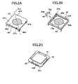
  • FIG. 2A through FIG. 2C are exploded perspective views of the solid image pickup unit 40, where FIG. 2A is a perspective view of the upper side of the cover member 43 in the solid image pickup unit 40, FIG. 2B is a perspective view of the lower side of the cover member 43, and FIG. 2C is a perspective view of the circuit board 42.
  • the solid image pickup unit 40 includes a solid image pickup device 41 (FIG. 2C), a square circuit board 42 (FIG. 2C and FIG. 1C), and a square cover member 43 (FIG. 2A, FIG. 2B, and FIG. 1C).
  • the solid image pickup device 41 for example, is a CCD image pickup device, and is installed on the circuit board 42 as illustrated in FIG. 2C.
  • the cover member 43 for example, is formed from a synthesized resin, and is disposed on the upper side of the circuit board 42 to cover the solid image pickup device 41.
  • a corner 44 of the circuit board 42 is cut along a straight line.
  • a number of half-cut electrode pads 42b are formed on the side surface 42a of the circuit board 42.
  • the half-cut electrode pads 42b are depressed inward and arranged in a row.
  • These half-cut electrode pads 42b are formed by cutting a number of through holes arranged in a substrate in a row. Specifically, the inner surfaces of the through holes formed in a substrate are plated first to form electrodes. Then the substrate is cut along a line through the centers of the through holes, and thereby the half-cut electrode pads 42b are obtained.
  • the cover member 43 includes a square upper lid 43a and a square frame 43b joined to the periphery of the square upper lid 43a.
  • An optical filter 45 is disposed on the upper lid 43a.
  • the portion close to the lower end of the frame 43b is inclined inward, forming a depressed portion 46, which is depressed in the X1 direction, and thereby making the surface 42a, where the half-cut electrode pads 42b are formed, project in the X2 direction.
  • recesses 47a, 47b, 47c, and 47d are formed on the sides of the upper lid 43a.
  • two recesses 48a and 48b are formed at corners of the cover member 43 along a diagonal line.
  • FIG. 3 is a plan view showing the compact camera module 10 installed in the socket 20.
  • the recesses 47a, 47b, 47c, and 47d are formed on the sides of the upper lid 43a.
  • FIG. 4 is a cross-sectional view along the line AA in FIG. 3.
  • the lens unit 50 includes a cylindrical lens holder 53 accommodating a lens 51 and a lens 52 and a cylindrical housing 54. On the inner surface of the housing 54, screws are formed, and the lens holder 53 is screwed into the housing 54 with the screws.
  • FIG. 5 is a cross-sectional view along the diagonal line BB in FIG. 3.
  • the recesses 48a and 48b are formed at corners of the cover member 43 along a diagonal line.
  • FIG. 6A is a plan view of the socket 20.
  • FIG. 6B is a front view of the socket 20.
  • FIG. 6C is a side view of the socket 20.
  • FIG. 6D is a cross-sectional view of the socket 20 along the line DD in FIG. 6A.
  • the socket 20 includes a frame body 21 formed from, for example, a synthesized resin, signal contact members 22 (including portions 22a, 22b, 22c, and 22d as described below) arranged on the inner side surface of the frame body 21, and ground contact members 27 (including portions 27a, 27b, 27c, and 27d as described below) also arranged on the inner side surface of the frame body 21.
  • the frame body 21 has a bottom portion 21b.
  • the frame body 21 is square-shaped, in correspondence to the shape of the solid image pickup unit 40 viewed in the Z1 direction.
  • a corner 21a of the frame body 21 is cut along a straight line to be in correspondence with the corner 44 of the circuit board 42, which is also cut along a straight line.
  • corners of the frame body 21 along the diagonal line DL2 are cut out, forming cutouts 28a and 28b.
  • FIG. 7A and FIG. 7B are cross-sectional views of the compact camera module 10 and the socket 20, showing the operation of the mounting mechanism for installing the compact camera module 10 into the socket 20 to produce a compact camera module set according to the embodiment of the present invention.
  • each of the signal contact members 22 includes a fixed portion 22a fixed to the frame body 21, a springy arm portion 22b connecting with a reversed U-shaped upper end of the fixed portion 22a and extending inward and downward, that is, in the Z2 direction, a contacting portion 22c connecting with the springy arm portion 22b, and a terminal portion 22d extending downward from the lower end of the fixed portion 22a.
  • These signal contact members 22 are arranged at positions in correspondence to the half-cut electrode pads 42b.
  • each of the ground contact members 27 includes a fixed portion 27a fixed to the frame body 21, a springy arm portion 27b connecting with a U-shaped lower end of the fixed portion 27a and extending in the Z1 direction, a hook portion 27c connecting with the springy arm portion 27b and having a bent portion projecting inward, and a terminal portion 27d extending downward from the lower end of the fixed portion 27a.
  • ground contact members 27 are arranged at positions in correspondence to the recesses 47a, 47b, 47c, and 47d.
  • the hook portion 27c is arranged at a position higher than the above contacting portion 22c in the Z1 direction.
  • FIG. 7A the compact camera module 10 is installed in the socket 20, while in FIG. 7B, the compact camera module 10 is uninstalled from the socket 20.
  • the orientation of the compact camera module 10 is aligned with the socket 20. Then, the compact camera module 10 is lowered down from the space above the socket 20, that is, in the Z2 direction, and the solid image pickup unit 40 is inserted into the socket 20. As illustrated in FIG. 7A, the solid image pickup unit 40 is pushed down until the solid image pickup unit 40 is in contact with the bottom 21b.
  • each ground contact member 27 is pushed by the periphery of the circuit board 42, and the springy arm portion 27b is bent and pushed to the side surface of the frame body 21.
  • the contacting portion 22c of each signal contact member 22 is pushed by the periphery of the circuit board 42, and the springy arm portion 22b is bent and pushed to the side surface of the frame body 21.
  • the solid image pickup unit 40 of the compact camera module 10 encounters the hook portion 27c first, and then the contacting portion 22c.
  • the solid image pickup unit 40 of the compact camera module 10 is in contact with the hook portion 27c, static electrical charge generated on the compact camera module 10 discharges through a ground of the mounting board 60.
  • the solid image pickup unit 40 comes in contact with the contacting portion 22c, there is no influence from the static electrical charge.
  • the compact camera module 10 is pushed down successively, until it is set to its final position, as illustrated in FIG. 7B and FIG. 4.
  • the solid image pickup unit 40 of the compact camera module 10 is completely held in the socket 20.
  • the contacting portions 22c of the signal contact members 22 are pushed to fit into the half-cut electrode pads 42b. Because the half-cut electrode pads 42b are depressed relative to the surface 42a of the circuit board 42, comparing with the case in which the half-cut electrode pads 42b are formed on the surface 42a, the springy arm portions 22b of the signal contact members 22 project more to the inner side of the socket 20.
  • the springy arm portions 22b of the signal contact members 22 project into the space provided by the depressed portion 46, and hence, the springy arm portions 22b of the signal contact members 22 do not make contact with the cover member 43 of the solid image pickup unit 40.
  • the springy force of the contacting portions 22c does not decrease, and the contacting portions 22c of the signal contact members 22 are pushed by a sufficiently large force F1 and in firm contact with the half-cut electrode pads 42b. Consequently, the contacting portions 22c are in good electrical contact with the half-cut electrode pads 42b.
  • the four sides of the solid image pickup unit 40 of the compact camera module 10 are pushed by the contacting portions 22c of the signal contact members 22. That is, the signal contact members 22 apply forces to the compact camera module 10 toward the center of the compact camera module 10, but do not apply forces to push out the compact camera module 10.
  • the hook portions 27c of the ground contact members 27 are engaged with the corresponding recesses 47a, 47b, 47c, and 47d, due to a springy force F2 of the springy arm portions 27b of the ground contact members 27.
  • the four sides of the solid image pickup unit 40 of the compact camera module 10 are engaged by the hook portions 27c, thereby preventing unnecessary separation of the compact camera module 10 from the socket 20.
  • the compact camera module 10 fitted in the socket 20 is further installed in a cellular phone, even when static electrical charge is generated on the compact camera module 10 during the use of the cellular phone, the static electrical charge dissipates through the ground of the mounting board 60, and this prevents electrostatic damage to the solid image pickup device 41.
  • the recesses 48a and 48b on the solid image pickup unit 40 of the compact camera module 10 are exposed in the cutouts 28a and 28b of the socket 20. This makes it easy to remove the compact camera module 10 from the socket 20, for example, to repair the compact camera module 10.
  • the hooks 101a and 102a of the arms 101 and 102 are inserted into the recesses 48a and 48b through the cutouts 28a and 28b, and the tool is raised to separate the compact camera module 10 from the socket 20.
  • the recesses 48a and 48b are formed on the solid image pickup unit 40 of the compact camera module 10, and the cutouts 28a and 28b are formed on the socket 20, even though the solid image pickup unit 40 is completely held in the socket 20, by using a simple tool like the tool 100, it is easy to separate the compact camera module 10 from the socket 20.
  • FIG. 8 is a cross-sectional view showing a modification to the mounting mechanism of the present embodiment for installing the compact camera module 10 into the socket 20.
  • the depressed portion 46 may also be formed by a stage-like portion, as the depressed portion 46A shown in FIG. 8.
  • a depressed portion is formed on a compact camera module so that the compact camera module does not make contact with a springy portion of a contacting member when the compact camera module is inserted into a socket, a sufficiently large springy force of the springy portion of the contacting member is maintained, and a contacting end of the contacting member can be reliably brought into contact with an electrode pad on the compact camera module. As a result, it is possible to maintain a good electrical connection between the contacting end and the electrode pad.
  • an engagement member is formed in the socket to lock the compact camera module when the compact camera module is inserted into the socket, even if the compact camera module receives a shock, the compact camera module can hardly depart from the socket.
  • a recess is formed on the compact camera module and a cutout is formed on the socket at positions corresponding to each other, even though the compact camera module is inserted in the socket, because the recess is accessible from the outside through the cutout, a de-installation tool can be used to reach the recess to easily separate the compact camera module from the socket.

Landscapes

  • Engineering & Computer Science (AREA)
  • Multimedia (AREA)
  • Signal Processing (AREA)
  • Studio Devices (AREA)
  • Lens Barrels (AREA)
  • Connecting Device With Holders (AREA)
  • Camera Bodies And Camera Details Or Accessories (AREA)

Abstract

A mounting structure is disclosed that is capable of reliably installing a compact camera module into a socket while maintaining a good electrical connection between them. The mounting structure includes an electrode pad formed in a lower portion of the compact camera module, a contacting member having a contacting end and a springy portion disposed in the socket, and a depressed portion formed on the lower portion of the compact camera module to accommodate the springy portion of the contacting member so that the lower portion of the compact camera module does not make contact with the springy portion of the contacting member when the lower portion of the compact camera module is inserted into the socket. Therefore, the springy portion supplies a sufficiently large springy force to reliably bright the contacting end into contact with the electrode pad, and this maintains a good electrical connection between the contacting end and the electrode pad.

Description

BACKGROUND OF THE INVENTION 1. Field of the Invention
The present invention relates to a mounting structure for installing a compact camera module into a socket, particularly, a mounting structure for installing a compact camera module equipped in an electronic device such as a cellular phone into a socket, and the compact camera module installed in the socket.
2. Description of the Related Art
In the related art, a compact camera module is directly attached to a circuit board of an electric device by soldering. Alternatively, the compact camera module is attached to the circuit board by installing the compact camera module into a socket attached to the circuit board by soldering. It is preferable to use a socket because it is easy to exchange and repair the compact camera module.
In the related art, the compact camera module, which includes two independent components, an image pickup device and a lens holder, is inserted and fitted into a socket in the following way.
Contacting members are formed on the bottom of the socket, and electrode pads are formed on the back side of the image pickup device. The image pickup device is inserted into the socket, and the lens holder is joined with the outer surface of the socket to press the image pickup device to move downward. Thereby, the electrode pads on the back side of the image pickup device come into contact with the contacting members in the socket.
Japanese Laid Open Patent Application No. 2001-188155, particularly, FIG. 5b, discloses an invention related to this technique.
With the above configuration, the electrode pads are in firm contact with the contacting members, and this ensures a good electrical connection between the electrode pads and the contacting members. However, the contacting between the electrode pads and the contacting members imposes a force on the compact camera module in the direction of moving the compact camera module out. For example, when the compact camera module receives a shock, the image pickup device is apt to be separated from the socket. Therefore, there arises a problem in reliability of the compact camera module.
To solve the problem, it is proposed to arrange the electrode pads on the outer side surface of the compact camera module, and arrange the contacting members on the inner side surface of the socket, so that the compact camera module is sandwiched by the contacting members when the compact camera module is fitted into the socket. With such a configuration, the compact camera module does not receive a force causing separation from the socket.
However, considering the case of installing a compact camera module in a cellular phone, because the cellular phone is small in size, it is required to reduce the size of the compact camera module as much as possible. When the socket is made small to satisfy this requirement, the electrical connection between the contacting members and the electrode pads may be degraded. Even when using the former configuration in which the electrode pads are arranged on the back side surface of the compact cameral module and ensure good electrical connection, it is desirable to improve reliability of installing the compact camera module into the socket.
SUMMARY OF THE INVENTION
According to a first aspect of the present invention, there is provided a mounting structure for installing a compact camera module into a socket, the mounting structure comprising an electrode pad formed in a lower portion of the compact camera module that includes a lens and a solid image pickup device; a contacting member having a contacting end and a springy portion disposed in the socket, the electrode pad and the contacting end being in contact when the lower portion of the compact camera module is inserted into the socket; and a depressed portion formed on the lower portion of the compact camera module to accommodate the springy portion of the contacting member so that the lower portion of the compact camera module does not make contact with the springy portion of the contacting member when the lower portion of the compact camera module is inserted into the socket.
According to a second aspect of the present invention, there is provided a mounting structure for installing a compact camera module into a socket, the mounting structure comprising an electrode pad formed in a lower portion of the compact camera module that includes a lens and a solid image pickup device; a contacting member having a contacting end disposed in the socket, the electrode pad and the contacting end being in contact when the lower portion of the compact camera module is inserted into the socket; and an engagement member disposed in the socket to lock the compact camera module when the lower portion of the compact camera module is inserted into the socket so that the compact camera module does not separate from the socket.
According to a third aspect of the present invention, there is provided a mounting structure for installing a compact camera module into a socket, the mounting structure comprising an electrode pad formed in a lower portion of the compact camera module that includes a lens and a solid image pickup device; a contacting member having a contacting end disposed in the socket, the electrode pad and the contacting end being in contact when the lower portion of the compact camera module is inserted into the socket; a recess formed on the lower portion of the compact camera module; and a cutout formed on the socket at a position in correspondence to the recess, the recess facing the cutout when the lower portion of the compact camera module is inserted into the socket. The recess is engagable with a de-installation tool through the cutout when the lower portion of the compact camera module is inserted into the socket
According to a fourth aspect of the present invention, there is provided a compact camera module set, comprising a compact camera module including a lens and a solid image pickup device; and a socket. An electrode pad is formed in a lower portion of the compact camera module; a contacting member having a contacting end and a springy portion is disposed in the socket, the electrode pad and the contacting end being in contact when the lower portion of the compact camera module is inserted into the socket; and a depressed portion is formed on the lower portion of the compact camera module to accommodate the springy portion of the contacting member so that the lower portion of the compact camera module does not make contact with the springy portion of the contacting member when the lower portion of the compact camera module is inserted into the socket.
According to a fifth aspect of the present invention, there is provided a compact camera module set, comprising a compact camera module including a lens and a solid image pickup device; and a socket. An electrode pad is formed in a lower portion of the compact camera module that includes a lens and a solid image pickup device; a contacting member having a contacting end is disposed in the socket, the electrode pad and the contacting end being in contact when the lower portion of the compact camera module is inserted into the socket; and an engagement member is disposed in the socket to lock the compact camera module when the lower portion of the compact camera module is inserted into the socket so that the compact camera module does not separate from the socket.
According to a sixth aspect of the present invention, there is provided a compact camera module set, comprising a compact camera module including a lens and a solid image pickup device; and a socket. An electrode pad is formed in a lower portion of the compact camera module that includes a lens and a solid image pickup device; a contacting member having a contacting end is disposed in the socket, the electrode pad and the contacting end being in contact when the lower portion of the compact camera module is inserted into the socket; a recess is formed on the lower portion of the compact camera module; and a cutout is formed on the socket at a position in correspondence to the recess. The recess faces the cutout when the lower portion of the compact camera module is inserted into the socket, and the recess is engagable with a de-installation tool through the cutout when the lower portion of the compact camera module is inserted into the socket.
These and other objects, features, and advantages of the present invention will become more apparent from the following detailed description of the preferred embodiments given with reference to the accompanying drawings.
BRIEF DESCRIPTION OF THE DRAWINGS
  • FIGs. 1A through 1D are perspective views of a compact camera module 10 and a socket 20, showing a mounting mechanism for installing the compact camera module 10 into the socket 20 according to an embodiment of the present invention;
  • FIG. 2A through FIG. 2C are exploded perspective views of a solid image pickup unit 40, where
  • FIG. 2A is a perspective view of the upper side of a cover member 43 in the solid image pickup unit 40,
  • FIG. 2B is a perspective view of the lower side of the cover member 43, and
  • FIG. 2C is a perspective view of a circuit board 42;
  • FIG. 3 is a plan view showing the compact camera module 10 installed in the socket 20;
  • FIG. 4 is a cross-sectional view along the line AA in FIG. 3, showing the compact camera module 10 installed in the socket 20;
  • FIG. 5 is a cross-sectional view along the line BB in FIG. 3, showing the compact camera module 10 installed in the socket 20;
  • FIG. 6A is a plan view of the socket 20;
  • FIG. 6B is a front view of the socket 20;
  • FIG. 6C is a side view of the socket 20;
  • FIG. 6D is a cross-sectional view of the socket 20 along the line DD in FIG. 6A;
  • FIG. 7A and FIG. 7B are cross-sectional views of the compact camera module 10 and the socket 20, showing the operation of the mounting mechanism for installing the compact camera module 10 into the socket 20 according to the embodiment of the present invention; and
  • FIG. 8 is a cross-sectional view showing a modification of the mounting mechanism of the present embodiment for mounting the compact camera module 10 into the socket 20.
  • DESCRIPTION OF THE EMBODIMENTS
    Below, embodiments of the present invention are explained with reference to the accompanying drawings.
    FIGs. 1A through 1D are perspective views of a compact camera module 10 and a socket 20, showing a mounting mechanism for installing the compact camera module 10 into the socket 20 according to an embodiment of the present invention, where FIG. 1A is a perspective view of the compact camera module 10, FIGs. 1B and 1C are perspective views of portions of the compact camera module 10, and FIG. 1D is a perspective view of the socket 20.
    In FIGs. 1A through 1D and the figures subsequent thereto, a coordinate system is defined as follows. The axis X1-X2 and the axis Y1-Y2 are in a horizontal plane, and the axis Z1-Z2 is in the vertical direction; and the axis X1-X2, the axis Y1-Y2, and the axis Z1-Z2 are perpendicular to each other.
    As illustrated in FIG. 1A, the compact camera module 10 includes a solid image pickup unit 40 and a lens unit 50 attached to the solid image pickup unit 40.
    The components of the mounting mechanism formed on the compact camera module 10 and the socket 20 illustrated in FIG. 1B, FIG. 1C and FIG. 1D are explained below in detail.
    As illustrated in FIG. 1D, the socket 20 is mounted on a mounting board 60 by soldering terminal portions 22d of signal contact members 22 and terminal portions 27d of ground contact members 27 in the socket 20 with the pad 61 of the mounting board 60. The structure of the socket 20 is descried in detail below with reference to FIG. 6A through FIG. 6D, and FIG. 7A and FIG. 7B.
    FIG. 2A through FIG. 2C are exploded perspective views of the solid image pickup unit 40, where FIG. 2A is a perspective view of the upper side of the cover member 43 in the solid image pickup unit 40, FIG. 2B is a perspective view of the lower side of the cover member 43, and FIG. 2C is a perspective view of the circuit board 42.
    As illustrated in FIG. 2A through 2C, the solid image pickup unit 40 includes a solid image pickup device 41 (FIG. 2C), a square circuit board 42 (FIG. 2C and FIG. 1C), and a square cover member 43 (FIG. 2A, FIG. 2B, and FIG. 1C).
    The solid image pickup device 41, for example, is a CCD image pickup device, and is installed on the circuit board 42 as illustrated in FIG. 2C.
    The cover member 43, for example, is formed from a synthesized resin, and is disposed on the upper side of the circuit board 42 to cover the solid image pickup device 41.
    As illustrated in FIG. 2C, a corner 44 of the circuit board 42 is cut along a straight line. On the side surface 42a of the circuit board 42, a number of half-cut electrode pads 42b are formed. The half-cut electrode pads 42b are depressed inward and arranged in a row. These half-cut electrode pads 42b are formed by cutting a number of through holes arranged in a substrate in a row. Specifically, the inner surfaces of the through holes formed in a substrate are plated first to form electrodes. Then the substrate is cut along a line through the centers of the through holes, and thereby the half-cut electrode pads 42b are obtained.
    As illustrated in FIG. 2A and FIG. 2B, as well as the enlarged view in FIG. 2B, the cover member 43 includes a square upper lid 43a and a square frame 43b joined to the periphery of the square upper lid 43a. An optical filter 45 is disposed on the upper lid 43a.
    As illustrated in FIG. 2B, and also referring to FIG. 1B, on the outer side surface of the square frame 43b, the portion close to the lower end of the frame 43b is inclined inward, forming a depressed portion 46, which is depressed in the X1 direction, and thereby making the surface 42a, where the half-cut electrode pads 42b are formed, project in the X2 direction.
    As illustrated in FIG. 2A and FIG. 2B, on the sides of the upper lid 43a, recesses 47a, 47b, 47c, and 47d are formed. In addition, at corners of the cover member 43 along a diagonal line, two recesses 48a and 48b are formed.
    FIG. 3 is a plan view showing the compact camera module 10 installed in the socket 20.
    As illustrated in FIG. 3, the recesses 47a, 47b, 47c, and 47d are formed on the sides of the upper lid 43a.
    FIG. 4 is a cross-sectional view along the line AA in FIG. 3.
    As illustrated in FIG. 4, the lens unit 50 includes a cylindrical lens holder 53 accommodating a lens 51 and a lens 52 and a cylindrical housing 54. On the inner surface of the housing 54, screws are formed, and the lens holder 53 is screwed into the housing 54 with the screws.
    FIG. 5 is a cross-sectional view along the diagonal line BB in FIG. 3.
    As illustrated in FIG. 5, the recesses 48a and 48b are formed at corners of the cover member 43 along a diagonal line.
    FIG. 6A is a plan view of the socket 20.
    FIG. 6B is a front view of the socket 20.
    FIG. 6C is a side view of the socket 20.
    FIG. 6D is a cross-sectional view of the socket 20 along the line DD in FIG. 6A.
    As illustrated in FIG. 6A through 6D, and also referring to FIG. 1D, the socket 20 includes a frame body 21 formed from, for example, a synthesized resin, signal contact members 22 (including portions 22a, 22b, 22c, and 22d as described below) arranged on the inner side surface of the frame body 21, and ground contact members 27 (including portions 27a, 27b, 27c, and 27d as described below) also arranged on the inner side surface of the frame body 21. The frame body 21 has a bottom portion 21b.
    The frame body 21 is square-shaped, in correspondence to the shape of the solid image pickup unit 40 viewed in the Z1 direction. In particular, a corner 21a of the frame body 21 is cut along a straight line to be in correspondence with the corner 44 of the circuit board 42, which is also cut along a straight line. In addition, corners of the frame body 21 along the diagonal line DL2 (FIG. 1D) are cut out, forming cutouts 28a and 28b.
    FIG. 7A and FIG. 7B are cross-sectional views of the compact camera module 10 and the socket 20, showing the operation of the mounting mechanism for installing the compact camera module 10 into the socket 20 to produce a compact camera module set according to the embodiment of the present invention.
    As illustrated in FIG. 7A and FIG. 7B, (make reference to FIG. 6A through FIG. 6D when necessary), each of the signal contact members 22 includes a fixed portion 22a fixed to the frame body 21, a springy arm portion 22b connecting with a reversed U-shaped upper end of the fixed portion 22a and extending inward and downward, that is, in the Z2 direction, a contacting portion 22c connecting with the springy arm portion 22b, and a terminal portion 22d extending downward from the lower end of the fixed portion 22a.
    These signal contact members 22 are arranged at positions in correspondence to the half-cut electrode pads 42b.
    As illustrated in FIG. 7A and FIG. 7B, (make reference to FIG. 6A through FIG. 6D when necessary), each of the ground contact members 27 includes a fixed portion 27a fixed to the frame body 21, a springy arm portion 27b connecting with a U-shaped lower end of the fixed portion 27a and extending in the Z1 direction, a hook portion 27c connecting with the springy arm portion 27b and having a bent portion projecting inward, and a terminal portion 27d extending downward from the lower end of the fixed portion 27a.
    These ground contact members 27 are arranged at positions in correspondence to the recesses 47a, 47b, 47c, and 47d. The hook portion 27c is arranged at a position higher than the above contacting portion 22c in the Z1 direction.
    Below, with reference to FIG. 7A and FIG. 7B, an explanation is made of the operation of installing the compact camera module 10 into the socket 20.
    In FIG. 7A, the compact camera module 10 is installed in the socket 20, while in FIG. 7B, the compact camera module 10 is uninstalled from the socket 20.
    To install the compact camera module 10 into the socket 20, first the orientation of the compact camera module 10 is aligned with the socket 20. Then, the compact camera module 10 is lowered down from the space above the socket 20, that is, in the Z2 direction, and the solid image pickup unit 40 is inserted into the socket 20. As illustrated in FIG. 7A, the solid image pickup unit 40 is pushed down until the solid image pickup unit 40 is in contact with the bottom 21b.
    When fitting the solid image pickup unit 40 of the compact camera module 10 into the socket 20, the hook portion 27c of each ground contact member 27 is pushed by the periphery of the circuit board 42, and the springy arm portion 27b is bent and pushed to the side surface of the frame body 21. Similarly, the contacting portion 22c of each signal contact member 22 is pushed by the periphery of the circuit board 42, and the springy arm portion 22b is bent and pushed to the side surface of the frame body 21.
    Because of the relative positions of the hook portion 27c and the contacting portion 22c in the socket 20, the solid image pickup unit 40 of the compact camera module 10 encounters the hook portion 27c first, and then the contacting portion 22c. When the solid image pickup unit 40 of the compact camera module 10 is in contact with the hook portion 27c, static electrical charge generated on the compact camera module 10 discharges through a ground of the mounting board 60. Thus, when the solid image pickup unit 40 comes in contact with the contacting portion 22c, there is no influence from the static electrical charge.
    The compact camera module 10 is pushed down successively, until it is set to its final position, as illustrated in FIG. 7B and FIG. 4. In FIG. 4, the solid image pickup unit 40 of the compact camera module 10 is completely held in the socket 20.
    The contacting portions 22c of the signal contact members 22 are pushed to fit into the half-cut electrode pads 42b. Because the half-cut electrode pads 42b are depressed relative to the surface 42a of the circuit board 42, comparing with the case in which the half-cut electrode pads 42b are formed on the surface 42a, the springy arm portions 22b of the signal contact members 22 project more to the inner side of the socket 20.
    However, as described above, because the depressed portion 46 is formed on the cover member 43 of the solid image pickup unit 40, there is a space formed between the springy arm portions 22b and the solid image pickup unit 40. Therefore, the springy arm portions 22b of the signal contact members 22 project into the space provided by the depressed portion 46, and hence, the springy arm portions 22b of the signal contact members 22 do not make contact with the cover member 43 of the solid image pickup unit 40. For this reason, the springy force of the contacting portions 22c does not decrease, and the contacting portions 22c of the signal contact members 22 are pushed by a sufficiently large force F1 and in firm contact with the half-cut electrode pads 42b. Consequently, the contacting portions 22c are in good electrical contact with the half-cut electrode pads 42b.
    The four sides of the solid image pickup unit 40 of the compact camera module 10 are pushed by the contacting portions 22c of the signal contact members 22. That is, the signal contact members 22 apply forces to the compact camera module 10 toward the center of the compact camera module 10, but do not apply forces to push out the compact camera module 10.
    As illustrated in FIG. 7B (also referring to FIG. FIG. 3 and FIG. 4), the hook portions 27c of the ground contact members 27 are engaged with the corresponding recesses 47a, 47b, 47c, and 47d, due to a springy force F2 of the springy arm portions 27b of the ground contact members 27. Thereby, the four sides of the solid image pickup unit 40 of the compact camera module 10 are engaged by the hook portions 27c, thereby preventing unnecessary separation of the compact camera module 10 from the socket 20.
    When the compact camera module 10 fitted in the socket 20 is further installed in a cellular phone, even when static electrical charge is generated on the compact camera module 10 during the use of the cellular phone, the static electrical charge dissipates through the ground of the mounting board 60, and this prevents electrostatic damage to the solid image pickup device 41.
    Further, as illustrated in FIG. 5, the recesses 48a and 48b on the solid image pickup unit 40 of the compact camera module 10 are exposed in the cutouts 28a and 28b of the socket 20. This makes it easy to remove the compact camera module 10 from the socket 20, for example, to repair the compact camera module 10.
    Specifically, as illustrated in FIG. 5, using a tool having two arms 101 and 102, the hooks 101a and 102a of the arms 101 and 102 are inserted into the recesses 48a and 48b through the cutouts 28a and 28b, and the tool is raised to separate the compact camera module 10 from the socket 20.
    Because the recesses 48a and 48b are formed on the solid image pickup unit 40 of the compact camera module 10, and the cutouts 28a and 28b are formed on the socket 20, even though the solid image pickup unit 40 is completely held in the socket 20, by using a simple tool like the tool 100, it is easy to separate the compact camera module 10 from the socket 20.
    FIG. 8 is a cross-sectional view showing a modification to the mounting mechanism of the present embodiment for installing the compact camera module 10 into the socket 20.
    As illustrated in FIG. 8, instead of the inclined portion, the depressed portion 46 may also be formed by a stage-like portion, as the depressed portion 46A shown in FIG. 8.
    In addition, instead of fixing the compact camera module 10 by the hook portions 27c of the ground contact members 27, a configuration may be adopted in which the socket 20 is fixed by hook portions formed on the compact camera module 10.
    While the present invention has been described with reference to specific embodiments chosen for purpose of illustration, it should be apparent that the invention is not limited to these embodiments, but numerous modifications could be made thereto by those skilled in the art without departing from the basic concept and scope of the invention.
    Summarizing the effect of the invention, because a depressed portion is formed on a compact camera module so that the compact camera module does not make contact with a springy portion of a contacting member when the compact camera module is inserted into a socket, a sufficiently large springy force of the springy portion of the contacting member is maintained, and a contacting end of the contacting member can be reliably brought into contact with an electrode pad on the compact camera module. As a result, it is possible to maintain a good electrical connection between the contacting end and the electrode pad.
    In addition, because an engagement member is formed in the socket to lock the compact camera module when the compact camera module is inserted into the socket, even if the compact camera module receives a shock, the compact camera module can hardly depart from the socket.
    In addition, because a grounding contacting member is provided, even if static electrical charge is generated on the compact camera module, it discharges through the grounding contacting member, and thus the compact camera module does not retain the charge, thereby, preventing electrostatic damage to the compact camera module.
    In addition, a recess is formed on the compact camera module and a cutout is formed on the socket at positions corresponding to each other, even though the compact camera module is inserted in the socket, because the recess is accessible from the outside through the cutout, a de-installation tool can be used to reach the recess to easily separate the compact camera module from the socket.
    This patent application is based on Japanese Priority Patent Application No. 2003-096347 filed on March 31, 2003, the entire contents of which are hereby incorporated by reference.

    Claims (8)

    1. A mounting structure for installing a compact camera module into a socket, the mounting structure comprising:
      an electrode pad formed in a lower portion of the compact camera module that includes a lens and a solid image pickup device;
      a contacting member having a contacting end and a springy portion disposed in the socket, the electrode pad and the contacting end being in contact when the lower portion of the compact camera module is inserted into the socket; and
      a depressed portion formed on the lower portion of the compact camera module to accommodate the springy portion of the contacting member so that the lower portion of the compact camera module does not make contact with the springy portion of the contacting member when the lower portion of the compact camera module is inserted into the socket.
    2. A mounting structure for installing a compact camera module into a socket, the mounting structure comprising:
      an electrode pad formed in a lower portion of the compact camera module that includes a lens and a solid image pickup device;
      a contacting member having a contacting end disposed in the socket, the electrode pad and the contacting end being in contact when the lower portion of the compact camera module is inserted into the socket; and
      an engagement member disposed in the socket to lock the compact camera module when the lower portion of the compact camera module is inserted into the socket so that the compact camera module does not separate from the socket.
    3. The mounting structure as claimed in claim 2, wherein
         the socket comprises a grounding contacting member; and
         the engagement member is a portion of the grounding contacting member.
    4. A mounting structure for installing a compact camera module into a socket, the mounting structure comprising:
      an electrode pad formed in a lower portion of the compact camera module that includes a lens and a solid image pickup device;
      a contacting member having a contacting end disposed in the socket, the electrode pad and the contacting end being in contact when the lower portion of the compact camera module is inserted into the socket;
      a recess formed on the lower portion of the compact camera module; and
      a cutout formed on the socket at a position in correspondence to the recess, the recess facing the cutout when the lower portion of the compact camera module is inserted into the socket,
         wherein
         the recess is engagable with a de-installation tool through the cutout when the lower portion of the compact camera module is inserted into the socket.
    5. A compact camera module set, comprising:
      a compact camera module including a lens and a solid image pickup device; and
      a socket,
         wherein
         an electrode pad is formed in a lower portion of the compact camera module;
         a contacting member having a contacting end and a springy portion is disposed in the socket, the electrode pad and the contacting end being in contact when the lower portion of the compact camera module is inserted into the socket; and
         a depressed portion is formed on the lower portion of the compact camera module to accommodate the springy portion of the contacting member so that the lower portion of the compact camera module does not make contact with the springy portion of the contacting member when the lower portion of the compact camera module is inserted into the socket.
    6. A compact camera module set, comprising:
      a compact camera module including a lens and a solid image pickup device; and
      a socket,
         wherein
         an electrode pad is formed in a lower portion of the compact camera module that includes a lens and a solid image pickup device;
         a contacting member having a contacting end is disposed in the socket, the electrode pad and the contacting end being in contact when the lower portion of the compact camera module is inserted into the socket; and
         an engagement member is disposed in the socket to lock the compact camera module when the lower portion of the compact camera module is inserted into the socket so that the compact camera module does not separate from the socket.
    7. The compact camera module set as claimed in claim 6, wherein
         the socket comprises a grounding contacting member; and
         the engagement member is a portion of the grounding contacting member.
    8. A compact camera module set, comprising:
      a compact camera module including a lens and a solid image pickup device; and
      a socket,
         wherein
         an electrode pad is formed in a lower portion of the compact camera module that includes a lens and a solid image pickup device;
         a contacting member having a contacting end is disposed in the socket, the electrode pad and the contacting end being in contact when the lower portion of the compact camera module is inserted into the socket;
         a recess is formed on the lower portion of the compact camera module; and
         a cutout is formed on the socket at a position in correspondence to the recess, the recess facing the cutout when the lower portion of the compact camera module is inserted into the socket, the recess being engagable with a de-installation tool through the cutout when the lower portion of the compact camera module is inserted into the socket.
    EP04251905A 2003-03-31 2004-03-30 Mounting structure for compact camera module Withdrawn EP1471731A3 (en)

    Priority Applications (2)

    Application Number Priority Date Filing Date Title
    EP08168349A EP2018045A1 (en) 2003-03-31 2004-03-30 Mounting Structure For Compact Camera Module
    EP08168350A EP2018046B1 (en) 2003-03-31 2004-03-30 Mounting Structure For Compact Camera Module

    Applications Claiming Priority (2)

    Application Number Priority Date Filing Date Title
    JP2003096347 2003-03-31
    JP2003096347A JP2004304604A (en) 2003-03-31 2003-03-31 Mounting structure of small camera module to socket

    Related Child Applications (2)

    Application Number Title Priority Date Filing Date
    EP08168350A Division EP2018046B1 (en) 2003-03-31 2004-03-30 Mounting Structure For Compact Camera Module
    EP08168349A Division EP2018045A1 (en) 2003-03-31 2004-03-30 Mounting Structure For Compact Camera Module

    Publications (2)

    Publication Number Publication Date
    EP1471731A2 true EP1471731A2 (en) 2004-10-27
    EP1471731A3 EP1471731A3 (en) 2007-10-17

    Family

    ID=32959546

    Family Applications (3)

    Application Number Title Priority Date Filing Date
    EP04251905A Withdrawn EP1471731A3 (en) 2003-03-31 2004-03-30 Mounting structure for compact camera module
    EP08168350A Expired - Lifetime EP2018046B1 (en) 2003-03-31 2004-03-30 Mounting Structure For Compact Camera Module
    EP08168349A Withdrawn EP2018045A1 (en) 2003-03-31 2004-03-30 Mounting Structure For Compact Camera Module

    Family Applications After (2)

    Application Number Title Priority Date Filing Date
    EP08168350A Expired - Lifetime EP2018046B1 (en) 2003-03-31 2004-03-30 Mounting Structure For Compact Camera Module
    EP08168349A Withdrawn EP2018045A1 (en) 2003-03-31 2004-03-30 Mounting Structure For Compact Camera Module

    Country Status (5)

    Country Link
    US (1) US20040247311A1 (en)
    EP (3) EP1471731A3 (en)
    JP (1) JP2004304604A (en)
    CN (3) CN100576887C (en)
    DE (1) DE602004026129D1 (en)

    Cited By (4)

    * Cited by examiner, † Cited by third party
    Publication number Priority date Publication date Assignee Title
    WO2006042133A1 (en) * 2004-10-07 2006-04-20 Molex Incorporated Socket for digital camera module
    EP2234465A1 (en) * 2009-03-26 2010-09-29 Samsung Electronics Co., Ltd. Structure for fixing camera module on biodrive
    EP2863624A3 (en) * 2013-10-16 2015-08-05 Samsung Electro-Mechanics Co., Ltd. Camera module, method for aligning optical axis of camera module and portable electronic device including camera module
    EP2572240A4 (en) * 2010-05-20 2015-10-07 Lg Innotek Co Ltd CAMERA MODULE HAVING A MEMS ACTUATOR, CONNECTING METHOD FOR A SHUTTER COIL OF A CAMERA MODULE, AND CAMERA MODULE MADE THEREBY USING THE SAME

    Families Citing this family (25)

    * Cited by examiner, † Cited by third party
    Publication number Priority date Publication date Assignee Title
    JP4562538B2 (en) * 2005-01-31 2010-10-13 モレックス インコーポレイテド Module socket
    TWM271287U (en) * 2005-02-18 2005-07-21 Molex Taiwan Ltd Camera module connector
    US20060189216A1 (en) * 2005-02-18 2006-08-24 Ming-Hsun Yang Camera module connector keying structure
    JP2006237756A (en) * 2005-02-22 2006-09-07 Seiko Precision Inc Solid-state imaging apparatus and electronic apparatus provided with the same
    JP2006236936A (en) * 2005-02-28 2006-09-07 Mitsumi Electric Co Ltd Connector locking device for modules
    JP4632083B2 (en) * 2005-03-31 2011-02-16 ミツミ電機株式会社 The camera module
    KR100658150B1 (en) 2005-04-08 2006-12-15 삼성전기주식회사 Camera module and its manufacturing method
    CN100399637C (en) * 2005-05-16 2008-07-02 富士康(昆山)电脑接插件有限公司 electrical connector
    WO2007007641A1 (en) * 2005-07-08 2007-01-18 Fci Connectors Singapore Pte Ltd. Method of manufacturing contact having latch mechanism
    JP4711797B2 (en) * 2005-09-30 2011-06-29 モレックス インコーポレイテド Module socket
    JP2007123214A (en) * 2005-10-31 2007-05-17 Mitsumi Electric Co Ltd Camera module mounting structure
    CN100502165C (en) * 2005-12-02 2009-06-17 鸿富锦精密工业(深圳)有限公司 Fixture of digital code camera module group
    JP4359591B2 (en) * 2005-12-26 2009-11-04 アルプス電気株式会社 The camera module
    TWM304793U (en) * 2006-04-03 2007-01-11 Hon Hai Prec Ind Co Ltd Electrical connector assembly
    KR100735317B1 (en) 2006-04-20 2007-07-04 삼성전기주식회사 Small Camera Module Package
    KR101231305B1 (en) * 2006-05-25 2013-02-07 엘지이노텍 주식회사 camera module assembly
    CN200941518Y (en) * 2006-08-01 2007-08-29 富士康(昆山)电脑接插件有限公司 electrical connector
    TWM310502U (en) * 2006-11-17 2007-04-21 Molex Taiwan Ltd Electrical connection device
    JP4840114B2 (en) * 2006-12-11 2011-12-21 パナソニック株式会社 Camera module and manufacturing method thereof
    CN101373248A (en) * 2007-08-24 2009-02-25 鸿富锦精密工业(深圳)有限公司 Lens mount and its applied lens components
    CN104469099A (en) * 2013-09-25 2015-03-25 深圳富泰宏精密工业有限公司 Camera installation structure and portable electronic device comprising same
    WO2019201167A1 (en) * 2018-04-17 2019-10-24 宁波舜宇光电信息有限公司 Photographing module having chamfer, light-sensing assembly, manufacturing method, and electronic device
    CN110392187B (en) * 2018-04-17 2023-01-13 宁波舜宇光电信息有限公司 Camera module with chamfer, photosensitive assembly, preparation method and electronic equipment
    US11831969B1 (en) 2021-01-29 2023-11-28 Apple Inc. Asymmetric component arrangement within small form factor cameras
    DE102022202777B3 (en) * 2022-03-22 2023-06-07 Robert Bosch Gesellschaft mit beschränkter Haftung Method of manufacturing a camera device and camera device for a vehicle

    Family Cites Families (16)

    * Cited by examiner, † Cited by third party
    Publication number Priority date Publication date Assignee Title
    US4052118A (en) * 1975-05-30 1977-10-04 Amp Incorporated Contact carrying spring member
    US4089575A (en) * 1976-09-27 1978-05-16 Amp Incorporated Connector for connecting a circuit element to the surface of a substrate
    JPS59132152A (en) * 1983-01-18 1984-07-30 Japan Aviation Electronics Ind Ltd Self-locking contact
    DE3421672A1 (en) * 1984-06-09 1985-12-12 SEMIKRON Gesellschaft für Gleichrichterbau u. Elektronik mbH, 8500 Nürnberg INTERCHANGEABLE RESISTANT, SWITCHABLE SEMICONDUCTOR COMPONENT
    US4755146A (en) * 1987-06-04 1988-07-05 Molex Incorporated Heat-dissipating socket connector for leaded modules
    JP2001188155A (en) * 1999-12-28 2001-07-10 Kuurii Components Kk Image sensor fixing means
    JP2002093539A (en) * 2000-09-13 2002-03-29 D D K Ltd Connector
    JP2002134184A (en) * 2000-10-25 2002-05-10 Yazaki Corp Auxiliary equipment module
    TW528889B (en) * 2000-11-14 2003-04-21 Toshiba Corp Image pickup apparatus, manufacturing method thereof, and portable electric apparatus
    JP2002314856A (en) * 2001-04-17 2002-10-25 Seiko Precision Inc Camera for portable equipment
    JP2003060948A (en) * 2001-06-05 2003-02-28 Seiko Precision Inc Solid-state photographing apparatus
    JP3847108B2 (en) * 2001-06-15 2006-11-15 セイコープレシジョン株式会社 Camera for mobile devices
    JP3620833B2 (en) * 2001-09-18 2005-02-16 Smk株式会社 Module connector
    JP4407090B2 (en) 2001-09-20 2010-02-03 ブラザー工業株式会社 Water-based ink for inkjet recording
    CN2539974Y (en) * 2002-04-22 2003-03-12 庄海 Endoscopic camera lens assembly
    JP2004063425A (en) * 2002-07-31 2004-02-26 Mitsumi Electric Co Ltd Module connector

    Cited By (7)

    * Cited by examiner, † Cited by third party
    Publication number Priority date Publication date Assignee Title
    WO2006042133A1 (en) * 2004-10-07 2006-04-20 Molex Incorporated Socket for digital camera module
    EP2234465A1 (en) * 2009-03-26 2010-09-29 Samsung Electronics Co., Ltd. Structure for fixing camera module on biodrive
    US8531594B2 (en) 2009-03-26 2013-09-10 Samsung Electronics Co., Ltd. Structure for fixing camera module on biodrive
    EP2572240A4 (en) * 2010-05-20 2015-10-07 Lg Innotek Co Ltd CAMERA MODULE HAVING A MEMS ACTUATOR, CONNECTING METHOD FOR A SHUTTER COIL OF A CAMERA MODULE, AND CAMERA MODULE MADE THEREBY USING THE SAME
    US9635232B2 (en) 2010-05-20 2017-04-25 Lg Innotek Co., Ltd. Camera module having MEMS actuator, connecting method for shutter coil of camera module and camera module manufactured by the same method
    EP2863624A3 (en) * 2013-10-16 2015-08-05 Samsung Electro-Mechanics Co., Ltd. Camera module, method for aligning optical axis of camera module and portable electronic device including camera module
    US10194062B2 (en) 2013-10-16 2019-01-29 Samsung Electro-Mechanics Co., Ltd. Camera module, method for aligning optical axis of camera module and portable electronic device including camera module

    Also Published As

    Publication number Publication date
    EP2018045A1 (en) 2009-01-21
    JP2004304604A (en) 2004-10-28
    CN101635794B (en) 2011-01-05
    CN101635795A (en) 2010-01-27
    EP1471731A3 (en) 2007-10-17
    CN101635794A (en) 2010-01-27
    EP2018046B1 (en) 2010-03-17
    CN101635795B (en) 2011-01-05
    EP2018046A1 (en) 2009-01-21
    US20040247311A1 (en) 2004-12-09
    DE602004026129D1 (en) 2010-04-29
    CN100576887C (en) 2009-12-30
    CN1534995A (en) 2004-10-06

    Similar Documents

    Publication Publication Date Title
    EP2018046B1 (en) Mounting Structure For Compact Camera Module
    CN100531314C (en) Image pickup device
    EP1465411B1 (en) Compact camera module
    CN101728744B (en) Module connector
    US20080252777A1 (en) Camera incorporating method and mobile electronic equipment with camera
    US7893989B2 (en) Camera unit for driving lenses and method of manufacturing the same
    JP2006210205A (en) Socket for module
    JP3915733B2 (en) Camera module mounting structure
    CN101442061A (en) Circuit board and camera component using the same
    JP2001266981A (en) Connection retaining means
    EP1803195B1 (en) Socket for digital camera module
    JP2015005408A (en) Memory card connector
    CN112203011B (en) Imaging device and electronic apparatus
    JP4787719B2 (en) Imaging device
    KR100587012B1 (en) Camera module with improved housing structure
    JP2000223185A (en) Connector device
    JP2010074666A (en) Imaging apparatus
    CN113452881A (en) Camera module and bending jig and bending method for rigid-flex board thereof
    JP2003223962A (en) Zero insertion force electrical connector

    Legal Events

    Date Code Title Description
    PUAI Public reference made under article 153(3) epc to a published international application that has entered the european phase

    Free format text: ORIGINAL CODE: 0009012

    AK Designated contracting states

    Kind code of ref document: A2

    Designated state(s): AT BE BG CH CY CZ DE DK EE ES FI FR GB GR HU IE IT LI LU MC NL PL PT RO SE SI SK TR

    AX Request for extension of the european patent

    Extension state: AL HR LT LV MK

    PUAL Search report despatched

    Free format text: ORIGINAL CODE: 0009013

    AK Designated contracting states

    Kind code of ref document: A3

    Designated state(s): AT BE BG CH CY CZ DE DK EE ES FI FR GB GR HU IE IT LI LU MC NL PL PT RO SE SI SK TR

    AX Request for extension of the european patent

    Extension state: AL LT LV MK

    17P Request for examination filed

    Effective date: 20080121

    AKX Designation fees paid

    Designated state(s): DE FR GB

    17Q First examination report despatched

    Effective date: 20080618

    STAA Information on the status of an ep patent application or granted ep patent

    Free format text: STATUS: THE APPLICATION IS DEEMED TO BE WITHDRAWN

    18D Application deemed to be withdrawn

    Effective date: 20120815