EP1471723A2 - Image processing method for superimposing high-resolution character data on low-resolution image data - Google Patents
Image processing method for superimposing high-resolution character data on low-resolution image data Download PDFInfo
- Publication number
- EP1471723A2 EP1471723A2 EP04251858A EP04251858A EP1471723A2 EP 1471723 A2 EP1471723 A2 EP 1471723A2 EP 04251858 A EP04251858 A EP 04251858A EP 04251858 A EP04251858 A EP 04251858A EP 1471723 A2 EP1471723 A2 EP 1471723A2
- Authority
- EP
- European Patent Office
- Prior art keywords
- data
- resolution
- character
- 600dpi
- low
- Prior art date
- Legal status (The legal status is an assumption and is not a legal conclusion. Google has not performed a legal analysis and makes no representation as to the accuracy of the status listed.)
- Granted
Links
Images









Classifications
-
- H—ELECTRICITY
- H04—ELECTRIC COMMUNICATION TECHNIQUE
- H04N—PICTORIAL COMMUNICATION, e.g. TELEVISION
- H04N1/00—Scanning, transmission or reproduction of documents or the like, e.g. facsimile transmission; Details thereof
- H04N1/387—Composing, repositioning or otherwise geometrically modifying originals
- H04N1/3871—Composing, repositioning or otherwise geometrically modifying originals the composed originals being of different kinds, e.g. low- and high-resolution originals
-
- H—ELECTRICITY
- H04—ELECTRIC COMMUNICATION TECHNIQUE
- H04N—PICTORIAL COMMUNICATION, e.g. TELEVISION
- H04N1/00—Scanning, transmission or reproduction of documents or the like, e.g. facsimile transmission; Details thereof
- H04N1/41—Bandwidth or redundancy reduction
- H04N1/411—Bandwidth or redundancy reduction for the transmission or storage or reproduction of two-tone pictures, e.g. black and white pictures
Definitions
- the present invention relates to an image-processing device and an image-processing method, and particularly to an image-processing device and an image-processing method for superimposing high-resolution character data on low-resolution image data.
- One such conventional image-processing device includes inputting means for inputting original image data of a prescribed resolution; determining means for determining whether the original image data inputted by the inputting means is character data or photographic data; character data generating means for generating binary character data based on data determined to be character data; photographic data generating means for generating multi-value photographic data with a resolution lower than the prescribed resolution, based on data determined to be photographic data; synthesizing means for synthesizing and developing the character data generated by the character data generating means and the photographic data generated by the photographic data generating means; and outputting means for outputting the image data synthesized and developed by the synthesizing means (Japanese Patent-Application Publication No. HEI-8-139904).
- the image-processing device determines whether the inputted image data is character data or photographic data.
- the image-processing device generates binary character data based on data determined to be character data and multi-value photographic data of a resolution lower than the prescribed resolution based on data determined to be photographic data.
- the image-processing device synthesizes and develops the character data generated by the character data generating means and the photographic data generated by the photographic data generating means and outputs the synthesized image data.
- the image-processing device can reduce the amount of data in the entire image by binarizeing character data and processing photographic data as multi-value photographic data with low resolution.
- the image-processing device can also reduce the amount of time required for processing character data and thus the amount of time for processing the overall synthesized image. Further, the character portion of the image can be reproduced satisfactorily. It is also possible to reduce the time required to process the overall image data by performing a binarization process on the character portion of the image and by performing a process to reduce the resolution in the photographic portion of the image.
- an object of the present invention to provide an image-processing device and an image-processing method capable of printing characters with good quality, even when part or all of the high-resolution character data is superimposed over low-resolution photographic data.
- an image-processing device including a first converting means for converting a high-resolution character data to a high-resolution binary data, a first storing means for storing the high resolution character data, a second converting means for converting the high-resolution character data to a low-resolution character data, a second storing means for storing the low-resolution character data and a low-resolution image data as low-resolution composite data, a third converting means for converting the low-resolution composite data into a high-resolution multi-value composite data, a first correcting means for correcting the high-resolution multi-value composite data by using a logic filter table that employs the high-resolution binary data stored in the first memory, and a second correcting means for correcting the high-resolution multi-value composite data corrected by the first correcting means by assigning to blank pixels in the corrected high-resolution multi-value composite data that was generated when the first correcting means
- the low-resolution character data superimposed through logical calculations and the like over the low-resolution image data can be converted to high-resolution character data. Accordingly, even when part or all of the high-resolution character data overlaps low-resolution photographic data, the part or all of the high-resolution character can be combined and printed almost without change on top of the low-resolution photograph or background image, thereby achieving satisfactory printing results.
- the second correcting means correct the corrected high-resolution multi-value composite data by assigning to the blank pixel a value from among pixels adjacent to the blank pixel that indicates an image or background if the second converting means has expanded a conjoined area defining a character in the low-resolution character data when converting the high-resolution character data to the low-resolution character data.
- the second correcting means assigns to each blank pixel a value from among one of the pixels adjacent to the blank pixel that indicates an image or background if the conjoined area defining the character in the low-resolution character data expands when the second converting means converts the high-resolution character data to the low-resolution character data. Accordingly, it is possible to improve the sharpness of a high-resolution character drawn over a low-resolution photograph or background image, thereby achieving satisfactory printing results.
- the second correcting means correct the corrected high-resolution multi-value composite data by assigning to the blank pixel a value from among pixels adjacent to the blank pixel that indicates a character if the second converting means has contracted a conjoined area defining a character in the low-resolution character data when converting the high-resolution character data to the low-resolution character data.
- the second correcting means assigns to each blank pixel a value from one of the pixels adjacent to the blank pixel that indicates the character if the conjoined area defining the character in the low-resolution character data contracts when the second converting means converts the high-resolution character data to the low-resolution character data. Accordingly, it is possible to improve the sharpness of a high-resolution character drawn over a low-resolution photograph or background image, thereby achieving satisfactory printing results.
- the second converting means convert the high-resolution character data to low-resolution character data corresponding to three or four colors.
- the high-resolution character data is converted to the high-resolution binary data through the first converting means and stored in the first storing means. Accordingly, the high-resolution character data can be converted to a single unit of high-resolution binary data and stored in the first storing means, even when the high-resolution character data is color data, thereby preventing an increase in the required capacity of memory. Further, the high-resolution character data is converted to low-resolution character data corresponding to three or four colors. Accordingly, much less memory capacity is required than when converting high-resolution character data to high-resolution character data corresponding to three or four colors, thereby reducing manufacturing costs.
- the image-processing method includes a) converting a high-resolution character data into a high-resolution binary data, b) developing and storing the high-resolution binary data in a high-resolution binary memory, c) converting the high-resolution character data to low-resolution character data, d) developing a low-resolution image data and the low-resolution character data converted from the high-resolution character data in a low-resolution multi-value memory, thereby storing a developed data in the low-resolution multi-value memory as a low-resolution composite data, e) converting the low-resolution composite data stored in the low-resolution multi-value memory into a high-resolution multi-value composite data, f) correcting the high-resolution multi-value composite data using a logic filter table that employs the high-resolution binary data stored in the high-resolution binary memory, and g) correct
- the blank pixel is assigned a value from among pixels adjacent to the blank pixel that indicates an image or background if a conjoined area defining the character in the low-resolution character data expands when the high-resolution character data is converted to the low-resolution character data in the step c) .
- the blank pixel is assigned a value from among pixels adjacent to the blank pixel that indicates a character if a conjoined area defining the character in the low-resolution character data contracts when the high-resolution character data is converted to the low-resolution character data in the step c) .
- the high-resolution character data and the low-resolution image data are color data
- high-resolution character data can be converted to a single unit of high-resolution binary data and developed and stored in the high-resolution binary memory, even when the high-resolution character data is color data, thereby preventing an increase in the required memory capacity. Further, the high-resolution character data is converted to low-resolution character data corresponding to three or four colors. Accordingly, much less memory capacity is required than when converting high-resolution character data to high-resolution character data corresponding to three or four colors, thereby reducing manufacturing costs.
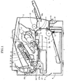
- the laser printer 1 includes a main casing 2, a feeder unit 4, and an image-forming unit 5.
- the main casing 2 houses the feeder unit 4 and the image-forming unit 5.
- the feeder unit 4 is for feeding recording sheets 3, and the image-forming unit 5 is for forming prescribed images on the recording sheet 3.
- the feeder unit 4 is disposed in the bottom section of the main casing 2 and includes a feed tray 6, a paper pressing plate 7, a feed roller 8, a separating pad 9, a pair of conveying rollers 10, a pair of conveying rollers 11, and a pair of registration rollers 12.
- the feed tray 6 is detachably mounted in the feeder unit 4.
- the paper pressing plate 7 is disposed in the feed tray 6.
- the feed roller 8 and the separating pad 9 are disposed above one end of the feed tray 6.
- the conveying rollers 10 and the conveying rollers 11 are provided downstream of the feed roller 8 in a sheet feed direction in which the recording sheet 3 is conveyed (hereinafter upstream or downstream in the sheet feed direction will be abbreviated as simply "upstream” or "downstream”).
- the registration rollers 12 are disposed downstream of the conveying rollers 10 and 11.
- a spring 13 is disposed on the underside of the paper pressing plate 7 for pressing the topmost recording sheet 3 on the paper pressing plate 7 against the feed roller 8.
- the conveying rollers 10 and 11 supply the recording sheet 3 fed by the feed roller 8 to the registration rollers 12.
- the registration rollers 12 supply the recording sheet 3 to the image-forming unit 5.
- the feeder unit 4 further includes a multipurpose tray 14, a multipurpose feed roller 15, and a multipurpose separating pad 15a.
- the multipurpose feed roller 15 is for feeding recording sheets 3 stacked on the multipurpose tray 14. As the multipurpose feed roller 15 rotates, the recording sheets 3 stacked on the conveying belt 14 becomes interposed between the multipurpose feed roller 15 and the multipurpose separating pad 15a and is fed one sheet at a time.
- the image-forming unit 5 includes a scanning unit 16, a process cartridge 17, a transfer roller 24, and a heat fixing unit 18.
- the scanning unit 16 is disposed in the top section of the main casing 2 and includes a laser light-emitting unit (not shown), a polygon mirror 19 that can be driven to rotate, lenses 20 and 21, and a reflecting mirror 22.
- the process cartridge 17 is disposed below the scanning unit 16 and is detachably mounted in the main casing 2.
- the process cartridge 17 includes a photosensitive drum 23, as well as a Scorotron charger, a developing roller, a toner accommodating unit, and the like (all of which are not shown in the drawings).
- the toner accommodating unit is filled with a positive-charge non-magnetic single-component polymer toner serving as developer.
- the toner is carried on the developing roller in a predetermined thin thickness.
- the photosensitive drum 23 is rotatably disposed in confrontation with the developing roller.
- the photosensitive drum 23 is formed of a drum body that is grounded.
- a surface of the photosensitive drum 23 is formed of a positively-charging photosensitive layer of polycarbonate or the like.
- the Scorotron charger applies a uniform positive charge across the entire surface of the photosensitive drum 23. Subsequently, the surface of the photosensitive drum 23 is exposed to high-speed scanning of a laser beam emitted from the scanning unit 16, forming electrostatic latent images on the surface based on prescribed image data.
- the positively charged toner carried on the surface of the developing roller is selectively supplied to the electrostatic latent image on the photosensitive drum 23, i.e., to areas of the surface of the uniformly charged photosensitive drum 23 that were exposed to the laser beam and, therefore, have a lower potential than the rest of the surface.
- the electrostatic latent images on the photosensitive drum 23 are transformed into visible toner images. In this way, a reverse development is performed.
- the transfer roller 24 is rotatably supported on the main casing 2 at a position below and in opposition to the photosensitive drum 23.
- the transfer roller 24 includes a metal roller shaft covered by a roller that is formed of an electrically conductive rubber material.
- a prescribed transfer bias with respect to the photosensitive drum 23 is applied to the transfer roller 24. Accordingly, the visible toner image on the photosensitive drum 23 is transferred to the recording sheet 3, as the recording sheet 3 passes between the photosensitive drum 23 and the transfer roller 24. After the visible toner image is transferred in this way, the recording sheet 3 is conveyed to the heat fixing unit 18 by a conveying belt 25.
- the heat fixing unit 18 is disposed downstream of the process cartridge 17 and includes a heat roller 26, a pressure roller 27, and a cleaning roller 27A.
- the pressure roller 27 is disposed opposing the heat roller 26 with the recording sheet 3 interposed therebetween.
- the cleaning roller 27A opposes the pressure roller 27.
- the peripheral surface of the pressure roller 27, which is not grounded, is covered with an insulating resin, such as a fluorocarbon resin.
- the cleaning roller 27A is rotatably supported and urged toward the pressure roller 27.
- the recording sheet 3 After being fixed in the heat fixing unit 18, the recording sheet 3 is conveyed to a pair of discharge rollers 30 by pairs of conveying rollers 28 and 29 disposed downstream of the heat fixing unit 18.
- the discharge rollers 30 subsequently discharge the recording sheet 3 onto a discharge tray 31.
- the control unit 40 includes a central processing unit (CPU) 41, a read only memory (ROM) 42, a random access memory (RAM) 43, an output interface 44, an input interface 45, a bus 48, a panel 49, and a printer engine 53.
- An external personal computer (PC) 47 is connected to the control unit 40 via the output interface 44 and the input interface 45 and can input image data of 300dpi or character data of 600dpi, as described later.
- the CPU 41 controls overall operations of the laser printer 1, including operations of the printer engine 53 (that is, the feeder unit 4 and the image-forming unit 5) and communications via the output interface 44 and the input interface 45, by executing various programs stored in the ROM 42 described later.
- the ROM 42 stores various control programs including a correction program described later.
- the ROM 42 includes a first correction table storage area 42A in which a first correction table 55 shown in Fig. 3 is stored.
- the first correction table 55 includes 600dpi binary data, 600dpi multi-value data, and first correction data. Details will be described later.
- the RAM 43 temporarily stores numerical values, programs, and the like that enable the CPU 41 to execute various control processes.
- the RAM 43 includes an input buffer 43A and an output buffer 43B.
- the RAM 43 also includes a 600dpi character data storage area 43C, a 600dpi binary data storage area 43D, a 300dpi character data storage area 43E, a 300dpi graphics data storage area 43F, a 300dpi superimposed data storage area 43G, a 600dpi converted data storage area 43H, a first correction data storage area 43I, and a second correction data storage area 43J.
- the 600dpi character data storage area 43C stores 600dpi character data.
- the 600dpi binary data storage area 43D sequentially stores 600dpi binary character shape data.
- the 300dpi character data storage area 43E sequentially stores character data that has been converted from 600dpi to 300dpi, while the 300dpi graphics data storage area 43F sequentially stores 300dpi graphics data superimposed one on the other.
- the 300dpi superimposed data storage area 43G sequentially stores 300dpi graphics data which is a composite data of 300dpi character data and 300dpi image data.
- the 600dpi converted data storage area 43H stores 600dpi graphics data that has been converted from 300dpi graphics data.
- the correction data storage area 43I stores graphics data that has undergone a first correction process.
- the second correction data storage area 43J stores graphics data that has undergone a second correction process.
- the areas 43C through 43J are initialized at startup.
- the output interface 44 and the input interface 45 are capable of connecting to the external PC 47 according to a parallel interface or a serial interface, or via a telephone line, a LAN, or the like.
- the bus 48 is a circuit for connecting the CPU 41, the output interface 44, the input interface 45, the ROM 42, the RAM 43, the panel 49, and the printer engine 53 to one another so that various data and signals can be exchanged among these components.
- the panel 49 is disposed on the top front of the main casing 2 and includes a liquid crystal display 50 and operating keys 51.
- the liquid crystal display 50 includes an LCD panel, by which the CPU 41 displays the current status of the laser printer 1 and other data.
- the laser printer 1 executes the image process when data is inputted from the external PC 47 for superimposing 600dpi character data and 300dpi image data and outputting the result.
- 600dpi character data, 300dpi image data, and another 600dpi character data are inputted in this order into the laser printer 1 from the external PC 47.
- the CPU 41 determines in S1 whether or not the inputted data is character data (600dpi character data). If so (S1:YES), then in S2, the CPU 41 temporarily stores the 600dpi character data and color (multi-value) data into the input buffer 43A. In S3, the CPU 41 creates 600dpi character shape data from the 600dpi character data temporarily stored in the input buffer 43A and stores the 600dpi character shape data into the 600dpi character data storage area 43C.
- the CPU 41 reads the 600dpi character shape data from the 600dpi character data storage area 43C, stores a "1" in the pixels of the 600dpi binary data storage area 43D corresponding to pixels in which the character shape data was stored, and stores a "0" in pixels of the 600dpi binary data storage area 43D corresponding to pixels in which no character shape data has been stored.
- the CPU 41 stores 600dpi binary character shape data in the 600dpi binary data storage area 43D.
- the data "1" is stored in each pixel of the 600dpi binary data storage area 43D corresponding to pixels of the 600dpi character data storage area 43C in which 600dpi character shape data has been stored, and the data "0" is stored in each pixel corresponding to pixels in which 600dpi character shape data has not been stored.
- 600dpi binary character shape data is created from the 600dpi character shape data and stored in the 600dpi binary data storage area 43D as shown in Fig. 5(B).
- the CPU 41 executes a resolution reducing process for converting the 600dpi character data stored in the input buffer 43A to 300dpi character data.
- Fig. 6 shows the flowchart representing the resolution reducing process.
- the CPU 41 consecutively reads four small pixels, including two pixels in the main scanning direction by two pixels in the sub-scanning direction, from the 600dpi character data stored in the input buffer 43A.
- the CPU 41 determines whether or not one or more of these four small pixels possesses color data or other character data. That is, the CPU 41 determines whether or not at least one of these four small pixels possesses color data or other character data. If one or more of the four small pixels possesses color data or other character data (S22:YES), then in S23, the CPU 41 stores the color data or other character data in a 300dpi pixel of the 300dpi character data storage area 43E corresponding to these four small pixels.
- the CPU 41 records no color data in a corresponding 300dpi pixel, that is, the CPU 41 does not store any data to the corresponding pixel in the 300dpi character data storage area 43E.
- the CPU 41 determines in S25 whether or not the four small pixels, including two pixels in the main scanning direction by two pixels in the sub-scanning direction, have been read for all 600dpi character data stored in the input buffer 43A. If not (S25:NO), then the process returns to S21. If so (S25:YES), then the CPU 41 ends the resolution reducing process and returns to S6 of Fig. 4.
- a pixel in the 300dpi character data stored in the 300dpi character data storage area 43E corresponds to a block of four small pixels in the 600dpi character data, including two pixels in the main scanning direction by two pixels in the sub-scanning direction, in the input buffer 43A.
- each pixel in the 300dpi character data stored in the 300dpi character data storage area 43E is divided by two in the main scanning direction and by two in the sub-scanning direction, each divided pixel corresponds to a single pixel in the 600dpi character data stored in the input buffer 43A.
- the CPU 41 reads 300dpi character data from the 300dpi character data storage area 43E, converts the color data or other character data in each pixel in the 300dpi character data to 8-bit multi-value data, and stores the 8-bit multi-value data as 300dpi graphics data (8-bit data) in the 300dpi superimposed data storage area 43G, overwriting the existing data (combining process).
- the CPU 41 determines in S7 whether or not data remains to be combined (whether all combining processes have been completed). If data remains to be combined (S7:YES), then the CPU 41 returns to S1, where the CPU 41 determines whether or not the second inputted data is character data (600dpi data). If the CPU 41 determines that the inputted data is not 600dpi character data (S1:NO), then this means that the second inputted data is 300dpi image data, and the CPU 41 temporarily stores the 300dpi image data in the input buffer 43A in S8.
- the CPU 41 converts the pixels in the 300dpi image data temporarily stored in the input buffer 43A into 8-bit multi-value data, thereby creating 300dpi graphics data (8-bit data), and stores the 300dpi graphics data in the 300dpi graphics data storage area 43F.
- the CPU 41 reads the 300dpi graphics data (8-bit data) from the 300dpi graphics data storage area 43F, stores the 300dpi graphics data in the 300dpi superimposed data storage area 43G by superimposing the data over the existing data (combining process), and then advances to S7.
- the 300dpi graphics data (8-bit data) shown in Fig. 8(B) is stored in the 300dpi superimposed data storage area 43G, and the 300dpi graphics data (8-bit data) shown in Fig. 9(A) is superimposed over the graphics data shown in Fig. 8(B) to generate composite graphics data (300dpi graphics data) shown in Fig. 9(B) in the 300dpi superimposed data storage area 43G.
- the CPU 41 determines whether any data remains to be combined (whether all combining processes have not been completed). If any data remains to be combined (S7:YES), then the CPU 41 returns to S1.
- the CPU 41 determines in S1 whether or not the third inputted data is character data (600dpi data). If the inputted data is determined to be 600dpi character data (S1:YES), then in S2, the CPU 41 temporarily stores the 600dpi character data and color (multi-value) data in the input buffer 43A.
- the CPU 41 creates 600dpi character shape data from the 600dpi character data temporarily stored in the input buffer 43A and stores the 300dpi character shape data in the 600dpi character data storage area 43C.
- the CPU 41 reads the 600dpi character shape data from the 600dpi character data storage area 43C and overwrites a "1" for each pixel in the 600dpi binary data storage area 43D corresponding to pixels in the 600dpi character shape data in which character shape data is stored.
- a "1" in the binary data storage area 43D receives priority regardless of the character shape data corresponding to the data being overwritten.
- the "1" is left unchanged regardless of whether the character shape data corresponding to the data to be overwritten is a "0" or a "1".
- the character shape data corresponding to the data to be overwritten is a "0” and a "1" has not been stored in the 600dpi binary data storage area 43D, then a "0" is stored.
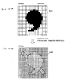
- the 600dpi binary character shape data shown in Fig. 5(B) is already stored in the 600dpi binary data storage area 43D, and the 600dpi character shape data shown in Fig. 10(A) is written according to the rules described above, so that 600dpi binary character shape data shown in Fig. 10(B) is stored in the 600dpi binary data storage area 43D.
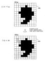
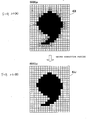
- the CPU 41 executes the resolution reducing process for converting the third inputted 600dpi character data shown in Fig. 11(A) stored in the input buffer 43A into 300dpi character data shown in Fig. 11 (B). More specifically, first in S21 of Fig. 6, the CPU 41 sequentially extracts four small pixels, including two pixels in the main scanning direction by two pixels in the sub-scanning direction, from the 600dpi character data stored in the input buffer 43A. If one or more of the four small pixels in the 600dpi character data includes color data or other character data (S22:YES), then the color data or other character data is recorded in a corresponding 300dpi pixel in the 300dpi character data storage area 43E (S23). However, if none of the four small pixels includes color data or other character data (822:NO), then nothing is stored in a corresponding 300dpi pixel in the 300dpi character data storage area 43E (S24).
- the CPU 41 again reads the 300dpi character data stored in the 300dpi character data storage area 43E, converts the color data or the like for each pixel of the 300dpi character data into 8-bit multi-value data, and superimposes the multi-value data over the existing data in the 300dpi superimposed data storage area 43G.
- color data and the like in each pixel of the 300dpi character data shown in Fig. 12(A) is converted to 8-bit multi-value data, and the 8-bit multi-value data is superimposed as 300dpi graphics data over the 300dpi graphics data (8-bit data) shown in Fig. 9(B) that is stored in the 600dpi superimposed data storage area 43G, thereby generating 300dpi graphics data in the 300dpi superimposed data storage area 43G as shown in Fig. 12(B).
- the CPU 41 determines in S7 whether data remains to be combined (whether all combining processes have not been completed). If data remains to be combined (S7:YES), then the CPU 41 returns to S1 and executes the process described above.
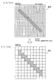
- the CPU 41 reads the 300dpi graphics data (8-bit data) from the 300dpi superimposed data storage area 43G, dividing each pixel in the 300dpi graphics data by two in the main scanning direction and two in the sub-scanning direction to obtain four small pixels for each pixel of the 300dpi graphics data and stores the 8-bit data of the pixel of the 300dpi graphics data into corresponding four pixels in the 600dpi converted data storage area 43H.
- 600dpi graphics data is stored in the 600dpi converted data storage area 43H as shown in Fig. 13(B).
- the CPU 41 executes the first correction process.
- the CPU 41 sequentially reads four small pixels (x1, x2, y1, y2), including two pixels in the main scanning direction by two pixels in the sub-scanning direction, from the 600dpi binary character shape data stored in the 600dpi binary data storage area 43D.
- the CPU 41 sequentially reads four small pixels (x11, x12, y11, y12), corresponding to the four small pixels (x1, x2, y1, y2) of the 600dpi binary character shape data, from the 600dpi graphics data (8-bit data) stored in the 600dpi converted data storage area 43H.
- the CPU 41 reads the first correction table 55 from the first correction table storage area 42A in the ROM 42.
- the CPU 41 stores the four small pixels (x1, x2,y1 , y2) of the 600dpi binary character shape data as four small pixels (X1, X2, Y1, Y2) of the "600dpi binary data" in the first correction table 55 (Fig. 3) and the four small pixels (x11, x12, y11, y12) as four small pixels (X11, X12, Y12, Y12) of the "600dpi multi-value data" in the first correction table 55.
- the CPU 41 sequentially creates four small pixels (X21, X22, X21, X22) of the "first correction data" in the first correction table 55, based on the corresponding four small pixels (X1, X2, Y1, Y2) of the "600dpi binary data” and corresponding four small pixels (X11, X12, Y12, Y12) of the "600dpi multi-value data", in a following manner.
- the binary data in the four small pixels (X1, X2, Y1, Y2) is (0, 0, 0, 0) or (1, 1, 1, 1)
- the multi-value data in the corresponding four small pixels (X21, X22, Y21, Y22) of the "first correction data" is assigned the multi-value data in the four small pixels (X11, X12, Y11, Y12) of the "600dpi multi-value data”.
- the pixel X21 of the "first correction data” is assigned the multi-value data in the pixel X11 of the "600dpi multi-value data", while the pixel X22 is assigned the multi-value data in the pixel X12 of the "600dpi multi-value data”.
- the pixel Y21 is assigned the multi-value data of the pixel Y11, while the pixel Y22 is assigned the multi-value data in the pixel Y12.
- pixels among (X21, X22, Y21, Y22) in the "first correction data" that correspond to a "1" in the binary data for the pixels (X1, X2, Y1, Y2) are assigned the multi-value data from the corresponding pixel (X11, X12, Y11, Y12).
- Pixels among (X21, X22, Y21, Y22) corresponding to a "0" in the binary data for the pixels (X1, X2, Y1, Y2) are not assigned multi-value data from the corresponding pixel (X11, X12, Y11, Y12), but blank data.
- the binary data for the four small pixels (X1, X2, Y1, Y2) is (0, 1, 1, 1)
- the pixel X21 of the "first correction data” is assigned blank-correction data
- the pixel X22 is assigned the multi-value data for the pixel X12.
- the pixels Y21 and Y22 are assigned the multi-value data for the pixels Y11 and Y12, respectively.
- first correction data which is 600dpi graphics data (8-bit data) is stored in the correction data storage area 43I.
- first correction data shown in Fig. 14(C) is created and stored in the correction data storage area 43I.
- 300dpi character data formed over the 600dpi graphics data is corrected to 600dpi character data.
- the CPU 41 executes a second correction process.
- the CPU 41 reads the first correction data from the correction data storage area 43I.
- the CPU 41 sequentially extracts in the main scanning direction each 600dpi pixel in the first correction data in which blank-correction data has been stored. If a pixel for image data (non-character pixels) is adjacent to the pixel possessing blank-correction data on the left or right, then the CPU 41 records the 600dpi graphics data from the outermost image-data pixel (non-character pixel) among the left and right adjacent pixels in place of the blank-correction data and stores the result as second correction data in the second correction data storage area 43J.
- pixels for image data are not adjacent to the pixel possessing the blank-correction data on the left and right, and if pixels for image data (non-character pixels) is adjacent to the pixel possessing blank-correction data on the above or below, then the blank-correction data is replaced by the 600dpi graphics data for the outermost image-data pixel (non-character pixel) from among the neighboring pixels above and below the pixel possessing the blank-correction data, and the result is stored in the second correction data storage area 43J as the second correction data. If pixels for image data (non-character pixel) are not adjacent to the pixel possessing the blank-correction data on the left, right, above, and below, then the blank-correction data is stored in the second correction data storage area 43J without being replaced.
- the 600dpi graphics data (8-bit data) for the pixel is recorded unchanged and stored as the second correction data in the second correction data storage area 43J.
- 600dpi graphics data for background image or the like is recorded in pixels in the correction data storage area 43I that corresponds to pixels in which blank-correction data was recorded during the first correction process of S12.
- the first correction data in the correction data storage area 43I shown in Fig. 15(A) is converted into second correction data and stored in the second correction data storage area 43J as shown in Fig. 15(B).
- the CPU 41 reads the second correction data from the second correction data storage area 43J and stores this data as print output data in the output buffer 43B.
- the superimposed 600dpi character data and 300dpi image data are both printed via the printer engine 53 at 600dpi printing density.
- the laser printer 1 receives 600dpi character data from the external PC 47, creates 600dpi binary character shape data from the 600dpi character data, and writes the 600dpi binary character shape data sequentially in the 600dpi binary data storage area 43D (S2-S4).
- the CPU 41 converts 600dpi character data and 300dpi image data inputted from the external PC 47 into 300dpi 8-bit multi-value graphics data and stores the same in the 300dpi superimposed data storage area 43G (S5, S6, S9, and S10). Then, the CPU 41 divides each pixel in the 300dpi 8-bit graphics data into four small pixels to create 600dpi 8-bit graphics data (S11).
- the 600dpi binary character shape data is subjected to the first and second correction processes using the first correction table 55, after which the superimposed 600dpi character data and 300dpi image data are both printed at 600dpi printing density (S12-S14).
- the 300dpi character data converted from 600dpi character data that is superimposed over 300dpi image data can be corrected to 600dpi character data. Accordingly, when a portion of the 600dpi character data overlaps the 300dpi image data, the portion of the 600dpi character can be combined and printed over a 300dpi photograph or background image with almost no change, resulting in a more satisfactory printing output.
- the second correction process corrects this problem by replacing blank-correction data with 8-bit multi-value data of a pixel representing the image or background from among pixels that are adjacent to pixels storing the blank-correction data. Accordingly, it is possible to improve the sharpness of a character having 600dpi resolution that is drawn over a 300dpi photograph or background image, resulting in a more satisfactory printing quality.
- the CPU 41 determines whether the inputted data is character data (600dpi data). If not (S1:NO), then this means that the inputted data is 300dpi image data, and the CPU 41 temporarily stores the 300dpi image data in the input buffer 43A (S8). In S9, the CPU 41 converts each pixel in the 300dpi image data temporarily stored in the input buffer 43A into 8-bit multi-value data to generate 300dpi graphics data (8-bit data) and stores this graphics data in the 300dpi graphics data storage area 43F as shown in Fig. 16(A).
- the CPU 41 reads the 300dpi graphics data (8-bit data) from the 300dpi graphics data storage area 43F and writes this data over existing data in the 300dpi superimposed data storage area 43G (S10) as shown in Fig. 16(B).
- the CPU 41 determines whether or not the second inputted data is character data (600dpi data). If so (S1:YES), then the CPU 41 temporarily stores the 600dpi character data and color (multi-value) data in the input buffer 43A in S2. The CPU 41 creates 600dpi character shape data from the 600dpi character data temporarily stored in the input buffer 43A and stores the generated data in the 600dpi character data storage area 43C (S3). Next, as shown in Figs. 17(A) and 17(B), the CPU 41 reads the 600dpi character shape data from the 600dpi character data storage area 43C and stores 600dpi binary character shape data in the 600dpi binary data storage area 43D (S4).
- S1:YES the CPU 41 temporarily stores the 600dpi character data and color (multi-value) data in the input buffer 43A in S2.
- the CPU 41 creates 600dpi character shape data from the 600dpi character data temporarily stored in the input buffer 43A and stores the generated data in the 600
- the CPU 41 records a "1" in each pixel of the 600dpi binary data storage area 43D corresponding to a pixel in which character shape data is stored and stores a "0" in each pixel of the 600dpi binary data storage area 43D corresponding to a pixel in which no character shape data is stored.
- the CPU 41 executes the resolution reducing process (S5) to convert the 600dpi character data shown in Fig. 18(A) to 300dpi character data shown in Fig. 18(B). That is, the CPU 41 generates 300dpi character data from the 600dpi character data temporarily stored in the input buffer 43A and stores the resulting data in the 300dpi character data storage area 43E.
- the CPU 41 reads the 300dpi character data stored in the 300dpi character data storage area 43E, converts color data and the like for each pixel in the 300dpi character data to 8-bit multi-value data, and stores the 8-bit multi-value data as 300dpi graphics data (8-bit data) in the 300dpi superimposed data storage area 43G over the existing data (S6).
- the CPU 41 reads the 300dpi graphics data (8-bit data) from the 300dpi superimposed data storage area 43G and divides each pixel by two in the main scanning direction and by two in the sub-scanning direction to generate four small pixels.
- the 8-bit multi-value data in the pixel of the 300dpi graphics data is stored in each of the corresponding divided four small pixels to generate 600dpi graphics data (8-bit data).
- the CPU 41 stores the 600dpi graphics data in the 600dpi converted data storage area 43H (S11).
- the CPU 41 executes the first correction process (S12) to create and store first correction data in the correction data storage area 43I shown in Fig. 21(C) from the 600dpi binary character shape data stored in the 600dpi binary data storage area 43D shown in Fig. 21(A) and the 600dpi graphics data stored in the 600dpi converted data storage area 43H shown in Fig. 21(B) by using the first correction table 55 in the manner described above.
- the CPU 41 executes the second correction process to create and store second correction data in the second correction data storage area 43J (S13). That is, the CPU 41 records 600dpi graphics data (8-bit data), such as a background image, in pixels corresponding to pixels of the first correction data in which blank-correction data was recorded in the first correction process.
- 600dpi graphics data 8-bit data
- the CPU 41 reads the second correction data from the second correction data storage area 43J and stores the second correction data as print output data in the output buffer 43B. Accordingly, the print output data is printed through the printer engine 53 at a uniform 600dpi printing density (S14).
- the entire 600dpi character can be combined and printed over a 300dpi photograph or background image with almost no change, resulting in a more satisfactory printing output.
- the conjoined area defining the character in the 300dpi character data stored in the 300dpi character data storage area 43E tends to expand (S21-S25).
- the conjoined area defining the character in the 300dpi character data stored in the 300dpi character data storage area 43E tends to compress.
- the CPU 41 determines in S22 whether one or more of four pixels of the 600dpi character data in the input buffer 43A possesses color data or other character data, and if any one or more of the four pixels possess color data or other data (S22:YES), then the process proceeds to S23, and if none of the four pixels possesses color data or other character data (822:NO), then the process proceeds to S24.
- the process in S22 of the first embodiment is replaced with a process for determining whether all of the four pixels possess color data or other character data. Then, if all of the four pixels possess color data or other character data, then the process proceeds to S23. On the other hand, if one or more of the four pixels does not possess color data or other character data, then the process proceeds to S24.
- the CPU 41 sequentially extracts in the main scanning direction 600dpi pixels from the first correction data stored in the correction data storage area 43I when the pixels possess blank-correction data that was stored in the first correction process of S12.
- the CPU 41 replaces the blank-correction data with character data (8-bit data) for the innermost 600dpi character pixel from among the pixels possessing the character data on the left and right or top and bottom.
- the resulting data is stored as second correction data in the second correction data storage area 43J.
- the laser printer 1 can correct 300dpi character data converted from 600dpi character data that has been superimposed on 300dpi image data back to 600dpi character data. Accordingly, when all or part of the 600dpi character data overlaps the 300dpi image data, the part or the entire 600dpi character can be combined and printed over a 300dpi photograph or background image with almost no change, resulting in a more satisfactory printing output.
- the second correction process corrects this problem by substituting 8-bit multi-value data for pixels representing the character from among pixels that are adjacent to pixels storing the blank-correction data. Accordingly, it is possible to improve the sharpness of a character having 600dpi resolution that is drawn over a 300dpi photograph or background image, resulting in a more satisfactory printing quality.
- the second correction process is executed in S13.
- the process of S13 is skipped when the resolution of character data inputted from the external PC 47 exceeds a prescribed resolution (for example 2400 dpi, 3600dpi, or 6000 dpi), and the first correction data produced from the first correction process of S12 is stored in the output buffer 43B as print output data and printed via the printer engine 53 at a uniform printing density of the corresponding resolution.
- a prescribed resolution for example 2400 dpi, 3600dpi, or 6000 dpi
- the second correction data storage area 43J Since the second correction data storage area 43J is unnecessary in this case, the storage capacity of the RAM 43 can be reduced, thereby improving image processing speed.
- monochromatic high-resolution character data is superimposed on low-resolution image data.
- present embodiment describes the case of superimposing color high-resolution character data on color low-resolution image data.
- color 600dpi character data is converted into 300dpi character data for each of the colors cyan (C), magenta (M), and yellow (Y), as shown in Figs. 23(A) and 23(B). Then, processes similar to that of the first embodiment are performed. That is, using the 300dpi character data for each color, the CPU 41 creates 600dpi multi-value graphics data corresponding to each of the colors cyan (C), magenta (M), and yellow (Y) through the processes of S6 and S11. However, in the process of S4 the CPU 41 creates only one unit of 600dpi binary character shape data for the color 600dpi character data.
- the CPU 41 performs the first correction process based on the 600dpi multi-value graphics data corresponding to each of the colors cyan (C), magenta (M), and yellow (Y) and the 600dpi binary character shape data. Subsequently, in the process of S13, the CPU 41 executes the second correction process for replacing blank-correction data in pixels of the 600dpi graphics data corresponding to each of the colors cyan (C), magenta (M), and yellow (Y).
- the entire color 600dpi character can be combined and printed with almost no change over the 300dpi color photograph or color background image.
- the high-resolution character data is converted to low-resolution character data corresponding to three colors. Accordingly, much less memory capacity is required than when converting high-resolution character data to high-resolution character data corresponding to three colors, thereby reducing manufacturing costs.
- monochromatic 600dpi character data is converted to 300dpi character data.
- color 600dpi character data is converted into 300dpi character data for each of the colors cyan (C), magenta (M), yellow (Y), and black (BK) as shown in Figs. 24(A) and 24(B).
- the subsequent processes are similar to those described in the first embodiment (S6-S14).
- the CPU 41 uses the 300dpi character data for each color of the colors black (BK), cyan (C), magenta (M), and yellow (Y), the CPU 41 creates 600dpi multi-value data corresponding to each of the colors black (BK), cyan (C), magenta (M), and yellow (Y) through the processes of S6 and S11. However, in the process of S4 the CPU 41 creates only one unit of 600dpi binary character shape data for the color 600dpi character data.
- the CPU 41 performs the first correction process based on the 600dpi multi-value data corresponding to each of the colors black (BK), cyan (C), magenta (M), and yellow (Y) and the 600dpi binary character shape data. Subsequently, in S13, the CPU 41 executes the second correction process for replacing blank-correction data in pixels of the 600dpi graphics data corresponding to each of the colors black (BK), cyan (C), magenta (M), and yellow (Y).
- the 600dpi graphics data corresponding to each of the colors black (BK), cyan (C), magenta (M), and yellow (Y) produced in the second correction process is stored in the output buffer 43B in S14, so that the entire color 600dpi character is combined and printed with almost no change over the 300dpi color photograph or color background image.
- the high-resolution character data is converted to low-resolution character data corresponding to four colors. Accordingly, much less memory capacity is required than when converting high-resolution character data to high-resolution character data corresponding to four colors, thereby reducing manufacturing costs.
- the character data need only be converted to a single unit of high-resolution binary data. Since the high-resolution character data need not be converted to character data corresponding to three or four colors, the required memory capacity can be greatly reduced, thereby reducing manufacturing costs.
Landscapes
- Engineering & Computer Science (AREA)
- Multimedia (AREA)
- Signal Processing (AREA)
- Editing Of Facsimile Originals (AREA)
- Image Processing (AREA)
- Controls And Circuits For Display Device (AREA)
- Color, Gradation (AREA)
Abstract
Description
Claims (8)
- An image-processing device comprising:a first converting means for converting a high-resolution character data to a high-resolution binary data;a first storing means for storing the high resolution character data;a second converting means for converting the high-resolution character data to a low-resolution character data;a second storing means for storing the low-resolution character data and a low-resolution image data as low-resolution composite data;a third converting means for converting the low-resolution composite data into a high-resolution multi-value composite data;a first correcting means for correcting the high-resolution multi-value composite data by using a logic filter table that employs the high-resolution binary data stored in the first memory; anda second correcting means for correcting the high-resolution multi-value composite data corrected by the first correcting means by assigning to blank pixels in the corrected high-resolution multi-value composite data that was generated when the first correcting means corrected the high-resolution multi-value composite data, one of a value of a pixel adjacent to the blank pixel and a blank value.
- The image-processing device according to claim 1, wherein if the second converting means has expanded a conjoined area defining a character in the low-resolution character data when converting the high-resolution character data to the low-resolution character data, then the second correcting means corrects the corrected high-resolution multi-value composite data by assigning to the blank pixel a value from among pixels adjacent to the blank pixel that indicates an image or background.
- The image-processing device according to claim 1, wherein if the second converting means has contracted a conjoined area defining a character in the low-resolution character data when converting the high-resolution character data to the low-resolution character data, then the second correcting means corrects the corrected high-resolution multi-value composite data by assigning to the blank pixel a value from among pixels adjacent to the blank pixel that indicates a character.
- The image-processing device according to any one of claims 1 to 3, wherein the high-resolution character data and the low-resolution image data are color data, and the second converting means converts the high-resolution character data to the low-resolution character data corresponding to three or four colors.
- An image-processing method for superimposing and outputting high-resolution character data and low-resolution image data, comprising:a) converting a high-resolution character data into a high-resolution binary data;b) developing and storing the high-resolution binary data in a high-resolution binary memory;c) converting the high-resolution character data to low-resolution character data;d) developing a low-resolution image data and the low-resolution character data converted from the high-resolution character data in a low-resolution multi-value memory, thereby storing a developed data in the low-resolution multi-value memory as a low-resolution composite data;e) converting the low-resolution composite data stored in the low-resolution multi-value memory into a high-resolution multi-value composite data;f) correcting the high-resolution multi-value composite data using a logic filter table that employs the high-resolution binary data stored in the high-resolution binary memory; andg) correcting the high-resolution multi-value composite data corrected in the step f) by assigning to a blank pixel in the high-resolution composite data generated through the step f) one of a value of a pixel adjacent to the blank pixel and a blank value.
- The image-processing method according to claim 5, wherein, in the step g), the blank pixel is assigned a value from among pixels adjacent to the blank pixel that indicates an image or background if a conjoined area defining the character in the low-resolution character data expands when the high-resolution character data is converted to the low-resolution character data in the step c).
- The image-processing method according to claim 5, in the step g), the blank pixel is assigned a value from among pixels adjacent to the blank pixel that indicates a character if a conjoined area defining the character in the low-resolution character data contracts when the high-resolution character data is converted to the low-resolution character data in the step c).
- The image-processing method according to any one of claims 5 to 7, wherein the high-resolution character data and the low-resolution image data are color data, and the low-resolution character data converted from the high-resolution character data in the step c) corresponds to three or four colors, and in the step d) the low-resolution character data corresponding to three or four colors is developed and stored in the low-resolution multi-value memory as the low-resolution composite data.
Applications Claiming Priority (2)
| Application Number | Priority Date | Filing Date | Title |
|---|---|---|---|
| JP2003093273A JP3849663B2 (en) | 2003-03-31 | 2003-03-31 | Image processing apparatus and image processing method |
| JP2003093273 | 2003-03-31 |
Publications (3)
| Publication Number | Publication Date |
|---|---|
| EP1471723A2 true EP1471723A2 (en) | 2004-10-27 |
| EP1471723A3 EP1471723A3 (en) | 2007-05-23 |
| EP1471723B1 EP1471723B1 (en) | 2016-11-30 |
Family
ID=32959526
Family Applications (1)
| Application Number | Title | Priority Date | Filing Date |
|---|---|---|---|
| EP04251858.9A Expired - Lifetime EP1471723B1 (en) | 2003-03-31 | 2004-03-29 | Image processing method for superimposing high-resolution character data on low-resolution image data |
Country Status (4)
| Country | Link |
|---|---|
| US (1) | US7355744B2 (en) |
| EP (1) | EP1471723B1 (en) |
| JP (1) | JP3849663B2 (en) |
| CN (2) | CN1275453C (en) |
Families Citing this family (17)
| Publication number | Priority date | Publication date | Assignee | Title |
|---|---|---|---|---|
| JP2004180099A (en) * | 2002-11-28 | 2004-06-24 | Matsushita Electric Ind Co Ltd | Image processing device |
| US20050213174A1 (en) * | 2004-02-27 | 2005-09-29 | Seiko Epson Corporation | Image processing system and image processing method |
| US8194277B2 (en) * | 2005-06-20 | 2012-06-05 | Canon Kabushiki Kaisha | Image combining apparatus, and control method and program therefor |
| JP2008009140A (en) * | 2006-06-29 | 2008-01-17 | Fujitsu Ltd | Image processing apparatus and image processing method |
| US8885208B2 (en) * | 2006-07-21 | 2014-11-11 | Adobe Systems Incorporated | Progressive refinement of an edited image using secondary high resolution image processing |
| US8254680B2 (en) | 2007-01-24 | 2012-08-28 | Samsung Electronics Co., Ltd. | Apparatus and method of segmenting an image in an image coding and/or decoding system |
| US20090040559A1 (en) * | 2007-08-10 | 2009-02-12 | Shuji Hamada | Image forming apparatus, image forming method, and image processing program |
| JP5020894B2 (en) * | 2008-06-10 | 2012-09-05 | キヤノン株式会社 | Image processing apparatus, control method, and program |
| JP4763027B2 (en) * | 2008-08-27 | 2011-08-31 | シャープ株式会社 | Image processing apparatus, image forming apparatus, image processing method, image processing program, and computer-readable recording medium |
| CN101409765B (en) * | 2008-10-21 | 2010-06-23 | 深圳市迅雷网络技术有限公司 | Image-processing method and apparatus |
| JP4748234B2 (en) * | 2009-03-05 | 2011-08-17 | 富士ゼロックス株式会社 | Image processing apparatus and image forming apparatus |
| JP5383416B2 (en) * | 2009-10-06 | 2014-01-08 | キヤノン株式会社 | Image processing apparatus, control method therefor, and program |
| JP2011250191A (en) * | 2010-05-27 | 2011-12-08 | Brother Ind Ltd | Line data correcting method and image forming apparatus |
| JP5754972B2 (en) * | 2011-02-15 | 2015-07-29 | キヤノン株式会社 | Image processing apparatus and image processing method |
| US8553286B2 (en) * | 2011-06-08 | 2013-10-08 | Electronics For Imaging, Inc. | Halftoning method and apparatus using templates indexed by code |
| US20130308874A1 (en) * | 2012-05-18 | 2013-11-21 | Kasah Technology | Systems and methods for providing improved data communication |
| US10972629B2 (en) * | 2019-09-11 | 2021-04-06 | Toshiba Tec Kabushiki Kaisha | Image processing apparatus configured to combine image information such that the combined first image information and second image information have the first resolution |
Family Cites Families (8)
| Publication number | Priority date | Publication date | Assignee | Title |
|---|---|---|---|---|
| US5781666A (en) | 1990-04-17 | 1998-07-14 | Canon Kabushiki Kaisha | Image processing method and apparatus suitable for both high-resolution and low-resolution image data |
| US6204935B1 (en) | 1994-08-26 | 2001-03-20 | Canon Kabushiki Kaisha | Image processing method and an image processing apparatus |
| JPH08139904A (en) | 1994-11-04 | 1996-05-31 | Canon Inc | Image processing method and apparatus |
| US5956470A (en) * | 1997-09-25 | 1999-09-21 | Xerox Corporation | Text quality enhancement via resolution enhancement technique based on separating jaggedness detection and filtering |
| US6563502B1 (en) * | 1999-08-19 | 2003-05-13 | Adobe Systems Incorporated | Device dependent rendering |
| US6982800B1 (en) | 2000-07-05 | 2006-01-03 | Lexmark International, Inc. | Apparatus and method for data management within a photoprinter |
| US7034963B2 (en) * | 2001-07-11 | 2006-04-25 | Applied Materials, Inc. | Method for adjusting edges of grayscale pixel-map images |
| US7046863B2 (en) * | 2002-03-25 | 2006-05-16 | Sharp Laboratories Of America, Inc. | Optimizing the advantages of multi-level rendering |
-
2003
- 2003-03-31 JP JP2003093273A patent/JP3849663B2/en not_active Expired - Fee Related
-
2004
- 2004-03-26 US US10/809,397 patent/US7355744B2/en not_active Expired - Fee Related
- 2004-03-29 EP EP04251858.9A patent/EP1471723B1/en not_active Expired - Lifetime
- 2004-03-31 CN CN200410034212.8A patent/CN1275453C/en not_active Expired - Fee Related
- 2004-03-31 CN CNU2004200424087U patent/CN2697982Y/en not_active Expired - Lifetime
Also Published As
| Publication number | Publication date |
|---|---|
| CN1275453C (en) | 2006-09-13 |
| EP1471723A3 (en) | 2007-05-23 |
| JP3849663B2 (en) | 2006-11-22 |
| JP2004304404A (en) | 2004-10-28 |
| US20040246507A1 (en) | 2004-12-09 |
| US7355744B2 (en) | 2008-04-08 |
| EP1471723B1 (en) | 2016-11-30 |
| CN1536872A (en) | 2004-10-13 |
| HK1066958A1 (en) | 2005-04-01 |
| CN2697982Y (en) | 2005-05-04 |
Similar Documents
| Publication | Publication Date | Title |
|---|---|---|
| EP1471723B1 (en) | Image processing method for superimposing high-resolution character data on low-resolution image data | |
| US6529643B1 (en) | System for electronic compensation of beam scan trajectory distortion | |
| EP2023598A1 (en) | Image processing device, image forming apparatus including same, image processing method | |
| JP5144161B2 (en) | Color image forming apparatus and color image forming method | |
| US8274707B2 (en) | Image processing apparatus, image processing method, and program for determining or computing an extended region of a block region of image data or an input image | |
| US20100103435A1 (en) | Image processing apparatus and image processing method for processing screen-processed image | |
| JP4865529B2 (en) | Image forming system, image forming apparatus, and image forming method therefor | |
| US20040150656A1 (en) | Image processing apparatus, image processing method, and image processing program | |
| US8441690B2 (en) | Image processing apparatus and image processing method for processing screen-processed image | |
| JP5517569B2 (en) | Image processing apparatus and image processing method | |
| JP3902907B2 (en) | Image processing apparatus and method, and image forming apparatus | |
| US8174551B2 (en) | Image forming apparatus and image forming method which utilizes a trapping process | |
| JP2004139011A (en) | Image processing apparatus, image processing method, and image processing program | |
| JP2008177882A (en) | Image processing device | |
| US5680226A (en) | Image recording apparatus | |
| US20080174797A1 (en) | Image forming device and method thereof | |
| JP2006295624A (en) | Image processing apparatus and method, and computer program and recording medium | |
| JP2006013769A (en) | Image output system, image output method, program for implementing the method, and computer-readable information recording medium recorded with the program | |
| US20030030827A1 (en) | Image processing apparatus and image forming apparatus | |
| US8446653B2 (en) | Image forming apparatus and image forming method which prevent toner from peeling from a secondary color area of a multicolor image while the image is on the photosensitive member of the apparatus | |
| JP4687593B2 (en) | Image processing apparatus and program | |
| JP2006014135A (en) | Image output system, image output method, program implementing the method and computer-readable information recording medium recorded with program | |
| JP2006171940A (en) | Printing system | |
| US5257115A (en) | Image recording apparatus using pseudo tone generated images | |
| JP5092422B2 (en) | Image forming apparatus and image processing apparatus |
Legal Events
| Date | Code | Title | Description |
|---|---|---|---|
| PUAI | Public reference made under article 153(3) epc to a published international application that has entered the european phase |
Free format text: ORIGINAL CODE: 0009012 |
|
| AK | Designated contracting states |
Kind code of ref document: A2 Designated state(s): AT BE BG CH CY CZ DE DK EE ES FI FR GB GR HU IE IT LI LU MC NL PL PT RO SE SI SK TR |
|
| AX | Request for extension of the european patent |
Extension state: AL HR LT LV MK |
|
| PUAL | Search report despatched |
Free format text: ORIGINAL CODE: 0009013 |
|
| AK | Designated contracting states |
Kind code of ref document: A3 Designated state(s): AT BE BG CH CY CZ DE DK EE ES FI FR GB GR HU IE IT LI LU MC NL PL PT RO SE SI SK TR |
|
| AX | Request for extension of the european patent |
Extension state: AL LT LV MK |
|
| 17P | Request for examination filed |
Effective date: 20071107 |
|
| AKX | Designation fees paid |
Designated state(s): AT BE BG CH CY CZ DE DK EE ES FI FR GB GR HU IE IT LI LU MC NL PL PT RO SE SI SK TR |
|
| 17Q | First examination report despatched |
Effective date: 20080206 |
|
| GRAP | Despatch of communication of intention to grant a patent |
Free format text: ORIGINAL CODE: EPIDOSNIGR1 |
|
| INTG | Intention to grant announced |
Effective date: 20160707 |
|
| GRAS | Grant fee paid |
Free format text: ORIGINAL CODE: EPIDOSNIGR3 |
|
| GRAA | (expected) grant |
Free format text: ORIGINAL CODE: 0009210 |
|
| AK | Designated contracting states |
Kind code of ref document: B1 Designated state(s): AT BE BG CH CY CZ DE DK EE ES FI FR GB GR HU IE IT LI LU MC NL PL PT RO SE SI SK TR |
|
| REG | Reference to a national code |
Ref country code: CH Ref legal event code: EP Ref country code: GB Ref legal event code: FG4D |
|
| REG | Reference to a national code |
Ref country code: AT Ref legal event code: REF Ref document number: 850767 Country of ref document: AT Kind code of ref document: T Effective date: 20161215 |
|
| REG | Reference to a national code |
Ref country code: IE Ref legal event code: FG4D |
|
| REG | Reference to a national code |
Ref country code: DE Ref legal event code: R096 Ref document number: 602004050395 Country of ref document: DE |
|
| REG | Reference to a national code |
Ref country code: FR Ref legal event code: PLFP Year of fee payment: 14 |
|
| REG | Reference to a national code |
Ref country code: NL Ref legal event code: MP Effective date: 20161130 |
|
| REG | Reference to a national code |
Ref country code: AT Ref legal event code: MK05 Ref document number: 850767 Country of ref document: AT Kind code of ref document: T Effective date: 20161130 |
|
| PG25 | Lapsed in a contracting state [announced via postgrant information from national office to epo] |
Ref country code: SE Free format text: LAPSE BECAUSE OF FAILURE TO SUBMIT A TRANSLATION OF THE DESCRIPTION OR TO PAY THE FEE WITHIN THE PRESCRIBED TIME-LIMIT Effective date: 20161130 Ref country code: GR Free format text: LAPSE BECAUSE OF FAILURE TO SUBMIT A TRANSLATION OF THE DESCRIPTION OR TO PAY THE FEE WITHIN THE PRESCRIBED TIME-LIMIT Effective date: 20170301 |
|
| PG25 | Lapsed in a contracting state [announced via postgrant information from national office to epo] |
Ref country code: PL Free format text: LAPSE BECAUSE OF FAILURE TO SUBMIT A TRANSLATION OF THE DESCRIPTION OR TO PAY THE FEE WITHIN THE PRESCRIBED TIME-LIMIT Effective date: 20161130 Ref country code: FI Free format text: LAPSE BECAUSE OF FAILURE TO SUBMIT A TRANSLATION OF THE DESCRIPTION OR TO PAY THE FEE WITHIN THE PRESCRIBED TIME-LIMIT Effective date: 20161130 Ref country code: PT Free format text: LAPSE BECAUSE OF FAILURE TO SUBMIT A TRANSLATION OF THE DESCRIPTION OR TO PAY THE FEE WITHIN THE PRESCRIBED TIME-LIMIT Effective date: 20170330 Ref country code: ES Free format text: LAPSE BECAUSE OF FAILURE TO SUBMIT A TRANSLATION OF THE DESCRIPTION OR TO PAY THE FEE WITHIN THE PRESCRIBED TIME-LIMIT Effective date: 20161130 Ref country code: AT Free format text: LAPSE BECAUSE OF FAILURE TO SUBMIT A TRANSLATION OF THE DESCRIPTION OR TO PAY THE FEE WITHIN THE PRESCRIBED TIME-LIMIT Effective date: 20161130 |
|
| PG25 | Lapsed in a contracting state [announced via postgrant information from national office to epo] |
Ref country code: NL Free format text: LAPSE BECAUSE OF FAILURE TO SUBMIT A TRANSLATION OF THE DESCRIPTION OR TO PAY THE FEE WITHIN THE PRESCRIBED TIME-LIMIT Effective date: 20161130 |
|
| PG25 | Lapsed in a contracting state [announced via postgrant information from national office to epo] |
Ref country code: CZ Free format text: LAPSE BECAUSE OF FAILURE TO SUBMIT A TRANSLATION OF THE DESCRIPTION OR TO PAY THE FEE WITHIN THE PRESCRIBED TIME-LIMIT Effective date: 20161130 Ref country code: DK Free format text: LAPSE BECAUSE OF FAILURE TO SUBMIT A TRANSLATION OF THE DESCRIPTION OR TO PAY THE FEE WITHIN THE PRESCRIBED TIME-LIMIT Effective date: 20161130 Ref country code: RO Free format text: LAPSE BECAUSE OF FAILURE TO SUBMIT A TRANSLATION OF THE DESCRIPTION OR TO PAY THE FEE WITHIN THE PRESCRIBED TIME-LIMIT Effective date: 20161130 Ref country code: SK Free format text: LAPSE BECAUSE OF FAILURE TO SUBMIT A TRANSLATION OF THE DESCRIPTION OR TO PAY THE FEE WITHIN THE PRESCRIBED TIME-LIMIT Effective date: 20161130 Ref country code: EE Free format text: LAPSE BECAUSE OF FAILURE TO SUBMIT A TRANSLATION OF THE DESCRIPTION OR TO PAY THE FEE WITHIN THE PRESCRIBED TIME-LIMIT Effective date: 20161130 |
|
| PG25 | Lapsed in a contracting state [announced via postgrant information from national office to epo] |
Ref country code: IT Free format text: LAPSE BECAUSE OF FAILURE TO SUBMIT A TRANSLATION OF THE DESCRIPTION OR TO PAY THE FEE WITHIN THE PRESCRIBED TIME-LIMIT Effective date: 20161130 Ref country code: BE Free format text: LAPSE BECAUSE OF FAILURE TO SUBMIT A TRANSLATION OF THE DESCRIPTION OR TO PAY THE FEE WITHIN THE PRESCRIBED TIME-LIMIT Effective date: 20161130 Ref country code: BG Free format text: LAPSE BECAUSE OF FAILURE TO SUBMIT A TRANSLATION OF THE DESCRIPTION OR TO PAY THE FEE WITHIN THE PRESCRIBED TIME-LIMIT Effective date: 20170228 |
|
| REG | Reference to a national code |
Ref country code: DE Ref legal event code: R097 Ref document number: 602004050395 Country of ref document: DE |
|
| PLBE | No opposition filed within time limit |
Free format text: ORIGINAL CODE: 0009261 |
|
| STAA | Information on the status of an ep patent application or granted ep patent |
Free format text: STATUS: NO OPPOSITION FILED WITHIN TIME LIMIT |
|
| REG | Reference to a national code |
Ref country code: CH Ref legal event code: PL |
|
| 26N | No opposition filed |
Effective date: 20170831 |
|
| PG25 | Lapsed in a contracting state [announced via postgrant information from national office to epo] |
Ref country code: SI Free format text: LAPSE BECAUSE OF FAILURE TO SUBMIT A TRANSLATION OF THE DESCRIPTION OR TO PAY THE FEE WITHIN THE PRESCRIBED TIME-LIMIT Effective date: 20161130 Ref country code: MC Free format text: LAPSE BECAUSE OF FAILURE TO SUBMIT A TRANSLATION OF THE DESCRIPTION OR TO PAY THE FEE WITHIN THE PRESCRIBED TIME-LIMIT Effective date: 20161130 |
|
| REG | Reference to a national code |
Ref country code: IE Ref legal event code: MM4A |
|
| PG25 | Lapsed in a contracting state [announced via postgrant information from national office to epo] |
Ref country code: LU Free format text: LAPSE BECAUSE OF NON-PAYMENT OF DUE FEES Effective date: 20170329 |
|
| REG | Reference to a national code |
Ref country code: FR Ref legal event code: PLFP Year of fee payment: 15 |
|
| PG25 | Lapsed in a contracting state [announced via postgrant information from national office to epo] |
Ref country code: LI Free format text: LAPSE BECAUSE OF NON-PAYMENT OF DUE FEES Effective date: 20170331 Ref country code: IE Free format text: LAPSE BECAUSE OF NON-PAYMENT OF DUE FEES Effective date: 20170329 Ref country code: CH Free format text: LAPSE BECAUSE OF NON-PAYMENT OF DUE FEES Effective date: 20170331 |
|
| PGFP | Annual fee paid to national office [announced via postgrant information from national office to epo] |
Ref country code: GB Payment date: 20180223 Year of fee payment: 15 |
|
| PGFP | Annual fee paid to national office [announced via postgrant information from national office to epo] |
Ref country code: FR Payment date: 20180223 Year of fee payment: 15 |
|
| PG25 | Lapsed in a contracting state [announced via postgrant information from national office to epo] |
Ref country code: HU Free format text: LAPSE BECAUSE OF FAILURE TO SUBMIT A TRANSLATION OF THE DESCRIPTION OR TO PAY THE FEE WITHIN THE PRESCRIBED TIME-LIMIT; INVALID AB INITIO Effective date: 20040329 |
|
| PG25 | Lapsed in a contracting state [announced via postgrant information from national office to epo] |
Ref country code: CY Free format text: LAPSE BECAUSE OF NON-PAYMENT OF DUE FEES Effective date: 20161130 |
|
| GBPC | Gb: european patent ceased through non-payment of renewal fee |
Effective date: 20190329 |
|
| PG25 | Lapsed in a contracting state [announced via postgrant information from national office to epo] |
Ref country code: GB Free format text: LAPSE BECAUSE OF NON-PAYMENT OF DUE FEES Effective date: 20190329 |
|
| PG25 | Lapsed in a contracting state [announced via postgrant information from national office to epo] |
Ref country code: FR Free format text: LAPSE BECAUSE OF NON-PAYMENT OF DUE FEES Effective date: 20190331 |
|
| PG25 | Lapsed in a contracting state [announced via postgrant information from national office to epo] |
Ref country code: TR Free format text: LAPSE BECAUSE OF FAILURE TO SUBMIT A TRANSLATION OF THE DESCRIPTION OR TO PAY THE FEE WITHIN THE PRESCRIBED TIME-LIMIT Effective date: 20161130 |
|
| PGFP | Annual fee paid to national office [announced via postgrant information from national office to epo] |
Ref country code: DE Payment date: 20200214 Year of fee payment: 17 |
|
| REG | Reference to a national code |
Ref country code: DE Ref legal event code: R119 Ref document number: 602004050395 Country of ref document: DE |
|
| PG25 | Lapsed in a contracting state [announced via postgrant information from national office to epo] |
Ref country code: DE Free format text: LAPSE BECAUSE OF NON-PAYMENT OF DUE FEES Effective date: 20211001 |