EP2023598A1 - Image processing device, image forming apparatus including same, image processing method - Google Patents
Image processing device, image forming apparatus including same, image processing method Download PDFInfo
- Publication number
- EP2023598A1 EP2023598A1 EP08161533A EP08161533A EP2023598A1 EP 2023598 A1 EP2023598 A1 EP 2023598A1 EP 08161533 A EP08161533 A EP 08161533A EP 08161533 A EP08161533 A EP 08161533A EP 2023598 A1 EP2023598 A1 EP 2023598A1
- Authority
- EP
- European Patent Office
- Prior art keywords
- image
- area
- density
- specific
- unit
- Prior art date
- Legal status (The legal status is an assumption and is not a legal conclusion. Google has not performed a legal analysis and makes no representation as to the accuracy of the status listed.)
- Withdrawn
Links
Images


Classifications
-
- H—ELECTRICITY
- H04—ELECTRIC COMMUNICATION TECHNIQUE
- H04N—PICTORIAL COMMUNICATION, e.g. TELEVISION
- H04N1/00—Scanning, transmission or reproduction of documents or the like, e.g. facsimile transmission; Details thereof
- H04N1/40—Picture signal circuits
- H04N1/407—Control or modification of tonal gradation or of extreme levels, e.g. background level
- H04N1/4072—Control or modification of tonal gradation or of extreme levels, e.g. background level dependent on the contents of the original
-
- H—ELECTRICITY
- H04—ELECTRIC COMMUNICATION TECHNIQUE
- H04N—PICTORIAL COMMUNICATION, e.g. TELEVISION
- H04N1/00—Scanning, transmission or reproduction of documents or the like, e.g. facsimile transmission; Details thereof
- H04N1/46—Colour picture communication systems
- H04N1/56—Processing of colour picture signals
- H04N1/60—Colour correction or control
- H04N1/6072—Colour correction or control adapting to different types of images, e.g. characters, graphs, black and white image portions
Definitions
- Exemplary aspects of the present invention generally relate to an image processing device, an image forming apparatus including the image processing device, an image processing method, and an image processing program.
- Related-art image forming apparatuses such as a copier, a facsimile machine, a printer, or a multifunction printer having two or more of copying, printing, scanning, and facsimile functions, form a toner image on a recording medium (e.g., a sheet) according to image data using an electrophotographic method.
- a recording medium e.g., a sheet
- a charger charges a surface of an image bearing member (e.g., a photoconductor); an optical scanning device emits a light beam onto the charged surface of the photoconductor to form an electrostatic latent image on the photoconductor according to the image data; the electrostatic latent image is developed with a developer (e.g., a toner) to form a toner image on the photoconductor; a transfer device transfers the toner image formed on the photoconductor onto a sheet; and a fixing device applies heat and pressure to the sheet bearing the toner image to fix the toner image onto the sheet.
- the sheet bearing the fixed toner image is then discharged from the image forming apparatus.
- some of the image forming apparatuses have a toner save mode for outputting an image with a smaller amount of an image forming material such as toner and ink to reduce consumption of the image forming material compared to that in the normal output mode.
- Examples of methods for reducing the consumption of the image forming material include a method for forming an image after reducing the density of an input image or obtaining a logical product of a dithered image and a decimation pattern of an input image, a method for modulating a pulse width and controlling an amount of writing light when forming an image, and so forth.
- the toner save mode is used when a higher quality image is not required, for example, when checking the layout of an output image. Nevertheless, it is still desirable to improve the quality of imaging even when the toner save mode is used.
- JP-A- 2001-219626 discloses a print system configured to reduce toner consumption by referring to object data, such as text, graphics, and photographs, associated with an image signal of an input image.
- object data such as text, graphics, and photographs
- an image part including the text, the graphics, and the photographs in the input image is specified based on the object data of the input image to reduce an amount of toner used for a part other than the image part while not reducing an amount of toner used for the image part.
- a certain level of legibility of the text can be maintained even though the total amount of toner used for outputting the image is reduced.
- the above-described processing is not performed on an input image with no object data, such as a scanner image read by an image reading device. Therefore, the print system is not applicable to an image forming apparatus such as a copier, in which the image reading device is included.
- JP-A-2005-059444 discloses an image forming apparatus configured to detect an edge part in an input image such that an amount of toner used for a non-edge part in the input image is reduced while not reducing an amount of toner used for the edge part. More specifically, an edge pixel in a scanner image read by an image reading device is detected by an edge detection unit such as a Laplacian filter so that the density of the detected edge pixel is maintained and the density of a non-edge pixel is reduced to output an image. Accordingly, in the image forming apparatus, the density of the edge part is kept relatively high even though the total amount of toner used for outputting the image is reduced, so that a certain level of legibility of text is maintained by emphasizing the edge part of the text. Moreover, the problem of the print system disclosed in JP-A-2001-219626 described above can be prevented.
- the above-described processing is also performed on an edge part included in an image without text, such as a photographic image. Consequently, the density of the edge part becomes relatively high while the density of a non-edge part becomes relatively low even in the image with no text.
- the inventors of the present invention have studied types of images which tend to include unnatural or odd parts when consumption of an image forming material such as toner is reduced. More specifically, consumption of the image forming material is not reduced for the edge part while reducing that for the non-edge part when outputting various types of images in a similar way as the processing performed in the image forming apparatus disclosed in JP-A-2005-059444 .
- the output images are evaluated by multiple evaluators to determine whether or not natural or odd parts are included therein.
- Results of the evaluation are illustrated in FIG. 1 .
- a degree of unnaturalness in output images found by the multiple evaluators differs depending on the contents of the output images. For example, all of the multiple evaluators found odd parts in an image including a human face. Specifically, a higher degree of unnaturalness is found in an output image of a face image area including a face image and a surrounding image when the density of an edge part is high and that of a non-edge part is low. A degree of unnaturalness is prominent particularly in an image including a face of an acquaintance. The reason is that outlines of hair and pupils are detected as the edge part due to having higher contrast with a background image so that density thereof becomes relatively high. By contrast, a skin portion is not detected as the edge part due to having lower contrast with the background image so that density thereof becomes relatively low. Consequently, only hair and pupils are emphasized, resulting in a higher degree of unnaturalness.
- an output image including man-made objects such as buildings and machinery has a lower degree of unnaturalness even when the density of the edge part is relatively high and that of the non-edge part is relatively low.
- An output image including nature such as landscape and plants also has a higher degree of unnaturalness as compared to the output image including the man-made object, although the degree of unnaturalness is lower than that in the output image of a human face.
- a specific image area including a face image area and an image area having images of nature such as landscape and plants has unnatural or odd parts when the density thereof is partially reduced as well as when the density of the non-edge part is reduced while that of the edge part is not reduced.
- an edge detection filter such as a Laplacian filter as in the case of the image forming apparatus disclosed in JP-A-2005-059444
- an outline of a character image having a complicated figure and a small character image may not be detected as an edge part.
- the outline of the character image may not be detected as an edge part.
- exemplary embodiments of the present invention provide an image processing device capable of reducing unnatural and odd parts from an output image when the density of the output image is partially reduced so as to reduce consumption of an image forming material, and improving legibility of a character image of which the outline is not detected as an edge part.
- exemplary embodiments of the present invention further provide an image forming apparatus including the image processing device, an image processing method, and an image processing program.
- an image processing device includes an image signal reception unit configured to receive an image signal of an image to be processed; a density reduction area detector configured to detect a density reduction area satisfying predetermined image density reduction requirements in the image to be processed based on the image signal received by the image signal reception unit; a specific image area detector configured to detect a specific image area satisfying predetermined specific image requirements different from the predetermined image density reduction requirements in the image to be processed based on the image signal received by the image signal reception unit; and a density controller configured to reduce density of the density reduction area detected by the density reduction area detector in a non-specific image area other than the specific image area detected by the specific image area detector, and to not reduce density of the density reduction area in the specific image area.
- Another exemplary embodiment provides an image forming apparatus including the image processing device described above and an image forming device configured to form an image on a recording material using an image forming material based on an image signal processed by the image processing device.
- Yet another exemplary embodiment provides an image processing method including receiving an image signal of an image to be processed; detecting a density reduction area satisfying predetermined image density reduction requirements in the image to be processed based on the image signal received in the receiving; detecting a specific image area satisfying predetermined specific image requirements different from the predetermined image density reduction requirements in the image to be processed based on the image signal received in the receiving; and reducing density of the density reduction area detected in the detecting the density reduction area in a non-specific image area other than the specific image area detected in the detecting the specific image area, and not reducing density of the density reduction area in the specific image area.
- Yet another exemplary embodiment provides an image processing program configured to cause a computer to perform the image processing method described above.
- paper is the medium from which is made a sheet on which an image is to be formed. It should be noted, however, that other printable media are available in sheets, and accordingly their use here is included. Thus, solely for simplicity, although this Detailed Description section refers to paper, sheets thereof, paper feeder, etc., it should be understood that the sheets, etc., are not limited only to paper but includes other printable media as well.
- the image forming apparatus is a composite machine including a copier and a printer configured to form an image based on image data read by a scanner and sent from an external device such as a personal computer.
- the present invention is also applicable to other image forming apparatuses, including, but not limited to, a copier, a printer, and a facsimile machine.
- FIG. 2 is a schematic view illustrating a configuration of the image forming apparatus according to the exemplary embodiments.
- An image forming apparatus 1000 forms an image on a transfer sheet S such as an OHP sheet, heavy paper including a card and a post card, and an envelope, as well as plain paper generally used for copying.
- the image forming apparatus 1000 mainly includes a scanner 6 and a printer 15.
- the printer 15 has a tandem configuration in which multiple photoconductors 1Y, 1C, 1M, and 1K (hereinafter collectively referred to as photoconductors 1) respectively corresponding to colors of yellow (Y), cyan (C), magenta (M), and black (K) configured to form images of each color are provided parallel to one another.
- the images of each color respectively formed on the photoconductors 1 are transferred onto the transfer sheet S conveyed by a transfer belt 5 serving as a movable recording medium conveyance member facing the photoconductors 1.
- Image formation performed in the image forming apparatus 1000 is described in detail below by taking the photoconductor 1Y and components provided around the photoconductor 1Y illustrated in FIG. 2 as a representative example.
- the photoconductors 1C, 1M, and 1K and components provided around the photoconductors 1C, M, and 1K respectively have the same configuration as that of the photoconductor 1Y and the components provided around the photoconductor 1Y. Therefore, for convenience, reference numerals corresponding to reference numerals assigned to the photoconductor 1Y and the components provided around the photoconductor 1Y are assigned to the photoconductors 1C, 1M, and 1K and the components provided around the photoconductors 1C, 1M, and 1K, and detailed descriptions thereof are omitted.
- a charger 2Y including a charging roller, an optical scanning device 20 serving as a latent image forming unit configured to direct laser light from a laser light source to a surface of the photoconductor 1Y to scan the surface of the photoconductor 1Y, a developing device 3Y, and a cleaning device 4Y are provided around the photoconductor 1Y along a rotation direction of the photoconductor 1Y as indicated by an arrow in FIG. 2 to form an image.
- the configuration and operation of the optical scanning device 20 are described in detail later.
- developing devices 3Y, 3C, 3M, and 3K are provided as illustrated in FIG. 2 so that toner colors of yellow, cyan, magenta, and black are respectively supplied, in that order, from a right side of an extended part of the transfer belt 5.
- the charger 2Y illustrated in FIG. 2 includes a charging roller, alternatively a corona discharge method using a discharge wire may be used for charging the surface of the photoconductor 1Y.
- the scanner 6 is provided above the printer 15 including the charger 2Y, the optical scanning device 20, the developing device 3Y, the cleaning device 4Y, and so forth.
- image data of an original document placed on an original document stand 6A is read by an image reading device 7.
- the image data thus read is output to an image processing device, not shown, to obtain data to be written to the optical scanning device 20.
- the image reading device 7 includes a light source 7A configured to scan the original document placed on the original document stand 6A, and multiple reflection mirrors 7C and an imaging lens 7D, each of which are configured to provide an image to multiple CCDs 7B provided corresponding to each color of reflected light from the original document. Image data corresponding to the intensity of the reflected light of each color is output from each of the multiple CCDs 7B to the image processing device. Configuration and operation of the image processing device are described in detail later.
- the transfer belt 5 provided in the printer 15 is a belt-type derivative including a polyester film extended around multiple rollers. A portion of the extended part of the transfer belt 5 faces each of the photoconductors 1Y, 1C, 1M, and 1Y, and transfer devices 8Y, 8C, 8M, and 8K (hereinafter collectively referred to as transfer devices 8) are respectively provided opposite the photoconductors 1Y, 1C, 1M, and 1K with the transfer belt 5 therebetween.
- the transfer sheet S is fed from a paper feed cassette 10A of a paper feed device 10 to the transfer belt 5 via a registration roller 9.
- the transfer sheet S thus fed is electrostatically attracted to the transfer belt 5 by a corona discharge from the transfer devices 8 and conveyed. Images carried by the photoconductors 1 are electrostatically attracted to the transfer sheet S by a positive corona discharge from the transfer devices 8.
- a neutralizing device 11 configured to neutralize the transfer sheet S is provided at a position through which the transfer sheet S having the images transferred from the photoconductors 1 thereon passes.
- Neutralizing devices 12 configured to neutralize the transfer belt 5 are provided facing each other with the transfer belt 5 therebetween, at the other extended part of the transfer belt 5.
- reference numeral 13 denotes a cleaning device configured to remove toner particles from the transfer belt 5.
- the neutralizing device 11 performs negative AC corona discharge from an upper surface of the transfer sheet S so as to neutralize electric charges on the transfer sheet S and release the transfer sheet S electrostatically attracted to the transfer belt 5 from the transfer belt 5.
- the transfer sheet S is separated from the transfer belt 5 by a curvature of the transfer belt 5, and simultaneously, scattering of toner caused by separation discharge, which occurs when removing the transfer sheet S from the transfer belt 5, can be prevented.
- the neutralizing devices 12 apply a negative AC corona discharge having a polarity opposite that of the charge applied from the transfer devices 8 to the transfer belt 5 from both front and back surfaces thereof, so that electric charges on the transfer belt 5 are electrically neutralized and the transfer belt 5 is prepared for a subsequent image forming operation.
- a surface of each of the photoconductors 1Y, 1C, 1M, and 1K is evenly charged by each of chargers 2Y, 2C, 2M, and 2K (hereinafter collectively referred to as chargers 2).
- chargers 2Y, 2C, 2M, and 2K hereinafter collectively referred to as chargers 2.
- electrostatic latent images are formed on the photoconductors 1 by the optical scanning device 20 based on the image data for each color read by the image reading device 7.
- the electrostatic latent images thus formed are developed with toner of each color supplied from developing devices 3Y, 3C, 3M, and 3K.
- the transfer devices 8 electrostatically transfer toner images of each color onto the transfer sheet S conveyed by the transfer belt 5.
- the transfer sheet S having the toner images of each color thereon is neutralized by the neutralizing device 11, and is separated from the transfer belt 5 using the curvature of the transfer belt 5. Subsequently, the transfer sheet S is conveyed to a fixing device 14 to fix the toner images on the transfer sheet S. Thereafter, the sheet S having the fixed toner image thereon is discharged to a discharge tray, not shown, attached to a main body of the image forming apparatus 1000.
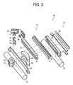
- FIG. 3 is a perspective view illustrating a configuration of the optical scanning device 20.
- optical scanning device 20 employs optical lenses, optical mirrors may be alternatively used.
- the optical scanning device 20 has a substantially symmetrical configuration with polygon mirrors 26 and 27 each serving as a deflection unit at a center thereof. Therefore, for convenience, only half of the optical scanning device 20 having the polygon mirrors 26 and 27 at the center thereof is illustrated in FIG. 3 and described in detail below.
- the optical scanning device 20 includes LD units 21 and 22 each having a laser light emitting element LD serving as a light source.
- the LD units 21 and 22 receive pulsed drive signals corresponding to image data output from the image processing device, and emit intermittent laser beams to the photoconductors 1Y and 1C to form dot latent images on the photoconductors 1Y and 1C.
- the optical scanning device 20 forms an image of the laser beams emitted from each of the LD units 21 and 22 on each of the photoconductors 1Y and 1C. Therefore, the optical scanning device 20 further includes optical element groups 51 and 52, each having multiple optical elements, respectively corresponding to the LD units 21 and 22 and the photoconductors 1Y and 1C. In other words, the optical scanning device 20 is provided corresponding to each of the photoconductors 1Y and 1C.
- the optical element group 51 includes multiple optical elements including a prism 40, a return mirror 23, a cylinder lens 24, a polygon mirror 26, a first scanning lens 28, return mirrors 31 and 32, a second scanning lens 30, and a return mirror 33.
- the optical element group 52 includes multiple optical elements including a prism 41, a cylinder lens 25, a polygon mirror 27, a first scanning lens 29, a second scanning lens 35, and return mirrors 36 and 37.
- the optical scanning device 20 further includes a holding member 61 for holding the second scanning lens 30 of the optical element group 51, and a holding member 62 for holding the second scanning lens 35 of the optical element group 52.
- a configuration of the holding member 61 and the second scanning lens 30 held by the holding member 61 is substantially the same as that of the holding member 62 and the second scanning lens 35 held by the holding member 62.
- Each of the LD units 21 and 22 is provided at a different height from each other in a vertical direction.
- the light beam emitted from the LD unit 21 provided at a higher position passes through the prism 40 serving as a writing start position correction unit. Subsequently, the light beam is bent by the return mirror 23 in a direction identical to a direction of the light beam emitted from the LD unit 22 provided at a lower position.
- the light beam emitted from the LD unit 22 passes through the prism 41 serving as a writing start position correction unit before entering the return mirror 23, and subsequently, passes through the return mirror 23.
- the light beam emitted from the LD unit 21 and the light beam emitted from the LD unit 22 enter the cylinder lenses 24 and 25, respectively, and are focused in the vicinity of reflection surfaces of the polygon mirrors 26 and 27, respectively.
- the polygon mirrors 26 and 27 are provided a predetermined distance apart in a vertical direction.
- the light beams deflected by the polygon mirrors 26 and 27 are shaped by the first scanning lenses 28 and 29, respectively.
- the first scanning lenses 28 and 29 are either integrally formed or superimposed on each other.
- the second scanning lenses 30 and 35 shape the light beams to have f ⁇ characteristics and a predetermined spot diameter, and the light beams thus shaped scan the surfaces of the photoconductors 1Y and 1C, respectively.
- optical paths of the light beams differ from each other such that the light beams are guided to the photoconductors 1Y and 1C, respectively.
- the light beam passing through the first scanning lens 28 provided at an upper position is bent by the return mirrors 31 and 32, and subsequently enters the second scanning lens 30 including a long plastic lens. Thereafter, the light beam is bent vertically downward so as to scan the surface of the photoconductor 1C in a main scanning direction.
- the light beam passing through the first scanning lens 29 provided at an lower position enters the second scanning lens 35 including a long plastic lens without entering a return mirror. Thereafter, an optical path of the light beam is bent by the return mirrors 36 and 37 so as to scan the surface of the photoconductor 1Y in a main scanning direction.
- the pulsed laser beams corresponding to the image data output from the image processing device emitted from the LD units 21 and 22 scan the surfaces of the photoconductors 1Y and 1C, respectively, so that dot latent images are formed on the surfaces of the photoconductors 1Y and 1C, respectively.
- the image processing device includes an image processing unit configured to process image data read by the image reading device 7 in the scanner 6, and an image processing unit configured to process image data sent from an external device such as a personal computer.
- Each of the image processing units is independently formed as a module. Since the present invention is applicable to both of the image processing units in a similar manner, only the configuration and operation of the former image processing unit is described in detail below. In the description below, a pixel value is represented by integers from 0 to 255, in which 0 represents the lowest density and 255 represents the highest density.
- a user operates an operation panel, not shown, provided on an outer surface of the image forming apparatus 1000 so that either a normal output mode or a toner save mode is selected.
- the toner save mode images are output with a smaller amount of toner, thereby reducing toner consumption.
- the user may select a type of an original document to be printed by operating the operation panel. Accordingly, operations of image processing and image formation may be appropriately changed in accordance with the type of the original document selected by the user.
- one of "text/photographic document”, "text document”, “photographic document”, and “map document” can be selected as a type of the original document by the user.
- the type of the original document may be determined automatically.
- a first exemplary embodiment of the image forming processing unit is described in detail below.
- FIG. 4 is a schematic view illustrating main components of an image processing unit 100 according to the first exemplary embodiment.
- Image data read by the image reading device 7 in the scanner 6 is output to a scanner gamma correction unit 101 of the image processing unit 100 as image signals of the colors red (R), green (G), and blue (B) (hereinafter referred to as R, G, and B signals, respectively).
- the scanner gamma correction unit 101 performs gamma correction specific to the image reading device 7 to convert the R, G, and B signals from a reflectance-linear signal into a density-linear signal, and outputs the R, G, and B signals thus converted to a scanner color correction unit 102.
- the scanner color correction unit 102 converts the R, G, and B signals which are device-dependent, that is, depend on characteristics of the image reading device 7, into R', G', and B' signals which are device-independent, that is, do not depend on the characteristics of any device, and outputs the R', G', and B' signals to a filter unit 103.
- the filter unit 103 performs smoothing and edge emphasis on the R', G', and B' signals so as to prevent moiré by suppressing irregularities at a halftone dot part and enhance sharpness of any text parts in the image. Thereafter, the filter unit 103 outputs the resultant R', G', and B' signals to a printer color correction unit 104.
- a degree of the above-described processing can be changed depending on a type of the original document selected by the user through the operation panel 70. Specifically, edges are highly emphasized to enhance sharpness of the text parts when the "text document” and the "map document” are selected by the user. In contrast, the image is highly smoothened to prevent moiré when the "photographic document” is selected. Meanwhile, when the "text/photographic document” is selected, edges are emphasized and the image is smoothed to an intermediate degree.
- the printer color correction unit 104 converts the R', G', and B' signals that are device-independent into C', M', and Y' signals which do depend on characteristics of the printer 15, and outputs the C', M', and Y' signals to a black component generation unit 105 and an edge detection unit 110.
- the black component generation unit 105 generates a K signal based on the C', M', and Y' signals in a process called black component generation, and removes undercolor by reducing amounts of each of the C', M', and Y' signals based on the K signal in a process called undercolor removal (UCR) to generate C, M, Y, and K signals.
- the C, M, Y, and K signals thus generated correspond to each color of toner in the printer 15, and are output to a toner save unit 106.
- FIG. 5 is a graph illustrating a lookup table (LUT) for black component generation.
- black component generation and undercolor removal may be performed using either an arithmetic expression or the LUT
- black component generation is performed using the LUT
- undercolor removal is performed using the arithmetic expression in the first exemplary embodiment.
- a minimum value Min(C', M', Y') of the C', M', and Y' signals is calculated to obtain an output value corresponding to the minimum value Min(C', M', Y') by referring to the LUT.
- undercolor removal is performed using arithmetic expressions (1) to (3) described below, where " ⁇ " represents a UCR adjustment parameter.
- a black component generation table 1 is used when "text document” or "map document” is selected so that the minimum value Min(C', M', Y') is replaced with the K signal and the UCR adjustment parameter ⁇ is set to 1.
- a black component table 3 is used to gradually generate the K signal from a halftone without generating the K signal at highlights. In this case, the UCR adjustment parameter ⁇ is set to 0.5.
- a black component table 2 is used to generate a larger amount of the K signal as compared to the case in which the "photographic document” is selected, and the UCR adjustment parameter ⁇ is set to 0.8.
- edge detection is performed based on the C', M', and Y' signals generated by the printer color correction unit 104, and density is reduced based on the detection result. Such processing is described in detail below.
- FIG. 6 is a schematic view illustrating a configuration of the edge detection unit 110.
- FIG. 7 is a schematic view illustrating a configuration of edge amount detection units 111C, 111M, and 111Y (hereinafter collectively referred to as edge amount detection units 111) in the edge detection unit 110.
- the edge detection unit 110 detects an area of which the density is to be reduced.
- Each of the edge amount detection units 111C, 111M, 111Y of the edge detection unit 110 detects an amount of multivalued edge for each of the C', M', and Y' signals.
- the edge amount detection filters 151 to 154 illustrated in FIG. 7 perform masking operations by using four types of 7x7 filters illustrated in FIGS. 8A to 8D , respectively. Thereafter, each of output values from the edge amount detection filters 151 to 154 is converted into an absolute value by each of absolute value conversion units 155 to 158.
- a first maximum value selection unit 159 selects a maximum absolute value from among the four absolute values thus converted to output as an edge amount to a second maximum value selection unit 112.
- the second maximum value selection unit 112 selects a maximum edge amount among the edge amounts of each color output from each of the edge amount detection unit 111C, 111M, and 111Y.
- the maximum edge amount thus selected is output to a binarization unit 113.
- the binarization unit 113 compares the maximum edge amount with a preset threshold, and outputs either 1 when the maximum edge amount is greater than the threshold or 0 when the maximum edge amount is smaller than the threshold.
- the C', M', and Y' signals input in the edge detection unit 110 are added together at a predetermined ratio in a signal synthesis unit 114 and synthesized into a single signal. More specifically, the signal synthesis unit 114 performs an operation of, for example, (C' x 1/4 + M' x 2/4 + Y' x 1/4), and outputs a resultant signal to a Laplacian filter operation unit 115 as a synthesized signal.
- the Laplacian filter operation unit 115 performs a masking operation on the synthesized signal by using a filter illustrated in FIG. 9 , and outputs a resultant value to a code determination unit 116.
- the code determination unit 116 determines whether or not the value input from the Laplacian filter operation unit 115 is a positive value or a negative value, and outputs 1 when the value is positive and 0 when the value is negative.
- a logical multiplication operation unit 117 performs logical multiplication on the output values from the binarization unit 113 and the code determination unit 116, and outputs either 1, indicating an edge part as an eg signal when a resultant value is 1 or 0 as an eg signal when the resultant value is not 1.
- the eg signal is output to a total determination unit 120 to be described in detail later.
- FIGS. 10A to 10D are views illustrating edge detection of a character image in an original document to be processed.
- the second maximum value selection unit 112 When an original document illustrated in FIG. 10A is subjected to edge detection, first, the second maximum value selection unit 112 outputs the maximum edge amount as a positive value as illustrated in FIG. 10B .
- the Laplacian filter operation unit 115 outputs Laplacian values such that a portion with higher density (inner portion of the character image) in the edge area of the character image becomes positive, and a portion with a lower density (outer portion of the character image) becomes negative, as illustrated in FIG. 10C .
- an edge part is detected based on not only the maximum edge amount output from the second maximum value selection unit 112 but also a code determined based on the Laplacian value.
- the inner portion of the character image in the edge area where the Laplacian value becomes positive is detected as an edge part, while the outer portion of the character image in the edge area where the Laplacian value becomes negative is not detected as an edge part as illustrated in FIG. 10D .
- a specific image such as a face image
- the specific image is not particularly limited to the face image as long as an image has any unnatural or odd parts when the density of the image is partially reduced.
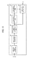
- FIG. 11 is a schematic view illustrating a configuration of a specific image detection unit 130 according to the first exemplary embodiment.
- the specific image detection unit 130 detects a specific image area. Specifically, the specific image detection unit 130 detects a face image based on AdaBoost.
- a luminance signal converter 131 converts the R', G', and B' signals output from the filter unit 103 into luminance signals, and outputs the luminance signals to a resolution converter 132. The conversion is performed based on an operational expression (4) described below.
- Y R ⁇ + 2 ⁇ G ⁇ + B ⁇ / 4
- the resolution converter 132 converts resolutions of the luminance signals, and outputs the luminance signals, of which resolutions are converted, to a rectangular area extraction unit 133.
- the resolutions of the luminance signals are converted into multiple one-half resolutions (2 X 2 pixels, skipping every other pixel) in each of a main scanning direction and a sub-scanning direction, or one-quarter resolutions in both the main scanning direction and the sub-scanning direction simultaneously.
- the rectangular area extraction unit 133 extracts a rectangular area from the luminance signal, of which resolution is thus converted.
- a rectangular area of 24 by 24 pixels is extracted from the luminance signal and is output to a face image identification unit 134.
- the face image identification unit 134 identifies whether or not the rectangular area of the luminance signal includes a face image.
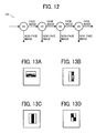
- the face image identification unit 134 using AdaBoost has a cascade configuration, in which multiple identifiers H1 to H4 are included as illustrated in FIG. 12 . Only when all of the multiple identifiers H1 to H4 determine that the rectangular area includes a face image, an image is identified as a face image.
- the identifiers H1 to H4 identify whether or not the rectangular area includes a face image by using characteristic quantity calculation filters each having a simple configuration as illustrated in FIGS. 13A to 13D . In FIGS. 13A to 13D , a white portion represents a white pixel, and a black portion represents a black pixel. More specifically, the identifier H1 employs a filter illustrated in FIG. 13A to obtain total pixel values of each of a white pixel area and a black pixel area in a rectangular area of 24 by 24 pixels, and a difference value therebetween.
- the identifier H1 determines whether or not the difference value satisfies certain requirements set by the user. When the difference value satisfies the requirements, identification is further performed by the identifier H2. On the other hand, when the difference value does not satisfy the requirements, the identifiers H1 determines that the rectangular area does not include a face image, and the identification process is terminated.
- the identifiers H2 to H4 sequentially perform identification by using the character quantity calculation filters illustrated in FIGS. 13B to 13D , respectively.
- the identifier H4 determines that the rectangular area includes a face image, it means that all of the identifiers H1 to H4 determine that the rectangular area includes a face image, so that a face image determination unit 135 determines that the rectangular area of 24 by 24 pixels includes a face image.
- AdaBoost AdaBoost
- an area data output unit 136 outputs an sp signal including data about the rectangular area such as coordinate data to specify the rectangular area.
- the face image area specified by the sp signal is, for example, an area circumscribed by a dotted line in an original document illustrated in FIG. 14 .
- AdaBoost AdaBoost Detection of a face image by using AdaBoost is described in detail in " Robust Face Detection for Low-Resolution Images” in the Journal of the Institute of Image Electronics Engineers of Japan 2005/11, Vol. 34, No. 6 (178 ), and therefore a further and more detailed description thereof is omitted here.
- the sp signal is output to the total determination unit 120 in a similar way as the eg signal.
- the total determination unit 120 outputs an edge determination signal ts indicating a total determination result based on the eg signal from the edge detection unit 110 and the sp signal from the specific image detection unit 130.
- an edge determination signal ts indicating a total determination result based on the eg signal from the edge detection unit 110 and the sp signal from the specific image detection unit 130.
- FIG. 15 illustrates a view in which only pixels detected as an edge part by the edge detection unit 110 in the original document illustrated in FIG. 14 are shown. As illustrated in FIG.
- an outer edge of a character image is detected as an edge part, and a portion having a higher contrast in a photographic image circumscribed by a solid line at a lower right part in FIG. 14 is also detected as an edge part. More specifically, in the photographic image, outlines of pupils and hair of a person and an outline of clothes having higher density are detected as an edge part.
- the total determination unit 120 is configured not to determine the edge part specified by the eg signal from the edge detection unit 110 as an edge part in the face image area specified by the sp signal from the specific image detection unit 130. In other words, pixels in the face image area are not determined as an edge part even when the pixels are detected as an edge part by the edge detection unit 110. Thereafter, the edge determination signal ts thus determined by the total determination unit 120 is output to a toner save unit 106. Pixels determined as an edge part specified by the edge determination signal ts are illustrated in FIG. 16 .
- the toner save unit 106 performs toner saving when the user selects a toner save mode. More specifically, when the user selects the toner save mode, the toner save unit 106 switches a type of the toner save mode based on a document type signal indicating the type of an original document from the operation panel 70, and the edge determination signal ts from the total determination unit 120.
- FIG. 17 is a graph illustrating characteristics of two types of ⁇ conversion used for toner saving.
- either one of the two types of ⁇ conversion, toner save ⁇ 1 and toner save ⁇ 2 illustrated in FIG. 17 is selected to perform ⁇ conversion to the C, M, Y, and K signals from the black component generation unit 105.
- ⁇ conversion is performed by using the toner save ⁇ 1
- an input value is identical to an output value so that density of the C, M, Y, and K signals are not changed. In other words, toner saving is not performed in such a case.
- the output value is substantially one-half of the input value, so that the density of the C, M, Y, and K signals is reduced.
- the toner save ⁇ 2 is applied regardless of an edge part and a non-edge part, as shown in Table 1 below, so that the density is evenly reduced to 50%.
- Table 1 shows an edge part and a non-edge part
- either one of the "text/photographic document”, the "text document”, and the “map document” is selected as a document type
- either the toner save ⁇ 1 or the toner save ⁇ 2 is applied in accordance with the edge determination signal ts as illustrated in Table 2 below.
- the toner save ⁇ 1 is applied to an edge part specified by the edge determination signal ts to maintain the density
- the toner save ⁇ 2 is applied to a non-edge part to reduce the density.
- the density of the edge part illustrated in FIG. 16 is maintained while the density of the non-edge part is reduced to 50%.
- legibility of the character image is improved while saving toner.
- the density of the face image area is evenly reduced to 50%.
- the density of the face image area is not locally reduced. Therefore, the density of the face image and an image adjacent to the face image as well as density of a portion such as hair and pupils conventionally detected as an edge part are evenly reduced.
- unnatural or odd parts in the face image can be reduced as compared to the case of the related art, in which hair and pupils of a person in the face image area are detected as an edge part to maintain the density of such portions as illustrated in FIG. 15 .
- the toner save ⁇ 2 is evenly applied to the face image area.
- unnatural or odd parts in the face image area can be reduced by evenly applying a same toner save ⁇ to the face image area.
- the toner save ⁇ 1 may be evenly applied to the face image area, or a toner save ⁇ which is different from the toner save ⁇ 1 and ⁇ 2 may be evenly applied to the face image area.
- the density of the edge part is maintained.
- the density of the edge part may be slightly reduced. In such a case, the density of the edge part is higher than that of the non-edge part.
- a printer gamma correction unit 107 performs gamma correction by using a density conversion table corresponding to density characteristics of the printer 15. Thereafter, a digital half-toning unit 108 performs digital half-toning, such as dithering and error diffusion, and outputs image data to a control unit of the printer 15.
- density conversion using the density conversion table is performed in two steps by the toner save unit 106 and the printer gamma correction unit 107.
- the density conversion may be integrally performed in one step.
- unnatural or odd parts in the face image can be reduced by evenly reducing the density of the face image area.
- the face image may not be identified when the density of the face image area is reduced too much. Therefore, it is preferable not to reduce the density of the face image area excessively.
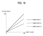
- a toner save ⁇ 3 having property intermediate between the toner save ⁇ 1 and ⁇ 2 as illustrated in FIG. 18 is provided.
- the toner save ⁇ 3 is evenly applied to the face image area as illustrated in Table 3 below.
- the toner save ⁇ 1 is applied to an edge part and the toner save ⁇ 2 is applied to a non-edge part in a similar way as the first exemplary embodiment.
- the image processing unit 100 according to the third exemplary embodiment has the same configuration as that of the image processing unit 100 according to the first exemplary embodiment illustrated in FIG. 4 , except that a specific image detection unit 140 detects a numeric image area as a specific image area instead of detecting the face image area.
- FIG. 19 is a schematic view illustrating the specific image detection unit 140 according to the third exemplary embodiment.
- the R', G', and B' signals output from the filter unit 103 are converted into luminance signals by a luminance signal converter 141, and resolutions of the luminance signals are converted by a resolution converter 142.
- a rectangular area extraction unit 143 extracts a rectangular area from the luminance signals of which resolutions are converted, and outputs the rectangular area to a numeric image identification unit 144.
- the numeric image identification unit 144 refers to characteristic quantity prestored in a dictionary memory 145 to identify whether or not a numeric image is included in the rectangular area.
- an area data output unit 146 When the numeric image is identified in the rectangular area by the numeric image identification unit 144, an area data output unit 146 outputs an sp signal including rectangular area data such as coordinate data to specify the rectangular area.
- a series of the processes from extraction of the rectangular area to identification of the numeric image are performed based on known OCR technology.
- the sp signal is output to the total determination unit 120 in a similar way as the eg signal.
- the total determination unit 120 outputs an edge determination signal ts indicating a total determination result based on the eg signal from the edge detection unit 110 and the sp signal from the specific image detection unit 140.
- the total determination unit 120 is configured not to determine the edge part specified by the eg signal from the edge detection unit 110 as an edge part in the numeric image area specified by the sp signal from the specific image detection unit 140. Specifically, pixels in the numeric image area are not determined as an edge part even when the pixels are detected as an edge part by the edge detection unit 110.
- the edge determination signal ts thus determined by the total determination unit 120 is output to the toner save unit 106.
- toner saving ⁇ 1 and toner save ⁇ 2 are used in toner saving according to the third exemplary embodiment.
- a toner save mode applied when any one of the "text/photographic document", the "text document”, and the "map document” is selected as a document type is shown in Table 4 below.
- the toner save ⁇ 1 is evenly applied to the numeric image area so as to maintain the density.
- the toner save ⁇ 1 is applied to the edge part and the toner save ⁇ 2 is applied to the non-edge part in a similar way as the first exemplary embodiment.
- FIG. 20 is a flow chart illustrating a flow of software processing performed in the image processing unit 100 according to a fourth exemplary embodiment.
- FIG. 20 illustrates an example of a case in which a series of processes performed by the edge detection unit 110, the total determination unit 120, the specific image detection unit 130, and the toner save unit 106 according to the first and second exemplary embodiments is performed by software. It should be noted that only main processes of the present invention are illustrated in the flow chart in FIG. 20 , with subsidiary processes omitted.
- a control unit including a CPU and so forth such as a processor and a memory provided in the image processing unit 100 runs an image processing program stored in a program memory such as a ROM to perform the following processes.
- the C', M', and Y' signals output from the printer color correction unit 104 are input into the control unit.
- the control unit detects an edge part based on the C', M', and Y' signals, and stores edge data indicating the edge part and a non-edge part for each pixel to an image memory.
- a face image area (a specific image area) including a face image is detected based on the C', M', and Y' signals.
- a type of ⁇ conversion to be applied is selected by referring to the result of edge detection (S2) stored in the image memory and the result of face image area detection (S3) to perform toner saving to the C', M', and Y' signals. More specifically, at S4, a determination is made as to whether or not the pixel to be processed belongs to the face image area based on the detection result of the face image area (S3). When the pixel to be processed is determined to belong to the face image area, at S5, toner saving is performed by applying the toner save ⁇ 2 illustrated in FIG. 17 to save toner consumption by reducing the density.
- the toner save ⁇ 1 illustrated in FIG. 17 is applied to perform toner saving by maintaining the density.
- the toner save ⁇ 2 illustrated in FIG. 17 is applied to reduce toner consumption by reducing the density.
- density of the entire face image area can be evenly reduced so that unnatural or odd parts in the face image can be reduced in a similar way as the first exemplary embodiment.
- the density of the non-edge part is reduced while maintaining the density of the edge part, thereby improving legibility of the character image.
- the toner save ⁇ 2 is applied to the face image area in the similar way as the first exemplary embodiment.
- the toner save ⁇ 3 illustrated in FIG. 18 may be applied to the face image area in the similar way as the second exemplary embodiment.
- the rest of the configuration according to the first exemplary embodiment may be also implemented by software.
- the image forming apparatus 1000 includes the image processing unit 100 and the printer 15 serving as an image forming unit configured to form an image on the transfer sheet S using an image forming material such as toner based on an image signal processed by the image processing unit 100.
- the image processing unit 100 includes the scanner gamma correction unit 101 configured to receive the image signals (R, G, and B signals) of the original document to be processed; an edge detection unit 110 configured to detect a non-edge part which satisfies predetermined requirements in the original document based on the image signal received by the scanner gamma correction unit 101 to reduce the density of the non-edge part; the specific image detection unit 130 configured to detect a face image area which satisfies predetermined requirements in the original document based on the image signal received by the scanner gamma correction unit 101; and the total determination unit 120 and the toner save unit 106 configured to perform toner saving to the non-face image area detected by the specific image detection unit 130 to reduce the density of the non-edge part detected by the edge detection unit 110, and not to perform toner saving to the non-edge part included in the face image area.
- the scanner gamma correction unit 101 configured to receive the image signals (R, G, and B signals) of the original document to be processed
- an edge detection unit 110 configured to detect
- the density of the face image area is not partially reduced, thereby reducing unnatural or odd parts in the output image.
- the density of the non-edge part is reduced while maintaining the density of the edge part, thereby improving legibility of the character image while reducing toner consumption.
- the area detected by the edge detection unit 110 to reduce the density thereof is the non-edge part of the original document, so that the density of the non-edge part is relatively reduced while keeping the density of the edge part relatively high in the non-face image area. Accordingly, legibility of the character image can be improved while reducing toner consumption.
- the density of the non-face image area is partially reduced for the purpose of achieving another effects, the face image area is not affected by such process so that unnatural or odd parts in the output image can be reduced.
- the face image area which may include unnatural or odds parts when the density thereof is partially reduced is detected as a specific image area by the specific image detection unit 130. Accordingly, unnatural or odd parts in the output image can be effectively reduced.
- the toner save unit 106 performs toner saving to evenly reduce the density of the face image area detected by the specific image detection unit 130.
- the density of the face image area may be maintained without performing toner saving to reduce the density thereof. In such a case, visibility of the face image can be more highly improved.
- the toner save unit 106 performs toner saving to evenly reduce the density of the entire face image area detected by the specific image detection unit 130 with a lower reduction rate as compared to a reduction rate for the density of the non-face image area. Accordingly, visibility of the face image in the output image can be highly improved while reducing toner consumption.
- the image processing unit 100 includes the scanner gamma correction unit 101 configured to receive the image signals (R, G, and B signals) of the original document to be processed; the edge detection unit 110 configured to detect the edge part which satisfies predetermined requirements in the original document based on the image signals received by the scanner gamma correction unit 101; the specific image detection unit 140 configured to detect a numeric image area which satisfies predetermined requirements in the original document as a specific image area based on the image signals received by the scanner gamma correction unit 101; and the total determination unit 120 and the toner save unit 106 configured to perform toner saving to the non-numeric image area detected by the specific image detection unit 140 so as to reduce the density of the non-edge part detected by the edge detection unit 110, and perform toner saving to the numeric image area such that the density of the numeric image area is evenly kept higher than the density of the non-edge part of the non-numeric image area.
- the scanner gamma correction unit 101 configured to receive the image signals (R, G
- Such a configuration allows the specific image detection unit 140 to recognize small numerical images of which outlines are hardly detected as an edge part by the edge detection unit 110 and numerical images with a lower contrast with adjacent images.
- the numerical images detected by the specific image detection unit 140 can evenly have relatively high density. Therefore, legibility of the small numerical images and the numerical images with a lower contrast with the adjacent images can be improved. Not only legibility of the numerical images described above but also legibility of small character image and character images with a lower contrast with adjacent images can be improved by allowing the specific image detection unit 140 to recognize such character images.
- the foregoing exemplary embodiments are applied to the image forming apparatus using electrophotography to reduce toner consumption in the description above, the foregoing exemplary embodiments may also be applied to an inkjet image forming apparatus using an image forming material other than toner.
Abstract
Description
- The present patent application is based on and claims priority pursuant to 35 U.S.C. §119 from Japanese Patent Application No.
2007-198708, filed on July 31, 2007 - Exemplary aspects of the present invention generally relate to an image processing device, an image forming apparatus including the image processing device, an image processing method, and an image processing program.
- Related-art image forming apparatuses, such as a copier, a facsimile machine, a printer, or a multifunction printer having two or more of copying, printing, scanning, and facsimile functions, form a toner image on a recording medium (e.g., a sheet) according to image data using an electrophotographic method. In such a method, for example, a charger charges a surface of an image bearing member (e.g., a photoconductor); an optical scanning device emits a light beam onto the charged surface of the photoconductor to form an electrostatic latent image on the photoconductor according to the image data; the electrostatic latent image is developed with a developer (e.g., a toner) to form a toner image on the photoconductor; a transfer device transfers the toner image formed on the photoconductor onto a sheet; and a fixing device applies heat and pressure to the sheet bearing the toner image to fix the toner image onto the sheet. The sheet bearing the fixed toner image is then discharged from the image forming apparatus.
- In addition to a normal output mode for generating and outputting a high-quality image, some of the image forming apparatuses have a toner save mode for outputting an image with a smaller amount of an image forming material such as toner and ink to reduce consumption of the image forming material compared to that in the normal output mode. Examples of methods for reducing the consumption of the image forming material include a method for forming an image after reducing the density of an input image or obtaining a logical product of a dithered image and a decimation pattern of an input image, a method for modulating a pulse width and controlling an amount of writing light when forming an image, and so forth. However, because the image is output after reducing density in the above-described methods, the quality of the output image is degraded compared to that in the normal output mode. In general, the toner save mode is used when a higher quality image is not required, for example, when checking the layout of an output image. Nevertheless, it is still desirable to improve the quality of imaging even when the toner save mode is used.
- Published unexamined Japanese Patent application No. (hereinafter referred to as JP-A-)
2001-219626 - In another approach,
JP-A-2005-059444 JP-A-2001-219626 - However, in the image forming apparatus, the above-described processing is also performed on an edge part included in an image without text, such as a photographic image. Consequently, the density of the edge part becomes relatively high while the density of a non-edge part becomes relatively low even in the image with no text. After a study performed by the inventors of the present invention, it has been found out that unnatural or odd parts may be included in the image with no text output from the image forming apparatus depending on contents of the output image.
- The inventors of the present invention have studied types of images which tend to include unnatural or odd parts when consumption of an image forming material such as toner is reduced. More specifically, consumption of the image forming material is not reduced for the edge part while reducing that for the non-edge part when outputting various types of images in a similar way as the processing performed in the image forming apparatus disclosed in
JP-A-2005-059444 - Results of the evaluation are illustrated in
FIG. 1 . - After the evaluation, the inventors of the present invention have determined that a degree of unnaturalness in output images found by the multiple evaluators differs depending on the contents of the output images. For example, all of the multiple evaluators found odd parts in an image including a human face. Specifically, a higher degree of unnaturalness is found in an output image of a face image area including a face image and a surrounding image when the density of an edge part is high and that of a non-edge part is low. A degree of unnaturalness is prominent particularly in an image including a face of an acquaintance. The reason is that outlines of hair and pupils are detected as the edge part due to having higher contrast with a background image so that density thereof becomes relatively high. By contrast, a skin portion is not detected as the edge part due to having lower contrast with the background image so that density thereof becomes relatively low. Consequently, only hair and pupils are emphasized, resulting in a higher degree of unnaturalness.
- On the other hand, an output image including man-made objects such as buildings and machinery has a lower degree of unnaturalness even when the density of the edge part is relatively high and that of the non-edge part is relatively low. An output image including nature such as landscape and plants also has a higher degree of unnaturalness as compared to the output image including the man-made object, although the degree of unnaturalness is lower than that in the output image of a human face.
- A specific image area including a face image area and an image area having images of nature such as landscape and plants has unnatural or odd parts when the density thereof is partially reduced as well as when the density of the non-edge part is reduced while that of the edge part is not reduced.
- When the edge part is detected by an edge detection filter such as a Laplacian filter as in the case of the image forming apparatus disclosed in
JP-A-2005-059444 JP-A-2005-059444 - In view of the foregoing, exemplary embodiments of the present invention provide an image processing device capable of reducing unnatural and odd parts from an output image when the density of the output image is partially reduced so as to reduce consumption of an image forming material, and improving legibility of a character image of which the outline is not detected as an edge part. Exemplary embodiments of the present invention further provide an image forming apparatus including the image processing device, an image processing method, and an image processing program.
- In one exemplary embodiment, an image processing device includes an image signal reception unit configured to receive an image signal of an image to be processed; a density reduction area detector configured to detect a density reduction area satisfying predetermined image density reduction requirements in the image to be processed based on the image signal received by the image signal reception unit; a specific image area detector configured to detect a specific image area satisfying predetermined specific image requirements different from the predetermined image density reduction requirements in the image to be processed based on the image signal received by the image signal reception unit; and a density controller configured to reduce density of the density reduction area detected by the density reduction area detector in a non-specific image area other than the specific image area detected by the specific image area detector, and to not reduce density of the density reduction area in the specific image area.
- Another exemplary embodiment provides an image forming apparatus including the image processing device described above and an image forming device configured to form an image on a recording material using an image forming material based on an image signal processed by the image processing device.
- Yet another exemplary embodiment provides an image processing method including receiving an image signal of an image to be processed; detecting a density reduction area satisfying predetermined image density reduction requirements in the image to be processed based on the image signal received in the receiving; detecting a specific image area satisfying predetermined specific image requirements different from the predetermined image density reduction requirements in the image to be processed based on the image signal received in the receiving; and reducing density of the density reduction area detected in the detecting the density reduction area in a non-specific image area other than the specific image area detected in the detecting the specific image area, and not reducing density of the density reduction area in the specific image area.
- Yet another exemplary embodiment provides an image processing program configured to cause a computer to perform the image processing method described above.
- Additional features and advantages of the present invention will be more fully apparent from the following detailed description of exemplary embodiments, the accompanying drawings, and the associated claims.
- A more complete appreciation of the disclosure and many of the attendant advantages thereof will be readily obtained as the same becomes better understood by reference to the following detailed description of exemplary embodiments when considered in connection with the accompanying drawings, wherein:
-
FIG. 1 is a graph illustrating a result of an evaluation performed by multiple evaluators to study a degree of unnaturalness found in various types of output images; -
FIG. 2 is a schematic view illustrating a configuration of an image forming apparatus according to exemplary embodiments; -
FIG. 3 is a perspective view illustrating a configuration of an optical scanning device in the image forming apparatus; -
FIG. 4 is a schematic view illustrating main components of an image processing unit according to a first exemplary embodiment; -
FIG. 5 is a graph illustrating a lookup table (LUT) for black component generation; -
FIG. 6 is a schematic view illustrating a configuration of an edge detection unit in the image processing unit; -
FIG. 7 is a schematic view illustrating an edge amount detection unit in the edge detection unit; -
FIGS. 8A to 8D are views illustrating four types of filters used as edge amount detection filters of the edge amount detection unit; -
FIG. 9 is a view illustrating a filter used in a Laplacian filter operation unit of the edge amount detection unit; -
FIGS. 10A to 10D are views illustrating edge detection of a character image in an original document; -
FIG. 11 is a schematic view illustrating a specific image detection unit in the image processing unit; -
FIG. 12 is a schematic view illustrating a configuration of a face image identification unit in the specific image detection unit; -
FIGS. 13A to 13D are views illustrating characteristic quantity calculation filters respectively used in four identifiers in the face image identification unit; -
FIG. 14 is a view illustrating an example of an original document; -
FIG. 15 is a view in which only pixels in the original document detected as an edge part by the edge detection unit are shown; -
FIG. 16 is a view in which only pixels in the original document detected as an edge part by a total determination unit after consideration of a recognition result of a face image area are shown; -
FIG. 17 is a graph illustrating characteristics of two types of γ conversion used in a toner save unit in the image processing unit; -
FIG. 18 is a graph illustrating characteristics of three types of γ conversion used in a toner save unit according to a second exemplary embodiment; -
FIG. 19 is a schematic view illustrating a specific image detection unit according to a third exemplary embodiment; and -
FIG. 20 is a flow chart illustrating a flow of software processing performed in an image processing unit according to a fourth exemplary embodiment. - In describing exemplary embodiments illustrated in the drawings, specific terminology is employed for the sake of clarity. However, the disclosure of this patent specification is not intended to be limited to the specific terminology so selected, and it is to be understood that each specific element includes all technical equivalents that operate in a similar manner and achieve a similar result.
- Exemplary embodiments of the present invention are now described below with reference to the accompanying drawings.
- In a later-described comparative example, exemplary embodiment, and exemplary variation, for the sake of simplicity the same reference numerals will be given to identical constituent elements such as parts and materials having the same functions, and redundant descriptions thereof omitted unless otherwise stated.
- Typically, but not necessarily, paper is the medium from which is made a sheet on which an image is to be formed. It should be noted, however, that other printable media are available in sheets, and accordingly their use here is included. Thus, solely for simplicity, although this Detailed Description section refers to paper, sheets thereof, paper feeder, etc., it should be understood that the sheets, etc., are not limited only to paper but includes other printable media as well.
- A description is now given of exemplary embodiments of a tandem type color laser composite machine using electrophotography (hereinafter simply referred to as image forming apparatus) in which multiple latent image bearing members each serving as a photoconductor are arranged parallel to one another.
- The image forming apparatus according to the exemplary embodiments is a composite machine including a copier and a printer configured to form an image based on image data read by a scanner and sent from an external device such as a personal computer. Needless to say, the present invention is also applicable to other image forming apparatuses, including, but not limited to, a copier, a printer, and a facsimile machine.
-
FIG. 2 is a schematic view illustrating a configuration of the image forming apparatus according to the exemplary embodiments. - An
image forming apparatus 1000 forms an image on a transfer sheet S such as an OHP sheet, heavy paper including a card and a post card, and an envelope, as well as plain paper generally used for copying. Theimage forming apparatus 1000 mainly includes ascanner 6 and aprinter 15. - The
printer 15 has a tandem configuration in whichmultiple photoconductors photoconductors 1 are transferred onto the transfer sheet S conveyed by atransfer belt 5 serving as a movable recording medium conveyance member facing thephotoconductors 1. - Image formation performed in the
image forming apparatus 1000 is described in detail below by taking thephotoconductor 1Y and components provided around thephotoconductor 1Y illustrated inFIG. 2 as a representative example. The photoconductors 1C, 1M, and 1K and components provided around thephotoconductors 1C, M, and 1K respectively have the same configuration as that of thephotoconductor 1Y and the components provided around thephotoconductor 1Y. Therefore, for convenience, reference numerals corresponding to reference numerals assigned to thephotoconductor 1Y and the components provided around thephotoconductor 1Y are assigned to thephotoconductors photoconductors - A charger 2Y including a charging roller, an
optical scanning device 20 serving as a latent image forming unit configured to direct laser light from a laser light source to a surface of thephotoconductor 1Y to scan the surface of thephotoconductor 1Y, a developing device 3Y, and acleaning device 4Y are provided around thephotoconductor 1Y along a rotation direction of thephotoconductor 1Y as indicated by an arrow inFIG. 2 to form an image. The configuration and operation of theoptical scanning device 20 are described in detail later. - Developing
devices FIG. 2 so that toner colors of yellow, cyan, magenta, and black are respectively supplied, in that order, from a right side of an extended part of thetransfer belt 5. Although the charger 2Y illustrated inFIG. 2 includes a charging roller, alternatively a corona discharge method using a discharge wire may be used for charging the surface of thephotoconductor 1Y. - In the
image forming apparatus 1000, thescanner 6 is provided above theprinter 15 including the charger 2Y, theoptical scanning device 20, the developing device 3Y, thecleaning device 4Y, and so forth. In thescanner 6, image data of an original document placed on an original document stand 6A is read by animage reading device 7. The image data thus read is output to an image processing device, not shown, to obtain data to be written to theoptical scanning device 20. - The
image reading device 7 includes alight source 7A configured to scan the original document placed on the original document stand 6A, and multiple reflection mirrors 7C and animaging lens 7D, each of which are configured to provide an image tomultiple CCDs 7B provided corresponding to each color of reflected light from the original document. Image data corresponding to the intensity of the reflected light of each color is output from each of themultiple CCDs 7B to the image processing device. Configuration and operation of the image processing device are described in detail later. - The
transfer belt 5 provided in theprinter 15 is a belt-type derivative including a polyester film extended around multiple rollers. A portion of the extended part of thetransfer belt 5 faces each of the photoconductors 1Y, 1C, 1M, and 1Y, andtransfer devices transfer belt 5 therebetween. The transfer sheet S is fed from apaper feed cassette 10A of apaper feed device 10 to thetransfer belt 5 via a registration roller 9. The transfer sheet S thus fed is electrostatically attracted to thetransfer belt 5 by a corona discharge from thetransfer devices 8 and conveyed. Images carried by thephotoconductors 1 are electrostatically attracted to the transfer sheet S by a positive corona discharge from thetransfer devices 8. - A neutralizing
device 11 configured to neutralize the transfer sheet S is provided at a position through which the transfer sheet S having the images transferred from thephotoconductors 1 thereon passes. Neutralizingdevices 12 configured to neutralize thetransfer belt 5 are provided facing each other with thetransfer belt 5 therebetween, at the other extended part of thetransfer belt 5. InFIG. 2 ,reference numeral 13 denotes a cleaning device configured to remove toner particles from thetransfer belt 5. The neutralizingdevice 11 performs negative AC corona discharge from an upper surface of the transfer sheet S so as to neutralize electric charges on the transfer sheet S and release the transfer sheet S electrostatically attracted to thetransfer belt 5 from thetransfer belt 5. Accordingly, the transfer sheet S is separated from thetransfer belt 5 by a curvature of thetransfer belt 5, and simultaneously, scattering of toner caused by separation discharge, which occurs when removing the transfer sheet S from thetransfer belt 5, can be prevented. The neutralizingdevices 12 apply a negative AC corona discharge having a polarity opposite that of the charge applied from thetransfer devices 8 to thetransfer belt 5 from both front and back surfaces thereof, so that electric charges on thetransfer belt 5 are electrically neutralized and thetransfer belt 5 is prepared for a subsequent image forming operation. - A surface of each of the photoconductors 1Y, 1C, 1M, and 1K is evenly charged by each of
chargers photoconductors 1 by theoptical scanning device 20 based on the image data for each color read by theimage reading device 7. The electrostatic latent images thus formed are developed with toner of each color supplied from developingdevices transfer devices 8 electrostatically transfer toner images of each color onto the transfer sheet S conveyed by thetransfer belt 5. - The transfer sheet S having the toner images of each color thereon is neutralized by the neutralizing
device 11, and is separated from thetransfer belt 5 using the curvature of thetransfer belt 5. Subsequently, the transfer sheet S is conveyed to a fixingdevice 14 to fix the toner images on the transfer sheet S. Thereafter, the sheet S having the fixed toner image thereon is discharged to a discharge tray, not shown, attached to a main body of theimage forming apparatus 1000. -
FIG. 3 is a perspective view illustrating a configuration of theoptical scanning device 20. - Although the
optical scanning device 20 according to the exemplary embodiments employs optical lenses, optical mirrors may be alternatively used. Theoptical scanning device 20 has a substantially symmetrical configuration with polygon mirrors 26 and 27 each serving as a deflection unit at a center thereof. Therefore, for convenience, only half of theoptical scanning device 20 having the polygon mirrors 26 and 27 at the center thereof is illustrated inFIG. 3 and described in detail below. - The
optical scanning device 20 includesLD units LD units photoconductors photoconductors optical scanning device 20 forms an image of the laser beams emitted from each of theLD units photoconductors optical scanning device 20 further includesoptical element groups LD units photoconductors optical scanning device 20 is provided corresponding to each of thephotoconductors - The
optical element group 51 includes multiple optical elements including aprism 40, areturn mirror 23, acylinder lens 24, apolygon mirror 26, afirst scanning lens 28, return mirrors 31 and 32, asecond scanning lens 30, and areturn mirror 33. Theoptical element group 52 includes multiple optical elements including aprism 41, a cylinder lens 25, apolygon mirror 27, afirst scanning lens 29, asecond scanning lens 35, and return mirrors 36 and 37. - The
optical scanning device 20 further includes a holdingmember 61 for holding thesecond scanning lens 30 of theoptical element group 51, and a holdingmember 62 for holding thesecond scanning lens 35 of theoptical element group 52. A configuration of the holdingmember 61 and thesecond scanning lens 30 held by the holdingmember 61 is substantially the same as that of the holdingmember 62 and thesecond scanning lens 35 held by the holdingmember 62. - Each of the
LD units LD unit 21 provided at a higher position passes through theprism 40 serving as a writing start position correction unit. Subsequently, the light beam is bent by thereturn mirror 23 in a direction identical to a direction of the light beam emitted from theLD unit 22 provided at a lower position. The light beam emitted from theLD unit 22 passes through theprism 41 serving as a writing start position correction unit before entering thereturn mirror 23, and subsequently, passes through thereturn mirror 23. Thereafter, the light beam emitted from theLD unit 21 and the light beam emitted from theLD unit 22 enter thecylinder lenses 24 and 25, respectively, and are focused in the vicinity of reflection surfaces of the polygon mirrors 26 and 27, respectively. The polygon mirrors 26 and 27 are provided a predetermined distance apart in a vertical direction. - The light beams deflected by the polygon mirrors 26 and 27 are shaped by the
first scanning lenses first scanning lenses second scanning lenses photoconductors first scanning lenses photoconductors - The light beam passing through the
first scanning lens 28 provided at an upper position is bent by the return mirrors 31 and 32, and subsequently enters thesecond scanning lens 30 including a long plastic lens. Thereafter, the light beam is bent vertically downward so as to scan the surface of thephotoconductor 1C in a main scanning direction. - The light beam passing through the
first scanning lens 29 provided at an lower position enters thesecond scanning lens 35 including a long plastic lens without entering a return mirror. Thereafter, an optical path of the light beam is bent by the return mirrors 36 and 37 so as to scan the surface of thephotoconductor 1Y in a main scanning direction. - In the
optical scanning device 20 having the above-described configuration, the pulsed laser beams corresponding to the image data output from the image processing device emitted from theLD units photoconductors photoconductors - A description is now given of the configuration and operation of the image processing device.
- The image processing device according to the exemplary embodiments includes an image processing unit configured to process image data read by the
image reading device 7 in thescanner 6, and an image processing unit configured to process image data sent from an external device such as a personal computer. Each of the image processing units is independently formed as a module. Since the present invention is applicable to both of the image processing units in a similar manner, only the configuration and operation of the former image processing unit is described in detail below. In the description below, a pixel value is represented by integers from 0 to 255, in which 0 represents the lowest density and 255 represents the highest density. - In the exemplary embodiments, a user operates an operation panel, not shown, provided on an outer surface of the
image forming apparatus 1000 so that either a normal output mode or a toner save mode is selected. In the toner save mode, images are output with a smaller amount of toner, thereby reducing toner consumption. Moreover, the user may select a type of an original document to be printed by operating the operation panel. Accordingly, operations of image processing and image formation may be appropriately changed in accordance with the type of the original document selected by the user. In the exemplary embodiments, one of "text/photographic document", "text document", "photographic document", and "map document" can be selected as a type of the original document by the user. Alternatively, the type of the original document may be determined automatically. - A first exemplary embodiment of the image forming processing unit is described in detail below.
-
FIG. 4 is a schematic view illustrating main components of animage processing unit 100 according to the first exemplary embodiment. - Image data read by the
image reading device 7 in thescanner 6 is output to a scannergamma correction unit 101 of theimage processing unit 100 as image signals of the colors red (R), green (G), and blue (B) (hereinafter referred to as R, G, and B signals, respectively). The scannergamma correction unit 101 performs gamma correction specific to theimage reading device 7 to convert the R, G, and B signals from a reflectance-linear signal into a density-linear signal, and outputs the R, G, and B signals thus converted to a scannercolor correction unit 102. - The scanner
color correction unit 102 converts the R, G, and B signals which are device-dependent, that is, depend on characteristics of theimage reading device 7, into R', G', and B' signals which are device-independent, that is, do not depend on the characteristics of any device, and outputs the R', G', and B' signals to afilter unit 103. - The
filter unit 103 performs smoothing and edge emphasis on the R', G', and B' signals so as to prevent moiré by suppressing irregularities at a halftone dot part and enhance sharpness of any text parts in the image. Thereafter, thefilter unit 103 outputs the resultant R', G', and B' signals to a printercolor correction unit 104. A degree of the above-described processing can be changed depending on a type of the original document selected by the user through theoperation panel 70. Specifically, edges are highly emphasized to enhance sharpness of the text parts when the "text document" and the "map document" are selected by the user. In contrast, the image is highly smoothened to prevent moiré when the "photographic document" is selected. Meanwhile, when the "text/photographic document" is selected, edges are emphasized and the image is smoothed to an intermediate degree. - The printer
color correction unit 104 converts the R', G', and B' signals that are device-independent into C', M', and Y' signals which do depend on characteristics of theprinter 15, and outputs the C', M', and Y' signals to a blackcomponent generation unit 105 and anedge detection unit 110. - The black
component generation unit 105 generates a K signal based on the C', M', and Y' signals in a process called black component generation, and removes undercolor by reducing amounts of each of the C', M', and Y' signals based on the K signal in a process called undercolor removal (UCR) to generate C, M, Y, and K signals. The C, M, Y, and K signals thus generated correspond to each color of toner in theprinter 15, and are output to a toner saveunit 106. - A description is now given of processing performed in the black
component generation unit 105. -
FIG. 5 is a graph illustrating a lookup table (LUT) for black component generation. - Although black component generation and undercolor removal may be performed using either an arithmetic expression or the LUT, black component generation is performed using the LUT and undercolor removal is performed using the arithmetic expression in the first exemplary embodiment. In black component generation, a minimum value Min(C', M', Y') of the C', M', and Y' signals is calculated to obtain an output value corresponding to the minimum value Min(C', M', Y') by referring to the LUT. Meanwhile, undercolor removal is performed using arithmetic expressions (1) to (3) described below, where "α" represents a UCR adjustment parameter.


- The above-described processing may be changed based on the type of original document selected by the user through the
operation panel 70. Specifically, a black component generation table 1 is used when "text document" or "map document" is selected so that the minimum value Min(C', M', Y') is replaced with the K signal and the UCR adjustment parameter α is set to 1. When the "photographic document" is selected, a black component table 3 is used to gradually generate the K signal from a halftone without generating the K signal at highlights. In this case, the UCR adjustment parameter α is set to 0.5. Meanwhile, when the "text/photographic document" is selected, a black component table 2 is used to generate a larger amount of the K signal as compared to the case in which the "photographic document" is selected, and the UCR adjustment parameter α is set to 0.8. - In the first exemplary embodiment, edge detection is performed based on the C', M', and Y' signals generated by the printer
color correction unit 104, and density is reduced based on the detection result. Such processing is described in detail below. -
FIG. 6 is a schematic view illustrating a configuration of theedge detection unit 110.FIG. 7 is a schematic view illustrating a configuration of edgeamount detection units edge detection unit 110. - The
edge detection unit 110 detects an area of which the density is to be reduced. Each of the edgeamount detection units edge detection unit 110 detects an amount of multivalued edge for each of the C', M', and Y' signals. Specifically, the edge amount detection filters 151 to 154 illustrated inFIG. 7 perform masking operations by using four types of 7x7 filters illustrated inFIGS. 8A to 8D , respectively. Thereafter, each of output values from the edge amount detection filters 151 to 154 is converted into an absolute value by each of absolutevalue conversion units 155 to 158. A first maximumvalue selection unit 159 selects a maximum absolute value from among the four absolute values thus converted to output as an edge amount to a second maximumvalue selection unit 112. - The second maximum
value selection unit 112 selects a maximum edge amount among the edge amounts of each color output from each of the edgeamount detection unit binarization unit 113. Thebinarization unit 113 compares the maximum edge amount with a preset threshold, and outputs either 1 when the maximum edge amount is greater than the threshold or 0 when the maximum edge amount is smaller than the threshold. - Meanwhile, the C', M', and Y' signals input in the
edge detection unit 110 are added together at a predetermined ratio in asignal synthesis unit 114 and synthesized into a single signal. More specifically, thesignal synthesis unit 114 performs an operation of, for example, (C' x 1/4 + M' x 2/4 + Y' x 1/4), and outputs a resultant signal to a Laplacianfilter operation unit 115 as a synthesized signal. The Laplacianfilter operation unit 115 performs a masking operation on the synthesized signal by using a filter illustrated inFIG. 9 , and outputs a resultant value to acode determination unit 116. Thecode determination unit 116 determines whether or not the value input from the Laplacianfilter operation unit 115 is a positive value or a negative value, andoutputs 1 when the value is positive and 0 when the value is negative. - A logical
multiplication operation unit 117 performs logical multiplication on the output values from thebinarization unit 113 and thecode determination unit 116, and outputs either 1, indicating an edge part as an eg signal when a resultant value is 1 or 0 as an eg signal when the resultant value is not 1. The eg signal is output to atotal determination unit 120 to be described in detail later. -
FIGS. 10A to 10D are views illustrating edge detection of a character image in an original document to be processed. - When an original document illustrated in
FIG. 10A is subjected to edge detection, first, the second maximumvalue selection unit 112 outputs the maximum edge amount as a positive value as illustrated inFIG. 10B . Next, the Laplacianfilter operation unit 115 outputs Laplacian values such that a portion with higher density (inner portion of the character image) in the edge area of the character image becomes positive, and a portion with a lower density (outer portion of the character image) becomes negative, as illustrated inFIG. 10C . In the first exemplary embodiment, an edge part is detected based on not only the maximum edge amount output from the second maximumvalue selection unit 112 but also a code determined based on the Laplacian value. Accordingly, the inner portion of the character image in the edge area where the Laplacian value becomes positive is detected as an edge part, while the outer portion of the character image in the edge area where the Laplacian value becomes negative is not detected as an edge part as illustrated inFIG. 10D . - A description is now given of detection of a specific image area in which a specific image such as a face image is included. Although the first exemplary embodiment describes a case in which the specific image is a face image, the specific image is not particularly limited to the face image as long as an image has any unnatural or odd parts when the density of the image is partially reduced.
-
FIG. 11 is a schematic view illustrating a configuration of a specificimage detection unit 130 according to the first exemplary embodiment. - The specific
image detection unit 130 detects a specific image area. Specifically, the specificimage detection unit 130 detects a face image based on AdaBoost. In the specificimage detection unit 130, aluminance signal converter 131 converts the R', G', and B' signals output from thefilter unit 103 into luminance signals, and outputs the luminance signals to aresolution converter 132. The conversion is performed based on an operational expression (4) described below.
- The
resolution converter 132 converts resolutions of the luminance signals, and outputs the luminance signals, of which resolutions are converted, to a rectangulararea extraction unit 133. In the first exemplary embodiment, the resolutions of the luminance signals are converted into multiple one-half resolutions (2X 2 pixels, skipping every other pixel) in each of a main scanning direction and a sub-scanning direction, or one-quarter resolutions in both the main scanning direction and the sub-scanning direction simultaneously. - The rectangular
area extraction unit 133 extracts a rectangular area from the luminance signal, of which resolution is thus converted. In the first exemplary embodiment, a rectangular area of 24 by 24 pixels is extracted from the luminance signal and is output to a faceimage identification unit 134. - The face
image identification unit 134 identifies whether or not the rectangular area of the luminance signal includes a face image. Specifically, the faceimage identification unit 134 using AdaBoost has a cascade configuration, in which multiple identifiers H1 to H4 are included as illustrated inFIG. 12 . Only when all of the multiple identifiers H1 to H4 determine that the rectangular area includes a face image, an image is identified as a face image. The identifiers H1 to H4 identify whether or not the rectangular area includes a face image by using characteristic quantity calculation filters each having a simple configuration as illustrated inFIGS. 13A to 13D . InFIGS. 13A to 13D , a white portion represents a white pixel, and a black portion represents a black pixel. More specifically, the identifier H1 employs a filter illustrated inFIG. 13A to obtain total pixel values of each of a white pixel area and a black pixel area in a rectangular area of 24 by 24 pixels, and a difference value therebetween. - Thereafter, the identifier H1 determines whether or not the difference value satisfies certain requirements set by the user. When the difference value satisfies the requirements, identification is further performed by the identifier H2. On the other hand, when the difference value does not satisfy the requirements, the identifiers H1 determines that the rectangular area does not include a face image, and the identification process is terminated. The identifiers H2 to H4 sequentially perform identification by using the character quantity calculation filters illustrated in
FIGS. 13B to 13D , respectively. When the identifier H4 determines that the rectangular area includes a face image, it means that all of the identifiers H1 to H4 determine that the rectangular area includes a face image, so that a faceimage determination unit 135 determines that the rectangular area of 24 by 24 pixels includes a face image. When the identification is performed by using AdaBoost, data on a large number of face images and non-face images needs to be studied in advance to set the requirements and adjust the filters such that each of the identifiers H1 to H4 reliably identifies a face image. - When the face
image determination unit 135 determines that the rectangular area includes a face image as described above, an areadata output unit 136 outputs an sp signal including data about the rectangular area such as coordinate data to specify the rectangular area. The face image area specified by the sp signal is, for example, an area circumscribed by a dotted line in an original document illustrated inFIG. 14 . - Because conversion into a lower resolution performed by the
resolution converter 132 and extraction of the rectangular area performed by the rectangulararea extraction unit 133 need to be performed for all areas of the original document, a series of processes performed by the specificimage detection unit 130 described above needs to be repeatedly performed. Therefore, the above-described processes are preferably implemented using software. - Detection of a face image by using AdaBoost is described in detail in "Robust Face Detection for Low-Resolution Images" in the Journal of the Institute of Image Electronics Engineers of Japan 2005/11, Vol. 34, No. 6 (178), and therefore a further and more detailed description thereof is omitted here.
- Referring back to
FIG. 4 , the sp signal is output to thetotal determination unit 120 in a similar way as the eg signal. Thetotal determination unit 120 outputs an edge determination signal ts indicating a total determination result based on the eg signal from theedge detection unit 110 and the sp signal from the specificimage detection unit 130. Specifically, when theedge detection unit 110 performs edge detection on the original document illustrated inFIG. 14 , for example, a detection result like that illustrated inFIG. 15 is obtained.FIG. 15 illustrates a view in which only pixels detected as an edge part by theedge detection unit 110 in the original document illustrated inFIG. 14 are shown. As illustrated inFIG. 15 , an outer edge of a character image is detected as an edge part, and a portion having a higher contrast in a photographic image circumscribed by a solid line at a lower right part inFIG. 14 is also detected as an edge part. More specifically, in the photographic image, outlines of pupils and hair of a person and an outline of clothes having higher density are detected as an edge part. - As described above, when the density of the face image area including a face image is partially reduced, an output image thereof tends to have unnatural or odd parts. To solve such a problem, according to the first exemplary embodiment, the
total determination unit 120 is configured not to determine the edge part specified by the eg signal from theedge detection unit 110 as an edge part in the face image area specified by the sp signal from the specificimage detection unit 130. In other words, pixels in the face image area are not determined as an edge part even when the pixels are detected as an edge part by theedge detection unit 110. Thereafter, the edge determination signal ts thus determined by thetotal determination unit 120 is output to a toner saveunit 106. Pixels determined as an edge part specified by the edge determination signal ts are illustrated inFIG. 16 . - A description is now given of toner saving performed by the toner save
unit 106. - The toner save
unit 106 performs toner saving when the user selects a toner save mode. More specifically, when the user selects the toner save mode, the toner saveunit 106 switches a type of the toner save mode based on a document type signal indicating the type of an original document from theoperation panel 70, and the edge determination signal ts from thetotal determination unit 120. -
FIG. 17 is a graph illustrating characteristics of two types of γ conversion used for toner saving. - In toner saving, either one of the two types of γ conversion, toner save γ1 and toner save γ2 illustrated in
FIG. 17 , is selected to perform γ conversion to the C, M, Y, and K signals from the blackcomponent generation unit 105. When γ conversion is performed by using the toner save γ1, an input value is identical to an output value so that density of the C, M, Y, and K signals are not changed. In other words, toner saving is not performed in such a case. On the other hand, when γ conversion is performed by using the toner save γ2, the output value is substantially one-half of the input value, so that the density of the C, M, Y, and K signals is reduced. - When "photographic document" is selected as a document type, the toner save γ2 is applied regardless of an edge part and a non-edge part, as shown in Table 1 below, so that the density is evenly reduced to 50%. As a result, images in a halftone dot part and on a printing paper are naturally printed, achieving higher image quality even when the density is reduced.
- When either one of the "text/photographic document", the "text document", and the "map document" is selected as a document type, either the toner save γ1 or the toner save γ2 is applied in accordance with the edge determination signal ts as illustrated in Table 2 below. Specifically, the toner save γ1 is applied to an edge part specified by the edge determination signal ts to maintain the density, and the toner save γ2 is applied to a non-edge part to reduce the density. For example, the density of the edge part illustrated in
FIG. 16 is maintained while the density of the non-edge part is reduced to 50%. As a result, legibility of the character image is improved while saving toner. Further, because pixels determined as an edge part do not exist in the face image area including a face image, the density of the face image area is evenly reduced to 50%. In other words, the density of the face image area is not locally reduced. Therefore, the density of the face image and an image adjacent to the face image as well as density of a portion such as hair and pupils conventionally detected as an edge part are evenly reduced. As a result, unnatural or odd parts in the face image can be reduced as compared to the case of the related art, in which hair and pupils of a person in the face image area are detected as an edge part to maintain the density of such portions as illustrated inFIG. 15 .Table 1 Edge Detection Result Type of γ Conversion Edge Part Toner Save γ2 Non-Edge Part Table 2 Edge Detection Result Type of γ Conversion Edge Part Toner Save γ1 Non-Edge Part Toner Save γ2 - In the first exemplary embodiment, the toner save γ2 is evenly applied to the face image area. Alternatively, unnatural or odd parts in the face image area can be reduced by evenly applying a same toner save γ to the face image area. For example, the toner save γ1 may be evenly applied to the face image area, or a toner save γ which is different from the toner save γ1 and γ2 may be evenly applied to the face image area.
- In the first exemplary embodiment, the density of the edge part is maintained. Alternatively, the density of the edge part may be slightly reduced. In such a case, the density of the edge part is higher than that of the non-edge part.
- After toner saving is performed as described above, a printer
gamma correction unit 107 performs gamma correction by using a density conversion table corresponding to density characteristics of theprinter 15. Thereafter, a digital half-toningunit 108 performs digital half-toning, such as dithering and error diffusion, and outputs image data to a control unit of theprinter 15. - In the first exemplary embodiment, density conversion using the density conversion table is performed in two steps by the toner save
unit 106 and the printergamma correction unit 107. Alternatively, the density conversion may be integrally performed in one step. - A description is now given of a second exemplary embodiment of the
image processing unit 100. - As described above, unnatural or odd parts in the face image can be reduced by evenly reducing the density of the face image area. However, the face image may not be identified when the density of the face image area is reduced too much. Therefore, it is preferable not to reduce the density of the face image area excessively.
- In the second exemplary embodiment, in addition to the toner save γ1 and γ2, a toner save γ3 having property intermediate between the toner save γ1 and γ2 as illustrated in
FIG. 18 is provided. When either one of the "text/photographic document", the "text document", and the "map document" is selected as a document type, the toner save γ3 is evenly applied to the face image area as illustrated in Table 3 below. With regard to the non-face image area, the toner save γ1 is applied to an edge part and the toner save γ2 is applied to a non-edge part in a similar way as the first exemplary embodiment. As a result, visibility of the output image can be improved in the non-edge part as well as the face image area while saving toner. The rest of the configuration and operations of theimage processing unit 100 according to the second exemplary embodiment is the same as that of theimage processing unit 100 according to the first exemplary embodiment.Table 3 Face Image Detection Result Edge Detection Result Type of γ Conversion Face Image Area Edge Part Toner Save γ3 Non-Edge Pat Non-Face Image Area Edge Part Toner Save γ1 Non-Edge Part Toner Save γ2 - A description is now given of a third exemplary embodiment of the
image processing unit 100. - The
image processing unit 100 according to the third exemplary embodiment has the same configuration as that of theimage processing unit 100 according to the first exemplary embodiment illustrated inFIG. 4 , except that a specificimage detection unit 140 detects a numeric image area as a specific image area instead of detecting the face image area. -
FIG. 19 is a schematic view illustrating the specificimage detection unit 140 according to the third exemplary embodiment. - In a similar way as the first exemplary embodiment, the R', G', and B' signals output from the
filter unit 103 are converted into luminance signals by aluminance signal converter 141, and resolutions of the luminance signals are converted by aresolution converter 142. Thereafter, a rectangulararea extraction unit 143 extracts a rectangular area from the luminance signals of which resolutions are converted, and outputs the rectangular area to a numericimage identification unit 144. The numericimage identification unit 144 refers to characteristic quantity prestored in adictionary memory 145 to identify whether or not a numeric image is included in the rectangular area. When the numeric image is identified in the rectangular area by the numericimage identification unit 144, an areadata output unit 146 outputs an sp signal including rectangular area data such as coordinate data to specify the rectangular area. A series of the processes from extraction of the rectangular area to identification of the numeric image are performed based on known OCR technology. - The sp signal is output to the
total determination unit 120 in a similar way as the eg signal. Thetotal determination unit 120 outputs an edge determination signal ts indicating a total determination result based on the eg signal from theedge detection unit 110 and the sp signal from the specificimage detection unit 140. Also in the third exemplary embodiment, thetotal determination unit 120 is configured not to determine the edge part specified by the eg signal from theedge detection unit 110 as an edge part in the numeric image area specified by the sp signal from the specificimage detection unit 140. Specifically, pixels in the numeric image area are not determined as an edge part even when the pixels are detected as an edge part by theedge detection unit 110. The edge determination signal ts thus determined by thetotal determination unit 120 is output to the toner saveunit 106. - Similarly to the first exemplary embodiment, two types of γ conversion, toner save γ1 and toner save γ2 illustrated in
FIG. 17 , are used in toner saving according to the third exemplary embodiment. A toner save mode applied when any one of the "text/photographic document", the "text document", and the "map document" is selected as a document type is shown in Table 4 below. Specifically, the toner save γ1 is evenly applied to the numeric image area so as to maintain the density. On the other hand, with regard to a non-numeric image area, the toner save γ1 is applied to the edge part and the toner save γ2 is applied to the non-edge part in a similar way as the first exemplary embodiment. As a result, the edge part as well as the numeric image area have higher density, thereby improving legibility of the numeric image.Table 4 Numeric Image Detection Result Detection Result Type of γ Conversion Numeric Image Area Edge Part Toner Save γ1 Non-Edge Part Non-Numeric Image Area Edge Part Toner Save γ1 Non-Edge Part Toner Save γ2 - A description is now given of a fourth exemplary embodiment of the
image processing unit 100. -
FIG. 20 is a flow chart illustrating a flow of software processing performed in theimage processing unit 100 according to a fourth exemplary embodiment. Specifically,FIG. 20 illustrates an example of a case in which a series of processes performed by theedge detection unit 110, thetotal determination unit 120, the specificimage detection unit 130, and the toner saveunit 106 according to the first and second exemplary embodiments is performed by software. It should be noted that only main processes of the present invention are illustrated in the flow chart inFIG. 20 , with subsidiary processes omitted. - In the fourth exemplary embodiment, a control unit including a CPU and so forth such as a processor and a memory provided in the
image processing unit 100 runs an image processing program stored in a program memory such as a ROM to perform the following processes. First, at S1, the C', M', and Y' signals output from the printercolor correction unit 104 are input into the control unit. At S2, the control unit detects an edge part based on the C', M', and Y' signals, and stores edge data indicating the edge part and a non-edge part for each pixel to an image memory. Subsequently, at S3, a face image area (a specific image area) including a face image is detected based on the C', M', and Y' signals. Specifically, when an area is detected as the face image area based on the C', M', and Y' signals, coordinate data indicating a rectangular area defined by a starting point and an end point, or binary property data indicating whether or not the area is a face image area by pixel, is stored as area data indicating the face image area to another image memory different from the above-described image memory. - Next, a type of γ conversion to be applied is selected by referring to the result of edge detection (S2) stored in the image memory and the result of face image area detection (S3) to perform toner saving to the C', M', and Y' signals. More specifically, at S4, a determination is made as to whether or not the pixel to be processed belongs to the face image area based on the detection result of the face image area (S3). When the pixel to be processed is determined to belong to the face image area, at S5, toner saving is performed by applying the toner save γ2 illustrated in
FIG. 17 to save toner consumption by reducing the density. By contrast, when the pixel to be processed is determined not to belong to the face image area, at S6, determination whether or not the pixel belongs to an edge part is performed based on the result of edge detection (S2). When the pixel is determined as an edge part, at S7, the toner save γ1 illustrated inFIG. 17 is applied to perform toner saving by maintaining the density. On the other hand, when the pixel is determined as a non-edge part, at S8, the toner save γ2 illustrated inFIG. 17 is applied to reduce toner consumption by reducing the density. - According to the fourth exemplary embodiment, density of the entire face image area can be evenly reduced so that unnatural or odd parts in the face image can be reduced in a similar way as the first exemplary embodiment. With regard to the non-face image area, the density of the non-edge part is reduced while maintaining the density of the edge part, thereby improving legibility of the character image.
- In the fourth exemplary embodiment, the toner save γ2 is applied to the face image area in the similar way as the first exemplary embodiment. Alternatively, the toner save γ3 illustrated in
FIG. 18 may be applied to the face image area in the similar way as the second exemplary embodiment. - In the fourth exemplary embodiment, improvement in visibility of the face image in the non-edge part is described. Processes similar to those described above in the fourth exemplary embodiment are performed in order to improve legibility of the numeric image as in the case of the third exemplary embodiment.
- In the fourth exemplary embodiment, although a part of the configuration according to the first exemplary embodiment is implemented by software, the rest of the configuration according to the first exemplary embodiment may be also implemented by software.
- As described above, the
image forming apparatus 1000 according to the foregoing exemplary embodiments includes theimage processing unit 100 and theprinter 15 serving as an image forming unit configured to form an image on the transfer sheet S using an image forming material such as toner based on an image signal processed by theimage processing unit 100. Theimage processing unit 100 according to the first, second, and fourth exemplary embodiments includes the scannergamma correction unit 101 configured to receive the image signals (R, G, and B signals) of the original document to be processed; anedge detection unit 110 configured to detect a non-edge part which satisfies predetermined requirements in the original document based on the image signal received by the scannergamma correction unit 101 to reduce the density of the non-edge part; the specificimage detection unit 130 configured to detect a face image area which satisfies predetermined requirements in the original document based on the image signal received by the scannergamma correction unit 101; and thetotal determination unit 120 and the toner saveunit 106 configured to perform toner saving to the non-face image area detected by the specificimage detection unit 130 to reduce the density of the non-edge part detected by theedge detection unit 110, and not to perform toner saving to the non-edge part included in the face image area. As a result, the density of the face image area is not partially reduced, thereby reducing unnatural or odd parts in the output image. Further, with regard to the non-face image area, the density of the non-edge part is reduced while maintaining the density of the edge part, thereby improving legibility of the character image while reducing toner consumption. - Particularly, according to the first, second, and fourth exemplary embodiments, the area detected by the
edge detection unit 110 to reduce the density thereof is the non-edge part of the original document, so that the density of the non-edge part is relatively reduced while keeping the density of the edge part relatively high in the non-face image area. Accordingly, legibility of the character image can be improved while reducing toner consumption. When the density of the non-face image area is partially reduced for the purpose of achieving another effects, the face image area is not affected by such process so that unnatural or odd parts in the output image can be reduced. - Moreover, according to the first, second, and forth exemplary embodiments, the face image area which may include unnatural or odds parts when the density thereof is partially reduced is detected as a specific image area by the specific
image detection unit 130. Accordingly, unnatural or odd parts in the output image can be effectively reduced. - In the first, second, and fourth exemplary embodiments, the toner save
unit 106 performs toner saving to evenly reduce the density of the face image area detected by the specificimage detection unit 130. Alternatively, the density of the face image area may be maintained without performing toner saving to reduce the density thereof. In such a case, visibility of the face image can be more highly improved. - According to the second exemplary embodiment, the toner save
unit 106 performs toner saving to evenly reduce the density of the entire face image area detected by the specificimage detection unit 130 with a lower reduction rate as compared to a reduction rate for the density of the non-face image area. Accordingly, visibility of the face image in the output image can be highly improved while reducing toner consumption. - The
image processing unit 100 according to the third exemplary embodiment includes the scannergamma correction unit 101 configured to receive the image signals (R, G, and B signals) of the original document to be processed; theedge detection unit 110 configured to detect the edge part which satisfies predetermined requirements in the original document based on the image signals received by the scannergamma correction unit 101; the specificimage detection unit 140 configured to detect a numeric image area which satisfies predetermined requirements in the original document as a specific image area based on the image signals received by the scannergamma correction unit 101; and thetotal determination unit 120 and the toner saveunit 106 configured to perform toner saving to the non-numeric image area detected by the specificimage detection unit 140 so as to reduce the density of the non-edge part detected by theedge detection unit 110, and perform toner saving to the numeric image area such that the density of the numeric image area is evenly kept higher than the density of the non-edge part of the non-numeric image area. Such a configuration allows the specificimage detection unit 140 to recognize small numerical images of which outlines are hardly detected as an edge part by theedge detection unit 110 and numerical images with a lower contrast with adjacent images. As a result, the numerical images detected by the specificimage detection unit 140 can evenly have relatively high density. Therefore, legibility of the small numerical images and the numerical images with a lower contrast with the adjacent images can be improved. Not only legibility of the numerical images described above but also legibility of small character image and character images with a lower contrast with adjacent images can be improved by allowing the specificimage detection unit 140 to recognize such character images. - Although the foregoing exemplary embodiments are applied to the image forming apparatus using electrophotography to reduce toner consumption in the description above, the foregoing exemplary embodiments may also be applied to an inkjet image forming apparatus using an image forming material other than toner.
- Elements and/or features of different exemplary embodiments may be combined with each other and/or substituted for each other within the scope of this disclosure and appended claims.
- Example embodiments being thus described, it will be apparent that the same may be varied in many ways. Such exemplary variations are not to be regarded as a departure from the spirit and scope of the present invention, and all such modifications as would be obvious to one skilled in the art are intended to be included within the scope of the following claims.
- The number of constituent elements, locations, shapes and so forth of the constituent elements are not limited to any of the structure for performing the methodology illustrated in the drawings.
Claims (8)
- An image processing device (100), comprising:an image signal reception unit (101) configured to receive an image signal of an image to be processed;a density reduction area detector (110) configured to detect a density reduction area satisfying predetermined image density reduction requirements in the image to be processed based on the image signal received by the image signal reception unit (101);a specific image area detector (130) configured to detect a specific image area satisfying predetermined specific image requirements different from the predetermined image density reduction requirements in the image to be processed based on the image signal received by the image signal reception unit (101); anda density controller (120) configured to reduce density of the density reduction area detected by the density reduction area detector (110) in a non-specific image area other than the specific image area detected by the specific image area detector (130), and to not reduce density of the density reduction area in the specific image area.
- The image processing device (100) according to Claim 1, wherein the density reduction area is a non-edge part other than an edge part in the image to be processed.
- The image processing device (100) according to Claim 1 or 2, wherein the specific image area is a face image area in the image to be processed.
- The image processing device (100) according to Claim 3, wherein the density controller (120) does not reduce density of the face image area detected by the specific image area detector (130) and maintains original density thereof.
- The image processing device (100) according to Claim 3, wherein the density controller (120) evenly reduces density of the face image area with a lower reduction rate than a reduction rate for the density of the non-face image area.
- An image forming apparatus (1000), comprising:the image processing device (100) according to any one of Claims 1 to 5; andan image forming device (15) configured to form an image on a recording material using an image forming material based on an image signal processed by the image processing device (100).
- An image processing method, comprising:receiving an image signal of an image to be processed;detecting a density reduction area satisfying predetermined image density reduction requirements in the image to be processed based on the image signal received in the receiving;detecting a specific image area satisfying predetermined specific image requirements different from the predetermined image density reduction requirements in the image to be processed based on the image signal received in the receiving; andreducing density of the density reduction area detected in the detecting the density reduction area in a non-specific image area other than the specific image area detected in the detecting the specific image area, and not reducing density of the density reduction area in the specific image area.
- An image processing program configured to cause a computer to perform an image processing method comprising:receiving an image signal of an image to be processed;detecting a density reduction area satisfying predetermined image density reduction requirements in the image to be processed based on the image signal received in the receiving;detecting a specific image area satisfying predetermined specific image requirements different from the predetermined image density reduction requirements in the image to be processed based on the image signal received in the receiving; andreducing density of the density reduction area detected in the detecting the density reduction area in a non-specific image area other than the specific image area detected in the detecting the specific image area, and not reducing density of the density reduction area in the specific image area.
Applications Claiming Priority (1)
| Application Number | Priority Date | Filing Date | Title |
|---|---|---|---|
| JP2007198708A JP2009037283A (en) | 2007-07-31 | 2007-07-31 | Image processor, image reader therewith, image processing method and image processing program |
Publications (1)
| Publication Number | Publication Date |
|---|---|
| EP2023598A1 true EP2023598A1 (en) | 2009-02-11 |
Family
ID=39769038
Family Applications (1)
| Application Number | Title | Priority Date | Filing Date |
|---|---|---|---|
| EP08161533A Withdrawn EP2023598A1 (en) | 2007-07-31 | 2008-07-31 | Image processing device, image forming apparatus including same, image processing method |
Country Status (4)
| Country | Link |
|---|---|
| US (1) | US8040565B2 (en) |
| EP (1) | EP2023598A1 (en) |
| JP (1) | JP2009037283A (en) |
| CN (1) | CN101360180B (en) |
Cited By (2)
| Publication number | Priority date | Publication date | Assignee | Title |
|---|---|---|---|---|
| EP2375720A1 (en) * | 2010-04-07 | 2011-10-12 | Brother Kogyo Kabushiki Kaisha | Image processor |
| EP2429169A1 (en) * | 2010-09-10 | 2012-03-14 | Oki Data Corporation | Image processing apparatus and image forming system |
Families Citing this family (33)
| Publication number | Priority date | Publication date | Assignee | Title |
|---|---|---|---|---|
| US8284467B2 (en) * | 2007-01-16 | 2012-10-09 | Sharp Laboratories Of America, Inc. | Intelligent toner saving for color copying |
| JP5031694B2 (en) * | 2008-08-04 | 2012-09-19 | 株式会社リコー | Image processing apparatus, image processing method, and computer-readable recording medium storing program for executing the method |
| US8243349B2 (en) * | 2008-08-05 | 2012-08-14 | Canon Kabushiki Kaisha | Image reading method and image reading apparatus |
| JP4826637B2 (en) * | 2009-01-29 | 2011-11-30 | ブラザー工業株式会社 | Image processing apparatus and program |
| JP2010178047A (en) | 2009-01-29 | 2010-08-12 | Brother Ind Ltd | Image processing device, and program |
| JP2010252099A (en) * | 2009-04-16 | 2010-11-04 | Fuji Xerox Co Ltd | Image forming device, image forming method, image forming program, and recording medium |
| JP5381487B2 (en) * | 2009-08-14 | 2014-01-08 | 富士通株式会社 | Output device, output method, and output program |
| JP5359800B2 (en) | 2009-11-13 | 2013-12-04 | ブラザー工業株式会社 | Image processing apparatus and program |
| JP2011146016A (en) * | 2009-12-16 | 2011-07-28 | Seiko Epson Corp | Printing system, printer driver and copier |
| JP5776189B2 (en) | 2010-03-12 | 2015-09-09 | 株式会社リコー | Image forming apparatus, image forming method, and program |
| JP5029719B2 (en) * | 2010-03-23 | 2012-09-19 | ブラザー工業株式会社 | Image processing device |
| JP5679953B2 (en) * | 2011-11-29 | 2015-03-04 | 京セラドキュメントソリューションズ株式会社 | Facsimile machine |
| CN102609911B (en) * | 2012-01-16 | 2015-04-15 | 北方工业大学 | Edge-based image significance detection |
| JP5440624B2 (en) * | 2012-02-03 | 2014-03-12 | ブラザー工業株式会社 | Image processing device |
| US8797601B2 (en) * | 2012-03-22 | 2014-08-05 | Xerox Corporation | Method and system for preserving image quality in an economy print mode |
| JP5218688B2 (en) * | 2012-04-27 | 2013-06-26 | ブラザー工業株式会社 | Image processing device |
| JP6020042B2 (en) * | 2012-10-26 | 2016-11-02 | 株式会社リコー | Image processing apparatus, image processing method, program, and recording medium |
| JP5854973B2 (en) * | 2012-11-26 | 2016-02-09 | 京セラドキュメントソリューションズ株式会社 | Image forming apparatus |
| JP6115191B2 (en) | 2013-03-07 | 2017-04-19 | 株式会社リコー | Electrostatic latent image forming method, electrostatic latent image forming apparatus, and image forming apparatus |
| JP6299946B2 (en) * | 2013-08-22 | 2018-03-28 | 株式会社リコー | Image forming method and image forming apparatus |
| JP2015111090A (en) | 2013-11-05 | 2015-06-18 | 株式会社リコー | Object detection device |
| JP6292534B2 (en) | 2014-01-23 | 2018-03-14 | 株式会社リコー | Object detection device and sensing device |
| JP6452342B2 (en) * | 2014-08-14 | 2019-01-16 | キヤノン株式会社 | Image processing apparatus, image forming apparatus, image processing method, and program |
| US9513573B2 (en) | 2014-09-04 | 2016-12-06 | Ricoh Company, Ltd. | Image forming method, image forming apparatus, and printed matter production method |
| JP6465382B2 (en) | 2014-10-02 | 2019-02-06 | 株式会社リコー | Object detection device and sensing device |
| JP6384259B2 (en) * | 2014-10-17 | 2018-09-05 | 株式会社リコー | Image processing apparatus, image forming apparatus, image processing method, and program |
| US9778592B2 (en) | 2015-05-12 | 2017-10-03 | Ricoh Company, Ltd. | Image forming method and image forming apparatus including a high power exposure pixel group |
| JP6631180B2 (en) | 2015-11-12 | 2020-01-15 | 株式会社リコー | Image processing apparatus, image forming apparatus, image processing method, and program |
| JP6641977B2 (en) * | 2015-12-21 | 2020-02-05 | ブラザー工業株式会社 | Reader |
| CN105741231B (en) * | 2016-02-02 | 2019-02-01 | 深圳中博网络技术有限公司 | The skin makeup treating method and apparatus of image |
| JP2018074497A (en) * | 2016-11-02 | 2018-05-10 | キヤノン株式会社 | Image processing device, image processing method and program |
| KR102287622B1 (en) * | 2018-01-29 | 2021-08-06 | 에이조 가부시키가이샤 | Image processing apparatus, image processing method and image processing program |
| CN117274364B (en) * | 2023-11-17 | 2024-03-22 | 深圳中科精工科技有限公司 | OpenCV-based area calculation method, equipment and storage medium |
Citations (7)
| Publication number | Priority date | Publication date | Assignee | Title |
|---|---|---|---|---|
| JPH1155519A (en) * | 1997-07-30 | 1999-02-26 | Canon Inc | Image processing method and printer using it |
| JP2001219626A (en) | 2000-02-08 | 2001-08-14 | Ricoh Co Ltd | Printing system |
| US20020027590A1 (en) * | 2000-09-06 | 2002-03-07 | Ricoh Company, Ltd. | Image forming apparatus having a function of saving developing agent |
| JP2005059444A (en) | 2003-08-15 | 2005-03-10 | Kyocera Mita Corp | Color image forming device |
| US20060238792A1 (en) * | 2005-04-26 | 2006-10-26 | Sharp Laboratories Of America, Inc. | Color rendering for toner-save printing |
| US20070058188A1 (en) * | 2005-09-14 | 2007-03-15 | Kabushiki Kaisha Toshiba | Image forming apparatus, image forming method, and image forming program |
| JP2007198708A (en) | 2006-01-30 | 2007-08-09 | Denso Corp | Hybrid hot water supply system |
Family Cites Families (31)
| Publication number | Priority date | Publication date | Assignee | Title |
|---|---|---|---|---|
| JPS62111570A (en) * | 1985-11-09 | 1987-05-22 | Fuji Photo Film Co Ltd | Automatic setting method for output signal processing condition in image input/output system |
| JP3018914B2 (en) * | 1994-08-23 | 2000-03-13 | 松下電器産業株式会社 | Gradation correction device |
| JPH0832838A (en) * | 1994-07-21 | 1996-02-02 | Matsushita Electric Ind Co Ltd | Gradation correction method and gradation correction device |
| US5715377A (en) * | 1994-07-21 | 1998-02-03 | Matsushita Electric Industrial Co. Ltd. | Gray level correction apparatus |
| JPH0884206A (en) | 1994-09-14 | 1996-03-26 | Canon Inc | Image input output device |
| WO1996010238A1 (en) * | 1994-09-27 | 1996-04-04 | Apple Computer, Inc. | Color printing system and method with reduced bleed |
| JPH09219790A (en) | 1996-02-09 | 1997-08-19 | Ricoh Co Ltd | Image data processor |
| JPH10166660A (en) * | 1996-12-17 | 1998-06-23 | Canon Inc | Device and method for saving toner in laser beam printer |
| US5860047A (en) * | 1997-04-25 | 1999-01-12 | Apple Computer, Inc. | System and method for variable toner output in output devices |
| JP3682709B2 (en) * | 1998-06-12 | 2005-08-10 | 株式会社リコー | Image processing device |
| US7088472B1 (en) * | 1998-12-28 | 2006-08-08 | Ricoh Company, Ltd. | Method, system, and apparatus for image forming and processing capable of appropriately adjusting input and output properties |
| JP3895495B2 (en) * | 1999-03-17 | 2007-03-22 | ノーリツ鋼機株式会社 | Image processing apparatus, image processing method, and photo processing apparatus |
| JP4046465B2 (en) * | 1999-09-17 | 2008-02-13 | 株式会社リコー | Image processing apparatus, image processing method, and image processing system |
| JP3961736B2 (en) * | 2000-02-04 | 2007-08-22 | 株式会社リコー | Image processing device |
| JP4509415B2 (en) * | 2001-04-12 | 2010-07-21 | 株式会社リコー | Image processing device |
| JP4502303B2 (en) * | 2001-07-05 | 2010-07-14 | 株式会社リコー | Image processing device |
| JP2003153006A (en) * | 2001-11-16 | 2003-05-23 | Ricoh Co Ltd | Image processing apparatus |
| US7423781B2 (en) * | 2002-03-20 | 2008-09-09 | Ricoh Company, Ltd. | Image processor and image processing method for image enhancement using edge detection |
| JP3964297B2 (en) * | 2002-09-19 | 2007-08-22 | 株式会社リコー | Image processing apparatus, image processing method, and program executed by computer |
| JP2004112603A (en) * | 2002-09-20 | 2004-04-08 | Ricoh Co Ltd | Apparatus and method for image processing, and program to be executed by computer |
| US20040165081A1 (en) * | 2002-12-05 | 2004-08-26 | Hiroyuki Shibaki | Image processing apparatus, image processing system, and image processing method |
| JP2004193964A (en) * | 2002-12-11 | 2004-07-08 | Ricoh Co Ltd | Picture processor, picture processing method, program and recording medium |
| JP2004228811A (en) * | 2003-01-21 | 2004-08-12 | Ricoh Co Ltd | Image processor, image processing method and program for computer to perform execution |
| JP4104469B2 (en) * | 2003-02-25 | 2008-06-18 | 株式会社リコー | Image processing apparatus and image processing method |
| JP2004320448A (en) * | 2003-04-16 | 2004-11-11 | Ricoh Co Ltd | Image processor, image processing system, and program running on computer |
| JP2005017562A (en) * | 2003-06-25 | 2005-01-20 | Kyocera Mita Corp | Image forming apparatus and image forming system |
| JP2005057732A (en) * | 2003-07-24 | 2005-03-03 | Ricoh Co Ltd | Image processing apparatus, image processing method and program |
| JP2005045404A (en) * | 2003-07-24 | 2005-02-17 | Ricoh Co Ltd | Image processor and method, and program |
| JP2005234391A (en) * | 2004-02-20 | 2005-09-02 | Kyocera Mita Corp | Image forming apparatus |
| JP4602688B2 (en) * | 2004-04-19 | 2010-12-22 | 富士フイルム株式会社 | Image processing method, image processing apparatus, and program thereof |
| JP2007020137A (en) * | 2005-06-08 | 2007-01-25 | Ricoh Co Ltd | Image processing apparatus and method, multi-color image forming apparatus, program and recording medium |
-
2007
- 2007-07-31 JP JP2007198708A patent/JP2009037283A/en active Pending
-
2008
- 2008-07-28 US US12/180,821 patent/US8040565B2/en not_active Expired - Fee Related
- 2008-07-29 CN CN200810144135XA patent/CN101360180B/en not_active Expired - Fee Related
- 2008-07-31 EP EP08161533A patent/EP2023598A1/en not_active Withdrawn
Patent Citations (7)
| Publication number | Priority date | Publication date | Assignee | Title |
|---|---|---|---|---|
| JPH1155519A (en) * | 1997-07-30 | 1999-02-26 | Canon Inc | Image processing method and printer using it |
| JP2001219626A (en) | 2000-02-08 | 2001-08-14 | Ricoh Co Ltd | Printing system |
| US20020027590A1 (en) * | 2000-09-06 | 2002-03-07 | Ricoh Company, Ltd. | Image forming apparatus having a function of saving developing agent |
| JP2005059444A (en) | 2003-08-15 | 2005-03-10 | Kyocera Mita Corp | Color image forming device |
| US20060238792A1 (en) * | 2005-04-26 | 2006-10-26 | Sharp Laboratories Of America, Inc. | Color rendering for toner-save printing |
| US20070058188A1 (en) * | 2005-09-14 | 2007-03-15 | Kabushiki Kaisha Toshiba | Image forming apparatus, image forming method, and image forming program |
| JP2007198708A (en) | 2006-01-30 | 2007-08-09 | Denso Corp | Hybrid hot water supply system |
Non-Patent Citations (1)
| Title |
|---|
| "Robust Face Detection for Low-Resolution Images", JOURNAL OF THE INSTITUTE OF IMAGE ELECTRONICS ENGINEERS OF JAPAN, vol. 34, no. 6, November 2005 (2005-11-01), pages 178 |
Cited By (3)
| Publication number | Priority date | Publication date | Assignee | Title |
|---|---|---|---|---|
| EP2375720A1 (en) * | 2010-04-07 | 2011-10-12 | Brother Kogyo Kabushiki Kaisha | Image processor |
| US8749842B2 (en) | 2010-04-07 | 2014-06-10 | Brother Kogyo Kabushiki Kaisha | Image processor |
| EP2429169A1 (en) * | 2010-09-10 | 2012-03-14 | Oki Data Corporation | Image processing apparatus and image forming system |
Also Published As
| Publication number | Publication date |
|---|---|
| CN101360180A (en) | 2009-02-04 |
| US8040565B2 (en) | 2011-10-18 |
| CN101360180B (en) | 2010-09-29 |
| US20090034002A1 (en) | 2009-02-05 |
| JP2009037283A (en) | 2009-02-19 |
Similar Documents
| Publication | Publication Date | Title |
|---|---|---|
| EP2023598A1 (en) | Image processing device, image forming apparatus including same, image processing method | |
| US6504628B1 (en) | Color image-forming apparatus capable of discriminating the colors of the original image | |
| US6965695B2 (en) | Method and system for processing character edge area data | |
| JP4912270B2 (en) | Image processing apparatus and control method thereof | |
| JP3472479B2 (en) | Image processing device | |
| JP4548528B2 (en) | Image processing apparatus and edge classification method | |
| EP1471723B1 (en) | Image processing method for superimposing high-resolution character data on low-resolution image data | |
| JP2000050061A (en) | Image processor | |
| US7873232B2 (en) | Method and system for image background suppression using neutral adjustment of color channels | |
| US7555172B2 (en) | Dynamic range detection and adjustment | |
| US9124841B2 (en) | Connected component analysis with multi-thresholding to segment halftones | |
| JP5875543B2 (en) | Image forming apparatus | |
| CN107920184B (en) | Image processing apparatus and image processing method | |
| JP2000036908A (en) | Image recognition device | |
| JP3198267B2 (en) | Image processing device and image forming device | |
| JP2010273393A (en) | Image processor, and method of controlling the same | |
| JP2001309177A (en) | Image processing unit, image reader and image forming device | |
| JP2006013769A (en) | Image output system, image output method, program for implementing the method, and computer-readable information recording medium recorded with the program | |
| JP4217302B2 (en) | Image processing apparatus and image processing method | |
| JP2020118741A (en) | Identification device, learned model, and computer program | |
| JPH11213152A (en) | Image processor | |
| JP2000253253A (en) | Picture correction device/method, medium storing picture correction control program, picture processor, picture processing method, and medium storing picture processing control program | |
| JP2927494B2 (en) | Image signal pulse forming device | |
| JP2005174170A (en) | Image processing apparatus | |
| JP2015052886A (en) | Printed matter inspection device and printed matter inspection method |
Legal Events
| Date | Code | Title | Description |
|---|---|---|---|
| PUAI | Public reference made under article 153(3) epc to a published international application that has entered the european phase |
Free format text: ORIGINAL CODE: 0009012 |
|
| AK | Designated contracting states |
Kind code of ref document: A1 Designated state(s): AT BE BG CH CY CZ DE DK EE ES FI FR GB GR HR HU IE IS IT LI LT LU LV MC MT NL NO PL PT RO SE SI SK TR |
|
| AX | Request for extension of the european patent |
Extension state: AL BA MK RS |
|
| 17P | Request for examination filed |
Effective date: 20090312 |
|
| AKX | Designation fees paid |
Designated state(s): DE FR GB |
|
| 17Q | First examination report despatched |
Effective date: 20110620 |
|
| STAA | Information on the status of an ep patent application or granted ep patent |
Free format text: STATUS: THE APPLICATION IS DEEMED TO BE WITHDRAWN |
|
| 18D | Application deemed to be withdrawn |
Effective date: 20170201 |