EP1471551A2 - Stalk switch - Google Patents
Stalk switch Download PDFInfo
- Publication number
- EP1471551A2 EP1471551A2 EP04009031A EP04009031A EP1471551A2 EP 1471551 A2 EP1471551 A2 EP 1471551A2 EP 04009031 A EP04009031 A EP 04009031A EP 04009031 A EP04009031 A EP 04009031A EP 1471551 A2 EP1471551 A2 EP 1471551A2
- Authority
- EP
- European Patent Office
- Prior art keywords
- operating lever
- armature
- stalk switch
- yoke
- switch according
- Prior art date
- Legal status (The legal status is an assumption and is not a legal conclusion. Google has not performed a legal analysis and makes no representation as to the accuracy of the status listed.)
- Granted
Links
- 230000003287 optical effect Effects 0.000 claims abstract description 23
- 230000033001 locomotion Effects 0.000 claims abstract description 16
- 230000007935 neutral effect Effects 0.000 claims description 25
- 238000001514 detection method Methods 0.000 description 8
- 238000010586 diagram Methods 0.000 description 5
- 239000000463 material Substances 0.000 description 5
- 238000010521 absorption reaction Methods 0.000 description 2
- 239000011435 rock Substances 0.000 description 2
- 238000005406 washing Methods 0.000 description 2
- 238000007796 conventional method Methods 0.000 description 1
- 230000000593 degrading effect Effects 0.000 description 1
- 230000000694 effects Effects 0.000 description 1
- 239000000696 magnetic material Substances 0.000 description 1
- 238000000034 method Methods 0.000 description 1
Images

Classifications
-
- H—ELECTRICITY
- H04—ELECTRIC COMMUNICATION TECHNIQUE
- H04M—TELEPHONIC COMMUNICATION
- H04M11/00—Telephonic communication systems specially adapted for combination with other electrical systems
- H04M11/06—Simultaneous speech and data transmission, e.g. telegraphic transmission over the same conductors
-
- B—PERFORMING OPERATIONS; TRANSPORTING
- B60—VEHICLES IN GENERAL
- B60Q—ARRANGEMENT OF SIGNALLING OR LIGHTING DEVICES, THE MOUNTING OR SUPPORTING THEREOF OR CIRCUITS THEREFOR, FOR VEHICLES IN GENERAL
- B60Q1/00—Arrangement of optical signalling or lighting devices, the mounting or supporting thereof or circuits therefor
- B60Q1/02—Arrangement of optical signalling or lighting devices, the mounting or supporting thereof or circuits therefor the devices being primarily intended to illuminate the way ahead or to illuminate other areas of way or environments
- B60Q1/04—Arrangement of optical signalling or lighting devices, the mounting or supporting thereof or circuits therefor the devices being primarily intended to illuminate the way ahead or to illuminate other areas of way or environments the devices being headlights
- B60Q1/14—Arrangement of optical signalling or lighting devices, the mounting or supporting thereof or circuits therefor the devices being primarily intended to illuminate the way ahead or to illuminate other areas of way or environments the devices being headlights having dimming means
- B60Q1/1446—Arrangement of optical signalling or lighting devices, the mounting or supporting thereof or circuits therefor the devices being primarily intended to illuminate the way ahead or to illuminate other areas of way or environments the devices being headlights having dimming means controlled by mechanically actuated switches
- B60Q1/1453—Hand actuated switches
- B60Q1/1461—Multifunction switches for dimming headlights and controlling additional devices, e.g. for controlling direction indicating lights
- B60Q1/1469—Multifunction switches for dimming headlights and controlling additional devices, e.g. for controlling direction indicating lights controlled by or attached to a single lever, e.g. steering column stalk switches
-
- G—PHYSICS
- G05—CONTROLLING; REGULATING
- G05G—CONTROL DEVICES OR SYSTEMS INSOFAR AS CHARACTERISED BY MECHANICAL FEATURES ONLY
- G05G5/00—Means for preventing, limiting or returning the movements of parts of a control mechanism, e.g. locking controlling member
- G05G5/03—Means for enhancing the operator's awareness of arrival of the controlling member at a command or datum position; Providing feel, e.g. means for creating a counterforce
-
- H—ELECTRICITY
- H04—ELECTRIC COMMUNICATION TECHNIQUE
- H04M—TELEPHONIC COMMUNICATION
- H04M3/00—Automatic or semi-automatic exchanges
- H04M3/42—Systems providing special services or facilities to subscribers
-
- H—ELECTRICITY
- H01—ELECTRIC ELEMENTS
- H01H—ELECTRIC SWITCHES; RELAYS; SELECTORS; EMERGENCY PROTECTIVE DEVICES
- H01H3/00—Mechanisms for operating contacts
- H01H2003/008—Mechanisms for operating contacts with a haptic or a tactile feedback controlled by electrical means, e.g. a motor or magnetofriction
-
- H—ELECTRICITY
- H01—ELECTRIC ELEMENTS
- H01H—ELECTRIC SWITCHES; RELAYS; SELECTORS; EMERGENCY PROTECTIVE DEVICES
- H01H2215/00—Tactile feedback
- H01H2215/05—Tactile feedback electromechanical
-
- H—ELECTRICITY
- H01—ELECTRIC ELEMENTS
- H01H—ELECTRIC SWITCHES; RELAYS; SELECTORS; EMERGENCY PROTECTIVE DEVICES
- H01H25/00—Switches with compound movement of handle or other operating part
- H01H25/04—Operating part movable angularly in more than one plane, e.g. joystick
-
- H—ELECTRICITY
- H01—ELECTRIC ELEMENTS
- H01H—ELECTRIC SWITCHES; RELAYS; SELECTORS; EMERGENCY PROTECTIVE DEVICES
- H01H3/00—Mechanisms for operating contacts
- H01H3/32—Driving mechanisms, i.e. for transmitting driving force to the contacts
- H01H3/50—Driving mechanisms, i.e. for transmitting driving force to the contacts with indexing or locating means, e.g. indexing by ball and spring
- H01H3/503—Driving mechanisms, i.e. for transmitting driving force to the contacts with indexing or locating means, e.g. indexing by ball and spring making use of electromagnets
Definitions
- the present invention relates to a stalk switch for operating turn signal lamps or windshield wipers attached to a steering column of an automobile.
- a pair of stalk switches is attached to a steering column of an automobile.
- One stalk switch is generally referred to as a turn signal switch for operating turn signal lamps and/or headlights, and the other stalk switch is used for operating windshield wipers or a washing solution.
- the turn signal switch rotatably supports a base end of an operating lever on a housing integrally formed with the steering column. By rotating the front end of the operating lever from a neutral position to either one of the right and left positions, a turn signal lamp for the right or left direction turns on and off, and by rotating the operating lever in a direction perpendicular to the turn signal position, headlight beam switching or flashing for passing is performed.
- the operating lever when the operator (i.e., the driver) rotates the operating lever from a neutral position to either one of the right and left positions, the operating lever, the operating member, and the holder integrally rotate around the supporting axis of the holder as a center, and the driving member held in the holder slides along the cam of the housing. Accordingly, the operating lever is locked in a turn signal position, and thus a turn signal lamp for turning to the right or the left turns on and off.
- the operator rotates the operating lever in a direction perpendicular to the above turn signal position, the holder does not rotate, and the operating lever and the operating member rotate with respect to the holder. Accordingly, the headlight beam switching or flashing for passing is performed.
- the driving member held in the operating member slides along the cam of the holder, and sufficient restoring force builds up in the operating member. Accordingly, the operating lever and the operating member return to the neutral position by the restoring force.
- the conventional stalk switch it is necessary to combine many components, such as a holder having cams, a plurality of driving members, and springs to form a supporting structure for locking the operating lever at a turn signal position or for rotatably operating the operating lever in a direction perpendicular to the turn signal position.
- the conventional stalk switch has a very complicated structure, and it costs a great deal to fabricate it.
- this kind of stalk switch it is common to mount a pair of stalk switches in a common housing to make a combination switch.
- the arrangement of these stalk switches for turn signals and windshield wipers to the right and left of the steering wheel may be different in each country having local road laws and regulations, and various car makers and models of cars have different maintaining forces for locking the operating lever of the turn signal switch at a turn signal position, and different amounts of stroke from the neutral position of the operating lever.
- the sizes and shapes of the components constituting the stalk switch must be changed according to various required purposes, thereby degrading general-purpose applicability.
- the present invention is designed to solve the above problems of the conventional technique, and it is an object of the present invention to provide a stalk switch having a simplified structure and wide general-purpose applicability.
- the present invention provides a stalk switch comprising an operating lever manually operated by an operator; a supporting member for rockably supporting the operating lever; an actuator arranged opposite to a base end of the operating lever; detecting means for detecting an operational state of the operating lever; and controlling means for controlling the drive of the actuator based on an output signal from the detecting means, wherein the range of movement of the operating lever is defined by the actuator, and a predetermined tactile response corresponding to the operational state is given to the operating lever.
- the actuator is driven based on the output signal from the detecting means corresponding to the operational state of the operating lever.
- the range of movement of the operating lever is defined by the actuator, and a predetermined tactile response corresponding to the operational state is given to the operating lever.
- the range of movement of the operating lever 4 can be set to any values, and a feeling or the lock maintaining force required for the operating lever 4 can also be set to any values, which results in the turn signal switch having a simplified structure and wide general-purpose applicability.
- the actuator comprises an electromagnetic brake having an armature and an electromagnetic coil, wherein the armature is attached to the base end of the operating lever through a spring member, and an end surface of a yoke wound with the electromagnetic coil is opposite to the armature.
- the actuator comprises the electromagnetic brake having the armature attached to the base end of the operating lever and the yoke wound with the electromagnetic coil, wherein the end surface of the yoke is opposite to the armature, and the yoke is attached to a setting member through a spring member.
- both end surfaces of the armature and the yoke opposite to each other are preferably formed of a spherical surface whose center is a rocking point of the operating lever.
- an optical image sensor is used as the detecting means, and light emitted from a light source is reflected from the armature and is then incident on the optical image sensor to detect the operational state of the operating lever.
- an image guide is preferably provided between the armature and the optical image sensor and is arranged at the center of the electromagnetic coil, thereby more simplifying the entire structure of a stalk switch.
- the operating lever when an elastic member is provided for automatically returning the operating lever to its neutral position that is set in the supporting member, the operating lever may be automatically returned to its neutral position by means of the elastic member even when the operator takes his hands off the operating lever.
- a steering angle signal of the steering wheel is input to the controlling means and the controlling means controls the drive of the actuator based on the steering angle signal and the output signal from the detecting means, a turn signal switch having a cancel mechanism can be achieved.
- FIG. 1 is a view illustrating the structure of a stalk switch in accordance with one embodiment of the present invention.
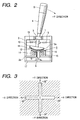
- FIG. 2 is an explanatory diagram illustrating the operation of an operating lever mounted in the stalk switch.
- FIG. 3 is an explanatory diagram illustrating the range of motion of the operating lever.
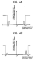
- FIG. 4 is an explanatory diagram illustrating external force applied to the operating lever.
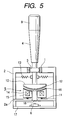
- the turn signal switch comprises a supporting member 2 having a spherical bearing 1, an operating lever 4 having a spherical surface portion supported by the spherical bearing 1, an electromagnetic brake 5 disposed opposite to the lower end of the operating lever 4, an optical image sensor 6 for detecting an operational state of the operating lever 4, an angle sensor 7 for detecting a steering angle of a steering wheel (not shown), and control means 8 for outputting a driving signal c for the electromagnetic brake 5 based on output signals a and b received from the optical image sensor 6 and the angle sensor 7, respectively.
- the spherical surface portion 3 is formed a little to the base of the operating lever and is supported by the spherical bearing 1, so that the operating lever 4 is supported so as to freely rock with respect to the supporting member 2.
- a knob 9 is attached to the front end of the operating lever 4. For example, by rotating the knob 9 around an axis of the operating lever 4, a rotary switch (not shown) is driven to turn on and off headlights. Alternatively, by pressing the knob 9 in the axial direction of the operating lever 4, a push switch (not shown) may be driven to turn on and off headlights.
- an external force receiving portion 10 is formed of a substantially hemispherical shape at the lower end of the operating lever 4 integrally with the operating lever 4, and an armature 12 formed of a magnetic material is formed at the lower end surface 10a of the external power receiving portion 10 with a spring member 11, such as a plate spring, interposed therebetween.
- the lower end surface 10a is formed of a spherical shape whose center is a rocking point (i.e., the spherical surface portion 3) of the operating lever 4, and the armature 12 is also formed of a spherical shape corresponding to the shape of the lower end surface 10a of the operating lever 4.
- a plurality of springs 13 extends between the supporting member 2 and the operating lever 4 on the lower side of the spherical surface portion 3, so that the operating lever 4 may be automatically returned to its neutral position (where the operating lever 4 is vertically positioned with respect to the supporting member 2) by means of elastic force of the springs 13.
- the electromagnetic brake 5 is an actuator for applying predetermined external force to the operating lever 4.
- the electromagnetic brake 5 includes the armature 12 attached to the external force receiving portion 10 of the operating lever 4, a yoke 14 disposed opposite to the armature 12 and fixed to an attaching plate 2a that is a part of the supporting member 2, and an electromagnetic coil 15 wound around the yoke 14.
- a lining material 16 is attached to the upper surface of the yoke 14, and the upper surface of the yoke 14 and the lining material 16 are also formed of spherical shapes corresponding to that of the lower end surface 10a of the operating lever 4.
- the optical image sensor 6 is mounted on a circuit board 17 integrated with the supporting member 2, and a light source (not shown) is also mounted on the circuit board 17.
- An image guide 18 is provided between the optical image sensor 6 and the armature 12 and is also arranged in a central position of the yoke 14 and the electromagnetic coil 15.
- a predetermined detection pattern is formed on the outer surface of the armature 12.
- the armature 12 is irradiated with light emitted from the light source, and an image of the detection pattern formed on the outer surface of the armature is then guided to the optical image sensor 6 through the image guide 18. Therefore, the amount of movement of the operating lever 4 in the X-Y coordinates, that is, the rocking direction and the rocking amount (i.e., the rocking angle) of the operating lever 4, can be detected.
- the controlling means 8 includes an input unit 81 for inputting the output signal a from the optical image sensor 6 and the output signal b from the angle sensor 7, a storage unit 82 for storing any external force tables, a CPU 83 for reading out from the storage unit 82 control signals corresponding to the output signals a and b input to the input unit 81 and for outputting them, a driver circuit 84 for digital-to-analog converting and amplifying the control signals output from the CPU 83 to generate a driving signal c for the electromagnetic coil 15 of the electromagnetic brake 5 and a driving signal d for an external controller 19, and an output unit 85 for outputting the driving signals c and d.
- the CPU 83 receives the output signal a from the optical image sensor 6 and the output signal b from the angle sensor 7 through the input unit 81, and calculates the rocking direction and the rocking amount of the operating lever 4 based on the output signal a from the optical image sensor 6, and also determines whether the operating lever 4 should be automatically returned to its neutral position based on the output signal b from the angle sensor 7.
- the storage unit 82 stores an external force table corresponding to external force applied from the electromagnetic brake 5 to the operating lever 4. The range of movement of the operating lever 4 is defined by the external force, and a predetermined tactile response is also given to the operating lever 4. That is, in the electromagnetic brake 5, the absorption force of the armature 12 is varied according to the amount of current flowing through the electromagnetic coil 15.
- the +X, -X, +Y, and -Y rocking directions are defined from the neutral position of the operating lever 4, and the rocking angle of the operating lever 4 is defined from +20° to -20° in the +X and -X directions, and the rocking angle of the operating lever 4 is defined from +30° to -30° in the +Y and -Y directions.
- the +X, -X, +Y, and -Y directions represent a right turn operation of the turn signal, a left turn operation of the turn signal, an operation for changing to high beam headlights, and an operation for flash-to-pass of headlights, respectively.
- a predetermined click feeling is given at a position before the rocking range of the operating lever 4 in the +X, -X, +Y, and -Y directions.
- the rocking range to be defined and the click feeling to be given for the operating lever 4 can be controlled by the driving signal c output from the output unit 85 of the controlling means 8 to the electromagnetic coil 15 of the electromagnetic brake 5. That is, when the operating lever 4 is rocked from its neutral position (0°) to the +X and -X directions as shown in FIG.
- the driving signal c having a predetermined current value is supplied to the electromagnetic coil 15 to give the click feeling to the operating lever 4 at the point of time when the operating lever 4 is rocked just before the ⁇ 20° limit, and the maximum value of current of the driving signal c is preferably supplied to the electromagnetic coil 15 to restrict the operation of the operating lever 4 at the point of time when the operating lever 4 is rocked up to the limit of ⁇ 20°.
- the operating lever 4 is rocked from its neutral position (0°) to the ⁇ Y directions as shown in FIG.
- the click feeling is given to the operating lever 4 by supplying the electromagnetic coil 15 with the driving signal c having a predetermined current value at the point of time when the operating lever 4 is rocked just before the ⁇ 30° limit, and the maximum value of current of the driving signal c is preferably supplied to the electromagnetic coil 15 to restrict the operation of the operating lever 4 at the point of time when the operating lever 4 is rocked up to the limit of ⁇ 30°.
- the driving signal c having the maximum value of current is applied to the electromagnetic coil 15. Therefore, the operating lever 4 is restricted to move in the oblique directions.
- the armature 12 attached to the external force receiving portion 10 also rotates in the clockwise direction, so that an image of a detection pattern formed on the outer surface of the armature 12 is guided to the optical image sensor 6 through the image guide 18, and the output signal a from the optical image sensor 6 is input to the input unit 81 of the controlling means 8.
- the CPU 83 calculates the rocking direction and the rocking amount (the rocking angle) of the operating lever 4 based on the output signal a compares the calculated results with the external force table stored in the storage unit 82, and then a predetermined driving signal c is output from the driver circuit 84 to the electromagnetic coil 15 of the electromagnetic brake 5 through the output unit 85.
- the driving signal d is output from the output unit 85 of the controlling means 8 to the controller 19 of an automobile body when the operating lever 4 is locked at the stroke end position of the right direction, so that a turn signal lamp for the right turn is flashed.
- the same procedure can be performed when the operating lever 4 is rocked from its neutral position to the left direction. In this case, a turn signal lamp for the left turn (not shown) is flashed when the operating lever 4 is locked at the stroke end position (20°) of the -X direction.
- the CPU 83 determines whether the operating lever 4 should be automatically returned to its neutral position based on the output signal b from the angle sensor 7. Therefore, as described above, when the steering wheel is rotated in a direction opposite to the rocking direction of the operating lever 4 while the operating lever 4 is locked at the right and left stroke end positions, the driving signal c to be supplied to the electromagnetic coil 15 is cancelled. As a result, the electromagnetic brake 5 that is locking the operating lever 4 at the stroke end position is deactivated, so that the operating lever 4 is automatically returned to its neutral position by means of the elastic force of each spring 13.
- the driving signal d is output from the output unit 85 of the control means 8 to the controller 19 of the automobile body to switch headlights to a high beam mode.
- a small operating force is applied from the electromagnetic brake 5 to the operating lever 4 just before the operating lever 4 is rocked up to the stroke end position (30°) of the -Y direction, which is then recognized as a click feeling by the operator who is holding the operating lever 4.
- the driving signal d is output from the output unit 85 of the controlling means 8 to the controller 19 of the automobile body to operate the flash-to-pass operation for the headlights.
- the operating lever 4 since the operating force applied from the electromagnetic brake 5 to the operating lever 4 is small, the operating lever 4 is not locked at the stroke end position of the -Y direction.
- the operating lever 4 is automatically returned to its neutral position by the elastic force of each spring 13 when the operating force in the -Y direction is removed from the operating lever 4.
- the turn signal switch in accordance with the present embodiment comprises the operating lever 4 manually operated by the operator, the supporting member 2 for rockably supporting the operating lever 4, the electromagnetic brake 5 arranged to be opposite to the base end of the operating lever 4, the optical image sensor 6 for detecting the operational state of the operating lever 4, and the controlling means 8 for controlling the drive of the electromagnetic brake 5 based on the output signal a from the optical image sensor 6, wherein the range of movement of the operating lever 4 is defined by the electromagnetic brake 5, and a predetermined tactile response corresponding to the operational state is given to the operating lever 4, so that the range of movement of the operating lever 4 can be set to any values, and a click feeling or the lock maintaining force required for the operating lever 4 can also be set to any values, which results in the turn signal switch having a simplified structure and wide general-purpose applicability.
- the range of movement of the operating lever 4 is defined to be four directions perpendicular to each other.
- the range of movement of the operating lever 4 may be defined to be four directions that are not mutually perpendicular, or may be defined to be other directions, and the operating force applied from the electromagnetic brake 5 to the operating lever 4 or the position thereof may be freely set.
- the lower end surface 10a of the external force receiving portion 10 of the operating lever 4 is formed of a spherical shape whose center is a rocking point (the spherical portion 3) of the operating lever 4, and the armature 12, which is a component of the electromagnetic brake 5, is attached to the lower end surface 10a with the spring member 11 provided therebetween.
- the upper end surface of the yoke 14 wound with the electromagnetic coil 15 is arranged to be opposite to the armature 12, and the upper end surface of the yoke 14 is formed of a spherical shape corresponding to the shape of the lower end surface 10a.
- the armature 12 when a voltage is applied to the electromagnetic coil 15, the armature 12 can be securely absorbed to the yoke, and when a voltage is not applied to the electromagnetic coil 15, it is possible to securely separate the armature 12 from the yoke 14 by means of the elastic force of the spring member 11. Furthermore, since the lining material 16 is attached to the upper end surface of the yoke 14, the armature 12 can be absorbed to the yoke 14 through the lining material 16 and the brake force of the electromagnetic brake 5 can be stabilized.
- the optical image sensor 6 is used as detection means for detecting the operational state of the operating lever 4, the armature 12 is irradiated with light emitted from the light source, and an image of a detection pattern formed on the outer surface of the armature 12 is guided to the optical image sensor 6 through the image guide 18. Therefore, the structure of the detection means can be securely simplified. Furthermore, since the image guide 18 is arranged at the central positions of the yoke 14 and the electromagnetic coil 15, it is possible to simplify the structure of the detection means.
- the operating lever 4 since the operating lever 4 is automatically return to its neutral position by means of the spring 13, the operating lever 4 can be securely returned to its neutral position by the elastic force of the spring 13 when the operator takes his hand off the operating lever 4.
- the output signal b from the angle sensor 7, which is a steering angle signal of the steering wheel, is input to the control means 8, and the action of the electromagnetic brake 5 is controlled based on the output signal b and the output signal a from the optical image sensor 6.
- the operating lever 4 can be automatically returned to its neutral position by the elastic force of the spring 13, and a cancel mechanism can be added to the turn signal switch.
- the armature 12 which is a component of the electromagnetic brake 5 is attached to the lower end surface 10a of the operating lever 4 through the spring member 11, and the yoke 14 wound with the electromagnetic coil 15 is fixed on the mounting plate 2a integrated with the supporting member 2.
- the armature 12 may be directly attached to the lower end surface 10a of the operating lever 4, and the yoke 14 wound with the electromagnetic coil 15 may be attached on a setting member, such as the mounting plate 2a, through the spring member 11.
- the stalk switch of the present invention is applied to the turn signal switch.
- the present invention may be applied to a stalk switch for operating windshield wipers or a washing solution.
- the present invention is implemented according to the above-mentioned embodiments and has the following effects.
- the actuator is driven based on an output signal from detection means corresponding to the operational state of the operating lever, the range of movement of the operating lever is defined by the actuator, and a predetermined tactile response corresponding to the operational state is given to the operating lever.
- the range of movement of the operating lever can be set to any values by the same actuator, and a click feeling or the lock maintaining force required for the operating lever 4 can also be set to any values. Therefore, the stalk switch can have a simplified structure and wide general-purpose applicability.
Landscapes
- Engineering & Computer Science (AREA)
- Signal Processing (AREA)
- Mechanical Engineering (AREA)
- Physics & Mathematics (AREA)
- General Physics & Mathematics (AREA)
- Automation & Control Theory (AREA)
- Computer Networks & Wireless Communication (AREA)
- Switches With Compound Operations (AREA)
- Mechanical Control Devices (AREA)
- Position Input By Displaying (AREA)
Abstract
Description
Claims (8)
- A stalk switch, comprising:wherein the range of movement of the operating lever is defined by the actuator, and a predetermined tactile response corresponding to the operational state is given to the operating lever.an operating lever manually operated by an operator;a supporting member for rockably supporting the operating lever;an actuator arranged opposite to a base end of the operating lever;detecting means for detecting an operational state of the operating lever; andcontrolling means for controlling the drive of the actuator based on an output signal from the detecting means,
- The stalk switch according to Claim 1,
wherein the actuator comprises an electromagnetic brake having an armature and an electromagnetic coil, and
wherein the armature is attached to the base end of the operating lever through a spring member, and an end surface of a yoke wound with the electromagnetic coil is opposite to the armature. - The stalk switch according to Claim 2,
wherein the actuator comprises the electromagnetic brake having the armature attached to the base end of the operating lever and the yoke wound with the electromagnetic coil, and
wherein the end surface of the yoke is opposite to the armature, and the yoke is attached to a setting member through a spring member. - The stalk switch according to Claim 2 or 3,
wherein the armature is formed of a spherical shape whose center is a rocking point of the operating lever, and the end surface of the yoke is formed of the same shape as that of the armature. - The stalk switch according to any one of Claim 2 to 4,
wherein an optical image sensor is used as the detecting means, and
wherein light emitted from a light source is reflected from the armature and is incident on the optical image sensor to detect the operational state of the operating lever. - The stalk switch according to Claim 5,
wherein an image guide is provided between the armature and the optical image sensor and is arranged at the center of the electromagnetic coil. - The stalk switch according to any one of Claims 1 to 6,
wherein an elastic member is provided for automatically returning the operating lever to its neutral position that is set in the supporting member. - The stalk switch according to any of Claims 1-7,
wherein a steering angle signal is input to the controlling means, and the controlling means controls the drive of the actuator based on the steering angle signal and the output signal from the detecting means.
Applications Claiming Priority (2)
| Application Number | Priority Date | Filing Date | Title |
|---|---|---|---|
| JP2003115771 | 2003-04-21 | ||
| JP2003115771A JP2004326163A (en) | 2003-04-21 | 2003-04-21 | Stoking switch |
Publications (3)
| Publication Number | Publication Date |
|---|---|
| EP1471551A2 true EP1471551A2 (en) | 2004-10-27 |
| EP1471551A3 EP1471551A3 (en) | 2005-09-14 |
| EP1471551B1 EP1471551B1 (en) | 2007-01-10 |
Family
ID=32959580
Family Applications (1)
| Application Number | Title | Priority Date | Filing Date |
|---|---|---|---|
| EP04009031A Expired - Lifetime EP1471551B1 (en) | 2003-04-21 | 2004-04-15 | Stalk switch |
Country Status (6)
| Country | Link |
|---|---|
| US (1) | US7019238B2 (en) |
| EP (1) | EP1471551B1 (en) |
| JP (1) | JP2004326163A (en) |
| KR (1) | KR100579610B1 (en) |
| CN (1) | CN1285984C (en) |
| DE (1) | DE602004004191T2 (en) |
Cited By (5)
| Publication number | Priority date | Publication date | Assignee | Title |
|---|---|---|---|---|
| EP1865525A1 (en) | 2006-06-09 | 2007-12-12 | Kabushiki Kaisha Tokai-Rika-Denki-Seisakusho | Switch device |
| DE102006061121A1 (en) * | 2006-12-22 | 2008-06-26 | Preh Gmbh | Electric switch especially for motor vehicle, has switching element which operates in conjunction with circuit board arranged on housing of switch |
| EP2081098A3 (en) * | 2008-01-18 | 2010-01-20 | Honeywell International Inc. | Apparatus for releasably securing a rotatable object in a predetermined position |
| EP3007194A1 (en) * | 2014-10-08 | 2016-04-13 | limoss GmbH & Co. KG | Manual lever switch |
| EP3412490A1 (en) * | 2017-06-09 | 2018-12-12 | Valeo Schalter und Sensoren GmbH | Operating device for operating of at least one device in a motor vehicle, with an operating element and with a switchgear with a sliding element, motor vehicle and method |
Families Citing this family (52)
| Publication number | Priority date | Publication date | Assignee | Title |
|---|---|---|---|---|
| US20040040800A1 (en) | 2002-07-31 | 2004-03-04 | George Anastas | System and method for providing passive haptic feedback |
| US7198137B2 (en) * | 2004-07-29 | 2007-04-03 | Immersion Corporation | Systems and methods for providing haptic feedback with position sensing |
| US8441433B2 (en) | 2004-08-11 | 2013-05-14 | Immersion Corporation | Systems and methods for providing friction in a haptic feedback device |
| US8803796B2 (en) * | 2004-08-26 | 2014-08-12 | Immersion Corporation | Products and processes for providing haptic feedback in a user interface |
| US8002089B2 (en) | 2004-09-10 | 2011-08-23 | Immersion Corporation | Systems and methods for providing a haptic device |
| US7764268B2 (en) | 2004-09-24 | 2010-07-27 | Immersion Corporation | Systems and methods for providing a haptic device |
| KR101047663B1 (en) * | 2004-12-14 | 2011-07-08 | 현대자동차주식회사 | Combination switch structure and control method of vehicle |
| GB0526062D0 (en) * | 2005-12-22 | 2006-02-01 | Penny & Giles Controls Ltd | Joystick controller |
| FR2896082B1 (en) * | 2006-01-10 | 2012-10-26 | Bosch Rexroth Dsi Sas | REMOTE CONTROL OF PUBLIC WORKS MACHINE |
| DE102007018891B4 (en) | 2006-05-03 | 2018-07-05 | Marquardt Gmbh | switching device |
| US7767916B2 (en) * | 2006-06-30 | 2010-08-03 | Kabushiki Kaisha Tokai Rika Denki Seisakusho | Switch device |
| KR101163813B1 (en) * | 2006-11-24 | 2012-07-09 | 현대자동차주식회사 | Multi function switch and controlling apparatus for operating power using the same |
| US7804036B2 (en) * | 2007-02-20 | 2010-09-28 | Kabushiki Kaisha Tokai Rika Denki Seisakusho | Control switch apparatus |
| KR100817331B1 (en) | 2007-02-20 | 2008-03-27 | 대성전기공업 주식회사 | Direction switch and direction switch device |
| US9218059B2 (en) | 2007-08-24 | 2015-12-22 | Denso Corporation | Input apparatus for vehicle |
| JP5300326B2 (en) * | 2007-08-24 | 2013-09-25 | 株式会社デンソー | In-vehicle input device |
| KR200445703Y1 (en) * | 2007-09-03 | 2009-08-26 | 대성전기공업 주식회사 | Self Return Lever Switch Unit |
| KR100941586B1 (en) | 2008-02-21 | 2010-02-11 | 대성전기공업 주식회사 | Automotive Combination Switches |
| JP2010176317A (en) * | 2009-01-28 | 2010-08-12 | Tokai Rika Co Ltd | Input device |
| US9568939B2 (en) | 2009-06-01 | 2017-02-14 | Enovation Controls, Llc | Tactile feedback for joystick position/speed controls |
| US20100302017A1 (en) * | 2009-06-01 | 2010-12-02 | Econtrols, Inc. | Tactile Feedback for Joystick Position/Speed Controls |
| US8392023B2 (en) * | 2009-11-30 | 2013-03-05 | GM Global Technology Operations LLC | Photo-interrupter based force sensing handle and method of use |
| JP5471393B2 (en) * | 2009-12-11 | 2014-04-16 | 株式会社日本自動車部品総合研究所 | Input device |
| US8543298B2 (en) * | 2011-06-03 | 2013-09-24 | Caterpillar Inc. | Operator interface with tactile feedback |
| JP6016273B2 (en) * | 2013-06-25 | 2016-10-26 | アルプス電気株式会社 | Rotary actuator and operation feeling imparting type input device using the same |
| JP6117026B2 (en) * | 2013-07-04 | 2017-04-19 | アルプス電気株式会社 | Operation lever device |
| DE102013215201A1 (en) * | 2013-08-02 | 2015-02-05 | Ford Global Technologies, Llc | Turn signal switch and method for resetting a turn signal switch |
| DE102014103988A1 (en) | 2014-03-24 | 2015-09-24 | Elobau Gmbh & Co. Kg | Joystick with intrinsically safe force feedback |
| US9393901B2 (en) * | 2014-07-21 | 2016-07-19 | Kostal Of America | Turn signal systems and methods |
| DE102014114111A1 (en) * | 2014-09-29 | 2016-03-31 | Werma Holding Gmbh + Co. Kg | Optical signal device |
| US9718405B1 (en) | 2015-03-23 | 2017-08-01 | Rosco, Inc. | Collision avoidance and/or pedestrian detection system |
| CN110073308B (en) * | 2016-12-14 | 2020-09-15 | 阿尔卑斯阿尔派株式会社 | operating device |
| CN107193321B (en) * | 2017-05-25 | 2018-10-12 | 中国铁道科学研究院 | Handle type position control based on image recognition |
| CN107510945B (en) * | 2017-09-05 | 2023-06-30 | 深圳市道通智能航空技术股份有限公司 | Rocker device and remote controller with the rocker device |
| KR102024462B1 (en) * | 2018-03-12 | 2019-09-23 | 경희대학교 산학협력단 | Operation lever for vehicle |
| JP7022913B2 (en) * | 2018-04-19 | 2022-02-21 | パナソニックIpマネジメント株式会社 | Lever input device |
| US10941541B2 (en) * | 2018-07-26 | 2021-03-09 | The Charles Machine Works, Inc. | Cruise control on a work machine |
| DE102018219538A1 (en) * | 2018-11-15 | 2019-09-19 | Audi Ag | Operating device with a traceable to a rest position control element, control device, method for operating the operating device, and motor vehicle |
| DE102018219540A1 (en) | 2018-11-15 | 2020-05-20 | Audi Ag | Control device with an electromagnetic retaining element, and motor vehicle |
| CN113196200B (en) * | 2018-12-21 | 2022-12-09 | 阿尔卑斯阿尔派株式会社 | operating device |
| SG11202106477SA (en) * | 2019-01-31 | 2021-07-29 | Razer Asia Pacific Pte Ltd | Inductive joystick |
| JP7145106B2 (en) * | 2019-03-07 | 2022-09-30 | 東洋電装株式会社 | Auto-cancellation mechanism of turn signal switch device |
| DE102020102995B3 (en) * | 2020-02-06 | 2021-03-04 | Audi Aktiengesellschaft | STEERING COLUMN SWITCH AND METHOD OF CONTROLLING AN ELECTROMAGNET IN A STEERING COLUMN SWITCH |
| JP7484338B2 (en) * | 2020-03-31 | 2024-05-16 | スズキ株式会社 | Electric vehicle operation device |
| CN112109689B (en) * | 2020-09-30 | 2024-11-19 | 浙江万安科技股份有限公司 | Manual valve assembly |
| CN214175914U (en) * | 2020-10-28 | 2021-09-10 | 瑞声科技(新加坡)有限公司 | Combined switch |
| US12115916B2 (en) | 2021-02-01 | 2024-10-15 | Rosco, Inc. | Downlighting signal and illumination mirror head for vehicle |
| CN113389437B (en) * | 2021-07-16 | 2022-05-24 | 贵州华阳电工有限公司 | Electromagnetic unlocking button switch |
| EP4260792A1 (en) * | 2022-04-15 | 2023-10-18 | Huvitz Co., Ltd. | Controller and eye-examining device having the same |
| US20250319391A1 (en) * | 2022-05-27 | 2025-10-16 | Sony Interactive Entertainment Inc. | Controller device |
| US20250352890A1 (en) * | 2022-06-14 | 2025-11-20 | Sony Interactive Entertainment Inc. | Operating device, method for controlling operating device, information processing apparatus, and program |
| DE102023104234A1 (en) * | 2023-02-21 | 2024-08-22 | Valeo Schalter Und Sensoren Gmbh | Vehicle operating device with an operating element and an actuating force changing device, and method |
Family Cites Families (32)
| Publication number | Priority date | Publication date | Assignee | Title |
|---|---|---|---|---|
| US3312917A (en) * | 1965-12-01 | 1967-04-04 | Garcia Uville Alexander | Electrical control switch for automobile air conditioners |
| DE2931489C2 (en) * | 1979-08-03 | 1987-07-09 | Jungheinrich Unternehmensverwaltung Kg, 2000 Hamburg | Control lever switch |
| US4333071A (en) * | 1980-08-07 | 1982-06-01 | Hiroshi Kira | Self-cancelling apparatus for vehicle turn indicators |
| US4473725A (en) * | 1982-10-26 | 1984-09-25 | Wico Corporation | Modular joystick controller |
| US4459440A (en) * | 1983-03-21 | 1984-07-10 | Wico Corporation | Joystick and switch assembly therefor |
| US4733214A (en) * | 1983-05-23 | 1988-03-22 | Andresen Herman J | Multi-directional controller having resiliently biased cam and cam follower for tactile feedback |
| US4721834A (en) * | 1986-04-30 | 1988-01-26 | Emhart Industries, Inc. | Lever control system |
| JPH06101672B2 (en) * | 1990-01-19 | 1994-12-12 | 株式会社東芝 | Voltage comparison circuit |
| JP3206937B2 (en) * | 1991-07-31 | 2001-09-10 | 株式会社ニデック | Joystick mechanism for ophthalmic equipment |
| JP2519868Y2 (en) * | 1992-02-04 | 1996-12-11 | 小倉クラッチ株式会社 | Exciter |
| JPH0683469A (en) * | 1992-08-29 | 1994-03-25 | Namco Ltd | Operating lever device |
| JPH06187093A (en) * | 1992-12-15 | 1994-07-08 | Asahi Optical Co Ltd | Input device |
| US5721566A (en) * | 1995-01-18 | 1998-02-24 | Immersion Human Interface Corp. | Method and apparatus for providing damping force feedback |
| US5555004A (en) * | 1993-08-30 | 1996-09-10 | Hosiden Corporation | Input control device |
| US6850222B1 (en) * | 1995-01-18 | 2005-02-01 | Immersion Corporation | Passive force feedback for computer interface devices |
| WO1996038810A1 (en) * | 1995-06-02 | 1996-12-05 | Gerhard Wergen | Analogue control element |
| US5691898A (en) * | 1995-09-27 | 1997-11-25 | Immersion Human Interface Corp. | Safe and low cost computer peripherals with force feedback for consumer applications |
| DE19651315A1 (en) * | 1996-12-11 | 1998-06-18 | A B Elektronik Gmbh | Rotary indexing switch with latched dialling settings e.g. for dialling motor vehicle on-board computer |
| US6320487B1 (en) * | 1997-03-25 | 2001-11-20 | Lear Automotive Dearborn, Inc. | Control device with tailored feedback |
| JPH11303905A (en) * | 1998-02-18 | 1999-11-02 | Hitachi Ltd | Electromagnetic brake device |
| JP2000195370A (en) * | 1998-12-28 | 2000-07-14 | Sony Computer Entertainment Inc | Reaction force generator |
| US6353430B2 (en) * | 1999-03-23 | 2002-03-05 | Cts Corporation | Gimbal mounted joy stick with z-axis switch |
| DE19926576C2 (en) * | 1999-06-11 | 2002-09-26 | Kostal Leopold Gmbh & Co Kg | Operating device for manual input of control signals to a control unit |
| JP3896734B2 (en) * | 1999-10-04 | 2007-03-22 | 松下電器産業株式会社 | Multidirectional operation switch and electronic device using the same |
| JP2001143558A (en) * | 1999-11-18 | 2001-05-25 | Alps Electric Co Ltd | Stalk switch |
| JP2002062944A (en) * | 2000-08-18 | 2002-02-28 | Alps Electric Co Ltd | On-vehicle input device |
| JP2002196883A (en) * | 2000-12-22 | 2002-07-12 | Alps Electric Co Ltd | Manual input device and on-vehicle equipment controller using the manual input device |
| EP1217496B1 (en) * | 2000-12-22 | 2008-11-19 | Alps Electric Co., Ltd. | Manual input device which provides its control knob with plural modes of operation feeling, and car-mounted apparatus controller based thereon |
| JP2002260495A (en) * | 2001-03-05 | 2002-09-13 | Alps Electric Co Ltd | Magnetic stalk switch |
| US6624364B2 (en) * | 2001-07-25 | 2003-09-23 | Lear Automotive Dearborn, Inc. | Multifunction stalk-mounted switch |
| US6844510B2 (en) * | 2002-08-09 | 2005-01-18 | Stonebridge Control Devices, Inc. | Stalk switch |
| US6803532B1 (en) * | 2004-03-19 | 2004-10-12 | Kyea Kwang Lee | Multi-positional switch for aircraft |
-
2003
- 2003-04-21 JP JP2003115771A patent/JP2004326163A/en not_active Withdrawn
-
2004
- 2004-04-15 EP EP04009031A patent/EP1471551B1/en not_active Expired - Lifetime
- 2004-04-15 DE DE602004004191T patent/DE602004004191T2/en not_active Expired - Fee Related
- 2004-04-20 KR KR1020040027122A patent/KR100579610B1/en not_active Expired - Fee Related
- 2004-04-20 CN CNB2004100369718A patent/CN1285984C/en not_active Expired - Fee Related
- 2004-04-20 US US10/827,808 patent/US7019238B2/en not_active Expired - Fee Related
Cited By (8)
| Publication number | Priority date | Publication date | Assignee | Title |
|---|---|---|---|---|
| EP1865525A1 (en) | 2006-06-09 | 2007-12-12 | Kabushiki Kaisha Tokai-Rika-Denki-Seisakusho | Switch device |
| US7714242B2 (en) | 2006-06-09 | 2010-05-11 | Kabushiki Kaisha Tokai Rika Denki Seisakusho | Switch device |
| DE102006061121A1 (en) * | 2006-12-22 | 2008-06-26 | Preh Gmbh | Electric switch especially for motor vehicle, has switching element which operates in conjunction with circuit board arranged on housing of switch |
| DE102006061121B4 (en) * | 2006-12-22 | 2009-11-26 | Preh Gmbh | Electric switch for a motor vehicle |
| EP2081098A3 (en) * | 2008-01-18 | 2010-01-20 | Honeywell International Inc. | Apparatus for releasably securing a rotatable object in a predetermined position |
| US7866230B2 (en) | 2008-01-18 | 2011-01-11 | Honeywell International Inc. | Apparatus for releasably securing a rotatable object in a predetermined position |
| EP3007194A1 (en) * | 2014-10-08 | 2016-04-13 | limoss GmbH & Co. KG | Manual lever switch |
| EP3412490A1 (en) * | 2017-06-09 | 2018-12-12 | Valeo Schalter und Sensoren GmbH | Operating device for operating of at least one device in a motor vehicle, with an operating element and with a switchgear with a sliding element, motor vehicle and method |
Also Published As
| Publication number | Publication date |
|---|---|
| DE602004004191D1 (en) | 2007-02-22 |
| CN1551270A (en) | 2004-12-01 |
| US7019238B2 (en) | 2006-03-28 |
| US20040206611A1 (en) | 2004-10-21 |
| KR20040091569A (en) | 2004-10-28 |
| KR100579610B1 (en) | 2006-05-12 |
| DE602004004191T2 (en) | 2007-10-25 |
| CN1285984C (en) | 2006-11-22 |
| EP1471551A3 (en) | 2005-09-14 |
| EP1471551B1 (en) | 2007-01-10 |
| JP2004326163A (en) | 2004-11-18 |
Similar Documents
| Publication | Publication Date | Title |
|---|---|---|
| US7019238B2 (en) | Stalk switch | |
| US7176892B2 (en) | Lever handle type haptic input apparatus equipped with electromagnetic brake | |
| JP4614347B2 (en) | Vehicle lamp | |
| CN100459005C (en) | Rotary switch in automobile | |
| RU2218284C2 (en) | Multifunctional change-over switch | |
| US20050141234A1 (en) | Vehicle lighting apparatus | |
| JP3972612B2 (en) | Compound switch | |
| KR20010023047A (en) | Manoeuvring device | |
| JPH0950735A (en) | Cancel mechanism of turn signal switch for vehicle | |
| JP4400884B2 (en) | Vehicle lamp | |
| US10988076B2 (en) | Steering column control module | |
| JPH1050178A (en) | Multi-directional actuation switch | |
| EP1760742B1 (en) | Switch device and steering switch apparatus equipped with the switch device | |
| WO2016098436A1 (en) | Turn signal operation device | |
| US10703258B2 (en) | Transmission mechanism, lever mechanism, and contactless lever switch | |
| JP2512319B2 (en) | Vehicle headlamp tilting device | |
| KR20250149712A (en) | Steering column switch for automobiles | |
| US4376878A (en) | Switch assembly for use in vehicle | |
| JPH11162299A (en) | Multi-functional operation element | |
| JP4518496B2 (en) | Vehicle lamp | |
| KR920001712B1 (en) | Automotive headlight device | |
| JP2684052B2 (en) | Method and device for controlling headlight irradiation direction of motorcycle | |
| JP4518497B2 (en) | Vehicle lamp | |
| JPH0627477Y2 (en) | Illumination angle adjustment device for vehicle headlights | |
| EP1236614A2 (en) | Headlamp for vehicle |
Legal Events
| Date | Code | Title | Description |
|---|---|---|---|
| PUAI | Public reference made under article 153(3) epc to a published international application that has entered the european phase |
Free format text: ORIGINAL CODE: 0009012 |
|
| AK | Designated contracting states |
Kind code of ref document: A2 Designated state(s): AT BE BG CH CY CZ DE DK EE ES FI FR GB GR HU IE IT LI LU MC NL PL PT RO SE SI SK TR |
|
| AX | Request for extension of the european patent |
Extension state: AL HR LT LV MK |
|
| PUAL | Search report despatched |
Free format text: ORIGINAL CODE: 0009013 |
|
| AK | Designated contracting states |
Kind code of ref document: A3 Designated state(s): AT BE BG CH CY CZ DE DK EE ES FI FR GB GR HU IE IT LI LU MC NL PL PT RO SE SI SK TR |
|
| AX | Request for extension of the european patent |
Extension state: AL HR LT LV MK |
|
| RIC1 | Information provided on ipc code assigned before grant |
Ipc: 7H 01H 25/04 A Ipc: 7G 05G 5/03 B |
|
| 17P | Request for examination filed |
Effective date: 20051021 |
|
| GRAP | Despatch of communication of intention to grant a patent |
Free format text: ORIGINAL CODE: EPIDOSNIGR1 |
|
| AKX | Designation fees paid |
Designated state(s): DE FR GB |
|
| GRAS | Grant fee paid |
Free format text: ORIGINAL CODE: EPIDOSNIGR3 |
|
| GRAA | (expected) grant |
Free format text: ORIGINAL CODE: 0009210 |
|
| AK | Designated contracting states |
Kind code of ref document: B1 Designated state(s): DE FR GB |
|
| REG | Reference to a national code |
Ref country code: GB Ref legal event code: FG4D |
|
| REF | Corresponds to: |
Ref document number: 602004004191 Country of ref document: DE Date of ref document: 20070222 Kind code of ref document: P |
|
| ET | Fr: translation filed | ||
| PLBE | No opposition filed within time limit |
Free format text: ORIGINAL CODE: 0009261 |
|
| STAA | Information on the status of an ep patent application or granted ep patent |
Free format text: STATUS: NO OPPOSITION FILED WITHIN TIME LIMIT |
|
| 26N | No opposition filed |
Effective date: 20071011 |
|
| PGFP | Annual fee paid to national office [announced via postgrant information from national office to epo] |
Ref country code: GB Payment date: 20090312 Year of fee payment: 6 |
|
| PGFP | Annual fee paid to national office [announced via postgrant information from national office to epo] |
Ref country code: DE Payment date: 20090430 Year of fee payment: 6 Ref country code: FR Payment date: 20090406 Year of fee payment: 6 |
|
| GBPC | Gb: european patent ceased through non-payment of renewal fee |
Effective date: 20100415 |
|
| REG | Reference to a national code |
Ref country code: FR Ref legal event code: ST Effective date: 20101230 |
|
| PG25 | Lapsed in a contracting state [announced via postgrant information from national office to epo] |
Ref country code: DE Free format text: LAPSE BECAUSE OF NON-PAYMENT OF DUE FEES Effective date: 20101103 |
|
| PG25 | Lapsed in a contracting state [announced via postgrant information from national office to epo] |
Ref country code: GB Free format text: LAPSE BECAUSE OF NON-PAYMENT OF DUE FEES Effective date: 20100415 |
|
| PG25 | Lapsed in a contracting state [announced via postgrant information from national office to epo] |
Ref country code: FR Free format text: LAPSE BECAUSE OF NON-PAYMENT OF DUE FEES Effective date: 20100430 |