EP1471364A2 - Methode zur passiven Bestimmung der Position und der Geschwindigkeit einer Quelle, wobei nur Richtungsmessungen verwendet werden und eine Beschleunigung des Beobachters nicht notwendig ist - Google Patents
Methode zur passiven Bestimmung der Position und der Geschwindigkeit einer Quelle, wobei nur Richtungsmessungen verwendet werden und eine Beschleunigung des Beobachters nicht notwendig ist Download PDFInfo
- Publication number
- EP1471364A2 EP1471364A2 EP04252326A EP04252326A EP1471364A2 EP 1471364 A2 EP1471364 A2 EP 1471364A2 EP 04252326 A EP04252326 A EP 04252326A EP 04252326 A EP04252326 A EP 04252326A EP 1471364 A2 EP1471364 A2 EP 1471364A2
- Authority
- EP
- European Patent Office
- Prior art keywords
- emitter
- speed
- range
- platform
- bearing
- Prior art date
- Legal status (The legal status is an assumption and is not a legal conclusion. Google has not performed a legal analysis and makes no representation as to the accuracy of the status listed.)
- Ceased
Links
Images



Classifications
-
- G—PHYSICS
- G01—MEASURING; TESTING
- G01S—RADIO DIRECTION-FINDING; RADIO NAVIGATION; DETERMINING DISTANCE OR VELOCITY BY USE OF RADIO WAVES; LOCATING OR PRESENCE-DETECTING BY USE OF THE REFLECTION OR RERADIATION OF RADIO WAVES; ANALOGOUS ARRANGEMENTS USING OTHER WAVES
- G01S11/00—Systems for determining distance or velocity not using reflection or reradiation
- G01S11/02—Systems for determining distance or velocity not using reflection or reradiation using radio waves
- G01S11/04—Systems for determining distance or velocity not using reflection or reradiation using radio waves using angle measurements
-
- G—PHYSICS
- G01—MEASURING; TESTING
- G01S—RADIO DIRECTION-FINDING; RADIO NAVIGATION; DETERMINING DISTANCE OR VELOCITY BY USE OF RADIO WAVES; LOCATING OR PRESENCE-DETECTING BY USE OF THE REFLECTION OR RERADIATION OF RADIO WAVES; ANALOGOUS ARRANGEMENTS USING OTHER WAVES
- G01S5/00—Position-fixing by co-ordinating two or more direction or position line determinations; Position-fixing by co-ordinating two or more distance determinations
- G01S5/02—Position-fixing by co-ordinating two or more direction or position line determinations; Position-fixing by co-ordinating two or more distance determinations using radio waves
- G01S5/12—Position-fixing by co-ordinating two or more direction or position line determinations; Position-fixing by co-ordinating two or more distance determinations using radio waves by co-ordinating position lines of different shape, e.g. hyperbolic, circular, elliptical or radial
-
- G—PHYSICS
- G01—MEASURING; TESTING
- G01S—RADIO DIRECTION-FINDING; RADIO NAVIGATION; DETERMINING DISTANCE OR VELOCITY BY USE OF RADIO WAVES; LOCATING OR PRESENCE-DETECTING BY USE OF THE REFLECTION OR RERADIATION OF RADIO WAVES; ANALOGOUS ARRANGEMENTS USING OTHER WAVES
- G01S7/00—Details of systems according to groups G01S13/00, G01S15/00, G01S17/00
- G01S7/02—Details of systems according to groups G01S13/00, G01S15/00, G01S17/00 of systems according to group G01S13/00
- G01S7/021—Auxiliary means for detecting or identifying radar signals or the like, e.g. radar jamming signals
Definitions
- the present invention relates generally to Electronic Surveillance Measures (ESM) intercept receivers, and more particularly, to a method for passively estimating an emitter's position and velocity using bearings-only without requiring observer acceleration.
- ESM Electronic Surveillance Measures
- ESM intercept receivers are used to collect radar data, and in particular, to perform a pulse parameter measurement function.
- Pulse parameter measurements are used to type or "fingerprint" radar systems.
- the measurements include the traditional parameters such as pulse time of arrival (TOA), pulse width (PW), amplitude, and frequency, and also pulse internals, such as modulation, as is known to persons of skill in the art.
- TOA pulse time of arrival
- PW pulse width
- modulation modulation
- ESM systems also typically measure emitter bearing in azimuth and, less commonly, elevation.
- the emitter azimuth or bearing is used to sort the many interleaved pulses from diverse radars obtained in a single wideband receiver dwell. These bearings can also be utilized across several dwells to support a significant additional capability: passive estimation of a moving emitter's range and velocity.
- FIG. 1A illustrates an observer maneuver for an important special case of a constant velocity emitter.
- an observer 100 flies a constant velocity track 101 between a point where a first bearing cut 102 and a last bearing cut 103 was made.
- An infinite number of target tracks could produce a measured azimuth change. Examples of these ambiguous tracks are indicated by reference numerals 104, 105 and 106.
- the target track is said to be "unobservable” (Kalman, Ho and Narenda, "Controllability of Linear Dynamical Systems,” Contributions to Differential Equations, Vol I, McMillan, New York, 1961) .
- obtaining observability in this case requires an observer acceleration, as illustrated in Figure 1B.
- An observer 109 changes heading and flies a new track 107.
- Requiring the observer to maneuver in order to locate a moving emitter is very limiting, especially for aircraft. Since the emitter's range and velocity are not known before the maneuver, performing the maneuver can easily put the observer in an undesirable tactical position relative to the emitting platform. Also such maneuvers require aileron and other control surface deflections, and significant bank angles, which increase the observer's radar cross section. Hence, especially for stealth aircraft, these required turns can be extremely detrimental.
- ESM systems typically extract from pulse measurements of a target. These extracted parameters may allow the ESM system to categorize both the target aircraft type and overall mission. They may also allow determination of the aircraft intent during the pulse collection period. Once target aircraft platform type and intent are known it is possible to bracket target speeds within a very narrow range. Such bracketing is possible because aircraft generally do not travel at arbitrary speeds within their flight envelope. Aircraft optimize speed to match the requirements of their particular mission.
- Examples of typical aircraft missions include surveillance, escort and intercept. These missions involve cruise, loiter, supersonic dash, and missile launch flight regimes. Performance in each of these regimes is determined, for a given altitude, weight and configuration, by the particular aircraft's thrust or power available, P a , and power required P r . As shown in aerodynamics textbooks, e.g. D.P Raymer's "Aircraft Design: A Conceptual Approach, " American Institute of Aeronautics and Astronautics, Washington, DC 1989, P r depends on the lift and drag coefficients C D and C L specific to the aircraft airframe.
- Figure 2 illustrates some of the discrete performance speeds determined from P a and P r curves for a turbojet aircraft type at a fixed altitude and weight. Raymer describes the use of such P a -P r curves in determining best aircraft speed for a given performance requirement.
- jet aircraft performance will be used as examples here, piston and turboprop results are entirely analogous.
- the minimum value at P r 200 gives the speed 203 requiring minimum thrust.
- Intersection of P a and P r 201 gives the speed at which the aircraft stalls, while intersection 202 gives the maximum speed attainable.
- the maximum endurance, or longest time-in-the-air speed is indicated by reference numeral 203, which is also the speed giving the maximum lift-to-drag ratio, i.e.
- the maximum range speed is located at point 204, which is also the speed, at any altitude, weight and configuration, for which C L / C D max is maximum.
- Other discrete speeds such as for best rate-of-climb are similarly determined for a particular aircraft type depending on the aircraft performance curve.
- an object of the present invention is to obtain emitter range and heading from bearing measurements without requiring a constant acceleration, or any other observer maneuver.
- the sequential order is relative heading, and speed as a function of range and, separately, speed from ESM radar identification parameters, then absolute emitter heading and range.
- the present invention overcomes the requirement to maneuver in order to determine bearings-only range by utilizing the fact that aircraft must fly at certain discrete speeds to successfully accomplish their mission, and that these speeds can be determined from ESM parameters derived from the signal.
- both relative heading and speed as a function of range are initially found from bearing measurements.
- the bearings used to generate them can be measured during a constant velocity leg, without requiring the maneuver intrinsic to conventional target motion analysis or TMA.
- a separate discrete speed estimation process also occurs in parallel after platform identification. Once the discrete speed is estimated, range and absolute heading are determined from the continuous speed functional relation.
- a further object of the present invention at least in its preferred embodiments is to derive the discrete emitter speed estimate s est from the radar fingerprinting process rather than the bearing measurements.
- ESM parameters such as pulse width, pulse time-of-arrival, pulse time-of-arrival frame interval and pulse rate interval (PRI) stagger levels, can uniquely determine the radar and its mode of operation. Knowledge of the radar and mode determine the aircraft and aircraft's flight regime. The aircraft's flight regime determines its speed.
- a method of estimating target range and heading from bearing measurements without requiring observer heading change or observer acceleration during the bearing measurement collection period including measuring the emitter signal frequency, time and phase characteristics, generating from these measurements a set of parameters that characterize a specific emitter as a signal source, identifying, based on the emitter characterization and an emitter-platform association data base, a most probable platform the emitter is on and associating the mode of operation of the emitter and the corresponding specific platform with a particular kinematic regime, and utilizing a performance data base to derive based on the kinematic regime a specific speed or discrete set of speeds best adapted to the platform's mission, while also generating from the measured emitter characteristics the emitter bearings, estimating from emitter bearings the emitter speed as a continuous function of emitter range, then determining, by comparing the continuous speed with the discrete speed derived from the platform performance data base, the emitter range consistent therewith, and assign
- the present invention comprises a method of estimating target range and heading from bearing measurements without requiring observer heading change or observer acceleration during the bearing measurement collection period, comprising the steps of:
- the invention provides computer-readable medium including a data structure for an emitter-platform association data base, a data structure for a performance data base, and a sequence of machine executable instructions in machine form.
- the sequence of instructions cause the processor to determine characteristics of a measured emitter signal and generate a set of parameters characterizing a specific emitter as a signal source based on the determined characteristics.
- a most probable platform including the emitter based on the generated parameters and the emitter-platform association data base is identified and the emitter operating mode and corresponding specific platform are associated with a particular kinematic regime.
- the platform performance data base is used to (1) derive based on the kinematic regime one or more speed values best adapted to the platform mission, (2) generate based on the emitter signal measurement the emitter bearing, (3) estimate from the emitter bearing the emitter speed as a continuous function of emitter range, and (4) determine the emitter range consistent therewith by comparing the continuous emitter speed with the one or more speed values derived from the performance data base.
- Equation 2b the quantity range-rate over range, r ⁇ -/r, can be obtained from bearing-change estimates ⁇ ⁇ and , i.e.
- Figure 3a illustrates this test graphically for a simulation for a 480 knot emitter at 80nmi with a 30° relative bearing.
- the observer was flying 420 knots.
- the receiver revisit rate was 100 msec for two seconds.
- the intersection of the estimated target speed 301 with the range-mapped-into-speed-via-bearing-change curve 300 gives the true range 302.
- Equation 1 is in polar coordinates and does not assume observer or emitter accelerations (the right hand sides are 0), both observer and emitter accelerations can be readily incorporated. Also the above analysis holds if elevation and not just azimuth is available, e.g. Equation 1 is generalized to spherical coordinates.
- FIG. 3b is a top level block diagram of the process flow according to an embodiment of the present invention.
- Emitter signal parameters are extracted (step 303) at each receiver dwell. These parameters must always include bearing 304, and additional parameters 305 such as pulse TOA, pulse width and frequency sufficient to identify the emitter platform.
- the identified platform is associated with a most likely speed at step 306 and the bearings are filtered (step 307) to produce estimates of their first and second derivatives with respect to time.
- the bearing rate estimates are then used to generate speed as a continuous function of range at step 308 using the relations shown, for example, in Equations 3, 4, and 5.
- Emitter range and heading is then determined at step 309 by logic comparing the discrete speed output from step 306 and continuous bearing-rate determined speed output from step 308.
- Equation 1 No observer maneuver is required. But, as noted, a similar analysis can be performed incorporating observer accelerations on the right-hand side of Equation 1. Thus, the method is not restricted to constant velocity observer tracks. Furthermore, target accelerations, as well as speeds, may be deduced from ESM data. If so, these acceleration estimates can also be incorporated in Equation 1. Thus, the method is not restricted to a constant velocity target.
- Determining the required target potential speeds in process step 306 is based partially on data equivalent to the emitter airframe's flight envelope.
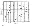
- Figure 4 is an example of such a flight or "operating" envelope depicting the combinations of altitude and speed the aircraft has been designed to withstand.
- Figure 4 depicts the envelope for a typical fighter, consistent with the P a -P r curves in Figure 2.
- the upper portion of the curve 400 is the maximum ceiling, which is determined by the aircraft powerplant's maximum thrust.
- the low speed boundary to the left is limited by the stall and buffet limit.
- the high-speed, high-altitude limit 402 on the right is the result of aerodynamic heating, while the lower portion of the high speed boundary 403 is limited by structural heating and dynamic pressure.
- the jet will operate in only a very narrow region when in a specific mode of operation.
- the aircraft will be at a speed near 204 ( Figure 2) and at an altitude determined by the powerplant's characteristics.
- turbojets produce greater speed for a given amount of thrust, and have lower inlet air temperatures and hence lower fuel consumption at higher altitudes.
- Such considerations determine the specific altitude associated with the P a -P r curve.
- the altitude plus P a -P r curves determine the region 404 ( Figure 4) the jet will be in for cruise operation.
- a speed near point 203 is about 75% slower than the best range speed, and thus the aircraft's speed-altitude pair will fall in region 405. Similar considerations and analyses show that if the aircraft is in supersonic intercept mode it will most likely be in a small, unique altitude-speed region such as 406.
- the region in the flight envelope e.g., specific regions 404, 405 or 406, that the aircraft is operating can be determined from the aircraft radar's mode of operation.
- Typical modes for radar found on intercept aircraft are search, track, illuminate and target.
- Modes found on surveillance type aircraft are search and track.
- AWACS airborne warning and control system
- FIG. 5 depicts a block diagram of a detailed implementation of an embodiment according to the principles of the present invention. Because the derived range depends on the bearing rates of change, a preferred sensor 500 is a short-baseline/long-baseline interferometer (SBI/LBI) as described in Kaplan, United States Patent 4,734,702, "Passive Ranging Method and Apparatus".
- SBI/LBI short-baseline/long-baseline interferometer
- the long baseline interferometer provides excellent bearing resolution, and supports measuring very accurate bearing rates-of-change.
- the SBI should incorporate an elevation array. Elevation measurements help resolve ambiguities in range created by two or more speed estimates from a process 504.
- Process 504 allows for the fact that multiple speeds can occur when the radar identification does not lead to a unique platform identification.
- the ambiguity can be resolved using flight envelope and other altitude dependent data for the candidate platforms. Examples of other altitude dependent data are load factor limits, maximum turn rates, and corner speed. The use of this latter data does not imply the emitting aircraft is maneuvering, but that the altitude may not be consistent with maneuvers required by the flight regime deduced from the radar mode. If the altitude derived from the range estimate and elevation measurement does not give results consistent with the aircraft's immediate mission, the range can be eliminated.
- Process step 501 involves conventional ESM parameter extraction.
- the SBI phase measurement ambiguities are resolved, and bearing and possibly elevation estimates (step 503) derived therefrom.
- the derived estimates are used to resolve the LBI utilizing the method described by Kaplan.
- the bearing and, if measured, elevation estimates are input to step 502 to estimate the first and second derivatives with respect to time.
- process step 501 Before process step 503 estimates the angles, process step 501 must separate or deinterleave and cluster the pulses for each radar detected in the receiver dwell. Once the pulses are clustered, pulse width and other radar discriminants can be measured, as well as signal direction-of-arrival (DOA). If DOA is used as a pulse sorting aid rather than derived in step 503 after deinterleaving, the number of receiver channels must support monopulse phase measurements.
- DOA signal direction-of-arrival
- a particularly important parameter extracted from pulse time-of-arrival measurements is the greatest common divisor of all the interpulse time intervals. This time difference is extremely useful in process step 504, which corresponds to step 306 ( Figure 3b) and in particular in step 505 extracting the radar's identifier (ID). Therefore, it is desirable that the deinterleaver have the capabilities of the Litton Industries Advanced Division's deinterleaver developed for the AN/ALQ-99 jamming system, which extracts the divisor quantity from the pulse TOA measurements as part of the pulse deinterleaving process.
- process step 504 includes the steps of identifying the radar (step 505), and determining the platform (step 506) based on the radar type. Identifying the radar is a well established ESM function. Carrier frequency measurement alone is not especially useful in the identification process, but carrier frequency may be combined with TOA measurements, and in particular greatest common divisor estimates, according to the inventor's United States Patent 5,534,866, entitled “Emitter Frequency-Time Measurement by a Moving Observer Using No Navigation Input" to obtain additional parameters unique to a given radar. Such time-frequency parameters can be very useful in determining not only the radar, but also the particular mode of operation. Thus, in process step 505 the radar mode is also determined, e.g. search or illuminate.
- the radar mode and platform capabilities determine the platform mission, and hence the flight mode, e.g., loiter, cruise or intercept. This correlation between mission and flight mode during the pulse collection period is performed in process step 507. Thus, the mission determines which region 508 in the flight envelope 509 the identified aircraft platform is operating.
- the flight envelope data 509 is specific to each platform. Therefore, the database must encompass all platforms of importance to the observer, e.g. reference numeral 511 represents the flight envelope data base. Thus, process step 507 determines not just the operating region, but the appropriate data set.
- the speed boundary 512 given by the flight envelope data 509 may be broad, e.g. 15% possible speed variation or more.
- the speed is further bounded by refining the estimate using progressively more restrictive performance data.
- This refinement is indicated by the power curves 510, corresponding to Figure 2.
- the power curves 510 For the same platform, there are a set of curves 513, each corresponding to a different altitude and aircraft weight or configuration.
- these and other independent variables must be determined by establishing the region 508 and platform type in process step 507.
- the power-available power-required functions have been emphasized, there are many other performance determinants, such as load factor and turn rate that depend on speed and altitude. Also pilots may fly certain preferred speeds to simplify time-distance calculations. All such data for a given platform is used to systematically refine the speed estimate to a 5% or less variation range.
- the preferred method for obtaining the speed-altitude bounds from radar mode and platform ID, and then progressively narrowing the speed bound is to use rules based on fuzzy expert system theory (R. Kruse, J. Gebhardt, and F. Klawonn, Foundations of Fuzzy Systems, John Wiley and Sons, New York 1994).
- a fuzzy expert system is an expert system that uses a collection of fuzzy membership functions and rules, instead of Boolean logic, to reason about data. Under fuzzy logic more than one inference is possible. Hence, more than one speed and altitude region 508 may be output to the specific performance refinement 510.
- a unique speed 514 is determined in the above processing. This speed in turn gives a unique range estimate 516 using the method described previously.
- the continuous speed curve in 515 i.e. 300 in Figure 3b
- the sensitivity to errors in the discrete speed estimate is thus also a function of relative heading. The sensitivity is known from the slope of the curve, and thus can be used to predict possible error in the range estimate.
- the continuous speed function is generated from the relative heading vector.
- the relative heading vector is found (step 518) directly from the bearing and bearing rates with range as a parameter.
- Emitter velocities consistent with the bearings and bearing rates are then generated in step 519. This requires the observer's velocity vector from the navigation system 517.
- the emitter velocities are thus also parameterized by range.
- the continuous speed function e.g. curve 300 ( Figure 3), is the magnitude of this velocity.
- the method of the present invention does not require the observer to make a heading change or other acceleration during the bearing collection period, but it does not restrict the observer's motion either.
- the navigation (NAV) system 517 measures observer accelerations, these are, effectively, incorporated into the right hand side of Equation 1.
- the platform and mission identification process may indicate the emitter is likely to be maneuvering.
- Such possible observer accelerations are readily incorporated into the above kinematic analysis.
- more than one speed estimate generally results. If the fuzzy logic generates several speed-altitude pairs, the ambiguity can be resolved if elevation measurements are available.
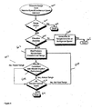
- Figure 6 shows the method for resolving speed-altitude ambiguities.
- range is generated from a discrete speed/continuous speed intersect.
- a unique range determination is performed. If the range is not unique, then the process is complete at step 602. If the range is not unique, then at step 603 an available elevation determination is performed.. If the elevation is not available, then at step 604, all ranges are determined from set of ambiguous speed and the process is complete at step 605.
- the elevation measurement and range estimate are used to determine the platform altitude. The platform altitude is compared with the altitudes consistent with step 508, found from the flight performance data base. If the altitude regions do not overlap based on the determination performed in step 608, the range estimate is rejected at step 607 and the next candidate range 609 is tested until the set of ambiguous range is exhausted.
- the method may be implemented in a highly specialized way used against only a small subset of critical platforms, possibly with their radar operating only in certain restricted modes. Such limited application greatly reduces the data base and simplifies the logic implementation.
Landscapes
- Engineering & Computer Science (AREA)
- Radar, Positioning & Navigation (AREA)
- Remote Sensing (AREA)
- Physics & Mathematics (AREA)
- General Physics & Mathematics (AREA)
- Computer Networks & Wireless Communication (AREA)
- Radar Systems Or Details Thereof (AREA)
- Testing Of Devices, Machine Parts, Or Other Structures Thereof (AREA)
Applications Claiming Priority (2)
| Application Number | Priority Date | Filing Date | Title |
|---|---|---|---|
| US419193 | 1989-10-10 | ||
| US10/419,193 US6714155B1 (en) | 2003-04-21 | 2003-04-21 | Method of passively estimating an emitter's position and velocity using bearings-only without requiring observer acceleration |
Publications (2)
| Publication Number | Publication Date |
|---|---|
| EP1471364A2 true EP1471364A2 (de) | 2004-10-27 |
| EP1471364A3 EP1471364A3 (de) | 2006-03-29 |
Family
ID=31994320
Family Applications (1)
| Application Number | Title | Priority Date | Filing Date |
|---|---|---|---|
| EP04252326A Ceased EP1471364A3 (de) | 2003-04-21 | 2004-04-21 | Methode zur passiven Bestimmung der Position und der Geschwindigkeit einer Quelle, wobei nur Richtungsmessungen verwendet werden und eine Beschleunigung des Beobachters nicht notwendig ist |
Country Status (2)
| Country | Link |
|---|---|
| US (1) | US6714155B1 (de) |
| EP (1) | EP1471364A3 (de) |
Cited By (21)
| Publication number | Priority date | Publication date | Assignee | Title |
|---|---|---|---|---|
| RU2278395C1 (ru) * | 2004-11-29 | 2006-06-20 | Александр Викторович Дубровин | Способ определения координат источников радиоизлучений |
| RU2305851C2 (ru) * | 2005-07-18 | 2007-09-10 | Федеральное государственное унитарное предприятие "Государственный научно-исследовательский институт авиационных систем" | Способ определения координат источника радиоизлучения |
| RU2308735C1 (ru) * | 2006-03-10 | 2007-10-20 | Федеральное государственное учреждение "Федеральный государственный научно-исследовательский испытательный центр радиоэлектронной борьбы и оценки эффективности снижения заметности" Министерства обороны Российской Федерации | Способ определения местоположения источников радиоизлучения в ближней зоне |
| RU2444749C1 (ru) * | 2010-07-26 | 2012-03-10 | Открытое акционерное общество "Конструкторское бюро по радиоконтролю систем управления, навигации и связи" (ОАО "КБ "Связь") | Способ определения дальности до источника радиоизлучения с направленной антенной |
| RU2522170C1 (ru) * | 2013-05-13 | 2014-07-10 | Открытое акционерное общество "Конструкторское бюро по радиоконтролю систем управления, навигации и связи" (ОАО "КБ "Связь") | Способ обнаружения подвижных объектов |
| RU2521608C1 (ru) * | 2013-05-13 | 2014-07-10 | Открытое акционерное общество "Конструкторское бюро по радиоконтролю систем управления, навигации и связи" (ОАО "КБ "Связь") | Способ скрытного обнаружения подвижных объектов |
| RU2524401C1 (ru) * | 2013-05-13 | 2014-07-27 | Открытое акционерное общество "Конструкторское бюро по радиоконтролю систем управления, навигации и связи" (ОАО "КБ "Связь") | Способ обнаружения и пространственной локализации подвижных объектов |
| RU2528391C1 (ru) * | 2013-05-13 | 2014-09-20 | Открытое акционерное общество "Конструкторское бюро по радиоконтролю систем управления, навигации и связи" (ОАО "КБ "Связь") | Способ поиска малозаметных подвижных объектов |
| RU2529483C1 (ru) * | 2013-05-13 | 2014-09-27 | Открытое акционерное общество "Конструкторское бюро по радиоконтролю систем управления, навигации и связи" (ОАО "КБ "Связь") | Способ скрытной радиолокации подвижных объектов |
| RU2534222C1 (ru) * | 2013-05-13 | 2014-11-27 | Открытое акционерное общество "Конструкторсоке бюро по радиоконтролю систем управления, навигации и связи" (ОАО "КБ "Связь") | Способ обнаружения малозаметных подвижных объектов |
| RU2546329C1 (ru) * | 2014-02-14 | 2015-04-10 | Российская Федерация, от имени которой выступает Федеральная служба охраны Российской Федерации (ФСО РФ) | Способ поляризационно-чувствительного обнаружения подвижных объектов |
| RU2546330C1 (ru) * | 2014-02-14 | 2015-04-10 | Российская Федерация, от имени которой выступает Федеральная служба охраны Российской Федерации (ФСО РФ) | Способ поляризационно-чувствительного радиоконтроля подвижных объектов |
| RU2546331C2 (ru) * | 2013-05-13 | 2015-04-10 | Акционерное общество "Конструкторское бюро по радиоконтролю систем управления, навигации и связи" (АО "КБ "Связь") | Способ поиска малоразмерных подвижных объектов |
| RU2557251C1 (ru) * | 2014-02-14 | 2015-07-20 | Российская Федерация, от имени которой выступает Федеральна служба охраны Российской Федерации (ФСО РФ) | Способ поляризационно-чувствительного поиска малоразмерных подвижных объектов |
| RU2557250C1 (ru) * | 2014-02-14 | 2015-07-20 | Российская Федерация, от имени которой выступает Федеральная служба охраны Российской Федерации (ФСО РФ) | Способ скрытной радиолокации подвижных объектов |
| RU2580933C1 (ru) * | 2015-04-13 | 2016-04-10 | Акционерное общество "Конструкторское бюро по радиоконтролю систем управления, навигации и связи" (АО "КБ "Связь") | Способ определения дальности до источника радиоизлучения |
| RU2643154C1 (ru) * | 2016-08-12 | 2018-01-31 | Общество с ограниченной ответственностью "Квадрокс" | Однопозиционный мультипликативный виртуально-реальный способ определения координат местоположения источников радиоизлучения |
| RU2643360C1 (ru) * | 2017-03-27 | 2018-02-01 | Юрий Николаевич Гайчук | Способ определения координат источника радиоизлучения в трехмерном пространстве |
| RU2643513C1 (ru) * | 2016-09-02 | 2018-02-02 | Общество с ограниченной ответственностью "Квадрокс" | Однопозиционный способ определения координат местоположения источников радиоизлучения |
| RU2643780C1 (ru) * | 2016-09-02 | 2018-02-06 | Общество с ограниченной ответственностью "Квадрокс" | Однопозиционный мультипликативный разностно-относительный способ определения координат местоположения источников радиоизлучения |
| RU2674265C1 (ru) * | 2018-04-06 | 2018-12-06 | Федеральное государственное казённое военное образовательное учреждение высшего образования "Военная академия воздушно-космической обороны имени Маршала Советского Союза Г.К. Жукова" Министерства обороны Российской Федерации | Корреляционно-базовая система локации неподвижных источников радиоизлучения с использованием беспилотного летательного аппарата |
Families Citing this family (22)
| Publication number | Priority date | Publication date | Assignee | Title |
|---|---|---|---|---|
| KR100674423B1 (ko) * | 2001-01-19 | 2007-01-29 | 엘지전자 주식회사 | 송/수신 시스템 및 데이터 처리 방법 |
| DE10143561B4 (de) * | 2001-09-05 | 2011-12-15 | Eads Deutschland Gmbh | Verfahren und System zur Lokalisierung von Emittern |
| US6801152B1 (en) * | 2003-04-21 | 2004-10-05 | Northrop Grumman Corporation | Method for determining the optimum observer heading change in bearings-only passive emitter tracking |
| US7411543B1 (en) * | 2004-08-13 | 2008-08-12 | Lockheed Martin Corporation | Maximum-likelihood rocket identifier |
| US7193555B2 (en) * | 2005-03-31 | 2007-03-20 | Lockheed Martin Corporation | System and method for detecting emitter signals in the presence of unwanted signals |
| WO2008051204A2 (en) * | 2005-10-13 | 2008-05-02 | Bae Systems Information And Electronic Systems Integration Inc. | Surface rf emitter passive ranging accuracy confirmation algorithm |
| US7626538B2 (en) * | 2007-10-24 | 2009-12-01 | Northrop Grumman Systems Corporation | Augmented passive tracking of moving emitter |
| US7898466B1 (en) * | 2008-12-08 | 2011-03-01 | Lockheed Martin Corporation | Optimization of radar resources |
| US8035549B1 (en) | 2009-10-13 | 2011-10-11 | Lockheed Martin Corporation | Drop track time selection using systems approach |
| US8400875B2 (en) * | 2010-04-06 | 2013-03-19 | Raytheon Company | Active sonar system and active sonar method using a pulse sorting transform |
| US8963771B1 (en) * | 2011-06-22 | 2015-02-24 | Bae Systems Information And Electronic Systems Integration Inc. | Closest to optimal answer selection technique for single-ship geolocation |
| US9003943B2 (en) * | 2011-12-16 | 2015-04-14 | Saab Ab | Object-focussed decision support |
| RU2516432C2 (ru) * | 2012-03-27 | 2014-05-20 | Федеральное государственное военное образовательное учреждение высшего профессионального образования "Военный авиационный инженерный университет" (г. Воронеж) Министерства обороны Российской Федерации | Способ определения местоположения источника радиоизлучения |
| US9851470B2 (en) * | 2013-03-12 | 2017-12-26 | LogLinear Group, LLC | Single beam FMCW radar wind speed and direction determination |
| JP6351497B2 (ja) * | 2014-12-19 | 2018-07-04 | 三菱電機株式会社 | 目標類識別装置 |
| JP7168493B2 (ja) * | 2018-03-23 | 2022-11-09 | 株式会社Soken | レーダ装置 |
| US11061107B1 (en) | 2018-04-05 | 2021-07-13 | Raytheon Company | System and method for intercepting an exo-atmospheric target using passive ranging estimation |
| US10802109B1 (en) * | 2019-03-18 | 2020-10-13 | Bae Systems Information And Electronic Systems Integration Inc | Techniques for building pulse trains of emission sources |
| CN110109095B (zh) * | 2019-04-30 | 2022-10-28 | 西南电子技术研究所(中国电子科技集团公司第十研究所) | 目标特征辅助多源数据的关联方法 |
| US11599816B2 (en) * | 2019-12-24 | 2023-03-07 | Bae Systems Information And Electronic Systems Integration Inc. | Method and system for identifying target platform |
| EP4154098B1 (de) * | 2020-06-26 | 2026-01-28 | Innovative Solutions & Support, Inc. | Flugzeugsteuerung für ausdauer und kraftstoffeinsparung |
| RU2767001C1 (ru) * | 2021-04-05 | 2022-03-16 | Акционерное Общество "Концерн "Океанприбор" | Способ классификации морских объектов по уровню шума в источнике |
Citations (1)
| Publication number | Priority date | Publication date | Assignee | Title |
|---|---|---|---|---|
| US6100845A (en) * | 1997-12-23 | 2000-08-08 | Litton Systems Inc. | Emitter location using RF carrier or PRF measurement ratios |
Family Cites Families (13)
| Publication number | Priority date | Publication date | Assignee | Title |
|---|---|---|---|---|
| EP0211971A3 (de) * | 1985-08-07 | 1987-08-12 | Grumman Aerospace Corporation | Passive Messung der Reichweite eines Luftfahrzeugsenders durch einen einfachen nichtbewegenden oder festen Messfühler |
| US4734702A (en) * | 1986-02-25 | 1988-03-29 | Litton Systems, Inc. | Passive ranging method and apparatus |
| US5282013A (en) * | 1992-06-26 | 1994-01-25 | Spar Aerospace Limited | Passive ranging technique for infrared search and track (IRST) systems |
| US5343212A (en) * | 1992-12-11 | 1994-08-30 | Litton Industries, Inc. | (AOA/LBI) emitter ranging method and apparatus |
| US5339281A (en) * | 1993-08-05 | 1994-08-16 | Alliant Techsystems Inc. | Compact deployable acoustic sensor |
| US5559755A (en) * | 1995-05-31 | 1996-09-24 | Beam; Jon P. | Range finding device and method |
| US5534866A (en) * | 1995-07-10 | 1996-07-09 | Litton Systems, Inc. | Emitter frequency-time measurement by a moving observer using no navigation input |
| US5610609A (en) * | 1995-11-08 | 1997-03-11 | Litton Systems, Inc. | Passive doppler emitter classification and ranging system utilizing a time-frequency constant |
| US5689274A (en) * | 1996-02-20 | 1997-11-18 | Litton Systems, Inc. | Doppler rate and angle rate passive emitter location |
| US5877998A (en) * | 1996-11-18 | 1999-03-02 | The United States Of America As Represented By The Secretary Of The Navy | Recursive method for target motion analysis |
| US5774087A (en) * | 1997-02-20 | 1998-06-30 | Litton Systems Inc. | Apparatus for measuring moving emitter elevation and azimuth direction from doppler change measurements |
| SE510436C2 (sv) * | 1997-06-19 | 1999-05-25 | Celsiustech Sustems Ab | Måltypsestimering vid målspårning |
| SE518066C2 (sv) * | 2000-12-21 | 2002-08-20 | Ericsson Telefon Ab L M | Avståndsmätning till ett rörligt föremål med hjälp av en riktningsmätande sensor |
-
2003
- 2003-04-21 US US10/419,193 patent/US6714155B1/en not_active Expired - Fee Related
-
2004
- 2004-04-21 EP EP04252326A patent/EP1471364A3/de not_active Ceased
Patent Citations (1)
| Publication number | Priority date | Publication date | Assignee | Title |
|---|---|---|---|---|
| US6100845A (en) * | 1997-12-23 | 2000-08-08 | Litton Systems Inc. | Emitter location using RF carrier or PRF measurement ratios |
Cited By (21)
| Publication number | Priority date | Publication date | Assignee | Title |
|---|---|---|---|---|
| RU2278395C1 (ru) * | 2004-11-29 | 2006-06-20 | Александр Викторович Дубровин | Способ определения координат источников радиоизлучений |
| RU2305851C2 (ru) * | 2005-07-18 | 2007-09-10 | Федеральное государственное унитарное предприятие "Государственный научно-исследовательский институт авиационных систем" | Способ определения координат источника радиоизлучения |
| RU2308735C1 (ru) * | 2006-03-10 | 2007-10-20 | Федеральное государственное учреждение "Федеральный государственный научно-исследовательский испытательный центр радиоэлектронной борьбы и оценки эффективности снижения заметности" Министерства обороны Российской Федерации | Способ определения местоположения источников радиоизлучения в ближней зоне |
| RU2444749C1 (ru) * | 2010-07-26 | 2012-03-10 | Открытое акционерное общество "Конструкторское бюро по радиоконтролю систем управления, навигации и связи" (ОАО "КБ "Связь") | Способ определения дальности до источника радиоизлучения с направленной антенной |
| RU2546331C2 (ru) * | 2013-05-13 | 2015-04-10 | Акционерное общество "Конструкторское бюро по радиоконтролю систем управления, навигации и связи" (АО "КБ "Связь") | Способ поиска малоразмерных подвижных объектов |
| RU2522170C1 (ru) * | 2013-05-13 | 2014-07-10 | Открытое акционерное общество "Конструкторское бюро по радиоконтролю систем управления, навигации и связи" (ОАО "КБ "Связь") | Способ обнаружения подвижных объектов |
| RU2521608C1 (ru) * | 2013-05-13 | 2014-07-10 | Открытое акционерное общество "Конструкторское бюро по радиоконтролю систем управления, навигации и связи" (ОАО "КБ "Связь") | Способ скрытного обнаружения подвижных объектов |
| RU2524401C1 (ru) * | 2013-05-13 | 2014-07-27 | Открытое акционерное общество "Конструкторское бюро по радиоконтролю систем управления, навигации и связи" (ОАО "КБ "Связь") | Способ обнаружения и пространственной локализации подвижных объектов |
| RU2528391C1 (ru) * | 2013-05-13 | 2014-09-20 | Открытое акционерное общество "Конструкторское бюро по радиоконтролю систем управления, навигации и связи" (ОАО "КБ "Связь") | Способ поиска малозаметных подвижных объектов |
| RU2529483C1 (ru) * | 2013-05-13 | 2014-09-27 | Открытое акционерное общество "Конструкторское бюро по радиоконтролю систем управления, навигации и связи" (ОАО "КБ "Связь") | Способ скрытной радиолокации подвижных объектов |
| RU2534222C1 (ru) * | 2013-05-13 | 2014-11-27 | Открытое акционерное общество "Конструкторсоке бюро по радиоконтролю систем управления, навигации и связи" (ОАО "КБ "Связь") | Способ обнаружения малозаметных подвижных объектов |
| RU2546329C1 (ru) * | 2014-02-14 | 2015-04-10 | Российская Федерация, от имени которой выступает Федеральная служба охраны Российской Федерации (ФСО РФ) | Способ поляризационно-чувствительного обнаружения подвижных объектов |
| RU2546330C1 (ru) * | 2014-02-14 | 2015-04-10 | Российская Федерация, от имени которой выступает Федеральная служба охраны Российской Федерации (ФСО РФ) | Способ поляризационно-чувствительного радиоконтроля подвижных объектов |
| RU2557251C1 (ru) * | 2014-02-14 | 2015-07-20 | Российская Федерация, от имени которой выступает Федеральна служба охраны Российской Федерации (ФСО РФ) | Способ поляризационно-чувствительного поиска малоразмерных подвижных объектов |
| RU2557250C1 (ru) * | 2014-02-14 | 2015-07-20 | Российская Федерация, от имени которой выступает Федеральная служба охраны Российской Федерации (ФСО РФ) | Способ скрытной радиолокации подвижных объектов |
| RU2580933C1 (ru) * | 2015-04-13 | 2016-04-10 | Акционерное общество "Конструкторское бюро по радиоконтролю систем управления, навигации и связи" (АО "КБ "Связь") | Способ определения дальности до источника радиоизлучения |
| RU2643154C1 (ru) * | 2016-08-12 | 2018-01-31 | Общество с ограниченной ответственностью "Квадрокс" | Однопозиционный мультипликативный виртуально-реальный способ определения координат местоположения источников радиоизлучения |
| RU2643513C1 (ru) * | 2016-09-02 | 2018-02-02 | Общество с ограниченной ответственностью "Квадрокс" | Однопозиционный способ определения координат местоположения источников радиоизлучения |
| RU2643780C1 (ru) * | 2016-09-02 | 2018-02-06 | Общество с ограниченной ответственностью "Квадрокс" | Однопозиционный мультипликативный разностно-относительный способ определения координат местоположения источников радиоизлучения |
| RU2643360C1 (ru) * | 2017-03-27 | 2018-02-01 | Юрий Николаевич Гайчук | Способ определения координат источника радиоизлучения в трехмерном пространстве |
| RU2674265C1 (ru) * | 2018-04-06 | 2018-12-06 | Федеральное государственное казённое военное образовательное учреждение высшего образования "Военная академия воздушно-космической обороны имени Маршала Советского Союза Г.К. Жукова" Министерства обороны Российской Федерации | Корреляционно-базовая система локации неподвижных источников радиоизлучения с использованием беспилотного летательного аппарата |
Also Published As
| Publication number | Publication date |
|---|---|
| US6714155B1 (en) | 2004-03-30 |
| EP1471364A3 (de) | 2006-03-29 |
Similar Documents
| Publication | Publication Date | Title |
|---|---|---|
| US6714155B1 (en) | Method of passively estimating an emitter's position and velocity using bearings-only without requiring observer acceleration | |
| Kang et al. | Analysis of micro-Doppler signatures of small UAVs based on Doppler spectrum | |
| US6100845A (en) | Emitter location using RF carrier or PRF measurement ratios | |
| Wu et al. | Polynomial Radon-polynomial Fourier transform for near space hypersonic maneuvering target detection | |
| US5610609A (en) | Passive doppler emitter classification and ranging system utilizing a time-frequency constant | |
| US4613867A (en) | Passive ranging of an airborne emitter by a single non-maneuvering or stationary sensor | |
| Kwag et al. | UAV based collision avoidance radar sensor | |
| RU2760951C1 (ru) | Способ сопровождения крылатой ракеты при огибании рельефа местности в различных тактических ситуациях | |
| CN104077601A (zh) | 一种利用不同类型信息进行目标综合识别的方法 | |
| CN109117776B (zh) | 基于航迹信息的飞机与气象杂波分类识别方法 | |
| CN106872954A (zh) | 一种高超声速平台杂波抑制和运动目标成像方法 | |
| Yang et al. | Real-time optimal path planning and wind estimation using Gaussian process regression for precision airdrop | |
| US5689274A (en) | Doppler rate and angle rate passive emitter location | |
| RU2408031C2 (ru) | Способ сопровождения пилотируемой воздушной цели | |
| Martin et al. | Passive acoustic method for aircraft states estimation based on the Doppler effect | |
| US7046192B2 (en) | Radar process for classifying or identifying helicopters | |
| CN108776341A (zh) | 一种机载合成孔径雷达多普勒中心偏移计算方法 | |
| RU2695762C1 (ru) | Способ формирования параметров рассогласования в радиоэлектронной системе управления ракетой класса "воздух-воздух" при её самонаведении на самолёт из состава их пары по его функциональному назначению по принципу "ведущий-ведомый" | |
| Nielsen | Acoustic detection of low flying aircraft | |
| RU2713212C1 (ru) | Способ распознавания варианта наведения подвижного объекта на один из летательных аппаратов группы | |
| Pudovkin et al. | Development and research of the rangefinder of the information and measurement system of air traffic control based on data from on-board sensors of the aircraft | |
| Zhao et al. | Micro-motion parameters estimation using randomized stepped frequency radar | |
| Siu et al. | Flight test results of an angle of attack and angle of sideslip calibration method using Output-Error optimization | |
| Ghosh et al. | Parameter estimation from flight data of an unstable aircraft using neural networks | |
| Li et al. | Low-flying moving target detection and imaging algorithm of spaceborne sar based on two-dimensional velocity search |
Legal Events
| Date | Code | Title | Description |
|---|---|---|---|
| PUAI | Public reference made under article 153(3) epc to a published international application that has entered the european phase |
Free format text: ORIGINAL CODE: 0009012 |
|
| AK | Designated contracting states |
Kind code of ref document: A2 Designated state(s): AT BE BG CH CY CZ DE DK EE ES FI FR GB GR HU IE IT LI LU MC NL PL PT RO SE SI SK TR |
|
| AX | Request for extension of the european patent |
Extension state: AL HR LT LV MK |
|
| PUAL | Search report despatched |
Free format text: ORIGINAL CODE: 0009013 |
|
| AK | Designated contracting states |
Kind code of ref document: A3 Designated state(s): AT BE BG CH CY CZ DE DK EE ES FI FR GB GR HU IE IT LI LU MC NL PL PT RO SE SI SK TR |
|
| AX | Request for extension of the european patent |
Extension state: AL HR LT LV MK |
|
| 17P | Request for examination filed |
Effective date: 20060929 |
|
| 17Q | First examination report despatched |
Effective date: 20061023 |
|
| AKX | Designation fees paid |
Designated state(s): DE FR GB IT SE |
|
| STAA | Information on the status of an ep patent application or granted ep patent |
Free format text: STATUS: THE APPLICATION HAS BEEN REFUSED |
|
| 18R | Application refused |
Effective date: 20100425 |