EP1471218A1 - Internal combustion engine having an internal barrier device to reduce oil carry-over - Google Patents
Internal combustion engine having an internal barrier device to reduce oil carry-over Download PDFInfo
- Publication number
- EP1471218A1 EP1471218A1 EP20030252618 EP03252618A EP1471218A1 EP 1471218 A1 EP1471218 A1 EP 1471218A1 EP 20030252618 EP20030252618 EP 20030252618 EP 03252618 A EP03252618 A EP 03252618A EP 1471218 A1 EP1471218 A1 EP 1471218A1
- Authority
- EP
- European Patent Office
- Prior art keywords
- barrier device
- internal combustion
- combustion engine
- cylinder block
- gas flow
- Prior art date
- Legal status (The legal status is an assumption and is not a legal conclusion. Google has not performed a legal analysis and makes no representation as to the accuracy of the status listed.)
- Withdrawn
Links
- 230000004888 barrier function Effects 0.000 title claims abstract description 41
- 238000002485 combustion reaction Methods 0.000 title claims abstract description 28
- 239000002245 particle Substances 0.000 claims abstract description 38
- 238000007789 sealing Methods 0.000 claims description 5
- 238000005266 casting Methods 0.000 claims description 2
- 230000006978 adaptation Effects 0.000 abstract 1
- 238000013022 venting Methods 0.000 abstract 1
- 239000007789 gas Substances 0.000 description 30
- 239000000463 material Substances 0.000 description 5
- 239000002131 composite material Substances 0.000 description 3
- 230000006698 induction Effects 0.000 description 3
- 239000002184 metal Substances 0.000 description 3
- 229910052751 metal Inorganic materials 0.000 description 3
- 238000000034 method Methods 0.000 description 3
- 229920003023 plastic Polymers 0.000 description 3
- 239000004033 plastic Substances 0.000 description 3
- 238000000889 atomisation Methods 0.000 description 2
- 239000007788 liquid Substances 0.000 description 2
- 150000002739 metals Chemical class 0.000 description 2
- 230000004048 modification Effects 0.000 description 2
- 238000012986 modification Methods 0.000 description 2
- 230000008569 process Effects 0.000 description 2
- 238000009423 ventilation Methods 0.000 description 2
- 239000000853 adhesive Substances 0.000 description 1
- 230000001070 adhesive effect Effects 0.000 description 1
- 230000001627 detrimental effect Effects 0.000 description 1
- 239000012530 fluid Substances 0.000 description 1
- 238000010438 heat treatment Methods 0.000 description 1
Images



Classifications
-
- F—MECHANICAL ENGINEERING; LIGHTING; HEATING; WEAPONS; BLASTING
- F01—MACHINES OR ENGINES IN GENERAL; ENGINE PLANTS IN GENERAL; STEAM ENGINES
- F01M—LUBRICATING OF MACHINES OR ENGINES IN GENERAL; LUBRICATING INTERNAL COMBUSTION ENGINES; CRANKCASE VENTILATING
- F01M13/00—Crankcase ventilating or breathing
- F01M13/04—Crankcase ventilating or breathing having means for purifying air before leaving crankcase, e.g. removing oil
-
- F—MECHANICAL ENGINEERING; LIGHTING; HEATING; WEAPONS; BLASTING
- F01—MACHINES OR ENGINES IN GENERAL; ENGINE PLANTS IN GENERAL; STEAM ENGINES
- F01M—LUBRICATING OF MACHINES OR ENGINES IN GENERAL; LUBRICATING INTERNAL COMBUSTION ENGINES; CRANKCASE VENTILATING
- F01M13/00—Crankcase ventilating or breathing
- F01M13/04—Crankcase ventilating or breathing having means for purifying air before leaving crankcase, e.g. removing oil
- F01M2013/0433—Crankcase ventilating or breathing having means for purifying air before leaving crankcase, e.g. removing oil with a deflection device, e.g. screen
Definitions
- the present invention relates to reducing oil carry-over in internal combustion engines.
- the invention relates to a barrier device provided in the cylinder block of an internal combustion engine to reduce the amount of oil being carried over from the crankcase to the crankcase breather system.
- PCV Physical Crankcase Ventilation
- the present invention is directed to solving one or more of the problems set forth above.
- an internal combustion engine comprising a cylinder block defining a first chamber, a second chamber, and a passage connecting the first chamber and the second chamber.
- the passage allows gas flow between the first chamber and the second chamber.
- the internal combustion engine further comprises a barrier device positioned in the cylinder block and having an impact surface located in the gas flow adjacent to a downstream end of the passage. The impact surface substantially impedes oil particles in the gas flow whilst allowing gas to flow past said impact surface.
- a sealing arrangement for an internal combustion engine comprising a gasket adapted to provide a seal between a pair of adjacent engine components, the gasket having at least one perforation to allow gas flow between the pair of engine components.
- the sealing arrangement further comprises a barrier device having an impact surface adapted to be positioned in the gas flow to substantially impede oil particles in the gas flow whilst allowing gas to flow past the barrier device.
- an internal combustion engine 10 has a first chamber such as a tappet or camshaft chamber 12, a second chamber such as a vent chamber 14 and a passage 16 connecting the two chambers.
- Engine 10 further comprises a cylinder head 18, a cylinder block 20, a gasket 22 positioned between cylinder block 20 and cylinder head 18 and a crankcase 24.
- Blow-by gasses to be vented from crankcase 24 flow from crankcase 24 through respectively tappet chamber 12, passage 16, vent chamber 14, and gasket 22 to cylinder head 18.
- the oil particles carried by the gasses are mainly introduced before the gasses enter passage 16.
- each embodiment comprises an impact surface which is positioned adjacent to the downstream side of a passage connecting a first chamber and a second chamber.
- the passage has a both pre-determined cross-sectional area and shape such that the gas flow through the passage maintains or obtains a velocity within a pre-determined velocity range so it causes the oil particles carried by the gas flow to impact on the impact surface preferably with minimal atomisation of the particles on impact.
- the gas flow can continue, but the inertial impact of the oil particles on the impact surface cause the oil particles to coagulate and form oil droplets. As the droplets reach a certain size they depart from the impact surface and the droplets return to the first chamber .
- FIGs. 2 and 3 illustrate a first embodiment of this invention.
- a barrier device, generally designated 26, is positioned adjacent to passage 16 in cylinder block 20.
- Barrier device 26 is preferably made from a plastic material, but other suitable materials such as metals or composites can also be used.
- Barrier device 26 comprises impact member 28 having impact surface 30 and at least one but preferably two or more supporting members 31 having lower abutments 34 and upper abutments 36. Supporting members 31 in combination with abutments 34 and 36 secure barrier device 26 by means of a snap-fit in passage 16.
- Barrier device 26 is fitted in chamber 14 via aperture 32. After fitting barrier device 26 and carrying out any other desired operations, aperture 32 is closed off by for example press-fitting or threading plug 33 into aperture 32.
- the gas flow carrying the oil particles travels at a velocity within a desired velocity range after leaving passage 16.
- the gas flow continues by flowing through apertures 35 between supporting members 31.
- the inertia of the oil particles causes the oil particles to impact on impact surface 30, and thus the oil particles coagulate to form oil droplets.
- Figs. 4 and 5 show a second embodiment of the present invention, wherein a barrier device, generally designated 126, is fitted adjacent to the downstream side of passage 116 in cylinder block 120.
- Barrier device 126 is preferably made from a plastic material, but other suitable materials such as metals or composites can also be used.
- Barrier device 126 comprises a body 137 having a generally rectangular shape, but the body 137 could have any other suitable shape.
- Body 137 comprises a plurality of locating portions such as tabs 138, an impact member 128 having impact surface 130, cross-members 139, and one or more perforations 140.
- Barrier device 126 is fitted in chamber 114 via aperture 132. After fitting barrier device 118 and carrying out any other desired operations, aperture 132 is closed off by for example press-fitting or threading plug 133 into aperture 132.
- Barrier device 126 is secured by engaging locating portions 138 in receiving portions such as recesses (not shown) formed by the walls that define chamber 114.
- the gas flow carrying the oil particles travels at a velocity within a desired velocity range after leaving passage 116.
- the gas flow continues by flowing through perforations 140.
- the inertia of the oil particles causes the oil particles to impact on impact surface 130, and thus the oil particles coagulate to form oil droplets. As the droplets reach a certain size they depart from impact surface 130 and the droplets fall back through passage 116.
- Figs. 6, 7, and 8 illustrate a third embodiment of the present invention, wherein a barrier device 226 projects from an inner wall surface 227 of cylinder block 220 adjacent to the downstream side of passage 116.
- Impact member 226 is preferably made from metal, but other suitable materials such as plastics or composites can also be used.
- Barrier device 226 can be an integral cast part of cylinder block 220 or, alternatively it can be fitted after block 220 has been cast by methods well known to those skilled in the art, such as a press-fit or by using an adhesive.
- barrier device 226 is fitted after casting of cylinder block 220, barrier device 226 is fitted in chamber 214 via aperture 132. After fitting barrier device 226 and carrying out any other desired operations, aperture 232 is closed off by for example press-fitting or threading plug 233 into aperture 232.
- the gas flow carrying the oil particles travels at a velocity within a desired velocity range after leaving passage 216.
- the gas flow continues by flowing around impact member 226.
- the inertia of the oil particles causes the oil particles to impact on impact surface 230, and thus the oil particles coagulate to form oil droplets. As the droplets reach a certain size they depart from impact surface 230 and the droplets fall back through passage 216.
- FIG. 8 An alternative shaped barrier device is shown in Fig. 8 wherein impact surface 230 is arcuate as opposed to the generally flat surface as shown in Figs. 6 and 7.
- an internal combustion engine 310 comprises a cylinder block 320, a cylinder head (not shown) and a gasket 322 disposed between cylinder block 320 and the cylinder head.
- Gasket 322 which can be conventional except as described herein, comprises a body 350, at least one barrier device or impact portion 326 projecting from body 350 having impact surface 330, and at least one perforation 356.
- Gasket 322 can be considered part of cylinder block 320 for the purpose of this invention.
- Cylinder block 320 comprises vent chamber 314 having throat area 358, passage 316 and tappet chamber 312.
- Figs. 9 and 10 uses the same general principle as described with regards to Figs. 2 to 8 with the main difference being the impact member has been repositioned.
- Impact portion 326 is positioned in such a manner that the gas flow carrying the oil particles leaving throat area 358 of chamber 314 are obstructed by impact portion 326.
- Throat area 358 has a both pre-determined cross-sectional area and shape such that the gas flow through the throat area maintains or obtains a velocity within a pre-determined velocity range so it causes the oil particles carried by the gas flow to impact on the impact surface 330 preferably with minimal atomisation of the particles on impact. Therefore throat area 358 functions similarly to passages 16, 116 and 216 as described above. Consequently, throat area 358 can be considered a passage for purposes of this invention.
- the gas flow carrying the oil particles travels at a velocity within a desired velocity range after leaving throat area 358.
- the gas flow continues by flowing around impact portion 326.
- the inertia of the oil particles causes them to impact on impact surface 330, and thus the oil particles coagulate to form oil droplets.
- this invention provides a simple and robust solution to reduce the amount of liquid oil particles carried over to a crankcase ventilation oil filter or to the induction system of an engine.
- Gas flow from the crankcase 24 passes through a passage 16, 116, 216, 358 formed in the cylinder block 20, 120, 220, 320. This ensures that oil particles carried by the gas flow have sufficient inertia that they impact against an impact surface 30, 130, 230, 330 positioned adjacent to the downstream end of the passage. However, the gas flow may continue past the impact surface 30, 130, 230, 330. As a result, oil particles are removed from the gas flow, and the oil particles can coagulate to form droplets that then return to the crankcase and engine sump.
- This invention can be readily fitted to existing engine designs without requiring substantial modification to the engine design. Moreover, because the invention is generally contained within the engine, the benefits of the invention can be obtained without increasing the space claim of the engine. In some cases, this invention may also be fitting to existing engines.
- This invention is particularly useful in engine application that are likely to generate high levels of oil particles carried by the crankcase gases.
- One example of such an application is an engine for a hydraulic excavator.
- the repeated slewing of the excavator during digging operations can cause increased splashing of oil within the engine, thereby increasing the likelihood that small oil particles will travel with the gas flow.
- Figs. 2-8 can be combined with the embodiment of Figs. 9 - 10 to further reduce oil carry over.
Landscapes
- Engineering & Computer Science (AREA)
- Mechanical Engineering (AREA)
- General Engineering & Computer Science (AREA)
- Lubrication Details And Ventilation Of Internal Combustion Engines (AREA)
- Cylinder Crankcases Of Internal Combustion Engines (AREA)
Abstract
To prevent seal failure in internal combustion engines, blow-by
gasses leaking past the piston rings require venting. However, moving engine
components cause airborne oil particles to be mixed in with the gasses.
Depending on breather system and engine type, oil carry-over can cause
increased operating costs, reduced engine performance and emissions issues.
The present invention provides a simple and inexpensive barrier device (26,
126, 226, 326) fitted in a cylinder block (20, 120, 220, 320). The device (26,
126, 226, 326) is positioned such that oil particles impact on the device (26,
126, 226, 326) and coagulate to form droplets which subsequently run back to
the crankcase (24). Some advantages provided by the present invention are that
the engine envelope is unaffected, the barrier device (26, 126, 226, 326) is the
only additional part, and the cylinder block (20, 120, 220, 320) requires no or
minimal adaptation.
Description
- The present invention relates to reducing oil carry-over in internal combustion engines. In particular, but not exclusively, the invention relates to a barrier device provided in the cylinder block of an internal combustion engine to reduce the amount of oil being carried over from the crankcase to the crankcase breather system.
- Internal combustion engines suffer from a process called blow-by where combustion gasses leak past the piston rings into the crankcase. To prevent seal damage these gasses will have to be vented, which can be done by a closed circuit breather system (CCB) or an open circuit breather system (OCB). When using an OCB, the gasses flow from the crankcase to the cylinder head and are from there vented to atmosphere. With a CCB, the gasses flow from the crankcase to the cylinder head and are from there re-introduced into the induction system, where they are burned off and subsequently depart the engine via the conventional exhaust system.
- A major problem associated with both OCB and CCB systems is that the blow-by gasses usually carry a substantial amount of oil particles caused by reciprocating and rotating elements in the engine. This process is called oil carry-over and can pose several problems:
- in certain CCB systems the vented gas is fed through a filter to minimise the amount of carry-over oil in the blow-by gasses, before introduction of the gasses into the intake manifold for combustion. As the filter is an expensive service item, oil carry-over increases operating costs;
- in CCB systems without a filter, the oil can cause fouling of components of the induction system such as turbocharger compressor vanes and engine poppet valves. Also, the liquid oil can form deposits on the valves which can be detrimental to the performance of the air intake system;
- in OCB systems where the gasses are vented to air, oil carry-over can raise emission levels significantly;
- oil carry-over can be a significant cause of oil loss and hence increases operating costs.
- It is known to provide a PCV (Positive Crankcase Ventilation) valve to limit oil carry over. An example of such an apparatus is disclosed in United States patent 5,024,203. However, this design has several undesired characteristics in that it is fitted external to the engine thus enlarging the engine envelope, it requires a controlled heating process of the vapours, and several additional flow paths must be added to the engine to control the flow of the fluids involved. This combination of factors make the design complex, expensive, and introduces significant design constraints for both the engine manufacturer and the customers who wish to incorporate the engine into their products.
- The present invention is directed to solving one or more of the problems set forth above.
- According to a first aspect of the present invention, there is provided an internal combustion engine comprising a cylinder block defining a first chamber, a second chamber, and a passage connecting the first chamber and the second chamber. The passage allows gas flow between the first chamber and the second chamber. The internal combustion engine further comprises a barrier device positioned in the cylinder block and having an impact surface located in the gas flow adjacent to a downstream end of the passage. The impact surface substantially impedes oil particles in the gas flow whilst allowing gas to flow past said impact surface.
- According to a second aspect of the present invention, a sealing arrangement for an internal combustion engine comprising a gasket adapted to provide a seal between a pair of adjacent engine components, the gasket having at least one perforation to allow gas flow between the pair of engine components. The sealing arrangement further comprises a barrier device having an impact surface adapted to be positioned in the gas flow to substantially impede oil particles in the gas flow whilst allowing gas to flow past the barrier device.
-
- Fig. 1 is a cross-sectional view of an internal combustion engine indicating the flow path of the gasses that are to be vented from the crankcase.
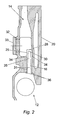
- Fig. 2 is a fragmentary cross-sectional view of a portion of an internal combustion engine illustrating a first embodiment of the present invention.
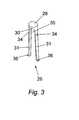
- Fig. 3 is a perspective view of a barrier device as illustrated in Fig. 2.
- Fig. 4 is a fragmentary cross-sectional view of a portion of an internal combustion engine illustrating a second embodiment of the present invention.
- Fig. 5 is a plan view of a barrier device as illustrated in Fig. 2.
- Fig 6. is a fragmentary cross sectional view of a portion of an internal combustion engine illustrating a third embodiment of the present invention.
- Fig. 7 is a fragmentary cross-sectional view taken along line 7-7 of Fig 6.
- Fig. 8 is a fragmentary cross-sectional view similar to Fig. 7, but showing an alternative arrangement.
- Fig. 9 is a fragmentary cross sectional view of a portion of an internal combustion engine illustrating a fourth embodiment of the present invention.
- Fig. 10 is a fragmentary, top plan view looking in the direction of arrows 10-10 of Fig. 9.
-
- For clarity the following description refers to a single cylinder engine only, but the principle can of course as easily be applied to multiple cylinder engines.
- With reference to Fig 1. an
internal combustion engine 10 according to this invention has a first chamber such as a tappet orcamshaft chamber 12, a second chamber such as avent chamber 14 and apassage 16 connecting the two chambers.Engine 10 further comprises acylinder head 18, acylinder block 20, agasket 22 positioned betweencylinder block 20 andcylinder head 18 and acrankcase 24. Blow-by gasses to be vented fromcrankcase 24 flow fromcrankcase 24 through respectivelytappet chamber 12,passage 16,vent chamber 14, and gasket 22 tocylinder head 18. The oil particles carried by the gasses are mainly introduced before the gasses enterpassage 16. - Four embodiments of this invention are described below in detail. Generally, each embodiment comprises an impact surface which is positioned adjacent to the downstream side of a passage connecting a first chamber and a second chamber. The passage has a both pre-determined cross-sectional area and shape such that the gas flow through the passage maintains or obtains a velocity within a pre-determined velocity range so it causes the oil particles carried by the gas flow to impact on the impact surface preferably with minimal atomisation of the particles on impact. The gas flow can continue, but the inertial impact of the oil particles on the impact surface cause the oil particles to coagulate and form oil droplets. As the droplets reach a certain size they depart from the impact surface and the droplets return to the first chamber .
- Figs. 2 and 3 illustrate a first embodiment of this invention. A barrier device, generally designated 26, is positioned adjacent to
passage 16 incylinder block 20.Barrier device 26 is preferably made from a plastic material, but other suitable materials such as metals or composites can also be used.Barrier device 26 comprisesimpact member 28 havingimpact surface 30 and at least one but preferably two or more supportingmembers 31 havinglower abutments 34 andupper abutments 36. Supportingmembers 31 in combination withabutments secure barrier device 26 by means of a snap-fit inpassage 16. -
Barrier device 26 is fitted inchamber 14 viaaperture 32. After fittingbarrier device 26 and carrying out any other desired operations,aperture 32 is closed off by for example press-fitting orthreading plug 33 intoaperture 32. - The gas flow carrying the oil particles travels at a velocity within a desired velocity range after leaving
passage 16. The gas flow continues by flowing throughapertures 35 between supportingmembers 31. The inertia of the oil particles causes the oil particles to impact onimpact surface 30, and thus the oil particles coagulate to form oil droplets. As the droplets reach a certain size they depart fromimpact surface 30 and the droplets either fall back throughpassage 16 or run back via supportingmembers 31 intotappet chamber 12. - Figs. 4 and 5 show a second embodiment of the present invention, wherein a barrier device, generally designated 126, is fitted adjacent to the downstream side of
passage 116 incylinder block 120.Barrier device 126 is preferably made from a plastic material, but other suitable materials such as metals or composites can also be used.Barrier device 126 comprises abody 137 having a generally rectangular shape, but thebody 137 could have any other suitable shape.Body 137 comprises a plurality of locating portions such astabs 138, animpact member 128 havingimpact surface 130,cross-members 139, and one ormore perforations 140. -
Barrier device 126 is fitted inchamber 114 viaaperture 132. After fitting barrier device 118 and carrying out any other desired operations,aperture 132 is closed off by for example press-fitting or threadingplug 133 intoaperture 132. -
Barrier device 126 is secured by engaging locatingportions 138 in receiving portions such as recesses (not shown) formed by the walls that definechamber 114. - The gas flow carrying the oil particles travels at a velocity within a desired velocity range after leaving
passage 116. The gas flow continues by flowing throughperforations 140. The inertia of the oil particles causes the oil particles to impact onimpact surface 130, and thus the oil particles coagulate to form oil droplets. As the droplets reach a certain size they depart fromimpact surface 130 and the droplets fall back throughpassage 116. - Figs. 6, 7, and 8 illustrate a third embodiment of the present invention, wherein a
barrier device 226 projects from aninner wall surface 227 ofcylinder block 220 adjacent to the downstream side ofpassage 116.Impact member 226 is preferably made from metal, but other suitable materials such as plastics or composites can also be used.Barrier device 226 can be an integral cast part ofcylinder block 220 or, alternatively it can be fitted afterblock 220 has been cast by methods well known to those skilled in the art, such as a press-fit or by using an adhesive. - If
barrier device 226 is fitted after casting ofcylinder block 220,barrier device 226 is fitted inchamber 214 viaaperture 132. After fittingbarrier device 226 and carrying out any other desired operations,aperture 232 is closed off by for example press-fitting or threadingplug 233 intoaperture 232. - The gas flow carrying the oil particles travels at a velocity within a desired velocity range after leaving
passage 216. The gas flow continues by flowing aroundimpact member 226. The inertia of the oil particles causes the oil particles to impact onimpact surface 230, and thus the oil particles coagulate to form oil droplets. As the droplets reach a certain size they depart fromimpact surface 230 and the droplets fall back throughpassage 216. - An alternative shaped barrier device is shown in Fig. 8 wherein
impact surface 230 is arcuate as opposed to the generally flat surface as shown in Figs. 6 and 7. - In Figs. 9 and 10 an
internal combustion engine 310 comprises acylinder block 320, a cylinder head (not shown) and agasket 322 disposed betweencylinder block 320 and the cylinder head.Gasket 322, which can be conventional except as described herein, comprises a body 350, at least one barrier device orimpact portion 326 projecting from body 350 havingimpact surface 330, and at least oneperforation 356.Gasket 322 can be considered part ofcylinder block 320 for the purpose of this invention.Cylinder block 320 comprisesvent chamber 314 havingthroat area 358,passage 316 andtappet chamber 312. - The embodiment shown in Figs. 9 and 10 uses the same general principle as described with regards to Figs. 2 to 8 with the main difference being the impact member has been repositioned.
-
Impact portion 326 is positioned in such a manner that the gas flow carrying the oil particles leavingthroat area 358 ofchamber 314 are obstructed byimpact portion 326.Throat area 358 has a both pre-determined cross-sectional area and shape such that the gas flow through the throat area maintains or obtains a velocity within a pre-determined velocity range so it causes the oil particles carried by the gas flow to impact on theimpact surface 330 preferably with minimal atomisation of the particles on impact. Thereforethroat area 358 functions similarly topassages throat area 358 can be considered a passage for purposes of this invention. - The gas flow carrying the oil particles travels at a velocity within a desired velocity range after leaving
throat area 358. The gas flow continues by flowing aroundimpact portion 326. The inertia of the oil particles causes them to impact onimpact surface 330, and thus the oil particles coagulate to form oil droplets. As the droplets reach a certain size they depart fromimpact surface 330 and the droplets fall and run back throughvent chamber 314 intopassage 316 and then intotappet chamber 312. - In use, this invention provides a simple and robust solution to reduce the amount of liquid oil particles carried over to a crankcase ventilation oil filter or to the induction system of an engine. Gas flow from the
crankcase 24 passes through apassage cylinder block impact surface impact surface - This invention can be readily fitted to existing engine designs without requiring substantial modification to the engine design. Moreover, because the invention is generally contained within the engine, the benefits of the invention can be obtained without increasing the space claim of the engine. In some cases, this invention may also be fitting to existing engines.
- This invention is particularly useful in engine application that are likely to generate high levels of oil particles carried by the crankcase gases. One example of such an application is an engine for a hydraulic excavator. In a hydraulic excavator, the repeated slewing of the excavator during digging operations can cause increased splashing of oil within the engine, thereby increasing the likelihood that small oil particles will travel with the gas flow. For applications that present particularly high levels of oil particles in the gas flow, those skilled in the art will recognize that one of more of the embodiments of Figs. 2-8 can be combined with the embodiment of Figs. 9 - 10 to further reduce oil carry over.
- Although the preferred embodiments of this invention have been described, improvements and modifications may be incorporated without departing from the scope of the following claims.
Claims (12)
- An internal combustion engine comprising:a cylinder block defining a first chamber, a second chamber and a passage connecting said first chamber and said second chamber, said passage allowing gas flow between said first chamber and said second chamber; anda barrier device positioned in said cylinder block having an impact surface located in said gas flow adjacent to a downstream end of said passage, said impact surface substantially impeding oil particles in said gas flow whilst allowing gas to flow past said impact surface.
- The internal combustion engine of claim 1 wherein said passage is configured to cause said oil particles in said gas flow to have a velocity sufficient to impact said impact surface.
- The internal combustion engine of any preceding claim wherein said barrier device is secured in the cylinder block by a snap-fit arrangement.
- The internal combustion engine of any preceding claim wherein said barrier device has at least one locating portion that engages with said cylinder block to locate said impact surface in said gas flow.
- The internal combustion engine of any preceding claim wherein said barrier device includes a body having at least one perforation to allow gas to flow past the barrier device.
- The internal combustion engine of any preceding claim wherein said barrier device is positioned in said cylinder block after casting of said cylinder block.
- The internal combustion engine of any preceding claim wherein said barrier device has at least one locating portion extending in said passage.
- The internal combustion engine of claim 1 or 2 wherein said barrier device is a cast part of said cylinder block.
- The internal combustion engine of any of claims 1,2,4, 6, and 8 wherein said barrier device projects from an internal wall surface of said cylinder block.
- The internal combustion engine of any of claims 1, 2, 5, and 6 wherein said barrier device is formed at least in part by a sealing gasket.
- A sealing arrangement for an internal combustion engine, comprising:a gasket adapted to provide a seal between a pair of adjacent engine components, said gasket having at least one perforation to allow gas flow between said pair of engine components; anda barrier device having an impact surface adapted to be positioned in said gas flow to substantially impede oil particles in said gas flow whilst allowing gas to flow past said barrier device.
- The sealing arrangement of claim 11 wherein a portion of said gasket forms said barrier device.
Priority Applications (2)
| Application Number | Priority Date | Filing Date | Title |
|---|---|---|---|
| EP20030252618 EP1471218A1 (en) | 2003-04-25 | 2003-04-25 | Internal combustion engine having an internal barrier device to reduce oil carry-over |
| US10/830,233 US7055510B2 (en) | 2003-04-25 | 2004-04-23 | Internal combustion engine having an internal barrier device to reduce oil carry-over |
Applications Claiming Priority (1)
| Application Number | Priority Date | Filing Date | Title |
|---|---|---|---|
| EP20030252618 EP1471218A1 (en) | 2003-04-25 | 2003-04-25 | Internal combustion engine having an internal barrier device to reduce oil carry-over |
Publications (1)
| Publication Number | Publication Date |
|---|---|
| EP1471218A1 true EP1471218A1 (en) | 2004-10-27 |
Family
ID=32946945
Family Applications (1)
| Application Number | Title | Priority Date | Filing Date |
|---|---|---|---|
| EP20030252618 Withdrawn EP1471218A1 (en) | 2003-04-25 | 2003-04-25 | Internal combustion engine having an internal barrier device to reduce oil carry-over |
Country Status (2)
| Country | Link |
|---|---|
| US (1) | US7055510B2 (en) |
| EP (1) | EP1471218A1 (en) |
Cited By (1)
| Publication number | Priority date | Publication date | Assignee | Title |
|---|---|---|---|---|
| EP3477067A4 (en) * | 2016-06-23 | 2019-06-26 | Yanmar Co., Ltd. | MOTOR DEVICE |
Families Citing this family (6)
| Publication number | Priority date | Publication date | Assignee | Title |
|---|---|---|---|---|
| JP4661733B2 (en) * | 2006-08-22 | 2011-03-30 | マツダ株式会社 | Engine oil separator device |
| JP4433048B2 (en) * | 2007-12-27 | 2010-03-17 | トヨタ自動車株式会社 | Internal combustion engine |
| JP2010096154A (en) * | 2008-10-20 | 2010-04-30 | Aichi Mach Ind Co Ltd | Vapor-liquid separating structure |
| NL2006586C2 (en) * | 2011-04-11 | 2012-10-12 | Vialle Alternative Fuel Systems Bv | Assembly for use in a crankcase ventilation system, a crankcase ventilation system comprising such an assembly, and a method for installing such an assembly. |
| JP6291240B2 (en) * | 2013-12-12 | 2018-03-14 | ダイハツ工業株式会社 | Internal combustion engine |
| US10683796B2 (en) | 2016-03-30 | 2020-06-16 | General Electric Company | Systems and methods for reduced oil carryover |
Citations (8)
| Publication number | Priority date | Publication date | Assignee | Title |
|---|---|---|---|---|
| US1329343A (en) * | 1919-07-11 | 1920-01-27 | Raba Ernest | Combined gasket and oil-gasifier |
| DE346979C (en) * | 1922-01-11 | Richard Weyl | Circulating lubrication for the crank mechanism of internal combustion engines, especially bicycle engines, in which a negative pressure is generated in the crankcase by piston displacement and a vent valve | |
| US3241537A (en) * | 1961-11-06 | 1966-03-22 | Oscar F Jones | Volumetric controlled crankcase ventilation systems |
| US4922881A (en) * | 1987-12-29 | 1990-05-08 | Kawasaki Jukogyo Kabushiki Kaisha | Breather device for an internal combustion engine |
| GB2260365A (en) * | 1991-10-03 | 1993-04-14 | Jaguar Cars | Oil Separation from i.c. engine crankcase gases |
| JPH06336911A (en) * | 1993-05-27 | 1994-12-06 | Toyota Autom Loom Works Ltd | Lubricating oil separating device and gasket therewith |
| JPH08189325A (en) * | 1995-01-10 | 1996-07-23 | Kawasaki Heavy Ind Ltd | Breather device for 4-cycle engine |
| EP1199448A1 (en) * | 2000-10-17 | 2002-04-24 | IVECO FIAT S.p.A. | Internal-combustion engine provided with a purifying device for the separation of particles of lubricating oil from the crankcase blow-by gases |
Family Cites Families (9)
| Publication number | Priority date | Publication date | Assignee | Title |
|---|---|---|---|---|
| US1893183A (en) * | 1930-09-20 | 1933-01-03 | Superior Engine Company | Air manifold for internal combustion engines |
| US2252974A (en) * | 1938-05-27 | 1941-08-19 | Donaldson Co Inc | Crankcase ventilating system |
| JPS60192821A (en) * | 1984-03-15 | 1985-10-01 | Honda Motor Co Ltd | Crankcase ventilation device for internal combustion engines |
| JPH0723531Y2 (en) * | 1988-10-18 | 1995-05-31 | 日産自動車株式会社 | Blow-by gas recirculation system for engines |
| US5617834A (en) * | 1996-03-05 | 1997-04-08 | Ford Motor Company | Air-oil separator for a crankcase ventilation system in an internal combustion engine |
| SE521667C2 (en) * | 1999-06-07 | 2003-11-25 | Volvo Personvagnar Ab | Internal combustion engine |
| JP3911950B2 (en) * | 2000-02-25 | 2007-05-09 | スズキ株式会社 | Motorcycle |
| US6443136B1 (en) * | 2000-10-25 | 2002-09-03 | Honda Giken Kogyo Kabushiki Kaisha | Breather apparatus for an internal combustion engine |
| US6435170B1 (en) * | 2001-08-01 | 2002-08-20 | Dana Corporation | Crankcase bypass system with oil scavenging device |
-
2003
- 2003-04-25 EP EP20030252618 patent/EP1471218A1/en not_active Withdrawn
-
2004
- 2004-04-23 US US10/830,233 patent/US7055510B2/en not_active Expired - Fee Related
Patent Citations (8)
| Publication number | Priority date | Publication date | Assignee | Title |
|---|---|---|---|---|
| DE346979C (en) * | 1922-01-11 | Richard Weyl | Circulating lubrication for the crank mechanism of internal combustion engines, especially bicycle engines, in which a negative pressure is generated in the crankcase by piston displacement and a vent valve | |
| US1329343A (en) * | 1919-07-11 | 1920-01-27 | Raba Ernest | Combined gasket and oil-gasifier |
| US3241537A (en) * | 1961-11-06 | 1966-03-22 | Oscar F Jones | Volumetric controlled crankcase ventilation systems |
| US4922881A (en) * | 1987-12-29 | 1990-05-08 | Kawasaki Jukogyo Kabushiki Kaisha | Breather device for an internal combustion engine |
| GB2260365A (en) * | 1991-10-03 | 1993-04-14 | Jaguar Cars | Oil Separation from i.c. engine crankcase gases |
| JPH06336911A (en) * | 1993-05-27 | 1994-12-06 | Toyota Autom Loom Works Ltd | Lubricating oil separating device and gasket therewith |
| JPH08189325A (en) * | 1995-01-10 | 1996-07-23 | Kawasaki Heavy Ind Ltd | Breather device for 4-cycle engine |
| EP1199448A1 (en) * | 2000-10-17 | 2002-04-24 | IVECO FIAT S.p.A. | Internal-combustion engine provided with a purifying device for the separation of particles of lubricating oil from the crankcase blow-by gases |
Non-Patent Citations (2)
| Title |
|---|
| PATENT ABSTRACTS OF JAPAN vol. 1995, no. 03 28 April 1995 (1995-04-28) * |
| PATENT ABSTRACTS OF JAPAN vol. 1996, no. 11 29 November 1996 (1996-11-29) * |
Cited By (2)
| Publication number | Priority date | Publication date | Assignee | Title |
|---|---|---|---|---|
| EP3477067A4 (en) * | 2016-06-23 | 2019-06-26 | Yanmar Co., Ltd. | MOTOR DEVICE |
| US10612425B2 (en) | 2016-06-23 | 2020-04-07 | Yanmar Co., Ltd. | Engine device |
Also Published As
| Publication number | Publication date |
|---|---|
| US7055510B2 (en) | 2006-06-06 |
| US20050011503A1 (en) | 2005-01-20 |
Similar Documents
| Publication | Publication Date | Title |
|---|---|---|
| US7047955B2 (en) | Crankcase emission control device | |
| US8794220B2 (en) | Blow-by gas recirculating apparatus for an engine | |
| CN102892982B (en) | Engine blow-by gas treatment device | |
| CN102251827A (en) | Engine including positive crankcase ventilation | |
| CN101680320A (en) | Breather device for engine | |
| US7055510B2 (en) | Internal combustion engine having an internal barrier device to reduce oil carry-over | |
| CN104295340A (en) | Dual flow check valve for positive crankcase ventilation system | |
| CN103782000B (en) | engine ventilation | |
| GB2441404A (en) | Baffle arrangement for separating liquid oil from blow-by gas in an i.c. engine | |
| CN111188669B (en) | Air-oil separator | |
| US20130104817A1 (en) | Engine assembly including crankcase ventilation system | |
| JPS6187931A (en) | Apparatus for adjusting number of rotations of idling | |
| JPH0577523U (en) | Blow-by gas passage structure of engine | |
| JP2005220883A (en) | Upper body structure of engine | |
| JP2003120245A (en) | Intake device for internal combustion engine | |
| EP1063413A2 (en) | Four-stroke cycle engine | |
| US7124752B2 (en) | Deflector for limiting the ingress of liquid oil | |
| CN107989671B (en) | Integrated oil separator assembly for crankcase ventilation | |
| US20240369004A1 (en) | Crankcase ventilation element | |
| US11230998B2 (en) | Ventilation apparatus of internal combustion engine | |
| JP2000045746A (en) | Internal pressure control device for internal combustion engine crankcase | |
| KR20060003924A (en) | Cylinder head cover structure of car engine | |
| KR100622488B1 (en) | Blowout Reduction Structure of Engine Blow-by Gas | |
| JP2019090386A (en) | Blow-by gas treatment device | |
| JPH02233817A (en) | Engine intake quantity controller |
Legal Events
| Date | Code | Title | Description |
|---|---|---|---|
| PUAI | Public reference made under article 153(3) epc to a published international application that has entered the european phase |
Free format text: ORIGINAL CODE: 0009012 |
|
| AK | Designated contracting states |
Kind code of ref document: A1 Designated state(s): AT BE BG CH CY CZ DE DK EE ES FI FR GB GR HU IE IT LI LU MC NL PT RO SE SI SK TR |
|
| AX | Request for extension of the european patent |
Extension state: AL LT LV MK |
|
| 17P | Request for examination filed |
Effective date: 20050425 |
|
| AKX | Designation fees paid |
Designated state(s): DE GB |
|
| 17Q | First examination report despatched |
Effective date: 20090319 |
|
| STAA | Information on the status of an ep patent application or granted ep patent |
Free format text: STATUS: THE APPLICATION IS DEEMED TO BE WITHDRAWN |
|
| 18D | Application deemed to be withdrawn |
Effective date: 20090930 |