EP1470368B1 - A valve unit for modulating the delivery pressure of a gas - Google Patents
A valve unit for modulating the delivery pressure of a gas Download PDFInfo
- Publication number
- EP1470368B1 EP1470368B1 EP02712271A EP02712271A EP1470368B1 EP 1470368 B1 EP1470368 B1 EP 1470368B1 EP 02712271 A EP02712271 A EP 02712271A EP 02712271 A EP02712271 A EP 02712271A EP 1470368 B1 EP1470368 B1 EP 1470368B1
- Authority
- EP
- European Patent Office
- Prior art keywords
- valve
- pressure
- closure element
- valve unit
- servo
- Prior art date
- Legal status (The legal status is an assumption and is not a legal conclusion. Google has not performed a legal analysis and makes no representation as to the accuracy of the status listed.)
- Expired - Lifetime
Links
Images

Classifications
-
- F—MECHANICAL ENGINEERING; LIGHTING; HEATING; WEAPONS; BLASTING
- F23—COMBUSTION APPARATUS; COMBUSTION PROCESSES
- F23N—REGULATING OR CONTROLLING COMBUSTION
- F23N1/00—Regulating fuel supply
- F23N1/007—Regulating fuel supply using mechanical means
-
- G—PHYSICS
- G05—CONTROLLING; REGULATING
- G05D—SYSTEMS FOR CONTROLLING OR REGULATING NON-ELECTRIC VARIABLES
- G05D16/00—Control of fluid pressure
- G05D16/20—Control of fluid pressure characterised by the use of electric means
- G05D16/2093—Control of fluid pressure characterised by the use of electric means with combination of electric and non-electric auxiliary power
- G05D16/2095—Control of fluid pressure characterised by the use of electric means with combination of electric and non-electric auxiliary power using membranes within the main valve
-
- F—MECHANICAL ENGINEERING; LIGHTING; HEATING; WEAPONS; BLASTING
- F23—COMBUSTION APPARATUS; COMBUSTION PROCESSES
- F23N—REGULATING OR CONTROLLING COMBUSTION
- F23N2225/00—Measuring
- F23N2225/04—Measuring pressure
- F23N2225/06—Measuring pressure for determining flow
-
- F—MECHANICAL ENGINEERING; LIGHTING; HEATING; WEAPONS; BLASTING
- F23—COMBUSTION APPARATUS; COMBUSTION PROCESSES
- F23N—REGULATING OR CONTROLLING COMBUSTION
- F23N2235/00—Valves, nozzles or pumps
- F23N2235/12—Fuel valves
- F23N2235/16—Fuel valves variable flow or proportional valves
-
- F—MECHANICAL ENGINEERING; LIGHTING; HEATING; WEAPONS; BLASTING
- F23—COMBUSTION APPARATUS; COMBUSTION PROCESSES
- F23N—REGULATING OR CONTROLLING COMBUSTION
- F23N2235/00—Valves, nozzles or pumps
- F23N2235/12—Fuel valves
- F23N2235/20—Membrane valves
-
- F—MECHANICAL ENGINEERING; LIGHTING; HEATING; WEAPONS; BLASTING
- F23—COMBUSTION APPARATUS; COMBUSTION PROCESSES
- F23N—REGULATING OR CONTROLLING COMBUSTION
- F23N2235/00—Valves, nozzles or pumps
- F23N2235/12—Fuel valves
- F23N2235/24—Valve details
-
- Y—GENERAL TAGGING OF NEW TECHNOLOGICAL DEVELOPMENTS; GENERAL TAGGING OF CROSS-SECTIONAL TECHNOLOGIES SPANNING OVER SEVERAL SECTIONS OF THE IPC; TECHNICAL SUBJECTS COVERED BY FORMER USPC CROSS-REFERENCE ART COLLECTIONS [XRACs] AND DIGESTS
- Y10—TECHNICAL SUBJECTS COVERED BY FORMER USPC
- Y10T—TECHNICAL SUBJECTS COVERED BY FORMER US CLASSIFICATION
- Y10T137/00—Fluid handling
- Y10T137/7722—Line condition change responsive valves
- Y10T137/7758—Pilot or servo controlled
- Y10T137/7761—Electrically actuated valve
Abstract
Description
- The present invention relates to a valve unit for modulating the delivery pressure of a gas according to the preamble to main
Claim 1. Such a valve is known, from documentEP-A-1 058 060 . - Valve units of the type indicated are used widely for controlling the delivery of a fuel gas to a burner or other similar user, particularly but not exclusively in heating apparatus.
- In these units, it is known to regulate the delivery pressure (and consequently the flow-rate) of the gas in controlled manner by modulation between a minimum pressure and a maximum pressure performed by a servo-valve which is subservient to a modulation unit with a diaphragm. The servo-valve typically comprises a closure element which can be opened by a diaphragm that is sensitive to the pressure differential existing between the pressure in the delivery duct and a control pressure. This control pressure is controlled by the operation of a modulation valve.
- A valve unit having the above-mentioned characteristics is known from the Applicant's
European application EP 1058060 . In this application, the actuator of the modulation valve is controlled by an oscillating control signal (for example, an electrical voltage signal) with a predetermined "duty cycle" in order consequently to generate an oscillating control-pressure signal the integrated mean value of which is a function of the preselected "duty cycle". A limitation which may be encountered in the above-mentioned valve unit lies in the fact that the control-pressure value which is sensitive to the modulation is represented by a mean value of the pressure reached within a certain period of time, so that, by its very nature, the gas delivery-pressure regulation function is rendered less accurate. - Moreover, the control of the modulation valve is quite complex since it requires a control circuit which is arranged to control the regulation of the "duty cycle" during the valve-modulation operation.
- The object of the present invention is to provide a valve unit which ensures improved and more accurate modulation control of the gas-delivery pressure, achieved by a modulation valve and a respective actuator for the operation thereof with a simplified structure but at the same time such as to overcome the limitations discussed with reference to the prior art mentioned.
- This object and others which will become clearer from the following description are achieved by the invention by means of a valve unit formed in accordance with the appended claims.
- Further characteristics and advantages of the invention will become clearer from the following detailed description of a preferred embodiment thereof, described by way of non-limiting example, with reference to the appended drawings, in which:
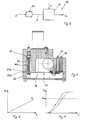
- Figure 1 is a schematic longitudinal section through a valve unit formed in accordance with the invention,
- Figure 2 is a view corresponding to that of Figure 1, of a variant of the invention,
- Figure 3 is a schematic block diagram of a second variant of the valve unit according to the invention,
- Figure 4 is a view corresponding to that of Figure 3, of a further variant of the invention,
- Figure 5 is a section through a detail of the valve unit of the preceding drawings,
- Figure 6 is a graph of a characteristic pressure-voltage curve of the valve unit according to the embodiment of Figure 3,
- Figure 7 is a graph of a characteristic pressure-voltage curve of the valve unit according to the embodiment of Figure 4.
- With reference initially to Figure 1, a valve unit according to the present invention for modulating the delivery pressure of a fuel gas delivered to a burner or other similar user, not shown in the drawing, is generally indicated 1. The fuel gas is supplied in the
unit 1 through amain duct 2 between an inlet opening 3 and an outlet opening 4. - The
valve unit 1 also comprises a servo-valve 5 mounted in themain duct 2 and including aclosure element 6 which is urged resiliently into closure on avalve seat 7 by the resilient load of a spring 7a and can be opened by adiaphragm 8 which is sensitive to the pressure differential existing between the pressure Pu at theoutlet 4, on one side, and to the pressure Pt in acontrol chamber 9, on the other side. The control-pressure value Pt is controlled by the operation of a pressure-regulation device, generally indicated 10 and described in detail below. - The
unit 1 also has asafety valve 11 disposed in theduct 2, upstream of thepressure regulator 10 and controlled, for example, by an electromagnetic unit (not shown) of conventional structure for shutting off the gas-flow in theduct 2 in the absence of a power supply to the electromagnetic unit controlling the safety valve. - The
control chamber 9 is in flow communication with themain duct 2 through aduct 12 for tapping off gas, withopposed ends end 12a, theduct 12 opens into themain duct 2, upstream of the servo-valve 5. - The
control chamber 9 also communicates with the outlet opening 4 of theduct 2 through atransfer duct 13 having aconstriction 14 in the region of theopening 4. Moreover, a delivery nozzle disposed at theoutlet 4 of the unit, downstream of theconstriction 14, is indicated 14a. - The
regulator 10 comprises avalve seat 15 formed in thetapping duct 12, preferably in the region of theend 12a, and acorresponding closure element 16 which is moved so as to close/open theseat 15 by an actuator means, generally indicated 17. Theactuator 17 is of the piezoelectric type, for example, of the type comprising adouble metal plate 18 extending along a predominant longitudinal axis between opposed ends 18a, 18b. - The piezoelectric actuator is connected, at its end 18a, to the body of the
closure element 16 and carries, at its opposite end 18b, a pair ofterminals 19 for the electrical supply of the actuator. - With particular reference to Figure 5, the
closure element 16 has a rod 16a carrying, at one end, ahead 20 of the closure element with a curved surface, preferably in the form of a spherical cap, acting on thevalve seat 15. At the opposite end, the rod is acted on by aspring 21 for urging theclosure element 16 resiliently into closure on thevalve seat 15 in opposition to the opening action of the piezoelectric actuator. - The end 18a of the actuator acts between a pair of
opposed abutment surfaces 22a, 22b defined by an opening formed in the rod 16a. The distance between the opposed abutments is selected in a manner such that the end 18a of theelement 18 remains spaced from theabutment surface 22b in the absence of an electrical supply to the piezoelectric actuator so as to permit safety closure of thevalve seat 15 under the effect of the resilient action of thespring 21 alone in this condition. - The
element 18 of the piezoelectric actuator is selected in a manner such that the displacement brought about in theclosure element 16 relative to thevalve seat 15 is correlated proportionally with the control signal sent to the actuator, for example, an electrical voltage signal. By virtue of the correlation between the lifting movement of theclosure element 16 and the control pressure Pt produced in thechamber 9, for a preselected value of the above-mentioned control signal, a corresponding value of the control pressure Pt is unequivocally generated so that the delivery pressure Pu is consequently modulated in a correlated manner. - The graph of Figure 6 shows a characteristic curve of the control pressure Pt as a function of the supply voltage V of the piezoelectric actuator for a predetermined input pressure Pi in the
main duct 2. For example, an almost linear regulation curve Pt-V (and consequently Pu-V) can advantageously be obtained, in which the pressure modulation takes place regularly and precisely for each preselected value of the delivery pressure required. - Figure 2 shows a first variant of the invention, generally indicated 40, in which details similar to those of the previous embodiment are indicated by the same reference numerals. This variant differs from the
valve unit 1 mainly in that a maximum delivery-pressure regulator, generally indicated 41 in Figure 2, is provided downstream of the servo-valve 5. Theregulator 41 comprises aclosure element 42 controlled by adiaphragm 43 and urged resiliently into closure on avalve seat 44 by the resilient load of aspring 45. The resilient load is adjustable by screwing of aspring holder 46. Thevalve seat 44 is formed at the end of aduct 47 which is in communication, at its opposite end, with thetransfer valve 13. The valve seat in turn is in communication, downstream of theclosure element 42, with achamber 49 communicating with theoutlet duct 4 through a duct 49a. The duct 49a opens into theoutlet duct 4 downstream of theconstriction 14. Moreover, theclosure element 42 can be operated, so as to open therespective seat 44 by thediaphragm 43 which is sensitive; on the one hand to the pressure Pu (acting in the chamber 49) and, on the other hand, to the resilient force of thespring 45, less a reference pressure Pref (acting on thediaphragm 43 from the side remote from the chamber 49), for example, equal to atmospheric pressure. The reference pressure Pref may, for example, be selected so as to be equal to the pressure existing downstream of the nozzle 14a. Upon the assumption that the pressure exerted by thespring 45 can be expressed as the ratio between the resilient force of the spring 45 (equivalent pressure) and an equivalent area of thediaphragm 43, when the output pressure Pu exceeds the equivalent pressure value, theclosure element 42 is moved so as to open theseat 44, consequently increasing the cross-section for the gas-flow, thus limiting the maximum value of the output pressure Pu to the equivalent pressure value. For values of the pressure Pu below the equivalent pressure value, the delivery pressure is modulated by theregulator device 10, as described above, up to the maximum pressure value which can be reached, which can be set by regulation of the resilient load on thespring holder 46. - In this case, a characteristic curve of the type shown in Figure 7 is representative of the behaviour of the delivery pressure as a function of the voltage control signal V supplied to the piezoelectric actuator. It will be noted that the maximum delivery pressure is limited to the value (Pmax) set which is adjustable by means of the
maximum adjustment screw 46 of Figure 2. It is thus possible to achieve a precise adjustment of the maximum output-pressure value. - Figure 3 shows, by means of a block diagram, a variant of the invention, generally indicated 50, in which details similar to those of the previous embodiment are indicated by the same reference numerals. This variant differs from the above-described
valve unit 1 mainly in that a feedback system is provided in the modulation control of the delivery pressure. - For this purpose, the
valve unit 50 is provided with a pressure (or flow-rate) detector with asensor 51 disposed in theduct 2 downstream of the servo-valve 5, in the region of the outlet opening 4. The unit also comprises a feedback control circuit, indicated 52, which is arranged to receive, as an input, a signal correlated with the pressure value detected by thesensor 51. The unit also includes comparison means 53 for comparing the value measured with a preset value relating to a preselected pressure (or flow-rate) as well asmeans 54 for generating a control signal in dependence on the differential detected and sending it to the piezoelectric actuator so as to regulate the movement of theclosure element 16 in order to achieve the desired delivery-pressure value Pu. - It is pointed out that, with the feedback system of the above-mentioned variant, the delivery pressure value Pu which can be achieved is substantially independent of the pressure Pi of the gas supply to the valve unit.
- In this case, a characteristic curve of the type shown in Figure 7 is representative of the behaviour of the pressure Pt as a function of the control signal V, irrespective of any fluctuations or variations of the input pressure Pi.
- Figure 4 shows, in a block diagram, a further variant of the invention, generally indicated 60, in which details similar to those of the previous embodiments are indicated by the same reference numerals.
- The
unit 60 differs from the previous variant in that no feedback system is provided but it has a further valve, indicated 61, for regulating the maximum delivery pressure. The valve is disposed upstream of thepressure regulator 10 and is of conventional structure, for example, it is formed with a valve seat and a respective closure element acted on by a diaphragm which is subject to an adjustable resilient load. Adjustment of the resilient load, for example, by screwing of a spring-holder, enables a maximum threshold value to be set for the delivery pressure Pu which can be reached with modulation of the valve unit. - A regulation curve representative of the
unit 60 may be, for example, that shown in Figure 7, including the portions shown by broken lines. - The invention thus achieves the objects proposed, affording the above-mentioned advantages over known solutions.
- The main advantage lies in the fact that the valve unit according to the invention ensures improved and more accurate modulation control of the gas-delivery pressure which, moreover, is achieved with a simplified structure of the valve unit in comparison with known solutions.
Claims (6)
- A valve unit for modulating the delivery pressure of a gas, comprising:- a main duct (2) for the delivery of a gas-flow between an inlet opening (3) and an outlet opening (4),- a servo-valve (5) mounted in the duct (2) and having a first closure element (6) controlled by a diaphragm (8), the diaphragm being subjected to the gas-delivery pressure (Pu) on one side and, on the other side, to a control pressure (Pt) established in a corresponding control chamber (9) of the servo-valve (5),- a tapping duct (12) for tapping off the gas delivered to the inlet of the unit, communicating at its two opposite ends with the main duct (2), upstream of the servo-valve (5), and with the control chamber (9), respectively,- a pressure-regulation device (10) associated with the servo-valve (5) and including a valve seat (15) mounted in the tapping duct (12) and a respective second closure element (16) associated with the seat,- a piezoelectric actuator, associated with the second closure element (16) for the operative control thereof, and a control circuit for generating a control signal for the actuator characterized in that- the second closure element (16) is arranged to open and close said tapping duct,- the control circuit provides a variable amplitude control signal for the actuator,- the movement of the second closure element (16) relative to the corresponding valve seat (15) is correlated proportionally with the variable amplitude actuator-control signal so that, for a preselected signal value, a corresponding control-pressure value (Pt) is generated so as to modulate the delivery pressure (Pu) in a proportionally correlated manner,
- A valve unit according to Claim 1 in which the piezoelectric actuator (17) comprises a double-plate element (1.8) an operative end (18a) of which is connected to the second closure element (16).
- A valve unit according to Claim 1 or Claim 2 in which the control signal is a voltage-supply signal for the piezoelectric actuator (17).
- A valve unit according to any one of the preceding claims, comprising a feedback circuit (52) acting on the pressure regulator, said feedback circuit including means (51) for detecting the delivery pressure downstream of the servo-valve and comparison means (57) for comparing the detected delivery-pressure value with a preselected value and consequently generating a corresponding control signal for the piezoelectric actuator (17) so as to modulate the delivery pressure in order to achieve the preselected pressure value.
- A valve unit according to Claim 4 in which the detector means (51) are arranged to detect the flow-rate of gas delivered.
- A valve unit according to one or more of the preceding claims, comprising a further valve (61) for regulating the maximum delivery pressure, disposed upstream of the servo-valve (5) and of the pressure-regulator device (10).
Applications Claiming Priority (1)
| Application Number | Priority Date | Filing Date | Title |
|---|---|---|---|
| PCT/IT2002/000044 WO2003064928A1 (en) | 2002-01-29 | 2002-01-29 | A valve unit for modulating the delivery pressure of a gas |
Publications (2)
| Publication Number | Publication Date |
|---|---|
| EP1470368A1 EP1470368A1 (en) | 2004-10-27 |
| EP1470368B1 true EP1470368B1 (en) | 2007-07-18 |
Family
ID=27638228
Family Applications (1)
| Application Number | Title | Priority Date | Filing Date |
|---|---|---|---|
| EP02712271A Expired - Lifetime EP1470368B1 (en) | 2002-01-29 | 2002-01-29 | A valve unit for modulating the delivery pressure of a gas |
Country Status (7)
| Country | Link |
|---|---|
| US (1) | US20050081920A1 (en) |
| EP (1) | EP1470368B1 (en) |
| AT (1) | ATE367560T1 (en) |
| CA (1) | CA2474021A1 (en) |
| CZ (1) | CZ305381B6 (en) |
| DE (1) | DE60221290T2 (en) |
| WO (1) | WO2003064928A1 (en) |
Cited By (1)
| Publication number | Priority date | Publication date | Assignee | Title |
|---|---|---|---|---|
| TWI463287B (en) * | 2007-12-27 | 2014-12-01 | Horiba Stec Co | Flow rate ratio control device |
Families Citing this family (15)
| Publication number | Priority date | Publication date | Assignee | Title |
|---|---|---|---|---|
| AU2003265158A1 (en) * | 2003-09-08 | 2005-03-29 | Sit La Precisa S.P.A. | A system for controlling the delivery of a fuel gas to a burner apparatus |
| ITPD20040176A1 (en) * | 2004-07-02 | 2004-10-02 | Sit La Precisa Spa | MULTIFUNCTIONAL VALVE UNIT FOR THE CONTROL OF THE DELIVERY OF A COMBUSTIBLE GAS TOWARDS A BURNER APPLIANCE |
| AT502406B1 (en) * | 2006-03-22 | 2007-03-15 | Vaillant Austria Gmbh | Gas armature has throttle device for flow limiter, has throttle device positioned in outlet upstream measuring point in gas passage and over nozzle and over connection regulates with mounting fastened to threaded connection of outlet |
| DE102006019404A1 (en) * | 2006-04-24 | 2007-10-25 | Siemens Ag | Pressure regulator for gaseous media |
| WO2010091361A2 (en) * | 2009-02-08 | 2010-08-12 | Ap Solutions, Inc. | Plasma source and method for removing materials from substrates utilizing pressure waves |
| IT1394083B1 (en) * | 2009-03-25 | 2012-05-25 | Sit La Precisa Spa Con Socio Unico | REGULATOR DEVICE FOR THE COMBUSTIBLE GAS DELIVERY PRESSURE |
| EP2450630A3 (en) | 2010-11-03 | 2018-03-21 | Vaillant GmbH | Piezo gas valve |
| AT510172B1 (en) * | 2010-11-09 | 2012-02-15 | Vaillant Group Austria Gmbh | DEVICE AND METHOD FOR ADJUSTING A GASSTROMS, IN PARTICULAR FUELGASSTROMS |
| CN103893864B (en) * | 2012-12-26 | 2017-05-24 | 北京谊安医疗系统股份有限公司 | Turbine respirator pressure control ventilation method |
| CN103893865B (en) * | 2012-12-26 | 2017-05-31 | 北京谊安医疗系统股份有限公司 | A kind of method of lung ventilator turbine volume controlled ventilation |
| US10677461B2 (en) | 2015-10-12 | 2020-06-09 | Emerson Process Management Regulator Technologies, Inc. | Adjustable burner control valve |
| MX2018006317A (en) | 2015-11-22 | 2019-01-31 | Atmospheric Plasma Solutions Inc | Method and device for promoting adhesion of metallic surfaces. |
| US20170009696A1 (en) * | 2016-09-26 | 2017-01-12 | Caterpillar Inc. | System for controlling pressure of fuel supplied to engine |
| PL240787B1 (en) * | 2018-04-11 | 2022-06-06 | Politechnika Bialostocka | Piezoelectric gas injector, preferably for the combustion engine feeding systems |
| IT201800010571A1 (en) * | 2018-11-26 | 2020-05-26 | Sit Spa | Device for controlling the delivery of a combustible gas to a burner of a heater |
Family Cites Families (11)
| Publication number | Priority date | Publication date | Assignee | Title |
|---|---|---|---|---|
| US2370110A (en) * | 1942-09-02 | 1945-02-20 | Spence Engineering Company Inc | Safety device for reducing valves |
| US3354901A (en) * | 1965-05-18 | 1967-11-28 | Honeywell Inc | Control apparatus |
| US3526360A (en) * | 1968-10-18 | 1970-09-01 | Itt | Main line valve with pilot regulator |
| US4060370A (en) * | 1975-10-02 | 1977-11-29 | Emerson Electric Co. | Manifold gas valve with stepped flow operation |
| AT380934B (en) * | 1983-01-13 | 1986-07-25 | Enfo Grundlagen Forschungs Ag | ELECTRICAL-PNEUMATIC SIGNAL CONVERTER |
| JPH02138501A (en) * | 1988-11-17 | 1990-05-28 | Smc Corp | Nozzle flapper mechanism |
| DE69612184T2 (en) * | 1996-04-02 | 2001-09-06 | Sit La Precisa Spa | A valve unit for regulating the discharge pressure of a gas |
| US6056008A (en) * | 1997-09-22 | 2000-05-02 | Fisher Controls International, Inc. | Intelligent pressure regulator |
| IT1308113B1 (en) * | 1999-06-02 | 2001-11-29 | Sit La Precisa Spa | VALVE UNIT FOR THE MODULATION OF THE DELIVERY PRESSURE OF A GAS. |
| US6302495B1 (en) * | 1999-06-04 | 2001-10-16 | Ge Harris Railway Electronics, Llc | Railway car braking system including piezoelectric pilot valve and associated methods |
| AUPQ111199A0 (en) * | 1999-06-21 | 1999-07-15 | Email Limited | Regulator arrangement |
-
2002
- 2002-01-29 CZ CZ2004-846A patent/CZ305381B6/en not_active IP Right Cessation
- 2002-01-29 AT AT02712271T patent/ATE367560T1/en not_active IP Right Cessation
- 2002-01-29 DE DE2002621290 patent/DE60221290T2/en not_active Expired - Lifetime
- 2002-01-29 US US10/502,671 patent/US20050081920A1/en not_active Abandoned
- 2002-01-29 CA CA 2474021 patent/CA2474021A1/en not_active Abandoned
- 2002-01-29 WO PCT/IT2002/000044 patent/WO2003064928A1/en active IP Right Grant
- 2002-01-29 EP EP02712271A patent/EP1470368B1/en not_active Expired - Lifetime
Cited By (1)
| Publication number | Priority date | Publication date | Assignee | Title |
|---|---|---|---|---|
| TWI463287B (en) * | 2007-12-27 | 2014-12-01 | Horiba Stec Co | Flow rate ratio control device |
Also Published As
| Publication number | Publication date |
|---|---|
| WO2003064928A1 (en) | 2003-08-07 |
| DE60221290D1 (en) | 2007-08-30 |
| EP1470368A1 (en) | 2004-10-27 |
| CA2474021A1 (en) | 2003-08-07 |
| DE60221290T2 (en) | 2008-04-03 |
| ATE367560T1 (en) | 2007-08-15 |
| CZ305381B6 (en) | 2015-08-26 |
| US20050081920A1 (en) | 2005-04-21 |
| CZ2004846A3 (en) | 2004-12-15 |
Similar Documents
| Publication | Publication Date | Title |
|---|---|---|
| EP1470368B1 (en) | A valve unit for modulating the delivery pressure of a gas | |
| US6561791B1 (en) | Gas burner regulating system | |
| EP1264228B1 (en) | High volume electronic gas regulator | |
| US20040202975A1 (en) | Temperature controlled burner apparatus | |
| CA2302607A1 (en) | Intelligent pressure regulator | |
| US20120160186A1 (en) | Device for controlling the supply of fuel gas to a burner , in particular for water heater appliances | |
| US6595231B1 (en) | Device and method for regulating the pressure of a gas stream | |
| EP1058060A1 (en) | A valve unit for modulating the delivery pressure of a gas | |
| JP2010515993A (en) | Pressure regulator | |
| EP0800039B1 (en) | A valve unit for controlling the delivery pressure of a gas | |
| CA3081763C (en) | Methods and systems for air compressor with electric inlet valve control | |
| US20040099313A1 (en) | Fluid flow pressure regulator | |
| US4420113A (en) | Method of and system for controlling the operation of a heater | |
| US20060292505A1 (en) | System for controlling the delivery of a fuel gas to a burner apparatus | |
| AU2002232145A1 (en) | A valve unit for modulating the delivery pressure of a gas | |
| US4773443A (en) | Pressure reducer | |
| JPH05187897A (en) | Fluid measuring apparatus | |
| EP0783145B1 (en) | Improvements in or relating to meters | |
| RU2283458C2 (en) | Valve unit for modulating gas supply pressure | |
| WO2006003684A8 (en) | Multi-function valve for controlling the feed of a combustible gas to a burner apparatus | |
| EP1730443A1 (en) | A valve unit for cotrolling the supply of a fuel gas, particularly for cooking hobs and the like | |
| EP1039225A3 (en) | A valve unit for regulating the flow-rate of a fuel gas | |
| US20100108923A1 (en) | Electropneumatic transducer with a pneumatic pressure-regulating valve | |
| WO1989004442A1 (en) | Instantaneous hot water system | |
| EP0989366A1 (en) | A valve unit for automatically regulating the flow-rate of a fuel gas |
Legal Events
| Date | Code | Title | Description |
|---|---|---|---|
| PUAI | Public reference made under article 153(3) epc to a published international application that has entered the european phase |
Free format text: ORIGINAL CODE: 0009012 |
|
| 17P | Request for examination filed |
Effective date: 20040714 |
|
| AK | Designated contracting states |
Kind code of ref document: A1 Designated state(s): AT BE CH CY DE DK ES FI FR GB GR IE IT LI LU MC NL PT SE TR |
|
| AX | Request for extension of the european patent |
Extension state: AL LT LV MK RO SI |
|
| EL | Fr: translation of claims filed | ||
| REG | Reference to a national code |
Ref country code: FR Ref legal event code: ERR Free format text: BOPI DE PUBLICATION N: 04/50 PAGES: 213 PARTIE DU BULLETIN CONCERNEE: DEMANDES DE BREVETS EUROPEENS POUR LESQUELLES LA TRADUCTION DES REVENDICATIONS, ET EVENTUELLEMENT LA TRADUCTION REVISEE DES REVENDICATIONS ONT ETE REMISES A I'INPI IL Y A LIEU DE SUPPRIMER: LA MENTION DE LA REMISE DE LA TRADUCTION. CETTE PUBLICATION ETAIT SANS OBJET. |
|
| GRAP | Despatch of communication of intention to grant a patent |
Free format text: ORIGINAL CODE: EPIDOSNIGR1 |
|
| GRAS | Grant fee paid |
Free format text: ORIGINAL CODE: EPIDOSNIGR3 |
|
| GRAA | (expected) grant |
Free format text: ORIGINAL CODE: 0009210 |
|
| AK | Designated contracting states |
Kind code of ref document: B1 Designated state(s): AT BE CH CY DE DK ES FI FR GB GR IE IT LI LU MC NL PT SE TR |
|
| REG | Reference to a national code |
Ref country code: GB Ref legal event code: FG4D |
|
| REG | Reference to a national code |
Ref country code: CH Ref legal event code: EP |
|
| REF | Corresponds to: |
Ref document number: 60221290 Country of ref document: DE Date of ref document: 20070830 Kind code of ref document: P |
|
| REG | Reference to a national code |
Ref country code: IE Ref legal event code: FG4D |
|
| ET | Fr: translation filed | ||
| PG25 | Lapsed in a contracting state [announced via postgrant information from national office to epo] |
Ref country code: PT Free format text: LAPSE BECAUSE OF FAILURE TO SUBMIT A TRANSLATION OF THE DESCRIPTION OR TO PAY THE FEE WITHIN THE PRESCRIBED TIME-LIMIT Effective date: 20071218 Ref country code: FI Free format text: LAPSE BECAUSE OF FAILURE TO SUBMIT A TRANSLATION OF THE DESCRIPTION OR TO PAY THE FEE WITHIN THE PRESCRIBED TIME-LIMIT Effective date: 20070718 Ref country code: ES Free format text: LAPSE BECAUSE OF FAILURE TO SUBMIT A TRANSLATION OF THE DESCRIPTION OR TO PAY THE FEE WITHIN THE PRESCRIBED TIME-LIMIT Effective date: 20071029 |
|
| REG | Reference to a national code |
Ref country code: CH Ref legal event code: PL |
|
| PG25 | Lapsed in a contracting state [announced via postgrant information from national office to epo] |
Ref country code: CH Free format text: LAPSE BECAUSE OF FAILURE TO SUBMIT A TRANSLATION OF THE DESCRIPTION OR TO PAY THE FEE WITHIN THE PRESCRIBED TIME-LIMIT Effective date: 20070718 Ref country code: AT Free format text: LAPSE BECAUSE OF FAILURE TO SUBMIT A TRANSLATION OF THE DESCRIPTION OR TO PAY THE FEE WITHIN THE PRESCRIBED TIME-LIMIT Effective date: 20070718 Ref country code: LI Free format text: LAPSE BECAUSE OF FAILURE TO SUBMIT A TRANSLATION OF THE DESCRIPTION OR TO PAY THE FEE WITHIN THE PRESCRIBED TIME-LIMIT Effective date: 20070718 |
|
| PG25 | Lapsed in a contracting state [announced via postgrant information from national office to epo] |
Ref country code: BE Free format text: LAPSE BECAUSE OF FAILURE TO SUBMIT A TRANSLATION OF THE DESCRIPTION OR TO PAY THE FEE WITHIN THE PRESCRIBED TIME-LIMIT Effective date: 20070718 |
|
| PG25 | Lapsed in a contracting state [announced via postgrant information from national office to epo] |
Ref country code: GR Free format text: LAPSE BECAUSE OF FAILURE TO SUBMIT A TRANSLATION OF THE DESCRIPTION OR TO PAY THE FEE WITHIN THE PRESCRIBED TIME-LIMIT Effective date: 20071019 Ref country code: DK Free format text: LAPSE BECAUSE OF FAILURE TO SUBMIT A TRANSLATION OF THE DESCRIPTION OR TO PAY THE FEE WITHIN THE PRESCRIBED TIME-LIMIT Effective date: 20070718 |
|
| PLBE | No opposition filed within time limit |
Free format text: ORIGINAL CODE: 0009261 |
|
| STAA | Information on the status of an ep patent application or granted ep patent |
Free format text: STATUS: NO OPPOSITION FILED WITHIN TIME LIMIT |
|
| 26N | No opposition filed |
Effective date: 20080421 |
|
| PG25 | Lapsed in a contracting state [announced via postgrant information from national office to epo] |
Ref country code: SE Free format text: LAPSE BECAUSE OF FAILURE TO SUBMIT A TRANSLATION OF THE DESCRIPTION OR TO PAY THE FEE WITHIN THE PRESCRIBED TIME-LIMIT Effective date: 20071018 |
|
| PG25 | Lapsed in a contracting state [announced via postgrant information from national office to epo] |
Ref country code: MC Free format text: LAPSE BECAUSE OF NON-PAYMENT OF DUE FEES Effective date: 20080131 |
|
| PG25 | Lapsed in a contracting state [announced via postgrant information from national office to epo] |
Ref country code: IE Free format text: LAPSE BECAUSE OF NON-PAYMENT OF DUE FEES Effective date: 20080129 |
|
| PG25 | Lapsed in a contracting state [announced via postgrant information from national office to epo] |
Ref country code: CY Free format text: LAPSE BECAUSE OF FAILURE TO SUBMIT A TRANSLATION OF THE DESCRIPTION OR TO PAY THE FEE WITHIN THE PRESCRIBED TIME-LIMIT Effective date: 20070718 |
|
| PG25 | Lapsed in a contracting state [announced via postgrant information from national office to epo] |
Ref country code: LU Free format text: LAPSE BECAUSE OF NON-PAYMENT OF DUE FEES Effective date: 20080129 |
|
| PG25 | Lapsed in a contracting state [announced via postgrant information from national office to epo] |
Ref country code: TR Free format text: LAPSE BECAUSE OF FAILURE TO SUBMIT A TRANSLATION OF THE DESCRIPTION OR TO PAY THE FEE WITHIN THE PRESCRIBED TIME-LIMIT Effective date: 20070718 |
|
| PG25 | Lapsed in a contracting state [announced via postgrant information from national office to epo] |
Ref country code: IT Free format text: LAPSE BECAUSE OF NON-PAYMENT OF DUE FEES Effective date: 20100129 |
|
| PGRI | Patent reinstated in contracting state [announced from national office to epo] |
Ref country code: IT Effective date: 20110616 |
|
| REG | Reference to a national code |
Ref country code: DE Ref legal event code: R082 Ref document number: 60221290 Country of ref document: DE Representative=s name: DREISS PATENTANWAELTE PARTG MBB, DE |
|
| REG | Reference to a national code |
Ref country code: GB Ref legal event code: 732E Free format text: REGISTERED BETWEEN 20150122 AND 20150128 |
|
| REG | Reference to a national code |
Ref country code: DE Ref legal event code: R082 Ref document number: 60221290 Country of ref document: DE Representative=s name: DREISS PATENTANWAELTE PARTG MBB, DE Effective date: 20150213 Ref country code: DE Ref legal event code: R081 Ref document number: 60221290 Country of ref document: DE Owner name: SIT S.P.A., IT Free format text: FORMER OWNER: SIT LA PRECISA S.P.A., PADUA/PADOVA, IT Effective date: 20150213 |
|
| REG | Reference to a national code |
Ref country code: FR Ref legal event code: GC Effective date: 20150223 Ref country code: FR Ref legal event code: TP Owner name: SIT S.P.A., IT Effective date: 20150223 |
|
| REG | Reference to a national code |
Ref country code: NL Ref legal event code: SD Effective date: 20150602 |
|
| REG | Reference to a national code |
Ref country code: FR Ref legal event code: PLFP Year of fee payment: 15 |
|
| REG | Reference to a national code |
Ref country code: FR Ref legal event code: PLFP Year of fee payment: 16 |
|
| REG | Reference to a national code |
Ref country code: NL Ref legal event code: RF Free format text: RIGHT OF PLEDGE, REMOVED Effective date: 20171121 |
|
| REG | Reference to a national code |
Ref country code: FR Ref legal event code: PLFP Year of fee payment: 17 |
|
| REG | Reference to a national code |
Ref country code: FR Ref legal event code: RG Effective date: 20180202 |
|
| PGFP | Annual fee paid to national office [announced via postgrant information from national office to epo] |
Ref country code: GB Payment date: 20190121 Year of fee payment: 18 Ref country code: DE Payment date: 20190123 Year of fee payment: 18 Ref country code: NL Payment date: 20190121 Year of fee payment: 18 Ref country code: IT Payment date: 20181116 Year of fee payment: 18 Ref country code: FR Payment date: 20190123 Year of fee payment: 18 |
|
| REG | Reference to a national code |
Ref country code: DE Ref legal event code: R119 Ref document number: 60221290 Country of ref document: DE |
|
| REG | Reference to a national code |
Ref country code: NL Ref legal event code: MM Effective date: 20200201 |
|
| GBPC | Gb: european patent ceased through non-payment of renewal fee |
Effective date: 20200129 |
|
| PG25 | Lapsed in a contracting state [announced via postgrant information from national office to epo] |
Ref country code: FR Free format text: LAPSE BECAUSE OF NON-PAYMENT OF DUE FEES Effective date: 20200131 Ref country code: NL Free format text: LAPSE BECAUSE OF NON-PAYMENT OF DUE FEES Effective date: 20200201 Ref country code: DE Free format text: LAPSE BECAUSE OF NON-PAYMENT OF DUE FEES Effective date: 20200801 Ref country code: GB Free format text: LAPSE BECAUSE OF NON-PAYMENT OF DUE FEES Effective date: 20200129 |
|
| PG25 | Lapsed in a contracting state [announced via postgrant information from national office to epo] |
Ref country code: IT Free format text: LAPSE BECAUSE OF NON-PAYMENT OF DUE FEES Effective date: 20200129 |