EP1469704A1 - Voice coil insertion jig, speaker producing method using the jig, and speaker produced by using the jig - Google Patents
Voice coil insertion jig, speaker producing method using the jig, and speaker produced by using the jig Download PDFInfo
- Publication number
- EP1469704A1 EP1469704A1 EP03812313A EP03812313A EP1469704A1 EP 1469704 A1 EP1469704 A1 EP 1469704A1 EP 03812313 A EP03812313 A EP 03812313A EP 03812313 A EP03812313 A EP 03812313A EP 1469704 A1 EP1469704 A1 EP 1469704A1
- Authority
- EP
- European Patent Office
- Prior art keywords
- voice coil
- moving pieces
- base
- insertion jig
- jig
- Prior art date
- Legal status (The legal status is an assumption and is not a legal conclusion. Google has not performed a legal analysis and makes no representation as to the accuracy of the status listed.)
- Withdrawn
Links
Images




Classifications
-
- H—ELECTRICITY
- H04—ELECTRIC COMMUNICATION TECHNIQUE
- H04R—LOUDSPEAKERS, MICROPHONES, GRAMOPHONE PICK-UPS OR LIKE ACOUSTIC ELECTROMECHANICAL TRANSDUCERS; ELECTRIC HEARING AIDS; PUBLIC ADDRESS SYSTEMS
- H04R9/00—Transducers of moving-coil, moving-strip, or moving-wire type
- H04R9/02—Details
- H04R9/04—Construction, mounting, or centering of coil
-
- H—ELECTRICITY
- H04—ELECTRIC COMMUNICATION TECHNIQUE
- H04R—LOUDSPEAKERS, MICROPHONES, GRAMOPHONE PICK-UPS OR LIKE ACOUSTIC ELECTROMECHANICAL TRANSDUCERS; ELECTRIC HEARING AIDS; PUBLIC ADDRESS SYSTEMS
- H04R31/00—Apparatus or processes specially adapted for the manufacture of transducers or diaphragms therefor
- H04R31/006—Interconnection of transducer parts
-
- H—ELECTRICITY
- H04—ELECTRIC COMMUNICATION TECHNIQUE
- H04R—LOUDSPEAKERS, MICROPHONES, GRAMOPHONE PICK-UPS OR LIKE ACOUSTIC ELECTROMECHANICAL TRANSDUCERS; ELECTRIC HEARING AIDS; PUBLIC ADDRESS SYSTEMS
- H04R31/00—Apparatus or processes specially adapted for the manufacture of transducers or diaphragms therefor
-
- H—ELECTRICITY
- H04—ELECTRIC COMMUNICATION TECHNIQUE
- H04R—LOUDSPEAKERS, MICROPHONES, GRAMOPHONE PICK-UPS OR LIKE ACOUSTIC ELECTROMECHANICAL TRANSDUCERS; ELECTRIC HEARING AIDS; PUBLIC ADDRESS SYSTEMS
- H04R2209/00—Details of transducers of the moving-coil, moving-strip, or moving-wire type covered by H04R9/00 but not provided for in any of its subgroups
- H04R2209/024—Manufacturing aspects of the magnetic circuit of loudspeaker or microphone transducers
-
- H—ELECTRICITY
- H04—ELECTRIC COMMUNICATION TECHNIQUE
- H04R—LOUDSPEAKERS, MICROPHONES, GRAMOPHONE PICK-UPS OR LIKE ACOUSTIC ELECTROMECHANICAL TRANSDUCERS; ELECTRIC HEARING AIDS; PUBLIC ADDRESS SYSTEMS
- H04R9/00—Transducers of moving-coil, moving-strip, or moving-wire type
- H04R9/02—Details
- H04R9/04—Construction, mounting, or centering of coil
- H04R9/045—Mounting
-
- Y—GENERAL TAGGING OF NEW TECHNOLOGICAL DEVELOPMENTS; GENERAL TAGGING OF CROSS-SECTIONAL TECHNOLOGIES SPANNING OVER SEVERAL SECTIONS OF THE IPC; TECHNICAL SUBJECTS COVERED BY FORMER USPC CROSS-REFERENCE ART COLLECTIONS [XRACs] AND DIGESTS
- Y10—TECHNICAL SUBJECTS COVERED BY FORMER USPC
- Y10T—TECHNICAL SUBJECTS COVERED BY FORMER US CLASSIFICATION
- Y10T29/00—Metal working
- Y10T29/49—Method of mechanical manufacture
- Y10T29/49002—Electrical device making
- Y10T29/49005—Acoustic transducer
-
- Y—GENERAL TAGGING OF NEW TECHNOLOGICAL DEVELOPMENTS; GENERAL TAGGING OF CROSS-SECTIONAL TECHNOLOGIES SPANNING OVER SEVERAL SECTIONS OF THE IPC; TECHNICAL SUBJECTS COVERED BY FORMER USPC CROSS-REFERENCE ART COLLECTIONS [XRACs] AND DIGESTS
- Y10—TECHNICAL SUBJECTS COVERED BY FORMER USPC
- Y10T—TECHNICAL SUBJECTS COVERED BY FORMER US CLASSIFICATION
- Y10T29/00—Metal working
- Y10T29/49—Method of mechanical manufacture
- Y10T29/49002—Electrical device making
- Y10T29/4902—Electromagnet, transformer or inductor
- Y10T29/49073—Electromagnet, transformer or inductor by assembling coil and core
-
- Y—GENERAL TAGGING OF NEW TECHNOLOGICAL DEVELOPMENTS; GENERAL TAGGING OF CROSS-SECTIONAL TECHNOLOGIES SPANNING OVER SEVERAL SECTIONS OF THE IPC; TECHNICAL SUBJECTS COVERED BY FORMER USPC CROSS-REFERENCE ART COLLECTIONS [XRACs] AND DIGESTS
- Y10—TECHNICAL SUBJECTS COVERED BY FORMER USPC
- Y10T—TECHNICAL SUBJECTS COVERED BY FORMER US CLASSIFICATION
- Y10T29/00—Metal working
- Y10T29/49—Method of mechanical manufacture
- Y10T29/49002—Electrical device making
- Y10T29/4902—Electromagnet, transformer or inductor
- Y10T29/4908—Acoustic transducer
-
- Y—GENERAL TAGGING OF NEW TECHNOLOGICAL DEVELOPMENTS; GENERAL TAGGING OF CROSS-SECTIONAL TECHNOLOGIES SPANNING OVER SEVERAL SECTIONS OF THE IPC; TECHNICAL SUBJECTS COVERED BY FORMER USPC CROSS-REFERENCE ART COLLECTIONS [XRACs] AND DIGESTS
- Y10—TECHNICAL SUBJECTS COVERED BY FORMER USPC
- Y10T—TECHNICAL SUBJECTS COVERED BY FORMER US CLASSIFICATION
- Y10T29/00—Metal working
- Y10T29/53—Means to assemble or disassemble
- Y10T29/5313—Means to assemble electrical device
Definitions
- the present invention relates to a voice coil insertion jig used in manufacture of speakers incorporated in various acoustic appliances, a manufacturing method of speaker using this jig, and a speaker manufactured by using this jig.
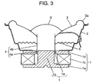
- Fig. 3 is a sectional view of a speaker
- Fig. 4 is a perspective exploded view of a voice coil assembling jig used when assembling the same
- Fig. 5 is a sectional view explaining the assembling process of the voice coil.
- Magnetic circuit 1 is composed of lower plate 1a having center pole 1b, magnet 1c coupled on lower plate 1a, and upper plate 1d coupled on magnet 1c. Magnetic circuit 1 has magnetic gap 1e between upper plate 1d and center pole 1b.
- Frame 2 is coupled to upper plate 1d.
- Diaphragm 3 is coupled to frame 2 by way of edge 3a formed on the outer circumference.
- Voice coil 4 is composed of coil 4a and bobbin 4b. Coil 4a is inserted in magnetic gap 1e, and the internal circumference of diaphragm 3 is coupled to a specified position of bobbin 4b.
- the outer circumference of damper 5 is coupled to frame 4, and its inner circumference is coupled to bobbin 4b. In this constitution, voice coil 4 is supported movably up and down.
- a conventional voice coil insertion jig disclosed in Japanese Laid-open Utility Model No. 57-160292 is explained by referring to Fig. 4 and Fig. 5.
- the conventional voice coil insertion jig is composed of jig main body 11, gauge tube 12, slit 13, and spring 14.
- Spring 14 is assembled into the inside of jig main body 11, and generates a force for opening slit 13.
- the insertion jig is inserted into bobbin 4b while closing slit 13, and after positioning, voice coil 4 is fixed by the pressure of spring 14.
- the voice coil is inserted into center pole 1b of magnetic circuit 1, that is, voice coil 4 is inserted into magnetic gap 1e.
- the position of voice coil 4 in the radial direction is defined. In this state, frame 2 is adhered and coupled to magnetic circuit 1.
- the voice coil insertion jig is required to have a high precision for positioning voice coil 4.
- magnetic gap 1e is required to be much narrower.
- the voice coil insertion jig of the invention comprises the following:
- a manufacturing method of a speaker of the invention uses the voice coil insertion jig composed as shown above, and comprises the steps of:
- the speaker of the invention is manufactured in this manufacturing method using the voice coil insertion jig composed as described above.
- Fig. 1A is a top view of a preferred embodiment of voice coil insertion jig
- Fig. 1B is a sectional view of A-O-B side in Fig. 1A
- Fig. 1C is a bottom view of the same.
- Voice coil insertion jig 20 is composed of base 20a, hollow cylindrical insertion part- 20b provided in its lower part, plurality of moving pieces 20c, and central boss 20d.
- Plurality of moving pieces 20c are provided integrally in the upper part of base 20a, being apart from each other, and the outer circumference is formed as an arc of a nearly same circumference.
- the diameter in the upper parts of plurality of moving pieces 20c is constant, and the diameter is smaller in the lower parts, that is, a slope is provided.
- Central boss 20d disposed apart from moving pieces 20c is formed so as to extend upward from the center of base 20a. The outer circumference is opposite to plurality of moving pieces 20c across a specified gap.
- Moving piece 20c has horizontal slit 20e at its lower outer side. Moving pieces 20c formed integrally in base 20a are separated by vertical slit 20f.
- Slit 20f is formed for reducing the outside diameter formed by moving pieces 20c when inserting voice coil insertion jig 20 into voice coil 4, or when extracting voice coil insertion jig 20 from voice coil 4. Therefore, the width of slit 20f is not particularly defined as far as moving pieces 20c can be inclined for inserting and extracting process (it is further preferred to set the slit width to such an extent that moving pieces 20c may not be inclined over the limit of elasticity for the sake of inserting and extracting process).
- Diameter d1 of outer circumference of base 20a and insertion part 20b, and diameter d2 formed by upper parts of moving pieces 20c in ordinary state are in the relation of d2 > d1.
- the diameter of outer circumference formed by the lowest end parts of the outer side of moving pieces 20c is set nearly at d1, and this d1 is set to be equal to the inner circumference of voice coil 4.
- moving pieces 20c are polygonal (tetragonal in the preferred embodiment) at the inner wall side, and its the apex, vertical slit 20f is formed as stated above.
- the slit width represents the interval of mutually opposing sides of moving pieces 20c.
- Central boss 20d is formed longer than moving pieces 20c, and it is used as a knob in the working process.
- Magnetic gap 1e between voice coil 4 and magnetic circuit 1 is assured by the thickness of insertion part 20b.
- the outer circumference of center pole 1b of magnetic circuit 1 and the inner circumference of insertion part 20b are nearly equal, and only a slight allowance for insertion during assembling process is provided, and the interval between the outer circumference of center pole 1b and voice coil 4 is assured by the thickness of insertion part 20b, and hence an interval between upper plate 1d and voice coil 4 is also assured.
- voice coil insertion jig 20 By pushing moving pieces 20c of voice coil insertion jig 20 to the inner side to deform within an elastic deforming range, voice coil insertion jig 20 is inserted into voice coil 4. After inserting up to a specified position, the inward pushing force applied to moving pieces 20c is released. As a result, moving pieces 20c elastically contact with the inner side of voice coil 4 in the restoring process. Thus, voice coil 4 is held in voice coil insertion jig 20.
- insertion part 20b is fitted into center pole 1b of magnetic circuit 1 preliminarily adhered and coupled to frame 2, and inserted into magnetic gap 1e.
- damper 5 and diaphragm 3 are adhered to frame 2 and coil bobbin 4b as shown in Fig. 3. Then, with moving pieces 20c being pushed to the central boss side, insertion jig 20 is pulled out. Finally, dust cap 6 is adhered to diaphragm 3.
- voice coil insertion jig 20 of the preferred embodiment positioning and fixing of voice coil 4, and handling when assembling the speaker can be done easily by using moving pieces 20c and central boss 20d, so that the working efficiency can be enhanced.
- insertion part 20b does not have slit 13 as in the prior art, but is a hollow tube, deformation of voice coil 4 can be prevented.
- magnetic gap 1e depends only on the thickness of this insertion part 20b, so that magnetic gap 1e can be assured stably. Hence, magnetic gap 1e can be narrowed, and the magnetic efficiency is enhanced and higher output is realized, while the magnetic circuit is reduced in size and the weight of the speaker can be also reduced.
- a speaker having damper 5 is explained, but it can be similarly applied to a speaker without damper.
- center pin 20g is provided in insertion part 20b. Center pin 20g is formed downward in the center of base 20a. In the center of center pole 1b, a hole (not shown) for inserting center pin 20g is formed. In the manufacturing process, by inserting center pin 20g into the hole formed in center pole 1b, voice coil 4 is positioned.
- voice coil 4 As a result, same as in preferred embodiment 1, it is not required to position voice coil 4 by defining the outer circumference of center pole 1b same as the diameter of inner circumference of insertion part 20b as much as possible, and by inserting center pin 20g, it is easier to position voice coil 4 than in preferred embodiment 1, and also voice coil 4 can be positioned without depending-on the diameter of center pole 1b, so that the jig can be managed easily without preparing insertion jig 20 for the portion of difference in outside diameter of center pole 1b.
- the invention presents a voice coil insertion jig capable of assembling a speaker at excellent working efficiency and high precision without deforming the voice coil, a manufacturing method using the same, and a speaker manufactured by this method.
Landscapes
- Engineering & Computer Science (AREA)
- Physics & Mathematics (AREA)
- Acoustics & Sound (AREA)
- Signal Processing (AREA)
- Manufacturing & Machinery (AREA)
- Audible-Bandwidth Dynamoelectric Transducers Other Than Pickups (AREA)
Abstract
Description
Claims (16)
- A voice coil insertion jig comprising:wherein the plurality of moving pieces elastically contact with and hold the voice coil.a base;a hollow cylindrical insertion part provided integrally in the lower part of the base;a plurality of moving pieces provided integrally in the upper part of the base, the outside diameter being formed the plurality of moving pieces being larger than the outside diameter of the insertion part; anda central boss provided above the center of the base, being apart from the moving pieces,
- The voice coil insertion jig of claim 1,
wherein the plurality of moving pieces contact adjacently to each other by way of a slit formed in a direction perpendicular to the base, and
each one of the plurality of moving pieces has a horizontal slit on the outer circumference of the base side. - The voice coil insertion jig of claim 1, further comprising:a center pin formed in the lower center of the base, projecting downward.
- The voice coil insertion jig of claim 1,
wherein the central boss is longer than the plurality of moving pieces. - A manufacturing method of a speaker using the voice coil insertion jig as set forth in claim 1 comprising the steps of:a) deforming a plurality of moving pieces elastically to the central boss side, and inserting into a voice coil;b) restoring the elastic deformation, and holding the voice coil in a voice coil insertion jig;c) inserting the voice coil insertion jig holding the voice coil into a magnetic gap forming a magnetic circuit;d) adhering the inner circumference of a diaphragm to the voice coil, and adhering the outer circumference of the diaphragm to a frame; ande) deforming the plurality of moving pieces elastically to the central boss side, and extracting the voice coil insertion jig from the magnetic gap.
- A speaker manufactured in the manufacturing method as set forth in claim 5.
- A voice coil insertion jig comprising:wherein the plurality of moving pieces elastically contact with and hold the voice coil.a base;an insertion part for fitting a center pole of a hollow cylindrical magnetic circuit provided integrally in the lower part of the base;a plurality of moving pieces provided integrally in the upper part of the base, the outside diameter being formed the plurality of moving pieces being larger than the outside diameter of the insertion part; anda central boss provided above the center of the base, being apart from the moving pieces,
- The voice coil insertion jig of claim 7,
wherein the plurality of moving pieces contact adjacently to each other by way of a slit formed in a direction perpendicular to the base, and
each one of the plurality of moving pieces has a horizontal slit on the outer circumference of the base side. - The voice coil insertion jig of claim 7,
wherein the central boss is longer than the plurality of moving pieces. - A manufacturing method of a speaker using the voice coil insertion jig as set forth in claim 7 comprising the steps of:a) deforming a plurality of moving pieces elastically to the central boss side, and inserting into a voice coil;b) restoring the elastic deformation, and holding the voice coil in a voice coil insertion jig;c) fitting an insertion part of the voice coil insertion jig holding the voice coil into a center pole of a magnetic circuit, and placing this insertion part into a magnetic gap;d) adhering the inner circumference of a diaphragm to the voice coil, and adhering the outer circumference of the diaphragm to a frame; ande) deforming the plurality of moving pieces elastically to the central boss side, and extracting the voice coil insertion jig from the magnetic gap.
- A speaker manufactured in the manufacturing method as set forth in claim 10.
- A voice coil insertion jig comprising:wherein the plurality of moving pieces elastically contact with and hold the voice coil.a base;a center pin formed in the lower center of the base, projecting downward;a hollow cylindrical insertion part provided integrally in the lower part of the base;a plurality of moving pieces provided integrally in the upper part of the base, the outside diameter being formed the plurality of moving pieces being larger than the outside diameter of the insertion part; anda boss forming the center pin formed in the lower center of the base, projecting downward, provided above the center of the base, being apart from the moving pieces,
- The voice coil insertion jig of claim 12,
wherein the plurality of moving pieces contact adjacently to each other by way of a slit formed in a direction perpendicular to the base, and
each one of the plurality of moving pieces has a horizontal slit on the outer circumference of the base side. - The voice coil insertion jig of claim 12,
wherein the central boss is longer than the plurality of moving pieces. - A manufacturing method of a speaker using the voice coil insertion jig as set forth in claim 12-comprising the steps of:a) deforming a plurality of moving pieces elastically to the central boss side, and inserting into a voice coil;b) restoring the elastic deformation, and holding the voice coil in a voice coil insertion jig;c) inserting the voice coil insertion jig holding the voice coil into a hole having a center pin provided in a center pole of a magnetic circuit, and inserting the voice coil insertion jig into a magnetic gap formed by the magnetic circuit;d) adhering the inner circumference of a diaphragm to the voice coil, and adhering the outer circumference of the diaphragm to a frame; ande) deforming the plurality of moving pieces elastically to the central boss side, and extracting the voice coil insertion jig from the magnetic gap.
- A speaker manufactured in the manufacturing method as set forth in claim 15.
Applications Claiming Priority (3)
| Application Number | Priority Date | Filing Date | Title |
|---|---|---|---|
| JP2002351069 | 2002-12-03 | ||
| JP2002351069A JP3843939B2 (en) | 2002-12-03 | 2002-12-03 | Voice coil insertion jig, speaker manufacturing method using the jig, and speaker manufactured using the jig |
| PCT/JP2003/015125 WO2004052051A1 (en) | 2002-12-03 | 2003-11-27 | Voice coil insertion jig, speaker producing method using the jig, and speaker produced by using the jig |
Publications (2)
| Publication Number | Publication Date |
|---|---|
| EP1469704A1 true EP1469704A1 (en) | 2004-10-20 |
| EP1469704A4 EP1469704A4 (en) | 2008-05-28 |
Family
ID=32463132
Family Applications (1)
| Application Number | Title | Priority Date | Filing Date |
|---|---|---|---|
| EP03812313A Withdrawn EP1469704A4 (en) | 2002-12-03 | 2003-11-27 | ASSEMBLY FOR INSERTING A MOBILE COIL, METHOD FOR PRODUCING A SPEAKER USING THE ASSEMBLY, AND SPEAKER PRODUCED USING THE SAME |
Country Status (6)
| Country | Link |
|---|---|
| US (1) | US7350287B2 (en) |
| EP (1) | EP1469704A4 (en) |
| JP (1) | JP3843939B2 (en) |
| KR (1) | KR100669100B1 (en) |
| CN (1) | CN100566457C (en) |
| WO (1) | WO2004052051A1 (en) |
Families Citing this family (17)
| Publication number | Priority date | Publication date | Assignee | Title |
|---|---|---|---|---|
| US7780715B2 (en) | 2004-03-04 | 2010-08-24 | Y Med, Inc. | Vessel treatment devices |
| US7766951B2 (en) | 2004-03-04 | 2010-08-03 | Y Med, Inc. | Vessel treatment devices |
| US9050437B2 (en) | 2004-03-04 | 2015-06-09 | YMED, Inc. | Positioning device for ostial lesions |
| US20070260224A1 (en) * | 2006-03-09 | 2007-11-08 | Abbott Laboratories | Flexible catheter tip having a shaped head |
| US8167929B2 (en) * | 2006-03-09 | 2012-05-01 | Abbott Laboratories | System and method for delivering a stent to a bifurcated vessel |
| US7901378B2 (en) * | 2006-05-11 | 2011-03-08 | Y-Med, Inc. | Systems and methods for treating a vessel using focused force |
| US8486025B2 (en) | 2006-05-11 | 2013-07-16 | Ronald J. Solar | Systems and methods for treating a vessel using focused force |
| KR100937835B1 (en) * | 2007-10-04 | 2010-01-21 | 주식회사 이엠텍 | Pretreatment device of acoustic transducer |
| JP2011211577A (en) * | 2010-03-30 | 2011-10-20 | Panasonic Corp | Manufacturing method for speaker |
| US9402754B2 (en) | 2010-05-18 | 2016-08-02 | Abbott Cardiovascular Systems, Inc. | Expandable endoprostheses, systems, and methods for treating a bifurcated lumen |
| CN117098056A (en) * | 2015-12-08 | 2023-11-21 | 捷普有限公司 | Devices, systems and methods for automated speaker assembly |
| CN105828270A (en) * | 2016-04-20 | 2016-08-03 | 梧州恒声电子科技有限公司 | Analog gauge clamp of loudspeaker |
| KR101635347B1 (en) * | 2016-06-01 | 2016-07-01 | 김정화 | Jig apparatus for assembling coil speaker |
| US10349180B2 (en) * | 2017-01-03 | 2019-07-09 | Sound Sources Technology, Inc. | Shallow sub woofer |
| US10375495B2 (en) * | 2017-03-29 | 2019-08-06 | Bose Corporation | Systems and methods for assembling an electro-acoustic transducer including a miniature voice coil |
| US10425756B2 (en) | 2017-03-29 | 2019-09-24 | Bose Corporation | Systems and methods for assembling an electro-acoustic transducer including a miniature voice coil |
| CN114536247B (en) * | 2022-02-28 | 2024-02-02 | 歌尔股份有限公司 | Product side pushing and positioning mechanism |
Family Cites Families (10)
| Publication number | Priority date | Publication date | Assignee | Title |
|---|---|---|---|---|
| JPS56125194A (en) | 1980-03-08 | 1981-10-01 | Nippon Gakki Seizo Kk | Manufacture for electroacoustic converter |
| US4472604A (en) * | 1980-03-08 | 1984-09-18 | Nippon Gakki Seizo Kabushiki Kaisha | Planar type electro-acoustic transducer and process for manufacturing same |
| US4312118A (en) * | 1980-03-28 | 1982-01-26 | Cts Corporation | Method for producing speaker construction |
| JPS57160292A (en) | 1981-03-27 | 1982-10-02 | Reader Denshi Kk | Vectorscope |
| JPH0667036B2 (en) | 1984-10-31 | 1994-08-24 | ソニー株式会社 | Speaker manufacturing method |
| JPS61232797A (en) * | 1985-04-05 | 1986-10-17 | Onkyo Corp | Assembly method of electrodynamic electroacoustic transducer |
| JP2860225B2 (en) * | 1993-04-09 | 1999-02-24 | 株式会社ケンウッド | Speaker structure and method of assembling the same |
| DE19711592A1 (en) | 1997-03-20 | 1998-09-24 | Nokia Deutschland Gmbh | Voice coil assembly and method for making it |
| JP3569413B2 (en) * | 1997-03-25 | 2004-09-22 | パイオニア株式会社 | Speaker device and method of manufacturing speaker device |
| JP2001045599A (en) | 1999-07-30 | 2001-02-16 | Fujitsu Ten Ltd | Voice coil holder, voice coil bobbin and speaker assembling method |
-
2002
- 2002-12-03 JP JP2002351069A patent/JP3843939B2/en not_active Expired - Fee Related
-
2003
- 2003-11-27 CN CNB2003801002644A patent/CN100566457C/en not_active Expired - Fee Related
- 2003-11-27 US US10/501,468 patent/US7350287B2/en not_active Expired - Fee Related
- 2003-11-27 EP EP03812313A patent/EP1469704A4/en not_active Withdrawn
- 2003-11-27 KR KR1020047014671A patent/KR100669100B1/en not_active Expired - Fee Related
- 2003-11-27 WO PCT/JP2003/015125 patent/WO2004052051A1/en not_active Ceased
Also Published As
| Publication number | Publication date |
|---|---|
| CN1692678A (en) | 2005-11-02 |
| WO2004052051A1 (en) | 2004-06-17 |
| CN100566457C (en) | 2009-12-02 |
| US20050084130A1 (en) | 2005-04-21 |
| JP2004186950A (en) | 2004-07-02 |
| KR20040111420A (en) | 2004-12-31 |
| JP3843939B2 (en) | 2006-11-08 |
| KR100669100B1 (en) | 2007-01-15 |
| US7350287B2 (en) | 2008-04-01 |
| EP1469704A4 (en) | 2008-05-28 |
Similar Documents
| Publication | Publication Date | Title |
|---|---|---|
| EP1469704A1 (en) | Voice coil insertion jig, speaker producing method using the jig, and speaker produced by using the jig | |
| US20040218778A1 (en) | Loudspeaker suspension for achieving very long excursion | |
| EP2262281B1 (en) | Speaker | |
| US8315421B2 (en) | Loudspeaker having an interlocking magnet structure | |
| JP3177758B2 (en) | Speaker and method of manufacturing the same | |
| EP2566192B1 (en) | Ultra-slim speaker unit capable of improving low-pitched sound characteristic and sound pressure | |
| US20030081807A1 (en) | Speaker and method for manufacturing the speaker | |
| JP3875150B2 (en) | Electroacoustic transducer and manufacturing method thereof | |
| EP1696697B1 (en) | Loudspeaker | |
| JPH09275599A (en) | Electroacoustic transducer | |
| KR100478985B1 (en) | Electronic sound transducer | |
| KR101136019B1 (en) | Magnetic circuit for microspeaker and microspeaker using the magnetic circuit | |
| US7899202B2 (en) | Loudspeaker with cone-coupled damper | |
| EP0083174A1 (en) | Electro-acoustic transducers | |
| US7062062B2 (en) | Electromagnetic sound producing device | |
| KR101238567B1 (en) | The speaker unit improved structure and function for the slim tv | |
| US7285236B2 (en) | Injection method of inserting spring into multifunctional actuator | |
| US20050035512A1 (en) | Spring mechanism and cell contact mechanism for small electronic device | |
| JP3427260B2 (en) | Speaker | |
| CN216057482U (en) | Miniature loudspeaker | |
| KR100992512B1 (en) | Mini speaker | |
| KR20020003154A (en) | oval speaker | |
| JP3427263B2 (en) | Loudspeaker and manufacturing method thereof | |
| JPH065297U (en) | Dome type diaphragm | |
| KR20050000139A (en) | Multiple actuator |
Legal Events
| Date | Code | Title | Description |
|---|---|---|---|
| PUAI | Public reference made under article 153(3) epc to a published international application that has entered the european phase |
Free format text: ORIGINAL CODE: 0009012 |
|
| 17P | Request for examination filed |
Effective date: 20040714 |
|
| AK | Designated contracting states |
Kind code of ref document: A1 Designated state(s): AT BE BG CH CY CZ DE DK EE ES FI FR GB GR HU IE IT LI LU MC NL PT RO SE SI SK TR |
|
| RBV | Designated contracting states (corrected) |
Designated state(s): DE FR GB |
|
| A4 | Supplementary search report drawn up and despatched |
Effective date: 20080429 |
|
| RAP1 | Party data changed (applicant data changed or rights of an application transferred) |
Owner name: PANASONIC CORPORATION |
|
| 17Q | First examination report despatched |
Effective date: 20090126 |
|
| STAA | Information on the status of an ep patent application or granted ep patent |
Free format text: STATUS: THE APPLICATION IS DEEMED TO BE WITHDRAWN |
|
| 18D | Application deemed to be withdrawn |
Effective date: 20120328 |