EP0083174A1 - Electro-acoustic transducers - Google Patents
Electro-acoustic transducers Download PDFInfo
- Publication number
- EP0083174A1 EP0083174A1 EP82306679A EP82306679A EP0083174A1 EP 0083174 A1 EP0083174 A1 EP 0083174A1 EP 82306679 A EP82306679 A EP 82306679A EP 82306679 A EP82306679 A EP 82306679A EP 0083174 A1 EP0083174 A1 EP 0083174A1
- Authority
- EP
- European Patent Office
- Prior art keywords
- housing
- transducer
- coil assembly
- annular
- magnet
- Prior art date
- Legal status (The legal status is an assumption and is not a legal conclusion. Google has not performed a legal analysis and makes no representation as to the accuracy of the status listed.)
- Granted
Links
Images


Classifications
-
- H—ELECTRICITY
- H04—ELECTRIC COMMUNICATION TECHNIQUE
- H04R—LOUDSPEAKERS, MICROPHONES, GRAMOPHONE PICK-UPS OR LIKE ACOUSTIC ELECTROMECHANICAL TRANSDUCERS; DEAF-AID SETS; PUBLIC ADDRESS SYSTEMS
- H04R31/00—Apparatus or processes specially adapted for the manufacture of transducers or diaphragms therefor
-
- H—ELECTRICITY
- H04—ELECTRIC COMMUNICATION TECHNIQUE
- H04R—LOUDSPEAKERS, MICROPHONES, GRAMOPHONE PICK-UPS OR LIKE ACOUSTIC ELECTROMECHANICAL TRANSDUCERS; DEAF-AID SETS; PUBLIC ADDRESS SYSTEMS
- H04R11/00—Transducers of moving-armature or moving-core type
-
- H—ELECTRICITY
- H04—ELECTRIC COMMUNICATION TECHNIQUE
- H04R—LOUDSPEAKERS, MICROPHONES, GRAMOPHONE PICK-UPS OR LIKE ACOUSTIC ELECTROMECHANICAL TRANSDUCERS; DEAF-AID SETS; PUBLIC ADDRESS SYSTEMS
- H04R2499/00—Aspects covered by H04R or H04S not otherwise provided for in their subgroups
- H04R2499/10—General applications
- H04R2499/11—Transducers incorporated or for use in hand-held devices, e.g. mobile phones, PDA's, camera's
-
- H—ELECTRICITY
- H04—ELECTRIC COMMUNICATION TECHNIQUE
- H04R—LOUDSPEAKERS, MICROPHONES, GRAMOPHONE PICK-UPS OR LIKE ACOUSTIC ELECTROMECHANICAL TRANSDUCERS; DEAF-AID SETS; PUBLIC ADDRESS SYSTEMS
- H04R31/00—Apparatus or processes specially adapted for the manufacture of transducers or diaphragms therefor
- H04R31/006—Interconnection of transducer parts
Definitions
- This invention relates to electro-acoustic transducers and more particularly but not exclusively to those adapted to be used as telephone earpeices or microphones.
- the invention also relates to a method of manufacturing such electro acoustic transducers.
- telephone earpieces, tone callers and microphones are small, inherently sturdy, contain a small number of parts and are inexpensive.
- space within the transducer is used to the utmost advantage. It is also important that the number of joints in the magnetic circuit of the transducer are reduced to a minimum, and that the dimensions of gaps in the magnetic circuit are accurately determined and fixed during manufacture.
- an electro-acoustic transducer comprises a first housing, a permanent magnet moulded in the first housing and a coil assembly mounted in the first housing adjacent to the magnet, the first housing including a location for an armature, the location providing a predetermined clearance between the magnet, the coil assembly and the armature, and a second housing moulded around the first housing so as to be bonded thereto, the second housing forming at least a portion of the outer walls of the transducer.
- a method of making-an electro-acoustic transducer comprises the steps of moulding a first housing around a ferromagnetic member, locating a coil assembly in the first housing adjacent to the ferromagnetic member and moulding a second housing around the first housing.so as to be bonded thereto, the second housing forming at least a portion of the outer walls of the transducer.
- the transducer comprises a first plastics housing 10 which is moulded around a hard sintered metal annular ring 12 which will eventually be permanently magnetized.
- the distance A between the end 14 of the ring 12 and the face of an annular surface 16 is accurately dimensioned during the moulding process to be around 007 of an inch (see Fig.l)
- An annular coil 18 is then placed over a soft iron core 20 which is formed integrally with a circular soft iron plate 22.
- the wires from the coil are carried on a short stem 24 which fits into a slot 26 formed in the plate 22.
- the coil 18 and the integral core 20 and plate 22 are then inserted into the ring 12 and.located by the stem 24 which fits into.a slot 28 formed in the housing 10.
- Two terminals 30 and 32 are inserted into blind holes 34 and 36 and the ends of the wires from the coil connected to the terminals by suitable means, such as soldering. The terminals are then bent through 90° into the position shown in Figure 3 to relieve any strain on the coil wires and facilitate external connection.
- the housing 10 is then placed in a press which engages the surface of the plate 22 and the end 14 of the ring 12. As the press pressure is increased the soft iron plate 22 is slightly deformed to correctly seat on the end of the ring 12 and the end of the core ' 20 is aligned with the end 14 of the ring 12. A plastics cover 38 is now placed on the housing 10 covering the plate 22, the cover being provided with slots 40 and 42 through which the terminals 30 and 32 project.
- the first housing assembly is now placed on a moulding die 44 (Fig.3) on to which is clamped a second die 46.
- the second die is provided with holes 48 through which the terminals 30 and 32 project and a piston member 50 spring urged by a resilient polyurethane plug 52 contacts the cover 38 to hold the first housing assembly in position.
- a suitable housing such as the circular housing 54 is now injection moulded around the first housing assembly, the circular housing forming the outer wall of the transducer and locating the first housing by radially extending webs such as the webs 56 and 58.
- the rear face 68 of the housing 54 is also moulded to the cover 38 and to the end of the first housing 10 surrounding the cover 38.
- the cover 38 is provided with a hole 60 which aligns with a hole 62 formed in the plate 22, and during the moulding process molten plastic passes through the holes 60 and 62 into the space between the coil 18 and the ring 12.
- Molten plastic also flows in to an annular space 64 to form a circular flange 66 to lock the assembly together.
- the transducer is now completed by placing the armature 70 on the surface 16, permanently magnetising the ring 12, bonding the centre of a circular diaphragm 72 to the centre of the armature 70 and securing the outer edge of the diaphragm by a rubber 'O' ring 74 and a cover 76 which is secured on a flange formed on the housing 54.
- a membrane 78 and a clamping disc 80 is located inside the cover 76 to prevent the ingress of duct etc.
- the ring 12 is initially magnetically saturated so that the armature 70 is pulled up against the end 14 of the magnet 12 and the end of the core 20.
- the magnet 12 is then gradually demagnetized so that the armature moves away from the magnet 12 and the core 20 until the desired amplitude of movement is achieved in the diaphragm 72.
Abstract
Description
- This invention relates to electro-acoustic transducers and more particularly but not exclusively to those adapted to be used as telephone earpeices or microphones. The invention also relates to a method of manufacturing such electro acoustic transducers.
- It is desirable that telephone earpieces, tone callers and microphones are small, inherently sturdy, contain a small number of parts and are inexpensive. In order to ensure that the efficiency of a transducer is the optimum obtainable it is most important that the space within the transducer is used to the utmost advantage. It is also important that the number of joints in the magnetic circuit of the transducer are reduced to a minimum, and that the dimensions of gaps in the magnetic circuit are accurately determined and fixed during manufacture.
- It is an object of the present invention therefore to provide an electro-acoustic transducer which will meet or substantially meet these requirements.
- According to a feature of the present invention an electro-acoustic transducer comprises a first housing, a permanent magnet moulded in the first housing and a coil assembly mounted in the first housing adjacent to the magnet, the first housing including a location for an armature, the location providing a predetermined clearance between the magnet, the coil assembly and the armature, and a second housing moulded around the first housing so as to be bonded thereto, the second housing forming at least a portion of the outer walls of the transducer.
- According to a further feature of the invention a method of making-an electro-acoustic transducer comprises the steps of moulding a first housing around a ferromagnetic member, locating a coil assembly in the first housing adjacent to the ferromagnetic member and moulding a second housing around the first housing.so as to be bonded thereto, the second housing forming at least a portion of the outer walls of the transducer.
- Further features of the invention will become apparent from the following description of an embodiment of the invention given by way of example only with reference to the accompanying drawings in which:-
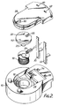
- Figure 1 is a cross-sectional view of an electro-acoustic transducer constructed in accordance with the invention,
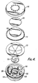
- Figure 2 is an exploded view of part of the electro-acoustic transducer,
- Figure.3 is a cross-sectional view of-the part of the electro-acoustic transducer shown in Figure 2 prior to a moulding process and,
- Figure 4 is an exploded view of the final transducer assembly.
- Referring first to Figure 2, the transducer comprises a
first plastics housing 10 which is moulded around a hard sintered metalannular ring 12 which will eventually be permanently magnetized. The distance A between theend 14 of thering 12 and the face of anannular surface 16 is accurately dimensioned during the moulding process to be around 007 of an inch (see Fig.l) Anannular coil 18 is then placed over asoft iron core 20 which is formed integrally with a circularsoft iron plate 22. The wires from the coil are carried on ashort stem 24 which fits into aslot 26 formed in theplate 22. Thecoil 18 and theintegral core 20 andplate 22 are then inserted into thering 12 and.located by thestem 24 which fits into.aslot 28 formed in thehousing 10. Twoterminals blind holes - The
housing 10 is then placed in a press which engages the surface of theplate 22 and theend 14 of thering 12. As the press pressure is increased thesoft iron plate 22 is slightly deformed to correctly seat on the end of thering 12 and the end of thecore ' 20 is aligned with theend 14 of thering 12. Aplastics cover 38 is now placed on thehousing 10 covering theplate 22, the cover being provided withslots terminals - The first housing assembly is now placed on a moulding die 44 (Fig.3) on to which is clamped a
second die 46. The second die is provided withholes 48 through which theterminals piston member 50 spring urged by aresilient polyurethane plug 52 contacts thecover 38 to hold the first housing assembly in position. - A suitable housing such as the
circular housing 54 is now injection moulded around the first housing assembly, the circular housing forming the outer wall of the transducer and locating the first housing by radially extending webs such as thewebs rear face 68 of thehousing 54 is also moulded to thecover 38 and to the end of thefirst housing 10 surrounding thecover 38. Thecover 38 is provided with ahole 60 which aligns with ahole 62 formed in theplate 22, and during the moulding process molten plastic passes through theholes coil 18 and thering 12. - Molten plastic also flows in to an
annular space 64 to form acircular flange 66 to lock the assembly together. - The transducer is now completed by placing the
armature 70 on thesurface 16, permanently magnetising thering 12, bonding the centre of acircular diaphragm 72 to the centre of thearmature 70 and securing the outer edge of the diaphragm by a rubber 'O'ring 74 and acover 76 which is secured on a flange formed on thehousing 54. Amembrane 78 and aclamping disc 80 is located inside thecover 76 to prevent the ingress of duct etc. Thering 12 is initially magnetically saturated so that thearmature 70 is pulled up against theend 14 of themagnet 12 and the end of thecore 20. Themagnet 12 is then gradually demagnetized so that the armature moves away from themagnet 12 and thecore 20 until the desired amplitude of movement is achieved in thediaphragm 72.
Claims (20)
Priority Applications (1)
| Application Number | Priority Date | Filing Date | Title |
|---|---|---|---|
| AT82306679T ATE21477T1 (en) | 1981-12-30 | 1982-12-14 | ELECTROACOUSTIC TRANSDUCERS. |
Applications Claiming Priority (2)
| Application Number | Priority Date | Filing Date | Title |
|---|---|---|---|
| GB8139109 | 1981-12-30 | ||
| GB8139109 | 1981-12-30 |
Publications (2)
| Publication Number | Publication Date |
|---|---|
| EP0083174A1 true EP0083174A1 (en) | 1983-07-06 |
| EP0083174B1 EP0083174B1 (en) | 1986-08-13 |
Family
ID=10526884
Family Applications (1)
| Application Number | Title | Priority Date | Filing Date |
|---|---|---|---|
| EP82306679A Expired EP0083174B1 (en) | 1981-12-30 | 1982-12-14 | Electro-acoustic transducers |
Country Status (13)
| Country | Link |
|---|---|
| US (1) | US4578808A (en) |
| EP (1) | EP0083174B1 (en) |
| JP (1) | JPS58189000A (en) |
| AT (1) | ATE21477T1 (en) |
| AU (1) | AU564586B2 (en) |
| CA (1) | CA1200307A (en) |
| DE (1) | DE3272633D1 (en) |
| DK (1) | DK568182A (en) |
| GB (1) | GB2113503B (en) |
| IN (1) | IN157661B (en) |
| NZ (1) | NZ202880A (en) |
| ZA (1) | ZA829234B (en) |
| ZW (1) | ZW26882A1 (en) |
Cited By (3)
| Publication number | Priority date | Publication date | Assignee | Title |
|---|---|---|---|---|
| EP0615398A1 (en) * | 1993-02-26 | 1994-09-14 | Koninklijke Philips Electronics N.V. | Electroacoustic transducer having a mask |
| EP0616483A1 (en) * | 1993-02-26 | 1994-09-21 | Koninklijke Philips Electronics N.V. | Electroacoustic transducer having a cover part |
| US6395915B1 (en) * | 1999-09-10 | 2002-05-28 | Technikrom, Inc. | Method for producing purified tocotrienols and tocopherols using liquid chromatography |
Families Citing this family (6)
| Publication number | Priority date | Publication date | Assignee | Title |
|---|---|---|---|---|
| US4626688A (en) | 1982-11-26 | 1986-12-02 | Barnes Gary T | Split energy level radiation detection |
| JP2575831B2 (en) * | 1988-07-25 | 1997-01-29 | スター精密 株式会社 | Pronunciation body |
| JP3618498B2 (en) * | 1996-12-26 | 2005-02-09 | 株式会社シチズン電子 | Surface mount electromagnetic sounding body |
| KR100332866B1 (en) * | 1999-01-28 | 2002-04-17 | 이형도 | A micro speaker and a method for manufacturing thereof |
| US20040032957A1 (en) * | 2002-08-14 | 2004-02-19 | Mansy Hansen A. | Sensors and sensor assemblies for monitoring biological sounds and electric potentials |
| US7270778B2 (en) * | 2004-03-18 | 2007-09-18 | General Electric Company | Method for attachment of a plastic probe tip to a metal component |
Citations (6)
| Publication number | Priority date | Publication date | Assignee | Title |
|---|---|---|---|---|
| US2820107A (en) * | 1954-12-22 | 1958-01-14 | Sonotonc Corp | Electro-mechanical signal transducers |
| US3242386A (en) * | 1962-12-07 | 1966-03-22 | Western Electric Co | Magnet stabilizing method and apparatus |
| CH418401A (en) * | 1962-12-13 | 1966-08-15 | Akg Akustische Kino Geraete | Electroacoustic converter |
| US3619434A (en) * | 1968-06-14 | 1971-11-09 | Western Electric Co | Method of adjusting the airgap of and finally assembling electrical transducers of the central armature receiver type |
| US4246450A (en) * | 1979-05-25 | 1981-01-20 | International Telephone And Telegraph Corporation | Telephone transducer assembly and method of making same |
| GB2062405A (en) * | 1979-10-20 | 1981-05-20 | Plessey Co Ltd | Acoustic transducer production for telephones |
Family Cites Families (4)
| Publication number | Priority date | Publication date | Assignee | Title |
|---|---|---|---|---|
| US3324253A (en) * | 1962-10-15 | 1967-06-06 | Matsushita Electric Ind Co Ltd | Small-sized electroacoustic transducers |
| US3497638A (en) * | 1967-03-20 | 1970-02-24 | Ltv Ling Altec Inc | Explosion-proof acoustic device |
| US4443667A (en) * | 1982-01-11 | 1984-04-17 | Bell Telephone Laboratories, Incorporated | Electromagnetic transducer |
| US4425482A (en) * | 1982-03-08 | 1984-01-10 | Western Electric Company | Ring armature electroacoustic transducer |
-
1982
- 1982-12-14 EP EP82306679A patent/EP0083174B1/en not_active Expired
- 1982-12-14 DE DE8282306679T patent/DE3272633D1/en not_active Expired
- 1982-12-14 AT AT82306679T patent/ATE21477T1/en active
- 1982-12-14 GB GB08235544A patent/GB2113503B/en not_active Expired
- 1982-12-15 ZA ZA829234A patent/ZA829234B/en unknown
- 1982-12-22 AU AU91809/82A patent/AU564586B2/en not_active Expired - Fee Related
- 1982-12-22 DK DK568182A patent/DK568182A/en not_active Application Discontinuation
- 1982-12-22 NZ NZ202880A patent/NZ202880A/en unknown
- 1982-12-24 ZW ZW268/82A patent/ZW26882A1/en unknown
- 1982-12-24 CA CA000418583A patent/CA1200307A/en not_active Expired
- 1982-12-27 JP JP57227197A patent/JPS58189000A/en active Pending
- 1982-12-30 IN IN1504/CAL/82A patent/IN157661B/en unknown
-
1983
- 1983-01-12 US US06/457,358 patent/US4578808A/en not_active Expired - Fee Related
Patent Citations (6)
| Publication number | Priority date | Publication date | Assignee | Title |
|---|---|---|---|---|
| US2820107A (en) * | 1954-12-22 | 1958-01-14 | Sonotonc Corp | Electro-mechanical signal transducers |
| US3242386A (en) * | 1962-12-07 | 1966-03-22 | Western Electric Co | Magnet stabilizing method and apparatus |
| CH418401A (en) * | 1962-12-13 | 1966-08-15 | Akg Akustische Kino Geraete | Electroacoustic converter |
| US3619434A (en) * | 1968-06-14 | 1971-11-09 | Western Electric Co | Method of adjusting the airgap of and finally assembling electrical transducers of the central armature receiver type |
| US4246450A (en) * | 1979-05-25 | 1981-01-20 | International Telephone And Telegraph Corporation | Telephone transducer assembly and method of making same |
| GB2062405A (en) * | 1979-10-20 | 1981-05-20 | Plessey Co Ltd | Acoustic transducer production for telephones |
Cited By (3)
| Publication number | Priority date | Publication date | Assignee | Title |
|---|---|---|---|---|
| EP0615398A1 (en) * | 1993-02-26 | 1994-09-14 | Koninklijke Philips Electronics N.V. | Electroacoustic transducer having a mask |
| EP0616483A1 (en) * | 1993-02-26 | 1994-09-21 | Koninklijke Philips Electronics N.V. | Electroacoustic transducer having a cover part |
| US6395915B1 (en) * | 1999-09-10 | 2002-05-28 | Technikrom, Inc. | Method for producing purified tocotrienols and tocopherols using liquid chromatography |
Also Published As
| Publication number | Publication date |
|---|---|
| ZA829234B (en) | 1983-12-28 |
| CA1200307A (en) | 1986-02-04 |
| US4578808A (en) | 1986-03-25 |
| GB2113503A (en) | 1983-08-03 |
| DK568182A (en) | 1983-07-01 |
| AU564586B2 (en) | 1987-08-20 |
| IN157661B (en) | 1986-05-17 |
| JPS58189000A (en) | 1983-11-04 |
| NZ202880A (en) | 1985-02-28 |
| EP0083174B1 (en) | 1986-08-13 |
| AU9180982A (en) | 1983-07-07 |
| GB2113503B (en) | 1985-05-09 |
| ATE21477T1 (en) | 1986-08-15 |
| ZW26882A1 (en) | 1983-09-14 |
| DE3272633D1 (en) | 1986-09-18 |
Similar Documents
| Publication | Publication Date | Title |
|---|---|---|
| US5905805A (en) | Electrodynamic transducer | |
| CN100409722C (en) | Loudspeaker and method of mfg. such loudspeaker | |
| US5195142A (en) | Piezoelectric transducer | |
| US4697283A (en) | Telephone handset with integrated flux coil | |
| US4578808A (en) | Electro-acoustic transducers | |
| EP1511356A1 (en) | Speaker | |
| JPH0738760B2 (en) | Microphone manufacturing method and microphone structure | |
| KR100429664B1 (en) | Microspeaker | |
| CA2066262A1 (en) | Piezoelectric sound generator and method of its manufacture | |
| US4608463A (en) | Electro-acoustic transducer | |
| JPH09275599A (en) | Electroacoustic transducer | |
| US4360711A (en) | Magnetic electro-acoustic transducer construction | |
| US5953437A (en) | Electroacoustic transducer | |
| EP0790752A1 (en) | Sounder | |
| JP4553278B2 (en) | Multifunctional sounding body and method for producing the same | |
| US11600435B2 (en) | Coil bobbin for a balanced armature receiver | |
| EP1241920A2 (en) | Electromagnetic sound producing device. | |
| US20070223769A1 (en) | Speaker and method making the same | |
| JP3840727B2 (en) | Speaker device and manufacturing method thereof | |
| JP3246123B2 (en) | Sounder and method of manufacturing the same | |
| JP2004282761A (en) | Acoustic transducer | |
| KR20060044203A (en) | Method for manufacturing a micro speaker and the micro speaker | |
| JPH09215091A (en) | Electromagnetic sounding body | |
| JP2568081Y2 (en) | Electromagnetic receiver | |
| JP2002218578A (en) | Multifunctional sounder and its manufacturing method |
Legal Events
| Date | Code | Title | Description |
|---|---|---|---|
| PUAI | Public reference made under article 153(3) epc to a published international application that has entered the european phase |
Free format text: ORIGINAL CODE: 0009012 |
|
| AK | Designated contracting states |
Designated state(s): AT BE CH DE FR IT LI LU NL SE |
|
| 17P | Request for examination filed |
Effective date: 19831221 |
|
| GRAA | (expected) grant |
Free format text: ORIGINAL CODE: 0009210 |
|
| AK | Designated contracting states |
Kind code of ref document: B1 Designated state(s): AT BE CH DE FR IT LI LU NL SE |
|
| REF | Corresponds to: |
Ref document number: 21477 Country of ref document: AT Date of ref document: 19860815 Kind code of ref document: T |
|
| ET | Fr: translation filed | ||
| ITF | It: translation for a ep patent filed |
Owner name: ING. C. GREGORJ S.P.A. |
|
| REF | Corresponds to: |
Ref document number: 3272633 Country of ref document: DE Date of ref document: 19860918 |
|
| PGFP | Annual fee paid to national office [announced via postgrant information from national office to epo] |
Ref country code: AT Payment date: 19861211 Year of fee payment: 5 |
|
| PG25 | Lapsed in a contracting state [announced via postgrant information from national office to epo] |
Ref country code: LU Free format text: LAPSE BECAUSE OF NON-PAYMENT OF DUE FEES Effective date: 19861231 |
|
| PGFP | Annual fee paid to national office [announced via postgrant information from national office to epo] |
Ref country code: NL Payment date: 19861231 Year of fee payment: 5 |
|
| PLBE | No opposition filed within time limit |
Free format text: ORIGINAL CODE: 0009261 |
|
| STAA | Information on the status of an ep patent application or granted ep patent |
Free format text: STATUS: NO OPPOSITION FILED WITHIN TIME LIMIT |
|
| 26N | No opposition filed | ||
| PG25 | Lapsed in a contracting state [announced via postgrant information from national office to epo] |
Ref country code: AT Effective date: 19871214 |
|
| PG25 | Lapsed in a contracting state [announced via postgrant information from national office to epo] |
Ref country code: SE Effective date: 19871215 |
|
| PG25 | Lapsed in a contracting state [announced via postgrant information from national office to epo] |
Ref country code: LI Effective date: 19871231 Ref country code: CH Effective date: 19871231 Ref country code: BE Effective date: 19871231 |
|
| BERE | Be: lapsed |
Owner name: PLESSEY OVERSEAS LTD Effective date: 19871231 |
|
| PG25 | Lapsed in a contracting state [announced via postgrant information from national office to epo] |
Ref country code: NL Effective date: 19880701 |
|
| NLV4 | Nl: lapsed or anulled due to non-payment of the annual fee | ||
| PG25 | Lapsed in a contracting state [announced via postgrant information from national office to epo] |
Ref country code: FR Free format text: LAPSE BECAUSE OF NON-PAYMENT OF DUE FEES Effective date: 19880831 |
|
| REG | Reference to a national code |
Ref country code: CH Ref legal event code: PL |
|
| PG25 | Lapsed in a contracting state [announced via postgrant information from national office to epo] |
Ref country code: DE Effective date: 19880901 |
|
| REG | Reference to a national code |
Ref country code: FR Ref legal event code: ST |
|
| EUG | Se: european patent has lapsed |
Ref document number: 82306679.0 Effective date: 19880913 |