EP1469668A2 - Print terminal, print system and storage medium - Google Patents
Print terminal, print system and storage medium Download PDFInfo
- Publication number
- EP1469668A2 EP1469668A2 EP04008907A EP04008907A EP1469668A2 EP 1469668 A2 EP1469668 A2 EP 1469668A2 EP 04008907 A EP04008907 A EP 04008907A EP 04008907 A EP04008907 A EP 04008907A EP 1469668 A2 EP1469668 A2 EP 1469668A2
- Authority
- EP
- European Patent Office
- Prior art keywords
- image
- medium
- rotation
- image data
- Prior art date
- Legal status (The legal status is an assumption and is not a legal conclusion. Google has not performed a legal analysis and makes no representation as to the accuracy of the status listed.)
- Withdrawn
Links
Images




Classifications
-
- G—PHYSICS
- G06—COMPUTING OR CALCULATING; COUNTING
- G06F—ELECTRIC DIGITAL DATA PROCESSING
- G06F3/00—Input arrangements for transferring data to be processed into a form capable of being handled by the computer; Output arrangements for transferring data from processing unit to output unit, e.g. interface arrangements
- G06F3/12—Digital output to print unit, e.g. line printer, chain printer
-
- H—ELECTRICITY
- H04—ELECTRIC COMMUNICATION TECHNIQUE
- H04N—PICTORIAL COMMUNICATION, e.g. TELEVISION
- H04N1/00—Scanning, transmission or reproduction of documents or the like, e.g. facsimile transmission; Details thereof
- H04N1/387—Composing, repositioning or otherwise geometrically modifying originals
- H04N1/3877—Image rotation
-
- H—ELECTRICITY
- H04—ELECTRIC COMMUNICATION TECHNIQUE
- H04N—PICTORIAL COMMUNICATION, e.g. TELEVISION
- H04N5/00—Details of television systems
- H04N5/76—Television signal recording
- H04N5/765—Interface circuits between an apparatus for recording and another apparatus
-
- H—ELECTRICITY
- H04—ELECTRIC COMMUNICATION TECHNIQUE
- H04N—PICTORIAL COMMUNICATION, e.g. TELEVISION
- H04N5/00—Details of television systems
- H04N5/76—Television signal recording
- H04N5/78—Television signal recording using magnetic recording
- H04N5/781—Television signal recording using magnetic recording on disks or drums
-
- H—ELECTRICITY
- H04—ELECTRIC COMMUNICATION TECHNIQUE
- H04N—PICTORIAL COMMUNICATION, e.g. TELEVISION
- H04N5/00—Details of television systems
- H04N5/76—Television signal recording
- H04N5/84—Television signal recording using optical recording
- H04N5/85—Television signal recording using optical recording on discs or drums
-
- H—ELECTRICITY
- H04—ELECTRIC COMMUNICATION TECHNIQUE
- H04N—PICTORIAL COMMUNICATION, e.g. TELEVISION
- H04N5/00—Details of television systems
- H04N5/76—Television signal recording
- H04N5/907—Television signal recording using static stores, e.g. storage tubes or semiconductor memories
Definitions
- the present invention relates to print terminals, print systems, storage media, and programs for printing image data.
- images obtained by, for example, digital still cameras and those read by scanners are rectangular in shape.
- print images the orientations of images to be actually printed
- feeding directions the orientations (feeding directions) of the print media are often adjusted to coincide with each other. Therefore, some known apparatuses are provided with functions for changing the orientations of print images and print media in applications (such as printer drivers) running on the displays of personal computers and printers.
- Japanese Unexamined Patent Application Publication No. 2003-37798 discloses a print apparatus provided with an image rotation button and a paper shift/rotation button.
- Japanese Unexamined Patent Application Publication No. 2000-78394 discloses an apparatus with an image rotation button
- Japanese Unexamined Patent Application Publication No. 11-341272 discloses an image processing method including a step of image rotation.
- Subject images obtained by, for example, a digital still camera are in vertical or horizontal orientation depending on the position of the camera at the time of shooting (when the shutter is pressed). For example, shooting of a head-to-toe picture of a standing person by using a camera in a horizontal position produces, as shown in Fig. 6A, a horizontally-oriented rectangular image in which the person's head and toes are positioned at the top and bottom, respectively (hereinafter referred to as a "first image"). On the other hand, the camera in a vertical position produces, as shown in Fig.
- a horizontally-oriented rectangular image in which the person's head and toes are positioned on the left and right, respectively hereinafter referred to as a "second image"
- the head and toes are positioned on the right and left, respectively.
- a horizontally-oriented rectangular image whose horizontal sides are longer than its vertical sides
- a vertically-oriented rectangular image whose vertical sides are longer than its horizontal sides
- the first image and the second image shown in Fig. 6A and Fig. 6B, respectively can be changed from landscape images to portrait images by 90-degree rotation of the images.
- Images obtained by, for example, a digital still camera are normally landscape images.
- Subject images are stored, as shown in Figs. 6A and 6B, depending on the position of the camera at the time of shooting.
- the orientation of a sheet serving as a print medium can be changed from portrait to landscape or from landscape to portrait.
- the orientation of the print image is changed to portrait with reference to the orientation of the print medium, or the orientation of the print medium is changed to landscape with reference to the orientation of the print image, thereby matching the orientations of both the print image and the print medium.
- the present invention is made to solve the problem described above.
- An object of the present invention to simplify the user operation in printing image data obtained by shooting with, for example, a digital still camera.
- a print terminal of the present invention includes an image-capturing unit for capturing image data, a first rotation-processing unit for rotating a print image to be used in printing the image data captured by the image-capturing unit, a second rotation-processing unit for rotating a print-medium image to change the orientation of a print medium to be used in printing the image data captured by the image-capturing unit, and a third rotation-processing unit for simultaneously rotating both the print image and the print-medium image.
- the first rotation-processing unit rotates the print image
- the second rotation-processing unit rotates the print-medium image
- the third rotation-processing unit simultaneously rotates both the print image and the print-medium image.
- Fig. 1 is a block diagram of a print system according to the embodiment of the present invention.
- the print system is composed mainly of a print terminal 1 and a printer 2.
- the print terminal 1 and the printer 2 are connected via communication tools such as a printer cable and a wireless local area network (LAN).
- Examples of the printer 2 include a color laser printer.
- the print terminal 1 is an integrated combination of a central processing unit (CPU) 3, a read-only memory (ROM) 4, a random-access memory (RAM) 5, a touch panel display 6, a hard disk drive (HDD) 7, and a memory reader 8.
- CPU central processing unit
- ROM read-only memory
- RAM random-access memory
- HDD hard disk drive
- the display 6 and the memory reader 8 may be provided as external units, integrating them in the print terminal 1 is preferable for making the entire print system compact.
- the CPU 3 controls the overall operation in the print terminal 1, according to operation programs stored (installed) in the HDD 7.
- a basic input/output system (BIOS) is written in the ROM 4.
- the BIOS is provided for the CPU 3 to control peripheral devices, such as the printer 2, the display 6, the HDD 7, and the memory reader 8, in executing the operation programs.
- the RAM 5 is a work area for the CPU 3 in executing the operation programs.
- the display 6 displays various types of information to users on the screen, while receiving operational instructions from users via a touch panel.
- the operational instructions from users may also be received via input devices such as a keyboard, mouse, stick, and buttons.
- the HDD 7 is a large-capacity memory device for storing the described operation programs, other application programs (for example, a word-processing program and an image-editing program), and various types of data (for example, image data and document data).
- the memory reader 8 reads image data recorded in the recording medium 9 such as a memory card, a floppy (registered trademark) disk, and a CD-ROM. Users of the print terminal 1 can receive print services simply by placing the portable (compact) recording medium 9 in the memory reader 8.
- the memory reader 8 is preferably capable of reading image data stored in the various types of recording medium.
- the memory reader 8 is provided with a plurality of slots corresponding to the types of recording medium and a reader for reading image data from the recording medium in the slot.
- Fig. 2 is a block diagram showing the structure of the print terminal 1, which includes functional units implemented by the CPU 3 executing the above-described operation programs.
- an image-capturing unit 10 captures image data read by the memory reader 8.
- the image-capturing unit 10 may capture image data transmitted from, for example, external devices via a communication interface.
- An image-processing unit 11 performs predetermined image processing on the image data captured by the image-capturing unit 10. Processes performed by the image-processing unit 11 include a conversion process, a first rotation process, a second rotation process, and a third rotation process.
- the conversion process the image-processing unit 11 converts the image data captured by the image-capturing unit 10 to print data (for example, data described in page-description language, that is, PDL data).
- the image-processing unit 11 rotates the print image to be used in printing the image data captured by the image-capturing unit 10.
- the image-processing unit 11 rotates the print-medium image to change the orientation of a print medium to be used in printing the image data captured by the image-capturing unit 10.
- both the print image and the print-medium image are simultaneously rotated.
- a display-controlling unit 12 controls display in the display 6.
- the display-controlling unit 12 allows the display 6 to display the image data captured by the image-capturing unit 10 as a visible image, a prepared processing menu (incorporated in the operation program), operation buttons, and the image data processed by the image-processing unit 11.
- the operation buttons are provided for users to input operational instructions via a touch panel of the display 6.
- An instruction-receiving unit 13 receives the operational instructions input by the users using the operation buttons, and transmits the received instructions to the image-capturing unit 10, the image-processing unit 11, and the display-controlling unit 12.
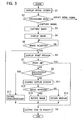
- Fig. 3 is a flowchart showing an example of processing in the print terminal 1, the processing being implemented by the CPU 3 executing the operation program.
- an initial screen appears on the display 6 according to the instruction from the display-controlling unit 12 (step S1).
- the initial screen shows, for example, a message for operator guidance and a processing menu.
- step S2 a user selects a desired menu item from the processing menu.
- the instruction-receiving unit 13 confirms the selected item (step S2).
- the confirmed menu item is "Capture Image”
- the instruction is sent to the image-capturing unit 10 for enabling it to capture image data (step S3).
- the image-capturing unit 10 captures the image data read by the memory reader 8.
- data of a plurality of images is stored in the recording medium 9, which is placed in the memory reader 8, the data is sequentially read by the memory reader 8 to be captured by the image-capturing unit 10.
- a processing menu item other than "Capture Image" is confirmed in the instruction-receiving unit 13, the remaining processing proceeds according to the confirmed menu item (the details are omitted here).
- the image data captured by the image-capturing unit 10, as described above, is sent to the display-controlling unit 12 to be displayed on the display 6 (step S4).
- the data is listed on the display 6.
- the instruction-receiving unit 13 confirms whether the user selects a print image from the image data listed on the display 6 (step S5).
- a print preview window is displayed on the display 6 according to a display instruction from the display-controlling unit 12 (step S6).
- a print-medium image and the print image are displayed in different layers. For example, a rectangular print image selected by the user is superimposed on a rectangular frame representing the outline of a sheet serving as a print medium.
- Operation buttons as well as the preview window are displayed on the display 6.
- the instruction-receiving unit 13 confirms the operation button pressed by the user (steps S7 and S8).
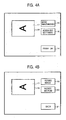
- the displayed operation buttons include a "Print OK" button 14 for printing the print image, a "Rotate Simultaneously” button 15 for simultaneously rotating both the print image and the print-medium image (third rotation process), and an "Advanced Settings” button 16 for switching to an advanced settings screen provided for individually rotating the print image and the print-medium image.
- the entire print image 17 may be displayed at a size smaller than the size of the print-medium image 18.
- the print image 17 may be enlarged or reduced to substantially the same size as the print-medium image 18.
- the image-processing unit 11 converts the image data to be printed to the print data and feeds the print data to the printer 2 (step S9).
- the image data (print data) from the image-processing unit 11 is transferred from the print terminal 1, via the described communication tools, to the printer 2 and is printed on sheets.
- the image-processing unit 11 proceeds to the third rotation process in which the print image and print-medium image displayed on the display 6 at this point are simultaneously rotated (step S10).
- the image-processing unit 11 simultaneously rotates the print image 17 and the print-medium image 18 in the same direction by 90 degrees.
- the orientation of the print image 17 is changed from landscape to portrait (or from portrait to landscape)
- the orientation of the print-medium image 18 is changed from landscape to portrait (or from portrait to landscape).
- Fig. 4A when both the print image 17 and the print-medium image 18 are in landscape orientation before the rotation process, their orientation is changed to portrait, as shown in Fig. 5, by simultaneous rotation. That is, a change of the orientation from landscape to portrait can be made in one step.
- step S6 a result of the rotation process in the image-processing unit 11 is displayed again in the preview window of the display 6 according to the display instruction from the display-controlling unit 12 (step S6).
- the image data (print data) processed by the image-processing unit 11 is fed to the printer 2 (step S9).
- the display-controlling unit 12 enables the display 6 to display the advanced settings screen according to the instruction from the instruction-receiving unit 13 (step S11).
- the advanced settings screen includes a preview window in which the print image 17 (the image including the letter "A” in the drawing) and the print-medium image 18 are displayed, a "Rotate Image” button 19 for executing the first rotation process in which the print image 17 is individually (independently) rotated, a "Rotate Medium” button 20 for executing the second rotation process in which the print-medium image 18 (sheet image) is individually (independently) rotated, and a "Back" button 21 for switching to the previous screen shown in Fig. 4A.
- step S12 When the user presses the "Rotate Image” button 19 ("Yes” in step S12), the corresponding process instruction is sent from the instruction-receiving unit 13 to the image-processing unit 11. While maintaining the orientation of the print-medium image 18, the image-processing unit 11 proceeds to the first rotation process in which the print image 17 is rotated (step S13). Here, the image-processing unit 11 rotates the print image 17 by 90 degrees or less. When the image-processing unit 11 rotates the print image 17 by 90 degrees, the orientation of the print image 17 is changed from landscape to portrait, or from portrait to landscape.
- the image-processing unit 11 When the image-processing unit 11 rotates the print image 17 by any angle from 1 to 90 degrees, the print image 17 tilts according to the angle. Therefore, the image-processing unit 11 can correct a tilt of an obtained image, such as an image obtained by shooting with a digital camera and a document image read by a scanner, by rotating the print image 17 according to the degree of the tilt. The tilt of the print image 17 from the print-medium image 18, in the preview window, can be properly handled by trimming the print image 17.
- the image-processing unit 11 proceeds to the second rotation process in which the print-medium image 18 is rotated (step S14).
- the image-processing unit 11 rotates the print-medium image 18 by 90 degrees.
- the orientation of the print-medium image 18 is changed from landscape to portrait, or from portrait to landscape.
- step S6 After the rotation of the print image 17 in step S13 or the rotation of the print-medium image 18 in step S14, the results of the rotation processes are displayed again in the preview window of the display 6 according to the display instruction from the display-controlling unit 12 (step S6).
- step S9 When the user presses the "Print OK" button 14 on the display 6, the image data (print data) processed by the image-processing unit 11 is fed to the printer 2 (step S9).
- the image-processing unit 11 simultaneously rotates both print images and print-media images.
- the user operation in printing image data obtained by shooting with, for example, a digital still camera can be simplified.
- an image data is obtained by shooting with a digital still camera in a vertical position.
- the print terminal 1 with excellent usability can thus be provided to users of print services.
- the present invention can be provided as a computer-readable storage medium (for example, a floppy (registered trademark) disk and CD-ROM) storing an operation program to be executed by the CPU 3.
- the program stored in the storage medium implements an image-capturing function for capturing image data, a first rotation-processing function for rotating a print image to be used in printing the image data captured by the image-capturing function, a second rotation-processing function for rotating a print-medium image to change the orientation of a print medium to be used in printing the image data captured by the image-capturing function, and a third rotation-processing function for simultaneously rotating both the print image and the print-medium image.
- the present invention can also be provided as a program for enabling computers to implement an image-capturing function for capturing image data, a first rotation-processing function for rotating a print image to be used in printing the image data captured by the image-capturing function, a second rotation-processing function for rotating a print-medium image to change the orientation of a print medium to be used in printing the image data captured by the image-capturing function, and a third rotation-processing function for simultaneously rotating both the print image and the print-medium image.
- both the print image and the print-medium image are simultaneously rotated according to the present invention, thereby simplifying the user operation in printing an image data obtained by shooting with, for example, a digital still camera.
Landscapes
- Engineering & Computer Science (AREA)
- Multimedia (AREA)
- Signal Processing (AREA)
- Theoretical Computer Science (AREA)
- Human Computer Interaction (AREA)
- Physics & Mathematics (AREA)
- General Engineering & Computer Science (AREA)
- General Physics & Mathematics (AREA)
- Editing Of Facsimile Originals (AREA)
- Image Processing (AREA)
- Studio Devices (AREA)
Abstract
Description
Claims (7)
- A print terminal comprising:an image-capturing unit for capturing image data;a first rotation-processing unit for rotating a print image to be used in printing the image data captured by the image-capturing unit;a second rotation-processing unit for rotating a print-medium image to change the orientation of a print medium to be used in printing the image data captured by the image-capturing unit; anda third rotation-processing unit for simultaneously rotating both the print image and the print-medium image.
- The print terminal according to Claim 1, wherein the third rotation-processing unit rotates the print image and the print-medium image by 90 degrees.
- The print terminal according to Claim 1, wherein the first rotation-processing unit rotates the print image by 90 degrees or less.
- The print terminal according to Claim 1, further comprising a reader for reading the image data from a recording medium, wherein the image-capturing unit captures the image data read by the reader.
- A print system comprising:a print terminal includingan image-capturing unit for capturing image data;a first rotation-processing unit for rotating a print image to be used in printing the image data captured by the image-capturing unit;a second rotation-processing unit for rotating a print-medium image to change the orientation of a print medium to be used in printing the image data captured by the image-capturing unit; anda third rotation-processing unit for simultaneously rotating both the print image and the print-medium image; anda printer for printing the image data processed by the print terminal on the print medium.
- A computer-readable storage medium storing a program for implementing the functions comprising:an image-capturing function for capturing image data;a first rotation-processing function for rotating a print image to be used in printing the image data captured by the image-capturing function;a second rotation-processing function for rotating a print-medium image to change the orientation of a print medium to be used in printing the image data captured by the image-capturing function; anda third rotation-processing function for simultaneously rotating both the print image and the print-medium image.
- A program for enabling computers to implement the functions comprising:an image-capturing function for capturing image data;a first rotation-processing function for rotating a print image to be used in printing the image data captured by the image-capturing function;a second rotation-processing function for rotating a print-medium image to change the orientation of a print medium to be used in printing the image data captured by the image-capturing function; anda third rotation-processing function for simultaneously rotating both the print image and the print-medium image.
Applications Claiming Priority (2)
| Application Number | Priority Date | Filing Date | Title |
|---|---|---|---|
| JP2003109779 | 2003-04-15 | ||
| JP2003109779A JP2004320277A (en) | 2003-04-15 | 2003-04-15 | Printing terminal, printing system, storage medium, and program |
Publications (2)
| Publication Number | Publication Date |
|---|---|
| EP1469668A2 true EP1469668A2 (en) | 2004-10-20 |
| EP1469668A3 EP1469668A3 (en) | 2006-02-01 |
Family
ID=32906003
Family Applications (1)
| Application Number | Title | Priority Date | Filing Date |
|---|---|---|---|
| EP04008907A Withdrawn EP1469668A3 (en) | 2003-04-15 | 2004-04-14 | Print terminal, print system and storage medium |
Country Status (5)
| Country | Link |
|---|---|
| US (1) | US8269988B2 (en) |
| EP (1) | EP1469668A3 (en) |
| JP (1) | JP2004320277A (en) |
| KR (1) | KR20040090477A (en) |
| CN (1) | CN1551612A (en) |
Cited By (3)
| Publication number | Priority date | Publication date | Assignee | Title |
|---|---|---|---|---|
| EP1841199A1 (en) * | 2006-03-30 | 2007-10-03 | Murata Kikai Kabushiki Kaisha | Scanner control device and scanner device |
| CN102736871A (en) * | 2011-03-31 | 2012-10-17 | 兄弟工业株式会社 | Mobile terminal and control method thereof |
| EP2416239A3 (en) * | 2010-08-06 | 2013-07-17 | Brother Kogyo Kabushiki Kaisha | Controlling device mounted on portable type terminal device |
Families Citing this family (12)
| Publication number | Priority date | Publication date | Assignee | Title |
|---|---|---|---|---|
| JP4468120B2 (en) * | 2004-09-14 | 2010-05-26 | キヤノン株式会社 | Image supply device, method for controlling the device, program thereof, and storage medium |
| JP4657743B2 (en) | 2005-01-28 | 2011-03-23 | 株式会社リコー | Printing system, printing apparatus, printing system control method, printing apparatus control method, program, and computer-readable storage medium |
| US20070211264A1 (en) * | 2006-03-09 | 2007-09-13 | Kabushiki Kaisha Toshiba | Image forming apparatus |
| JP2007249658A (en) * | 2006-03-16 | 2007-09-27 | Sony Corp | Product generation terminal device, product generation method, program |
| US20080292329A1 (en) * | 2007-05-25 | 2008-11-27 | Kabushiki Kaisha Toshiba | Driver apparatus, sheet arrangement management method, sheet arrangement management program |
| JP4572248B2 (en) | 2008-06-23 | 2010-11-04 | シャープ株式会社 | Image processing apparatus, image forming apparatus, image processing method, control program, and recording medium |
| JP4651704B2 (en) * | 2008-11-14 | 2011-03-16 | シャープ株式会社 | Image processing device |
| US9639787B2 (en) | 2010-03-11 | 2017-05-02 | Apple Inc. | Print orientation of documents based on device sensor output |
| US20130188064A1 (en) * | 2010-09-22 | 2013-07-25 | Takayuki Sakanaba | Photographing apparatus, image transfer method, and program |
| JP5500128B2 (en) * | 2011-07-14 | 2014-05-21 | コニカミノルタ株式会社 | Application linkage system and application linkage method |
| US9280804B2 (en) * | 2012-11-16 | 2016-03-08 | Google Inc. | Rotation of an image based on image content to correct image orientation |
| CN105589666A (en) * | 2014-11-13 | 2016-05-18 | 王者蓝 | Method for printing with template based on original content of paper |
Citations (2)
| Publication number | Priority date | Publication date | Assignee | Title |
|---|---|---|---|---|
| US5301036A (en) * | 1992-04-06 | 1994-04-05 | Xerox Corporation | Image orientation control |
| US6281872B1 (en) * | 1998-04-09 | 2001-08-28 | Hewlett-Packard Company | Rotation of an image implementing an independent mirror attribute |
Family Cites Families (18)
| Publication number | Priority date | Publication date | Assignee | Title |
|---|---|---|---|---|
| DE3778957D1 (en) * | 1986-02-03 | 1992-06-17 | Canon Kk | IMAGE RECORDING DEVICE. |
| JP3251959B2 (en) * | 1991-10-17 | 2002-01-28 | 株式会社リコー | Image forming device |
| JP3630705B2 (en) * | 1993-08-02 | 2005-03-23 | コニカミノルタビジネステクノロジーズ株式会社 | Digital copying machine |
| JP3808923B2 (en) * | 1995-11-27 | 2006-08-16 | 株式会社東芝 | Information processing device |
| JPH09197549A (en) * | 1996-01-17 | 1997-07-31 | Fuji Photo Film Co Ltd | Control method for microfilm scanner |
| JPH11341272A (en) | 1998-05-22 | 1999-12-10 | Noritsu Koki Co Ltd | Image processing apparatus and image processing method |
| US6466231B1 (en) * | 1998-08-07 | 2002-10-15 | Hewlett-Packard Company | Appliance and method of using same for capturing images |
| JP2000201261A (en) * | 1998-10-28 | 2000-07-18 | Fujitsu Ltd | Image reading device |
| JP2000151977A (en) | 1998-11-13 | 2000-05-30 | Fuji Xerox Co Ltd | Image forming device, image forming controller and image forming system |
| US6330374B1 (en) * | 1998-11-13 | 2001-12-11 | Ricoh Company, Ltd. | Image manipulation for a digital copier which operates on a block basis |
| US6400851B1 (en) * | 1999-01-28 | 2002-06-04 | Microsoft Corporation | Rotating image data |
| JP4240640B2 (en) | 1999-03-05 | 2009-03-18 | キヤノン株式会社 | Image processing method, apparatus, and storage medium |
| JP3942315B2 (en) | 1999-07-21 | 2007-07-11 | 日本電子株式会社 | High frequency power supply |
| JP2002006418A (en) | 2000-06-21 | 2002-01-09 | Noritsu Koki Co Ltd | Photo processing method and photo processing device |
| JP2002094842A (en) | 2000-09-13 | 2002-03-29 | Olympus Optical Co Ltd | Picture processor and electronic camera |
| US20020106134A1 (en) * | 2000-09-22 | 2002-08-08 | Dundon Thomas A. | Multiple-orientation image defect detection and correction |
| US7310156B2 (en) * | 2001-02-01 | 2007-12-18 | Canon Kabushiki Kaisha | Printing system, printing method, digital camera, storage medium and program for printing method, and printing control apparatus |
| JP2003037798A (en) * | 2001-07-26 | 2003-02-07 | Fuji Color Service Co Ltd | Photographing application method, photographing application program and photo print generating method |
-
2003
- 2003-04-15 JP JP2003109779A patent/JP2004320277A/en active Pending
-
2004
- 2004-04-14 US US10/823,940 patent/US8269988B2/en not_active Expired - Fee Related
- 2004-04-14 EP EP04008907A patent/EP1469668A3/en not_active Withdrawn
- 2004-04-14 KR KR1020040025700A patent/KR20040090477A/en not_active Withdrawn
- 2004-04-15 CN CNA2004100595615A patent/CN1551612A/en active Pending
Patent Citations (2)
| Publication number | Priority date | Publication date | Assignee | Title |
|---|---|---|---|---|
| US5301036A (en) * | 1992-04-06 | 1994-04-05 | Xerox Corporation | Image orientation control |
| US6281872B1 (en) * | 1998-04-09 | 2001-08-28 | Hewlett-Packard Company | Rotation of an image implementing an independent mirror attribute |
Cited By (7)
| Publication number | Priority date | Publication date | Assignee | Title |
|---|---|---|---|---|
| EP1841199A1 (en) * | 2006-03-30 | 2007-10-03 | Murata Kikai Kabushiki Kaisha | Scanner control device and scanner device |
| US7852520B2 (en) | 2006-03-30 | 2010-12-14 | Murata Kikai Kabushiki Kaisha | Scanner control device and scanner device |
| EP2416239A3 (en) * | 2010-08-06 | 2013-07-17 | Brother Kogyo Kabushiki Kaisha | Controlling device mounted on portable type terminal device |
| EP3570156B1 (en) * | 2010-08-06 | 2025-09-03 | Brother Kogyo Kabushiki Kaisha | Controlling device mounted on portable type terminal device |
| CN102736871A (en) * | 2011-03-31 | 2012-10-17 | 兄弟工业株式会社 | Mobile terminal and control method thereof |
| US8937735B2 (en) | 2011-03-31 | 2015-01-20 | Brother Kogyo Kabushiki Kaisha | Non-transitory storage medium storing image-forming-data transmitting program, mobile terminal, and control method therefor transmitting movement and orientation information of mobile terminal |
| CN102736871B (en) * | 2011-03-31 | 2015-04-01 | 兄弟工业株式会社 | Mobile terminal and control method thereof |
Also Published As
| Publication number | Publication date |
|---|---|
| US20040252318A1 (en) | 2004-12-16 |
| CN1551612A (en) | 2004-12-01 |
| JP2004320277A (en) | 2004-11-11 |
| KR20040090477A (en) | 2004-10-25 |
| EP1469668A3 (en) | 2006-02-01 |
| US8269988B2 (en) | 2012-09-18 |
Similar Documents
| Publication | Publication Date | Title |
|---|---|---|
| US8269988B2 (en) | Print terminal, print system, storage medium, and program | |
| US7224480B2 (en) | Imaging apparatus, system having imaging apparatus and printing apparatus, and control method therefor | |
| JP2004082528A (en) | Printing system | |
| JP2002016859A (en) | Digital photography system, printer used in the system, and printing method | |
| JP2001016539A (en) | Image input device and its control method, information processing device and its method, printing system, and recording medium | |
| CN108932701B (en) | Information processing apparatus, information processing method, and non-transitory storage medium | |
| US7190473B1 (en) | Printer apparatus with integrated graphical user interface and method for using the same | |
| US7804520B2 (en) | Image sending and receiving system, image sending apparatus and image receiving apparatus | |
| JPH114339A (en) | Image processing unit and photograph synthesis system | |
| KR20050054456A (en) | Printing system and printing method | |
| US20060114529A1 (en) | Terminal apparatus for transforming print image on a screen by means of print preview function and method thereof | |
| JP2003080789A (en) | Image output device | |
| JP2000299777A (en) | Image printing method and image printing system | |
| JP3697908B2 (en) | Image printing system | |
| JP4140301B2 (en) | Direct print system and direct print compatible electronic camera | |
| KR101345285B1 (en) | Printing method of photographed image and photo-printing system adapted for the same | |
| JP4856104B2 (en) | Printing terminal, printing system, storage medium, and program | |
| JP4358057B2 (en) | Computer apparatus and image processing program | |
| GB2412264A (en) | Improvements in and relating to multiple printing passes | |
| JP2000069402A (en) | ID photo output system and storage medium | |
| JP3879272B2 (en) | Interactive processing system | |
| JP5008282B2 (en) | Imaging apparatus, control method therefor, computer program, and storage medium | |
| JP2009267973A (en) | Imaging device, method for controlling same and program | |
| JPH11327864A (en) | Picture printing system | |
| JP2007196576A (en) | Printing apparatus and printing method |
Legal Events
| Date | Code | Title | Description |
|---|---|---|---|
| PUAI | Public reference made under article 153(3) epc to a published international application that has entered the european phase |
Free format text: ORIGINAL CODE: 0009012 |
|
| AK | Designated contracting states |
Kind code of ref document: A2 Designated state(s): AT BE BG CH CY CZ DE DK EE ES FI FR GB GR HU IE IT LI LU MC NL PL PT RO SE SI SK TR |
|
| AX | Request for extension of the european patent |
Extension state: AL HR LT LV MK |
|
| PUAL | Search report despatched |
Free format text: ORIGINAL CODE: 0009013 |
|
| AK | Designated contracting states |
Kind code of ref document: A3 Designated state(s): AT BE BG CH CY CZ DE DK EE ES FI FR GB GR HU IE IT LI LU MC NL PL PT RO SE SI SK TR |
|
| AX | Request for extension of the european patent |
Extension state: AL HR LT LV MK |
|
| 17P | Request for examination filed |
Effective date: 20060712 |
|
| 17Q | First examination report despatched |
Effective date: 20060829 |
|
| AKX | Designation fees paid |
Designated state(s): DE FR GB |
|
| STAA | Information on the status of an ep patent application or granted ep patent |
Free format text: STATUS: THE APPLICATION IS DEEMED TO BE WITHDRAWN |
|
| 18D | Application deemed to be withdrawn |
Effective date: 20151103 |