EP1469350A2 - Exposure apparatus and aberration correction method - Google Patents
Exposure apparatus and aberration correction method Download PDFInfo
- Publication number
- EP1469350A2 EP1469350A2 EP04251369A EP04251369A EP1469350A2 EP 1469350 A2 EP1469350 A2 EP 1469350A2 EP 04251369 A EP04251369 A EP 04251369A EP 04251369 A EP04251369 A EP 04251369A EP 1469350 A2 EP1469350 A2 EP 1469350A2
- Authority
- EP
- European Patent Office
- Prior art keywords
- air pressure
- correction
- aberration
- exposure
- barometer
- Prior art date
- Legal status (The legal status is an assumption and is not a legal conclusion. Google has not performed a legal analysis and makes no representation as to the accuracy of the status listed.)
- Withdrawn
Links
Images





Classifications
-
- G—PHYSICS
- G03—PHOTOGRAPHY; CINEMATOGRAPHY; ANALOGOUS TECHNIQUES USING WAVES OTHER THAN OPTICAL WAVES; ELECTROGRAPHY; HOLOGRAPHY
- G03F—PHOTOMECHANICAL PRODUCTION OF TEXTURED OR PATTERNED SURFACES, e.g. FOR PRINTING, FOR PROCESSING OF SEMICONDUCTOR DEVICES; MATERIALS THEREFOR; ORIGINALS THEREFOR; APPARATUS SPECIALLY ADAPTED THEREFOR
- G03F7/00—Photomechanical, e.g. photolithographic, production of textured or patterned surfaces, e.g. printing surfaces; Materials therefor, e.g. comprising photoresists; Apparatus specially adapted therefor
- G03F7/70—Microphotolithographic exposure; Apparatus therefor
- G03F7/70483—Information management; Active and passive control; Testing; Wafer monitoring, e.g. pattern monitoring
- G03F7/70591—Testing optical components
- G03F7/706—Aberration measurement
-
- G—PHYSICS
- G03—PHOTOGRAPHY; CINEMATOGRAPHY; ANALOGOUS TECHNIQUES USING WAVES OTHER THAN OPTICAL WAVES; ELECTROGRAPHY; HOLOGRAPHY
- G03F—PHOTOMECHANICAL PRODUCTION OF TEXTURED OR PATTERNED SURFACES, e.g. FOR PRINTING, FOR PROCESSING OF SEMICONDUCTOR DEVICES; MATERIALS THEREFOR; ORIGINALS THEREFOR; APPARATUS SPECIALLY ADAPTED THEREFOR
- G03F7/00—Photomechanical, e.g. photolithographic, production of textured or patterned surfaces, e.g. printing surfaces; Materials therefor, e.g. comprising photoresists; Apparatus specially adapted therefor
- G03F7/70—Microphotolithographic exposure; Apparatus therefor
- G03F7/708—Construction of apparatus, e.g. environment aspects, hygiene aspects or materials
- G03F7/70858—Environment aspects, e.g. pressure of beam-path gas, temperature
- G03F7/70883—Environment aspects, e.g. pressure of beam-path gas, temperature of optical system
-
- G—PHYSICS
- G03—PHOTOGRAPHY; CINEMATOGRAPHY; ANALOGOUS TECHNIQUES USING WAVES OTHER THAN OPTICAL WAVES; ELECTROGRAPHY; HOLOGRAPHY
- G03B—APPARATUS OR ARRANGEMENTS FOR TAKING PHOTOGRAPHS OR FOR PROJECTING OR VIEWING THEM; APPARATUS OR ARRANGEMENTS EMPLOYING ANALOGOUS TECHNIQUES USING WAVES OTHER THAN OPTICAL WAVES; ACCESSORIES THEREFOR
- G03B27/00—Photographic printing apparatus
- G03B27/32—Projection printing apparatus, e.g. enlarger, copying camera
- G03B27/52—Details
-
- G—PHYSICS
- G03—PHOTOGRAPHY; CINEMATOGRAPHY; ANALOGOUS TECHNIQUES USING WAVES OTHER THAN OPTICAL WAVES; ELECTROGRAPHY; HOLOGRAPHY
- G03F—PHOTOMECHANICAL PRODUCTION OF TEXTURED OR PATTERNED SURFACES, e.g. FOR PRINTING, FOR PROCESSING OF SEMICONDUCTOR DEVICES; MATERIALS THEREFOR; ORIGINALS THEREFOR; APPARATUS SPECIALLY ADAPTED THEREFOR
- G03F7/00—Photomechanical, e.g. photolithographic, production of textured or patterned surfaces, e.g. printing surfaces; Materials therefor, e.g. comprising photoresists; Apparatus specially adapted therefor
- G03F7/70—Microphotolithographic exposure; Apparatus therefor
- G03F7/70216—Mask projection systems
- G03F7/70258—Projection system adjustments, e.g. adjustments during exposure or alignment during assembly of projection system
-
- G—PHYSICS
- G03—PHOTOGRAPHY; CINEMATOGRAPHY; ANALOGOUS TECHNIQUES USING WAVES OTHER THAN OPTICAL WAVES; ELECTROGRAPHY; HOLOGRAPHY
- G03F—PHOTOMECHANICAL PRODUCTION OF TEXTURED OR PATTERNED SURFACES, e.g. FOR PRINTING, FOR PROCESSING OF SEMICONDUCTOR DEVICES; MATERIALS THEREFOR; ORIGINALS THEREFOR; APPARATUS SPECIALLY ADAPTED THEREFOR
- G03F7/00—Photomechanical, e.g. photolithographic, production of textured or patterned surfaces, e.g. printing surfaces; Materials therefor, e.g. comprising photoresists; Apparatus specially adapted therefor
- G03F7/70—Microphotolithographic exposure; Apparatus therefor
- G03F7/70483—Information management; Active and passive control; Testing; Wafer monitoring, e.g. pattern monitoring
- G03F7/70491—Information management, e.g. software; Active and passive control, e.g. details of controlling exposure processes or exposure tool monitoring processes
- G03F7/70516—Calibration of components of the microlithographic apparatus, e.g. light sources, addressable masks or detectors
-
- G—PHYSICS
- G03—PHOTOGRAPHY; CINEMATOGRAPHY; ANALOGOUS TECHNIQUES USING WAVES OTHER THAN OPTICAL WAVES; ELECTROGRAPHY; HOLOGRAPHY
- G03F—PHOTOMECHANICAL PRODUCTION OF TEXTURED OR PATTERNED SURFACES, e.g. FOR PRINTING, FOR PROCESSING OF SEMICONDUCTOR DEVICES; MATERIALS THEREFOR; ORIGINALS THEREFOR; APPARATUS SPECIALLY ADAPTED THEREFOR
- G03F7/00—Photomechanical, e.g. photolithographic, production of textured or patterned surfaces, e.g. printing surfaces; Materials therefor, e.g. comprising photoresists; Apparatus specially adapted therefor
- G03F7/70—Microphotolithographic exposure; Apparatus therefor
- G03F7/70483—Information management; Active and passive control; Testing; Wafer monitoring, e.g. pattern monitoring
- G03F7/7055—Exposure light control in all parts of the microlithographic apparatus, e.g. pulse length control or light interruption
- G03F7/70575—Wavelength control, e.g. control of bandwidth, multiple wavelength, selection of wavelength or matching of optical components to wavelength
-
- G—PHYSICS
- G03—PHOTOGRAPHY; CINEMATOGRAPHY; ANALOGOUS TECHNIQUES USING WAVES OTHER THAN OPTICAL WAVES; ELECTROGRAPHY; HOLOGRAPHY
- G03F—PHOTOMECHANICAL PRODUCTION OF TEXTURED OR PATTERNED SURFACES, e.g. FOR PRINTING, FOR PROCESSING OF SEMICONDUCTOR DEVICES; MATERIALS THEREFOR; ORIGINALS THEREFOR; APPARATUS SPECIALLY ADAPTED THEREFOR
- G03F7/00—Photomechanical, e.g. photolithographic, production of textured or patterned surfaces, e.g. printing surfaces; Materials therefor, e.g. comprising photoresists; Apparatus specially adapted therefor
- G03F7/70—Microphotolithographic exposure; Apparatus therefor
- G03F7/708—Construction of apparatus, e.g. environment aspects, hygiene aspects or materials
- G03F7/7085—Detection arrangement, e.g. detectors of apparatus alignment possibly mounted on wafers, exposure dose, photo-cleaning flux, stray light, thermal load
Definitions
- the present invention relates to a technique of correcting an aberration of a projection optical system, which is caused by a change in air pressure, thereby enabling exposure processing with high precision, and more particularly, the invention is preferably applied to a semiconductor exposure apparatus and a device manufacturing apparatus.
- a projection optical system mainly configured with a single glass material measures air pressure for each wafer and corrects an aberration by changing the wavelength of an exposure light source in accordance with the change in air pressure, and to correct a magnification difference between processes, drives a projection lens in the optical-axis direction, thereby performing projection magnification correction.
- Japanese Patent Application Laid-Open No. 2001-085292 discloses a correction method of an aberration caused by a slight but sudden change in air pressure due to human factors or the like under the environment where an exposure apparatus is installed. According to Japanese Patent Application Laid-Open No.
- the change in air pressure is detected by a barometer employing a responsive laser interferometer, and a projection lens is driven in an optical-axis direction to correct an aberration caused by the detected change in air pressure, or a wavelength of the exposure light source is changed to correct an aberration caused by the detected change in air pressure.
- an aberration caused by a change in air pressure is extremely large in the projection magnification and focus, thus requiring reduction by correction.
- aberrations such as distortion, spherical aberration, coma, astigmatism, curvature of field and the like are relatively small so that they do not create problems in terms of exposure characteristics.
- aforementioned Japanese Patent Application Laid-Open No. 8-305034 does not include means for correcting an aberration caused by a change in air pressure during an exposure. Further, it does not take aberration correction means into consideration for a case where the projection optical system is not configured with a single glass material.
- the aforementioned Japanese Patent Application Laid-Open No. 2001-085292 which discloses a correction method using a barometer that employs a responsive laser interferometer, there is a possibility that accurate aberration correction cannot be performed because a barometer employing a laser interferometer generates an air pressure error due to changes in environmental conditions of temperature and humidity.
- Embodiments of the present invention seek to correct an aberration in an optical system caused by a slight or sudden change in air pressure, thereby enabling highly precise exposure processing.
- An exposure apparatus has the following configuration. More specifically, there is provided an exposure apparatus comprising: air pressure measurement means for measuring air pressure in a neighborhood of or inside a projection optical system; first correction means, including aberration adjustment by driving a lens of the projection optical system, for repeatedly executing correction of an aberration based on the air pressure which is measured by the air pressure measurement means; and second correction means, including aberration adjustment by changing a wavelength of an exposure light source, for executing correction of an aberration at a time interval longer than a repetition of the aberration correction executed by the first correction means, based on the air pressure which is measured by the air pressure measurement means.
- An exposure apparatus has the following configuration. More specifically, there is provided an exposure apparatus comprising: a first barometer for detecting an absolute value of air pressure; a second barometer for detecting an absolute value or a relative value of air pressure at higher speed than the first barometer; calibration means for calibrating an output of the second barometer based on an output of the first barometer, and outputting a calibration result as a measured air pressure value; and aberration correction means for performing aberration correction based on the air pressure value outputted by the calibration means.
- An aberration correction method is an aberration correction method for correcting an aberration based on an air pressure value measured by air pressure measurement means that measures air pressure in a neighborhood of or inside a projection optical system, the method comprising: a first correction step of repeatedly executing correction of a predetermined number of aberrations based on the air pressure value which is measured by the air pressure measurement means, the step including aberration adjustment by driving a lens of the projection optical system; and a second correction step of executing aberration correction at a time interval longer than a repetition of the aberration correction executed in the first correction step, based on the air pressure which is measured by the air pressure measurement means, the step including aberration adjustment by changing a wavelength of an exposure light source.
- An aberration correction method is a method of correcting an aberration caused by a change in air pressure in an exposure apparatus, comprising: a calibration step of calibrating an output of a second barometer based on an output of a first barometer and outputting a calibration result as a measured air pressure value, the first barometer detecting an absolute value of air pressure and the second barometer detecting an absolute value or a relative value of air pressure at higher speed than the first barometer; and an aberration correction step of performing aberration correction based on the air pressure value outputted in the calibration step.
- Fig. 1 shows a configuration of an exposure apparatus according to the first embodiment.
- an illumination optical system 90 irradiates exposure light emitted from an exposure light source 80 to a reticle 140 placed on a reticle stage 142.
- the exposure light transmitted through the reticle 140, transmits through the lenses 102, 104, 106, 108 and 110 of a projection optical system 101, and reaches a wafer 132 placed on a wafer stage 130.
- micropatterns rendered on the reticle 140 are exposed onto respective chips on the wafer 132.
- this embodiment shows five lenses as the lenses, an exposure apparatus normally comprises 20 to 30 lenses.
- the exposure light source 80 a KrF or ArF laser light source is often used.
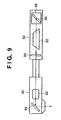
- the exposure light source 80 and illumination optical system 90 can be expressed by a simplified structure shown in Fig. 9.
- the exposure light source 80 and illumination optical system 90 are described with reference to Fig. 9.
- the exposure light source 80 comprises a laser resonator 82, a transmitting mirror 84, a wavelength selecting element 86, and a wavelength selecting element driving mechanism 88.
- the wavelength band can be narrowed.
- the wavelength selecting element driving mechanism 88 can be configured with a step motor, a piezoelectric device or the like.
- the laser beam emitted from the exposure light source 80 transmits through a condensing lens 92 of the illumination optical system 90, thereafter the mirror 94 leads the laser beam to irradiate the reticle.
- a laser driving unit 70 can change the wavelength of a laser beam of the exposure light source 80 by driving the wavelength selecting element driving mechanism 88 shown in Fig. 9.
- a lens driving unit 50 displaces the lens 104 with respect to the optical axis direction by driving a lens driving mechanism 100.
- the lens driving mechanism 100 can be configured with an actuator employing air pressure, or a piezoelectric device or the like. Note, although the first embodiment shows only one system of lens driving mechanism, a plurality of lens driving mechanisms may be included.
- the entire exposure apparatus is controlled by a main control unit 60.
- the wafer stage 130 is driven by the stage driving unit 65 to perform step-and-repeat or step-and-scan driving.
- a barometer 120 measures air pressure in the exposure apparatus.
- the barometer 120 may be arranged in any place of the exposure apparatus, or in the neighborhood of the projection optical system 101, or in the internal portion of the projection optical system 101.
- An output signal of the barometer 120 is inputted to a correction calculation unit 10.
- the correction calculation unit 10 instructs the laser driving unit 70 to change the wavelength of the laser beam, instructs the lens driving unit 50 to drive the lens in the optical axis direction, and instructs the stage driving unit 65 to drive the stage in Z direction, thereby correcting an aberration caused by a change in air pressure.
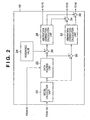
- Fig. 2 shows a construction of the correction calculation unit 10.
- a model calculation unit 20 compensates a response error between the air pressure data measured by the barometer 120 and ambient pressure of the lenses 102, 104, 106, 108 and 110 in the projection optical system 101.
- the ambient pressure of the lenses in the projection optical system has a primary delay characteristic in response to a change in air pressure in the exposure apparatus. For this reason, in a case where the barometer 120 is arranged in the external portion of the projection optical system, an air pressure characteristic of the barometer 120 and ambient pressure characteristics of the lenses are measured in advance and a model is generated.
- the model calculation unit 20 refers to this model to compensate the measured value of the barometer 120, and obtains ambient pressure of the lenses.
- the model calculation unit 20 can be omitted since a response error is small. Note that if the barometer 120 has a large detection noise, smoothing such as filtering or the like may be performed as needed.
- a data holding unit 22 holds a signal from the model calculation unit 20 in accordance with a timing signal from the main control unit 60. It is preferable to use the timing signal immediately after an end of exposure. This operation is described with reference to Figs. 3A to 3E.
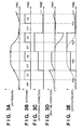
- Figs. 3A to 3E are timing charts showing an operation of the correction calculation unit 10.
- Fig. 3A shows air pressure data detected by the barometer 120.
- Fig. 3B shows ON/OFF of an exposure, i.e., a shot.
- air pressure data after an exposure is completed and off is used.
- it is preferable to use air pressure data immediately after an end of exposure (mark X in Fig 3A).
- Fig. 3E shows how air pressure data is held by the data holding unit 22. In accordance with a timing signal from the main control unit 60 shown in Fig. 2, air pressure data immediately after an end of exposure is held.
- Fig. 3D will be described later in detail.
- the description on the operation of the correction calculation unit 10 continues referring back to Fig. 2.
- the air pressure data immediately after an end of exposure, which has been held by the data holding unit 22, is compared with an air pressure reference value 24 by an adder-subtracter 26 to calculate a difference.
- the difference is inputted to an aberration correction calculation unit 28.
- the aberration correction calculation unit 28 calculates a lens driving amount and a light-source-wavelength changing amount necessary for correcting an aberration based on the air pressure difference data from the adder-subtracter 26, which is updated immediately after an end of exposure.
- an aberration caused by a change in air pressure is extremely large in the projection magnification and focus, thus requiring reduction by correction.
- aberrations such as distortion, spherical aberration, coma, astigmatism, curvature of field and the like are relatively small so that they do not create problems in the exposure characteristics.
- An aberration can be changed by optically designing the lenses of the projection optical system in a way that the direction of the lenses is changed in the optical-axis direction.
- the optical system is designed in a way that one of the lenses is displaced with respect to the optical-axis direction by a lens driving mechanism so as to largely change one aberration.
- the optical system is designed so that the lens 104 is displaced with respect to the optical axis direction by the lens driving mechanism 100 to change the projection magnification.
- other aberrations such as distortion, spherical aberration, coma, astigmatism, curvature of field and the like may slightly change.
- the optical system is generally designed so that n number of aberrations can be corrected by displacing n groups of lenses with respect to the optical-axis direction.
- each aberration changes in accordance with a change in the wavelength of exposure light. Since the sensitivity of aberrations in response to a change in the wavelength differs depending on the lens design, it cannot generally be defined. However, there is an aberration that largely changes in accordance with the wavelength change, and an aberration that changes only slightly.
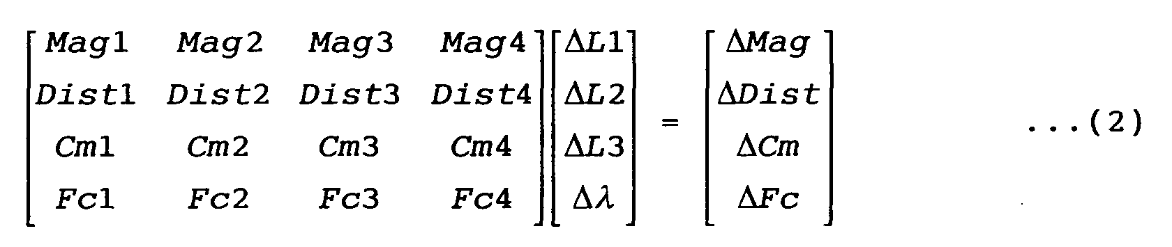
- the aberrations caused by the change in air pressure are predicted to be ⁇ Mag, ⁇ Dist, ⁇ Cm and ⁇ Fc according to the following equation (1).
- the respective driving amounts of the three groups of lenses and the amount of change in the exposure light wavelength necessary for correcting these aberrations are ⁇ L1, ⁇ L2, ⁇ L3, and ⁇
- the aberration sensitivity in response to the respective lens driving and the wavelength change is expressed by matrix A having 4 rows and 4 columns.
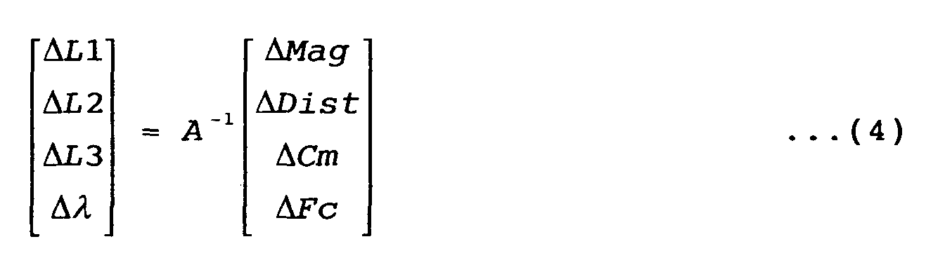
- the respective driving amounts ⁇ L1, ⁇ L2, ⁇ L3 and ⁇ necessary for correcting the aberrations caused by the change in air pressure can be calculated by solving the matrix calculation of equation (4).
- a -1 is an inverse matrix of matrix A having 4 rows and 4 columns.
- the aberration correction calculation unit 28 predicts an aberration caused by the change in air pressure using equation (1), and calculates by equation (4) the lens driving amount and the exposure-light-wavelength changing amount necessary for correcting the aberration.
- the calculated lens driving amount is inputted to an adder 34, and outputted to the lens driving unit 50.
- the lens driving unit 50 displaces the lens with respect to the optical-axis direction using the lens driving mechanism unit.
- the exposure-light-wavelength changing amount calculated by the aberration correction calculation unit 28 is inputted to the laser driving unit 70.
- the laser driving unit 70 changes the wavelength of exposure light using the wavelength selecting element driving mechanism 88 of the exposure light source 80.
- n+1 number of aberrations can be corrected by driving n groups of lenses and changing the wavelength of exposure light.
- focus can be corrected by driving the wafer stage 130 in the optical-axis direction. Correction using the wafer stage 130 is realized in the following manner. First, a focus error caused by a change in air pressure, as well as a focus error caused by the aforementioned lens driving or wavelength change, are calculated separately by the aberration correction calculation unit 28 to obtain the wafer stage driving amount for focus correction.
- the wafer stage driving amount is inputted to the adder 36, and outputted to the stage driving unit 65.
- the stage driving unit 65 displaces the wafer stage 130 with respect to the optical-axis direction, thereby correcting the focus.
- Aberration correction executed by driving the wafer stage in the optical-axis direction in addition to the aforementioned aberration correction executed by driving n groups of lenses and changing the exposure-light wavelength can realize correction of n+2 aberrations.
- the aberration correction calculation unit 28 calculates the lens driving amount and the exposure-light-wavelength changing amount (as well as the wafer stage driving amount in the optical-axis direction) necessary for correcting an aberration caused by a change in air pressure each time an exposure ends. Based on the driving amounts, correction is performed at the timing shown in Fig. 3C. This will be referred to as a shot-interval correction.
- the shot-interval correction is performed between shots based on air pressure data immediately after an end of exposure.
- the aberration correction calculation unit 28 calculates the wavelength changing amount based on the air pressure difference data, which is repeatedly outputted from the adder-subtracter 26 immediately after an end of exposure, using an equation linearly approximated for an optical design purpose which expresses a characteristic of the exposure-light-wavelength changing amount in response to a change in air pressure from a reference air pressure.
- the wavelength changing amount is inputted to the laser driving unit 70, and the wavelength of exposure light is changed using the wavelength selecting element driving mechanism 88 of the exposure light source 80, thereby correcting an aberration caused by a change in air pressure.
- the shot-interval correction is performed only for changing the wavelength of exposure light, and it is not necessary to drive the lens or wafer stage in the optical-axis direction.
- the correction calculation unit 10 performs real-time correction in accordance with a change in air pressure during an exposure (during a shot).
- the output of the data holding unit 22 is inputted to the adder-subtracter 26 as well as the adder-subtracter 30.
- the output from the data holding unit 22 is compared with the air pressure data from the model calculation unit 20, and an air pressure difference value is outputted.
- the air pressure difference value representing a change in air pressure after the shot-interval correction, is inputted moment to moment, i.e., in real time, to an aberration correction calculation unit 32 as shown in Fig. 3D.
- other factors such as the wavelength of the exposure light source are adjusted in the non-exposure state, thereby returning the lens driving position for aberration correction to the neutral position.
- the lens driving amount for aberration correction is reset in the non-exposure state, and an integration value of the lens driving amount is suppressed.
- correction of an aberration caused by a change in air pressure can be realized with a small lens driving range, enabling simplification and downsizing/weight saving of the lens driving mechanism.
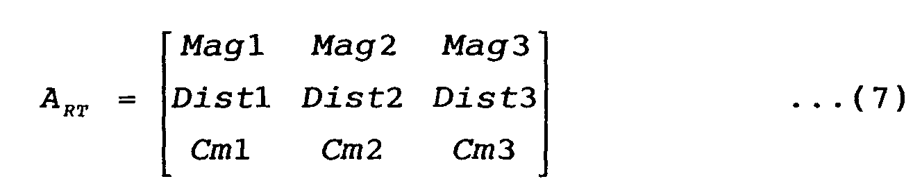
- the aberration correction calculation unit 32 calculates a lens driving amount for correcting m number of aberrations by displacing m groups of lenses with respect to the optical-axis direction. Note that m is the number of group larger than 1, and is smaller than n group which is used in the shot-interval correction.
- a RT -1 is an inverse matrix of matrix A RT having 3 rows and 3 columns.
- the aberration correction calculation unit 32 receives in real time from the adder-subtracter 30 the air-pressure-change data which has been subjected to shot-interval correction, i.e., air pressure difference value. Based on the air pressure difference data outputted in real time (in this embodiment, a change in air pressure from the end of previous shot), the aberration correction calculation unit 32 predicts in real time an aberration caused by the change in air pressure using equation (5), and calculates in real time by equation (8) the lens driving amount necessary for correcting the aberration.
- the calculated lens driving amount is inputted to the adder 34 for adding the lens driving amount on which the above-described shot-interval correction has been performed, and outputted to the lens driving unit 50.
- the lens driving unit 50 displaces the lens in real time with respect to the optical-axis direction using the lens driving mechanism unit, thereby correcting in real time the aberration caused by the change in air pressure.
- the wafer stage 130 may be constructed such that it is displaced with respect to the optical-axis direction to correct the focus.
- a focus error caused by a change in air pressure, as well as a focus error caused by the aforementioned lens driving are calculated separately by the aberration correction calculation unit 32 to obtain the wafer stage driving amount for focus correction in real time.
- the wafer stage driving amount is inputted to the adder 36 for adding a focus correction signal (correction signal for a shot interval) from the aberration correction calculation unit 28, and outputted to the stage driving unit 65.
- the stage driving unit 65 displaces the wafer stage 130 with respect to the optical-axis direction, thereby correcting the focus.
- the aberration correction calculation unit 32 calculates the lens driving amount (as well as the wafer stage driving amount in the optical-axis direction) necessary for correcting an aberration caused by a change in air pressure during an exposure. Based on the driving amount, aberrations caused by a change in air pressure during an exposure can be corrected at the timing shown in Fig. 3D. This will be referred to as a real-time correction.
- aberrations are corrected by shot-interval correction immediately after an end of exposure, and aberrations caused by a change in air pressure between shots are corrected by real-time correction.
- driving the n groups of lenses and driving the light-source wavelength as well as the wafer stage in the optical-axis direction can correct aberrations caused by a change in air pressure.
- n+2 aberrations can be corrected
- n+1 aberrations can be corrected in real time.
- driving the n groups of lenses and driving the light-source wavelength as well as the wafer stage in the optical-axis direction can correct aberrations caused by a change in air pressure.
- all the aberrations can be corrected by changing the exposure-light wavelength
- n+1 aberrations can be corrected in real time by driving the n groups of lenses and driving the wafer stage in the optical-axis direction.
- the aberration correction operation is switched for during a shot interval and for during a shot.
- an aberration correction operation is switched for performing the correction at long time intervals and for performing the correction at short time intervals.
- aberration correction at short time intervals corrects an aberration by driving the lens in the optical-axis direction
- aberration correction at long time intervals corrects an aberration by changing the exposure-light wavelength, or by driving the lens in the optical-axis direction and changing the exposure-light wavelength.
- the aberration correction at short time intervals is repeatedly executed during an exposure and in the non-exposure state of the wafer exposure processing, and the aberration correction at long time intervals is executed when wafer exchange processing is performed.
- the construction of the correction calculation unit 10 according to the second embodiment is identical to that of the first embodiment (Fig. 2). However in the second embodiment, the timing signal outputted from the main control unit 60 is different.
- the timing signal from the main control unit 60 to the data holding unit 22 in Fig. 2 is outputted after all the exposure processing for one wafer is completed.
- the signal from the model calculation unit 20 is held by the data holding unit 22.
- several timing signals may be outputted to update air pressure data in the data holding unit 22.
- the aberration correction executed according to this timing signal is called the aberration correction at long time intervals. Therefore, the aberration correction at long time intervals is similar to the shot-interval correction described in the first embodiment.
- the main control unit 60 When the wafer exchange is completed and exposure processing begins for a newly loaded wafer, the main control unit 60 does not output a timing signal until all the exposure processing for this wafer is completed. Therefore, while the data holding unit 22 maintains the air pressure data, correction is repeatedly performed on an aberration caused by a change in air pressure during an exposure of one wafer and in the non-exposure state, similarly to the real-time correction described in the first embodiment. This aberration correction is called the aberration correction at short time intervals.
- driving the n groups of lenses and driving the light-source wavelength as well as the wafer stage in the optical-axis direction can correct aberrations caused by a change in air pressure.
- n+2 aberrations can be corrected, and during a shot as well as during a shot interval, n+1 aberrations can be corrected in real time.
- driving the n groups of lenses and driving the light-source wavelength as well as the wafer stage in the optical-axis direction can correct aberrations caused by a change in air pressure.
- all the aberrations can be corrected by changing the exposure-light wavelength, and during a shot as well as during a shot interval, n+1 aberrations can be corrected in real time.
- the third embodiment of the present invention is described.
- higher speed and higher precision of the barometer which detects a change in air pressure is achieved.
- Fig. 4 shows a configuration of an exposure apparatus according to the third embodiment of the present invention.
- the same reference numerals are assigned and description thereof is omitted.
- the components different from the first embodiment are described.
- a new barometer 122 is added to the construction shown in Fig. 1, and a correction calculation unit 10a is provided.
- the barometers 120 and 122 will be referred to as the first barometer and second barometer respectively.
- the first barometer 120 measures an absolute value of air pressure with high precision (a barometer having a calibration function performing calibration according to the environment).
- the second barometer 122 measures an absolute value or a relative value of air pressure at higher speed than the first barometer.
- the first barometer for measuring an absolute value of air pressure can measure air pressure with high precision without receiving an influence of the temperature or humidity, because it outputs an air pressure measurement value after removing an influence of the temperature or humidity, the response speed as a sensor is low.
- the second barometer for measuring an absolute value or a relative value of air pressure performs air pressure measurement by a wavelength tracker which is configured with, e.g., a laser interferometer, the response speed is extremely high.
- the wavelength tracker is a measuring equipment that measures a medium, i.e., a refractive index of air, by making use of a laser beam, and outputs a refractive index of air pressure, temperature and humidity at high speed.
- the refractive index n of the output of the wavelength tracker varies according to the air pressure P.
- the air pressure P can be calculated from equation (9). Therefore, the wavelength tracker can serve as a barometer.
- the wavelength tracker has sensitivity to a temperature and relative humidity, when the wavelength tracker is used as a barometer, it is necessary that the environmental conditions be constant.
- the wavelength tracker has a barometric error of 0.034 hPa as a barometer when the temperature fluctuates by 0.01 C°, and has a barometric error of 0.045 hPa as a barometer when the humidity fluctuates by 1%. Therefore, to reduce the barometric error and achieve highly precise correction of an aberration caused by a change in air pressure, it is necessary to suppress the temperature fluctuation to at least 0.01 C° or less and suppress the humidity fluctuation to at least 1% or less.
- the temperature in the interior of the exposure apparatus is controlled with the precision of approximately 0.01 C° or less for maintaining the precision of the apparatus. Since the temperature fluctuation is sufficiently small, the measurement error of the wavelength tracker caused by the temperature fluctuation can be disregarded. However, it is often the case that the humidity is not actively controlled, thus a slight and gradual fluctuation in humidity may occur. In such case, as is apparent from equations (9) and (10), the humidity fluctuation causes a change in the refractive index outputted from the wavelength tracker, generating a barometric error.
- the third embodiment comprises as the first barometer 120 a barometer which has low response speed but detects an absolute value of air pressure without receiving an influence of the temperature or humidity, and comprises as the second barometer 122 a barometer which detects an absolute value or a relative value of air pressure at high speed and which easily receives an influence of the temperature or humidity.
- Fig. 5 shows a construction of the correction calculation unit 10a according to the third embodiment.
- the same reference numerals are assigned and description thereof is omitted.
- a calibration calculation unit 18 is newly added to the correction calculation unit 10a.
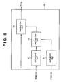
- An operation of the calibration calculation unit 18 is described with reference to Fig. 6.
- An output of the first barometer 120 is inputted to an averaging unit 14 while an output of the second barometer 122 is inputted to an averaging unit 12.
- Respective air pressure data is averaged by the averaging units 12 and 14, and the averaged data is inputted to a calculation unit 15.
- the calculation unit 15 calculates an offset of the output data of the averaging unit 12 outputted from the second barometer 122, based on the output data of the averaging unit 14 outputted from the first barometer 120. More specifically, the calculation unit 15 calculates a difference between the data from the averaging unit 14 and the data from the averaging unit 12. The offset calculated by the calculation unit 15 is inputted to a calibration unit 16.
- the calibration unit 16 performs calibration on the air pressure data transmitted moment to moment, i.e., in real time, from the second barometer 122 based on the offset signal outputted by the calculation unit 15, and outputs the calibrated data as accurate air pressure data to the model calculation unit 20.
- the averaging time of the averaging units 12 and 14 may range from tens of seconds to several minutes or from tens of minutes to several hours. For instance, if there is a possibility that the humidity fluctuates within several minutes to tens of minutes, respective air pressure data is averaged while exposure processing is performed for one wafer and an offset is calculated by the calculation unit 15 while the wafer is exchanged to update the value. Then, in the wafer exposure processing, the updated offset is used to calibrate the data from the second barometer 122. In this manner, each time one wafer is processed, an offset value serving as calibration data can be calculated and updated by the calculation unit 15 for calibration of the data outputted by the second barometer 122.
- averaging processing is performed for approximately several minutes by the averaging units 12 and 14 when a reticle is exchanged or when the exposure apparatus is started. Then, an offset is calculated by the calculation unit 15 to update and maintain the value, and the calibration unit 16 performs calibration on the data from the second barometer 122.
- the calibration calculation unit 18 employs the data outputted by the first barometer 120, which has low response speed but can measure an absolute value of air pressure with high precision, to perform calibration on the data outputted by the second barometer 122, which has high response speed but causes a barometric error due to humidity fluctuation or the like. As a result, air pressure data can be obtained with high precision at high response speed.
- the constructions of the model calculation unit 20 and other components shown in Fig. 5 are similar to that of the first embodiment and second embodiment.
- an aberration caused by a change in air pressure can be corrected with high precision during a shot interval or in real time as described in the first embodiment.
- aberration correction can be executed at short time intervals and long time intervals as described in the second embodiment.
- n+2 aberrations caused by a change in air pressure can be corrected during a shot interval by driving the n groups of lenses and driving the light-source wavelength as well as the wafer stage in the optical-axis direction, and n+1 aberrations can be corrected in real time during a shot by driving the n groups of lenses and driving the wafer stage in the optical-axis direction.
- all aberrations caused by a change in air pressure can be corrected during a shot interval by driving the exposure-light wavelength, and n+1 aberrations can be corrected in real time during a shot by driving the n groups of lenses and driving the wafer stage in the optical-axis direction.
- a slight or sudden change in air pressure during an exposure or in the non-exposure state can be detected at high speed with high precision, because the output from the first barometer 120 which has low response speed but can detect an absolute value of air pressure with high precision is employed to perform calibration on the absolute value or relative value of air pressure outputted by the second barometer 122 which has high response speed but is sensitive to an environmental change other than air pressure such as humidity. Accordingly, either the case where lenses of the projection optical system are configured with a single glass material or the case where the lenses are not configured with a single glass material, it is possible to correct in real time an aberration caused by a slight or sudden change in air pressure during an exposure or in the non-exposure state.
- the apparatus is constructed such that an aberration is corrected by driving the lens and driving the wafer stage in the optical-axis direction at short time intervals, and that an aberration is corrected by changing the exposure-light wavelength or by driving the lens and changing the exposure-light wavelength at long time intervals.
- the short time interval may be of an interval of the correction executed during an exposure or in the non-exposure state of wafer exposure processing.
- the long time interval may be of an interval of the correction executed in the non-exposure state when wafer exchange processing is performed.
- the fourth embodiment describes an aberration correction performed in a case where the lenses of the projection optical system are configured with a single glass material or the lenses have a characteristic that can be regarded as a single glass material. Therefore, in the fourth embodiment, all aberrations are always corrected in real time by changing the wavelength of a laser beam.
- Fig. 7 shows a construction of a correction calculation unit 10b according to the fourth embodiment.
- the data holding unit 22, adder-subtracter 30, and aberration correction calculation unit 32 are excluded from the correction calculation unit 10 of the third embodiment (Fig. 5).
- the aberration correction calculation unit 28b which is similar to the aberration correction calculation unit 28, only outputs a wavelength changing signal to the laser driving unit 70.
- the lenses of the projection optical system 101 according to the fourth embodiment are configured with a single glass material or have a characteristic that can be regarded as a single glass material. Because the lenses can be regarded as a single glass material, it is possible to correct all aberrations caused by a change in air pressure by changing the wavelength of exposure light.
- the data from the second barometer 122 transmitted in real time is calibrated by the calibration calculation unit 18 based on the data from the first barometer 120, and the calibrated data is subjected to predetermined modeling calculation in the model calculation unit 20 as necessary.
- the output value is compared with the air pressure reference value 24, and a difference is calculated by the adder-subtracter 26.
- the aberration correction calculation unit 28b calculates a wavelength changing amount using an exposure-light-wavelength changing amount characteristic equation calculating a change in the air pressure measurement value (output of the model calculation unit 20) from the reference air pressure (reference value 24).
- the calculated wavelength changing amount is inputted to the laser driving unit 70.
- the laser driving unit 70 changes the wavelength of the exposure light source 80 using the wavelength selecting element driving mechanism 88. In this manner, an aberration caused by air pressure is corrected. In this case, real time correction is performed only for changing the wavelength of exposure light, and it is not necessary to drive the lens or wafer stage in the optical-axis direction.
- an aberration caused by a change in air pressure is corrected during a shot interval as well as in real time by changing a wavelength of exposure light.
- an output from the first barometer 120 which has low response speed but can detect an absolute value of air pressure with high precision
- calibration is performed on an output from the second barometer 122 (an absolute value or a relative value of air pressure) which has high response speed but is sensitive to an environmental change other than air pressure such as humidity.
- the fifth embodiment describes a case where the lenses of the projection optical system are not configured with a single glass material.
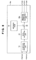
- Fig. 8 shows a construction of a correction calculation unit 10c according to the fifth embodiment.
- the correction calculation unit according to the fifth embodiment has an aberration correction calculation unit 28c in place of the aberration correction calculation unit 28b in the correction calculation unit 10b of the fourth embodiment (Fig. 7).
- the aberration correction calculation unit 28c which is similar to the aberration correction calculation unit 28, outputs a lens driving signal to the lens driving unit, outputs a wafer stage driving signal in the optical-axis direction to the stage driving unit 65, and outputs a wavelength changing signal to the laser driving unit 70 for correcting an aberration caused by a change in air pressure.
- the lenses of the projection optical system according to the fifth embodiment are not configured with a single glass material. Therefore, based on air pressure difference data transmitted in real time from the adder-subtracter 26, the aberration correction calculation unit 28c predicts an aberration caused by a change in air pressure using equation (1), and calculates by equation (4) a lens driving amount and an exposure-light-wavelength changing amount necessary for correcting the aberration.
- the calculated lens driving amount is outputted to the lens driving unit 50, and the lens is displaced with respect to the optical-axis direction using the lens driving mechanism unit, thereby correcting the aberration caused by the change in air pressure.
- the calculated exposure-light-wavelength changing amount is inputted to the laser driving unit 70, and the wavelength is changed by the wavelength selecting element driving mechanism 88 of the exposure light source 80, thereby correcting the aberration caused by the change in air pressure.
- focus can be corrected by driving the wafer stage 130 in the optical-axis direction. Correction using the wafer stage 130 is realized in the following manner. First, a focus error caused by a change in air pressure, as well as a focus error caused by the aforementioned lens driving or wavelength change, are calculated separately by the aberration correction calculation unit 28c to obtain the wafer stage driving amount for focus correction. The wafer stage driving amount is outputted to the stage driving unit 65. The stage driving unit 65 displaces the wafer stage 130 with respect to the optical-axis direction, thereby correcting the focus. Aberration correction executed by driving the wafer stage in the optical-axis direction in addition to the aforementioned aberration correction (n+1 aberration corrections) executed by driving n groups of lenses and changing the exposure-light wavelength can realize correction of n+2 aberrations.
- the aberration correction calculation unit 28c calculates, regardless of whether it is during an exposure or in the non-exposure state, a lens driving amount and an exposure-light-wavelength changing amount (as well as the wafer stage driving amount in the optical-axis direction) necessary for correcting an aberration constantly caused by a change in air pressure.
- a lens driving amount and an exposure-light-wavelength changing amount (as well as the wafer stage driving amount in the optical-axis direction) necessary for correcting an aberration constantly caused by a change in air pressure.
- an output from the first barometer 120 which has low response speed but can detect an absolute value of air pressure with high precision
- calibration is performed on an output from the second barometer 122 (an absolute value or a relative value of air pressure) which has high response speed but is sensitive to an environmental change other than air pressure such as humidity.
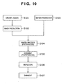
- Fig. 10 shows a production flow of micro devices (semiconductor chips such as an IC or LSI, liquid crystal panels, CCD, thin-film magnetic heads, micro machines, and so forth).
- step S101 circuit design
- step S102 mask production
- step S103 wafer production
- step S104 wafer process
- step S105 semiconductor chip is manufactured using the wafer produced in step S104.
- step S105 includes an assembling process (dicing, bonding), a packaging process (chip embedding) and so on.
- step S106 the semiconductor device manufactured in step S105 is subjected to inspection such as an operation-check test, durability test and so on.
- the semiconductor device manufactured in the foregoing processes is shipped (step S107).
- Fig. 11 shows a flow of the aforementioned wafer process in detail.
- step S111 oxidization
- step S112 CVD
- step S113 electrode forming
- step S114 ion implantation
- step S115 resist process
- step S116 exposure
- step S116 exposure
- step S117 development
- step S118 etching
- steps other than the developed resist image are removed.
- step S119 resist separation
Landscapes
- Physics & Mathematics (AREA)
- General Physics & Mathematics (AREA)
- Health & Medical Sciences (AREA)
- Engineering & Computer Science (AREA)
- Environmental & Geological Engineering (AREA)
- Epidemiology (AREA)
- Public Health (AREA)
- Life Sciences & Earth Sciences (AREA)
- Atmospheric Sciences (AREA)
- Toxicology (AREA)
- Exposure And Positioning Against Photoresist Photosensitive Materials (AREA)
- Exposure Of Semiconductors, Excluding Electron Or Ion Beam Exposure (AREA)
Abstract
Description





Claims (14)
- An exposure apparatus comprising:air pressure measurement means for measuring air pressure in a neighborhood of or inside a projection optical system;first correction means, including aberration adjustment by driving a lens of the projection optical system, for repeatedly executing correction of an aberration based on the air pressure which is measured by said air pressure measurement means; andsecond correction means, including aberration adjustment by changing a wavelength of an exposure light source, for executing correction of an aberration at a time interval longer than a repetition of the aberration correction executed by said first correction means, based on the air pressure which is measured by said air pressure measurement means.
- The exposure apparatus according to claim 1,
wherein said second correction means corrects more aberrations than that of the first correction means. - The exposure apparatus according to claim 1,
wherein said first correction means performs correction at least during a shot of an exposure, and said second correction means performs correction in a non-shot state of the exposure. - The exposure apparatus according to claim 1,
wherein said first correction means performs correction from the beginning of an exposure process for a wafer to the end of all shots of the exposure, and said second correction means performs correction while the wafer is exchanged after the end of said exposure process. - The exposure apparatus according to any one of claims 1 to 4, wherein said second correction means performs aberration correction by changing the wavelength, or by changing the wavelength and driving the lens.
- The exposure apparatus according to any one of claims 1 to 4, further comprising stage driving means for adjusting an aberration by driving a wafer stage in the optical-axis direction,
wherein said first correction means and said second correction means performs aberration correction using said stage driving means. - The exposure apparatus according to claim 1,
wherein said air pressure measurement means comprises:a first barometer for detecting an absolute value of air pressure;a second barometer for detecting an absolute value or a relative value of air pressure at higher speed than said first barometer; andcalibration means for calibrating an output of said second barometer based on an output of said first barometer, and outputting a calibration result as the measured air pressure value. - An exposure apparatus comprising:a first barometer for detecting an absolute value of air pressure;a second barometer for detecting an absolute value or a relative value of air pressure at higher speed than said first barometer;calibration means for calibrating an output of said second barometer based on an output of said first barometer, and outputting a calibration result as a measured air pressure value; andaberration correction means for performing aberration correction based on the air pressure value outputted by said calibration means.
- The exposure apparatus according to claim 8,
wherein said aberration correction means performs aberration correction by employing at least one of:aberration correction utilizing wavelength changing means which adjusts an aberration by changing a wavelength of an exposure light source, aberration correction utilizing lens driving means which adjusts an aberration by driving a lens of a projection optical system, and aberration correction utilizing stage driving means which adjusts an aberration by driving a wafer stage in an optical-axis direction. - The exposure apparatus according to any one of claims 7 to 9, wherein said second barometer is configured with a laser interferometer.
- An aberration correction method for correcting an aberration based on an air pressure value measured by air pressure measurement means that measures air pressure in a neighborhood of or inside a projection optical system, said method comprising:a first correction step of repeatedly executing correction of a predetermined number of aberrations based on the air pressure value which is measured by the air pressure measurement means, said step including aberration adjustment by driving a lens of the projection optical system; anda second correction step of executing aberration correction at a time interval longer than a repetition of the aberration correction executed in said first correction step, based on the air pressure which is measured by the air pressure measurement means, said step including aberration adjustment by changing a wavelength of an exposure light source.
- A method of correcting an aberration caused by a change in air pressure in an exposure apparatus, comprising:a calibration step of calibrating an output of a second barometer based on an output of a first barometer and outputting a calibration result as a measured air pressure value, said first barometer detecting an absolute value of air pressure and said second barometer detecting an absolute value or a relative value of air pressure at higher speed than the first barometer; andan aberration correction step of performing aberration correction based on the air pressure value outputted in said calibration step.
- Apparatus for exposing a substrate with a pattern on a master, comprising:illumination means for illuminating the master with light;projection means, comprising one or more optical elements, for projecting an image of a pattern onto a substrate;air pressure measuring means; andadjustment means for (a) intermittently adjusting the wavelength of the light from the illumination means in response to measurement of air pressure by the air pressure measuring means, and (b) adjusting continuously, or more frequently than the said adjusting of the wavelength of light, at least one optical element of the projection means in response to the measurement of air pressure by the air pressure measuring means.
- Apparatus for exposing a substrate with a pattern on a master, comprising:first air pressure measuring means;second air pressure measuring means, which is responsive to changes in air pressure more quickly than the first air pressure measuring means;means for calibrating an output of the second air pressure measuring means in accordance with an output of the first air pressure measuring means; andmeans for adjusting a parameter of the apparatus in accordance with the calibrated output of the second air pressure measuring means.
Applications Claiming Priority (2)
| Application Number | Priority Date | Filing Date | Title |
|---|---|---|---|
| JP2003070594A JP2004281697A (en) | 2003-03-14 | 2003-03-14 | Exposure apparatus and aberration correction method |
| JP2003070594 | 2003-03-14 |
Publications (2)
| Publication Number | Publication Date |
|---|---|
| EP1469350A2 true EP1469350A2 (en) | 2004-10-20 |
| EP1469350A3 EP1469350A3 (en) | 2009-04-15 |
Family
ID=32905944
Family Applications (1)
| Application Number | Title | Priority Date | Filing Date |
|---|---|---|---|
| EP04251369A Withdrawn EP1469350A3 (en) | 2003-03-14 | 2004-03-10 | Exposure apparatus and aberration correction method |
Country Status (5)
| Country | Link |
|---|---|
| US (3) | US6995828B2 (en) |
| EP (1) | EP1469350A3 (en) |
| JP (1) | JP2004281697A (en) |
| KR (2) | KR100646273B1 (en) |
| CN (2) | CN1322374C (en) |
Cited By (1)
| Publication number | Priority date | Publication date | Assignee | Title |
|---|---|---|---|---|
| EP1835349A1 (en) * | 2006-03-13 | 2007-09-19 | ASML Netherlands BV | Lithographic apparatus, control system and device manufacturing method |
Families Citing this family (25)
| Publication number | Priority date | Publication date | Assignee | Title |
|---|---|---|---|---|
| JP3833209B2 (en) * | 2003-10-24 | 2006-10-11 | キヤノン株式会社 | Exposure apparatus and device manufacturing method |
| US20050192895A1 (en) * | 2004-02-10 | 2005-09-01 | First Data Corporation | Methods and systems for processing transactions |
| JP4752473B2 (en) * | 2004-12-09 | 2011-08-17 | 株式会社ニコン | Exposure apparatus, exposure method, and device manufacturing method |
| TWI406101B (en) * | 2005-03-01 | 2013-08-21 | Univ Meijo | 2-beam interference exposure apparatus, 2-beam interference exposure method, method of manufacturing semiconductor light-emitting element, and semiconductor light-emitting element |
| US7525638B2 (en) * | 2005-03-23 | 2009-04-28 | Asml Netherlands B.V. | Lithographic apparatus and device manufacturing method |
| WO2006133800A1 (en) | 2005-06-14 | 2006-12-21 | Carl Zeiss Smt Ag | Lithography projection objective, and a method for correcting image defects of the same |
| WO2007096949A1 (en) * | 2006-02-21 | 2007-08-30 | Fujitsu Limited | Photo lithography system, photo lithography method and method for fabricating electronic device |
| US8027023B2 (en) | 2006-05-19 | 2011-09-27 | Carl Zeiss Smt Gmbh | Optical imaging device and method for reducing dynamic fluctuations in pressure difference |
| DE102006023876A1 (en) * | 2006-05-19 | 2007-11-22 | Carl Zeiss Smt Ag | Optical imaging device |
| DE102006032877A1 (en) * | 2006-07-15 | 2008-01-17 | Carl Zeiss Smt Ag | Microlithographic projection exposure machine |
| US7372633B2 (en) * | 2006-07-18 | 2008-05-13 | Asml Netherlands B.V. | Lithographic apparatus, aberration correction device and device manufacturing method |
| JP4366386B2 (en) | 2006-09-07 | 2009-11-18 | キヤノン株式会社 | Exposure apparatus and device manufacturing method |
| US20080159644A1 (en) * | 2006-12-28 | 2008-07-03 | Kelly Sean C | Condition dependent sharpening in an imaging device |
| JP2009004509A (en) | 2007-06-20 | 2009-01-08 | Canon Inc | Exposure apparatus and device manufacturing method |
| DE102007036813B4 (en) | 2007-08-03 | 2010-12-30 | Vistec Semiconductor Systems Gmbh | Method for determining positions of structures on a substrate |
| JP2009094163A (en) * | 2007-10-04 | 2009-04-30 | Canon Inc | Temperature control apparatus, exposure apparatus, and device manufacturing method |
| DE102008042356A1 (en) | 2008-09-25 | 2010-04-08 | Carl Zeiss Smt Ag | Projection exposure system with optimized adjustment option |
| CN102540745B (en) * | 2010-12-22 | 2014-01-22 | 上海微电子装备有限公司 | Exposure system based on control of principal component of space image |
| JP6025419B2 (en) * | 2012-06-27 | 2016-11-16 | 株式会社ニューフレアテクノロジー | Inspection method and inspection apparatus |
| DE102012212758A1 (en) * | 2012-07-20 | 2014-01-23 | Carl Zeiss Smt Gmbh | System correction from long time scales |
| NL2017691A (en) * | 2015-11-20 | 2017-06-02 | Asml Netherlands Bv | Lithographic Apparatus and Method |
| JP7213761B2 (en) * | 2019-06-18 | 2023-01-27 | キヤノン株式会社 | EXPOSURE APPARATUS AND ARTICLE MANUFACTURING METHOD |
| US11581692B2 (en) | 2019-06-18 | 2023-02-14 | KLA Corp. | Controlling pressure in a cavity of a light source |
| JP6924235B2 (en) * | 2019-09-19 | 2021-08-25 | キヤノン株式会社 | Exposure method, exposure equipment, article manufacturing method, and semiconductor device manufacturing method |
| DE102022200539A1 (en) | 2022-01-18 | 2022-11-17 | Carl Zeiss Smt Gmbh | Optical system for projection lithography |
Family Cites Families (25)
| Publication number | Priority date | Publication date | Assignee | Title |
|---|---|---|---|---|
| US4666273A (en) * | 1983-10-05 | 1987-05-19 | Nippon Kogaku K. K. | Automatic magnification correcting system in a projection optical apparatus |
| JP2516194B2 (en) * | 1984-06-11 | 1996-07-10 | 株式会社日立製作所 | Projection exposure method |
| JPS618922A (en) * | 1984-06-25 | 1986-01-16 | Nippon Kogaku Kk <Nikon> | Projecting optical apparatus |
| US5095190A (en) * | 1987-03-03 | 1992-03-10 | Canon Kabushiki Kaisha | Exposure apparatus |
| DE3733823A1 (en) * | 1987-10-07 | 1989-04-20 | Zeiss Carl Fa | METHOD FOR COMPENSATING THE INFLUENCE OF ENVIRONMENTAL PARAMETERS ON THE IMAGE PROPERTIES OF AN OPTICAL SYSTEM |
| KR920005348Y1 (en) * | 1988-03-01 | 1992-08-03 | 미쓰비시전기주식회사 | Pressure sensor |
| JP2864060B2 (en) * | 1991-09-04 | 1999-03-03 | キヤノン株式会社 | Reduction projection type exposure apparatus and method |
| JPH0645228A (en) | 1992-07-23 | 1994-02-18 | Nikon Corp | Projection aligner |
| JP3500619B2 (en) * | 1993-10-28 | 2004-02-23 | 株式会社ニコン | Projection exposure equipment |
| JP3379200B2 (en) * | 1994-03-25 | 2003-02-17 | 株式会社ニコン | Position detection device |
| JP3402850B2 (en) | 1995-05-09 | 2003-05-06 | キヤノン株式会社 | Projection exposure apparatus and device manufacturing method using the same |
| USH1937H1 (en) * | 1996-02-29 | 2001-02-06 | The United States Of America As Represented By The United States Department Of Energy | Laser barometer |
| JPH10270333A (en) * | 1997-03-27 | 1998-10-09 | Nikon Corp | Exposure equipment |
| WO1999010917A1 (en) * | 1997-08-26 | 1999-03-04 | Nikon Corporation | Aligner, exposure method, method of pressure adjustment of projection optical system, and method of assembling aligner |
| JP3278407B2 (en) * | 1998-02-12 | 2002-04-30 | キヤノン株式会社 | Projection exposure apparatus and device manufacturing method |
| EP1126510A4 (en) * | 1998-09-17 | 2003-03-26 | Nikon Corp | METHOD FOR ADJUSTING AN OPTICAL PROJECTION SYSTEM |
| JP3670900B2 (en) | 1999-08-30 | 2005-07-13 | 三菱重工業株式会社 | Transmitter automatic calibration method and transmitter automatic calibration apparatus |
| JP3387861B2 (en) * | 1999-09-09 | 2003-03-17 | キヤノン株式会社 | Exposure apparatus and device manufacturing method |
| JP4532647B2 (en) * | 2000-02-23 | 2010-08-25 | キヤノン株式会社 | Exposure equipment |
| JP2001274054A (en) * | 2000-03-24 | 2001-10-05 | Canon Inc | Exposure apparatus, semiconductor device manufacturing method, and semiconductor device manufacturing factory |
| JP4666747B2 (en) * | 2000-11-06 | 2011-04-06 | キヤノン株式会社 | Exposure apparatus and device manufacturing method |
| JP3619141B2 (en) * | 2000-11-10 | 2005-02-09 | キヤノン株式会社 | Projection exposure apparatus and device manufacturing method |
| JP2002222760A (en) | 2001-01-29 | 2002-08-09 | Canon Inc | Exposure method, exposure apparatus, and device manufacturing method |
| JP4120855B2 (en) | 2001-04-10 | 2008-07-16 | 横河電機株式会社 | Pressure sensor |
| JP2003068622A (en) * | 2001-08-28 | 2003-03-07 | Canon Inc | Exposure apparatus, control method therefor, and device manufacturing method |
-
2003
- 2003-03-14 JP JP2003070594A patent/JP2004281697A/en active Pending
-
2004
- 2004-03-04 US US10/791,821 patent/US6995828B2/en not_active Expired - Fee Related
- 2004-03-10 EP EP04251369A patent/EP1469350A3/en not_active Withdrawn
- 2004-03-10 KR KR1020040016052A patent/KR100646273B1/en not_active Expired - Fee Related
- 2004-03-12 CN CNB2004100284781A patent/CN1322374C/en not_active Expired - Fee Related
- 2004-03-12 CN CNA2005100884982A patent/CN1722000A/en active Pending
-
2005
- 2005-08-11 US US11/201,426 patent/US7164464B2/en not_active Expired - Fee Related
-
2006
- 2006-03-13 KR KR1020060023110A patent/KR100603006B1/en not_active Expired - Fee Related
- 2006-10-06 US US11/539,316 patent/US7760326B2/en not_active Expired - Fee Related
Cited By (1)
| Publication number | Priority date | Publication date | Assignee | Title |
|---|---|---|---|---|
| EP1835349A1 (en) * | 2006-03-13 | 2007-09-19 | ASML Netherlands BV | Lithographic apparatus, control system and device manufacturing method |
Also Published As
| Publication number | Publication date |
|---|---|
| US7760326B2 (en) | 2010-07-20 |
| US6995828B2 (en) | 2006-02-07 |
| EP1469350A3 (en) | 2009-04-15 |
| CN1322374C (en) | 2007-06-20 |
| KR100603006B1 (en) | 2006-07-24 |
| KR20040081331A (en) | 2004-09-21 |
| CN1530753A (en) | 2004-09-22 |
| JP2004281697A (en) | 2004-10-07 |
| CN1722000A (en) | 2006-01-18 |
| KR20060030081A (en) | 2006-04-07 |
| US20060017898A1 (en) | 2006-01-26 |
| US20040179175A1 (en) | 2004-09-16 |
| KR100646273B1 (en) | 2006-11-17 |
| US20070085986A1 (en) | 2007-04-19 |
| US7164464B2 (en) | 2007-01-16 |
Similar Documents
| Publication | Publication Date | Title |
|---|---|---|
| US7164464B2 (en) | Exposure apparatus and aberration correction method | |
| US7088426B2 (en) | Projection optical system adjustment method, prediction method, evaluation method, adjustment method, exposure method and exposure apparatus, program, and device manufacturing method | |
| US7965387B2 (en) | Image plane measurement method, exposure method, device manufacturing method, and exposure apparatus | |
| JP3402850B2 (en) | Projection exposure apparatus and device manufacturing method using the same | |
| US7941232B2 (en) | Control method, control system, and program | |
| JP3445045B2 (en) | Projection exposure apparatus and device manufacturing method using the same | |
| KR20070113114A (en) | Optical element drive | |
| KR101124776B1 (en) | Exposure apparatus and method of manufacturing device | |
| US7804581B2 (en) | Exposure apparatus and method of manufacturing device | |
| KR100327841B1 (en) | Projection exposure appratus and device manufacturing method | |
| US8253924B2 (en) | Exposure method, exposure apparatus and device manufacturing method | |
| US20100124724A1 (en) | Projection exposure apparatus, method for calibrating measurement criterion of displacement measurement unit, and method for manufacturing device | |
| US6614503B1 (en) | Projection exposure apparatus, and device manufacturing method which compensate for a change in optical performance of a projection optical system | |
| WO1999026279A1 (en) | Exposure method and aligner | |
| US7486379B2 (en) | Exposure apparatus, method applied to the apparatus, and device manufacturing method | |
| JPH0963923A (en) | X-ray projection exposure apparatus | |
| HK1114691A (en) | Exposure method, exposure apparatus and device manufacturing method | |
| HK1118953A (en) | Exposure method, exposure device, and device manufacturing method |
Legal Events
| Date | Code | Title | Description |
|---|---|---|---|
| PUAI | Public reference made under article 153(3) epc to a published international application that has entered the european phase |
Free format text: ORIGINAL CODE: 0009012 |
|
| AK | Designated contracting states |
Kind code of ref document: A2 Designated state(s): AT BE BG CH CY CZ DE DK EE ES FI FR GB GR HU IE IT LI LU MC NL PL PT RO SE SI SK TR |
|
| AX | Request for extension of the european patent |
Extension state: AL HR LT LV MK |
|
| PUAL | Search report despatched |
Free format text: ORIGINAL CODE: 0009013 |
|
| AK | Designated contracting states |
Kind code of ref document: A3 Designated state(s): AT BE BG CH CY CZ DE DK EE ES FI FR GB GR HU IE IT LI LU MC NL PL PT RO SE SI SK TR |
|
| AX | Request for extension of the european patent |
Extension state: AL LT LV MK |
|
| 17P | Request for examination filed |
Effective date: 20091015 |
|
| AKX | Designation fees paid |
Designated state(s): DE FR GB IT NL |
|
| 17Q | First examination report despatched |
Effective date: 20130311 |
|
| STAA | Information on the status of an ep patent application or granted ep patent |
Free format text: STATUS: THE APPLICATION HAS BEEN WITHDRAWN |
|
| 18W | Application withdrawn |
Effective date: 20130711 |