EP1469332A1 - Device for connecting optical fibres to light emitter and receiver circuits - Google Patents
Device for connecting optical fibres to light emitter and receiver circuits Download PDFInfo
- Publication number
- EP1469332A1 EP1469332A1 EP03731724A EP03731724A EP1469332A1 EP 1469332 A1 EP1469332 A1 EP 1469332A1 EP 03731724 A EP03731724 A EP 03731724A EP 03731724 A EP03731724 A EP 03731724A EP 1469332 A1 EP1469332 A1 EP 1469332A1
- Authority
- EP
- European Patent Office
- Prior art keywords
- optical fiber
- systems
- section
- optical fibre
- conductor
- Prior art date
- Legal status (The legal status is an assumption and is not a legal conclusion. Google has not performed a legal analysis and makes no representation as to the accuracy of the status listed.)
- Withdrawn
Links
- 230000003287 optical effect Effects 0.000 title description 3
- 239000013307 optical fiber Substances 0.000 claims abstract description 55
- 239000004020 conductor Substances 0.000 claims abstract description 45
- 239000002775 capsule Substances 0.000 claims abstract description 20
- 239000011248 coating agent Substances 0.000 claims abstract description 12
- 238000000576 coating method Methods 0.000 claims abstract description 12
- 230000004048 modification Effects 0.000 description 3
- 238000012986 modification Methods 0.000 description 3
- 239000000835 fiber Substances 0.000 description 2
- 238000004519 manufacturing process Methods 0.000 description 2
- 230000007246 mechanism Effects 0.000 description 2
- 230000000750 progressive effect Effects 0.000 description 2
- 230000009467 reduction Effects 0.000 description 2
- 229910052709 silver Inorganic materials 0.000 description 2
- 239000004332 silver Substances 0.000 description 2
- 230000009471 action Effects 0.000 description 1
- 230000002411 adverse Effects 0.000 description 1
- 230000005540 biological transmission Effects 0.000 description 1
- 239000003795 chemical substances by application Substances 0.000 description 1
- 230000007423 decrease Effects 0.000 description 1
- -1 dirt Substances 0.000 description 1
- 230000005489 elastic deformation Effects 0.000 description 1
- 230000001788 irregular Effects 0.000 description 1
- 239000000843 powder Substances 0.000 description 1
- 239000011347 resin Substances 0.000 description 1
- 229920005989 resin Polymers 0.000 description 1
- 238000007789 sealing Methods 0.000 description 1
- XLYOFNOQVPJJNP-UHFFFAOYSA-N water Substances O XLYOFNOQVPJJNP-UHFFFAOYSA-N 0.000 description 1
Images
Classifications
-
- G—PHYSICS
- G02—OPTICS
- G02B—OPTICAL ELEMENTS, SYSTEMS OR APPARATUS
- G02B6/00—Light guides; Structural details of arrangements comprising light guides and other optical elements, e.g. couplings
- G02B6/24—Coupling light guides
- G02B6/42—Coupling light guides with opto-electronic elements
- G02B6/4201—Packages, e.g. shape, construction, internal or external details
- G02B6/4202—Packages, e.g. shape, construction, internal or external details for coupling an active element with fibres without intermediate optical elements, e.g. fibres with plane ends, fibres with shaped ends, bundles
- G02B6/4203—Optical features
-
- G—PHYSICS
- G02—OPTICS
- G02B—OPTICAL ELEMENTS, SYSTEMS OR APPARATUS
- G02B6/00—Light guides; Structural details of arrangements comprising light guides and other optical elements, e.g. couplings
- G02B6/24—Coupling light guides
- G02B6/42—Coupling light guides with opto-electronic elements
- G02B6/4201—Packages, e.g. shape, construction, internal or external details
- G02B6/4204—Packages, e.g. shape, construction, internal or external details the coupling comprising intermediate optical elements, e.g. lenses, holograms
- G02B6/421—Packages, e.g. shape, construction, internal or external details the coupling comprising intermediate optical elements, e.g. lenses, holograms the intermediate optical component consisting of a short length of fibre, e.g. fibre stub
-
- G—PHYSICS
- G02—OPTICS
- G02B—OPTICAL ELEMENTS, SYSTEMS OR APPARATUS
- G02B6/00—Light guides; Structural details of arrangements comprising light guides and other optical elements, e.g. couplings
- G02B6/24—Coupling light guides
- G02B6/42—Coupling light guides with opto-electronic elements
- G02B6/4201—Packages, e.g. shape, construction, internal or external details
- G02B6/4246—Bidirectionally operating package structures
-
- E—FIXED CONSTRUCTIONS
- E05—LOCKS; KEYS; WINDOW OR DOOR FITTINGS; SAFES
- E05F—DEVICES FOR MOVING WINGS INTO OPEN OR CLOSED POSITION; CHECKS FOR WINGS; WING FITTINGS NOT OTHERWISE PROVIDED FOR, CONCERNED WITH THE FUNCTIONING OF THE WING
- E05F15/00—Power-operated mechanisms for wings
- E05F15/40—Safety devices, e.g. detection of obstructions or end positions
- E05F15/42—Detection using safety edges
- E05F15/43—Detection using safety edges responsive to disruption of energy beams, e.g. light or sound
- E05F2015/434—Detection using safety edges responsive to disruption of energy beams, e.g. light or sound with cameras or optical sensors
-
- G—PHYSICS
- G02—OPTICS
- G02B—OPTICAL ELEMENTS, SYSTEMS OR APPARATUS
- G02B6/00—Light guides; Structural details of arrangements comprising light guides and other optical elements, e.g. couplings
- G02B6/24—Coupling light guides
- G02B6/36—Mechanical coupling means
- G02B6/38—Mechanical coupling means having fibre to fibre mating means
- G02B6/3807—Dismountable connectors, i.e. comprising plugs
- G02B6/3833—Details of mounting fibres in ferrules; Assembly methods; Manufacture
- G02B6/3834—Means for centering or aligning the light guide within the ferrule
-
- G—PHYSICS
- G02—OPTICS
- G02B—OPTICAL ELEMENTS, SYSTEMS OR APPARATUS
- G02B6/00—Light guides; Structural details of arrangements comprising light guides and other optical elements, e.g. couplings
- G02B6/24—Coupling light guides
- G02B6/36—Mechanical coupling means
- G02B6/38—Mechanical coupling means having fibre to fibre mating means
- G02B6/3807—Dismountable connectors, i.e. comprising plugs
- G02B6/3873—Connectors using guide surfaces for aligning ferrule ends, e.g. tubes, sleeves, V-grooves, rods, pins, balls
- G02B6/3874—Connectors using guide surfaces for aligning ferrule ends, e.g. tubes, sleeves, V-grooves, rods, pins, balls using tubes, sleeves to align ferrules
- G02B6/3878—Connectors using guide surfaces for aligning ferrule ends, e.g. tubes, sleeves, V-grooves, rods, pins, balls using tubes, sleeves to align ferrules comprising a plurality of ferrules, branching and break-out means
-
- G—PHYSICS
- G02—OPTICS
- G02B—OPTICAL ELEMENTS, SYSTEMS OR APPARATUS
- G02B6/00—Light guides; Structural details of arrangements comprising light guides and other optical elements, e.g. couplings
- G02B6/24—Coupling light guides
- G02B6/42—Coupling light guides with opto-electronic elements
- G02B6/4292—Coupling light guides with opto-electronic elements the light guide being disconnectable from the opto-electronic element, e.g. mutually self aligning arrangements
Definitions
- Direct anti-pinching systems are essentially based on the modification of the light conductivity of optical fiber to modify operation of the driving motor of, for example, the power window system of a motor vehicle, by either stopping or reversing the direction of rotation of the driving motor when an obstacle has been detected in the movement of the window pane.
- the optical fiber conductor carries a beam light therewithin so that it is bouncing therealong describing an irregular path. As consequence, the index of refraction increases while the index of reflection decreases leading to modifications in light transmission.
- the inner surface of the optical fiber conductor used as a sensor of the direct anti-pinching system works as a prism, reflecting and refracting the flow of light which is supplied by a light emitting diode that is coupled to the corresponding integrated circuit board and to the end of the optical fiber. At the other end of the optical fiber a light receiving diode is coupled for receiving the light from said light emitting diode.
- the quantity of light received by the light receiving diode is detected by means of a microcomputer adapted to transform the optic signals into electric signals which have been previously amplified by an amplifier.
- the direct anti-pinching system is provided with electronic elements which serve the purpose of taking decisions based on this principle of light conductivity.
- the flow of light may be self-adjusted by providing an adjustable photodiode as a light emitting diode in the optical fiber conductor. Therefore, the light receiving diode is always receiving the same quantity of light so that any changes in the quantity of emitted light when the window of the power window system is moving will be automatically detected.
- the loops in the optical fiber conductor are subjected to a compressing elastic deformation so that the quantity of light therein is modified, and a signal is sent to the driving means of the power window system so that the motor is stopped or its direction of rotation is reversed.
- connection of the sensor of the direct anti-pinching system which comprises, as stated above, an optical fiber conductor, is extremely important in the operation thereof as the connection should be effectively and strongly made in such a way that there are neither noise nor vibrations which may adversely affect the system.
- connection of optical fiber conductor to the printed circuit board was carried out by basically using an encapsulated connector member inside of which the ends of the main optical fiber conductor were arranged, that is, the optical fiber conductor acting as a sensor in the direct anti-pinching system.
- Said connector was adapted to be coupled directly to the light emitting diode and the light receiving diode welded to the printed circuit board.
- connection between the sensor and the diodes is not always effective.
- the applicant has found a configuration that is notably more effective for the optical connection in direct anti-pinching systems as it will be described hereinafter in the present specification.
- great improvements are achieved in terms of tightness, robustness, effectiveness in the connection, reduction in vibrations and protection against dirt, as well as reduction of assembly and manufacturing costs.
- the invention provides a connecting device for direct anti-pinching systems, that is to say, systems that, as stated before, comprise a main optical fiber conductor fitted inside a sheath disposed along the doorframe of a motor vehicle with the purpose of acting on the mechanism of a power window system (or any other devices of similar opening) in the case of block, pinching or anomaly.
- the connecting device of the invention essentially comprises light emitting and receiving diodes coupled to a printed circuit board and which are each covered by a capsule. Each of these light emitting and receiving diodes are connected to the ends of the main optical fiber conductor forming the sensor of the direct anti-pinching system.
- the main feature of the connecting device for direct anti-pinching systems of the invention is that said capsules are provided with a hole inside of which a first end of at least a section of the optical fiber conductor is inserted while the second opposed end of said section of the optical fiber conductor is inserted at an aerial connector inlet.
- the printed circuit board of the device herein described according to the invention is delivered with the optical fiber conductor sections inserted in the respective capsules inside of which a light emitting diode and a light receiving diode are provided welded to the board.
- the operator only has to couple the aerial connector to the second end of said section projecting out of each capsule of the printed circuit board.
- the end of the main optical fiber conductor is then appropriately inserted inside the aerial connector coaxially with said second end of the fiber section so that contact is thus established.
- said aerial connector is provided, in a substantially intermediate portion within each connection inlet, with protrusions arranged opposed to each other.
- protrusions for example two, serve as a guide and stop for the second end of the optical fibre conductor section and the end of the main optical fibre conductor, respectively.
- each capsule is provided advantageously with an external coating of a reflective nature, which may be coloured white, silver or similar colour with the purpose of reducing loss of light in connection.
- each of the capsules may be provided with an external coating extending beyond thereon disposed on said first end of the optical fiber conductor section covering a part thereof.
- This coating has an essentially progressive, conical configuration on the first end of the optical fiber section and it serves the purpose of reducing loss of light in the optic connection even in the case the optical fiber conductor section is bent, thus avoiding generation of false signals.
- the connecting device it is possible to significantly reduce assembly and manufacturing costs of the anti-pinching system since the optical fiber-fiber connection facilitates assembly and connecting operations.
- the device of the invention also avoids the problems of vibration in the conventional devices while keeping strong sealing conditions, preventing powder, dirt, water and other external agents from entering therein.
- Embodiments of a device according to the invention for connecting a sensor of a direct anti-pinching system are herein described.
- Such sensor comprises a main optical fiber conductor (1) fitted inside a sheath disposed along the doorframe of a motor vehicle.
- the sensor serves the purpose of detecting anomalies on the operation of the power window system acting, as they occur, on the mechanism of said power window system (or any other devices of similar opening) in the case of block, pinching or anomaly.
- the main optical fiber conductor (1) comprises a single section having a first end (2) and a second end (3).
- the connecting device of the invention essentially comprises a light emitting diode (4) and a light receiving diode (5) welded on a printed circuit board (6).
- the light emitting diode (4) and the light receiving diode (5) are both covered by respective capsules (7, 8).
- Each capsule (7, 8) has a cylindrical hole inside of which a first end (9, 10) is suitably inserted having two sections (11, 12) of the optical fiber connector joined to each capsule (7, 8) by means of a resin.
- Said aerial connector (17) is an H-shaped connector formed of two parallel hollow cylinders (18, 19) joined by a traverse section (20).
- each cylinder (18, 19) of the aerial connector (17) on the one hand, the free ends (13, 14) of the sections (11, 12) of the optical fiber conductor leaving the circuit board (6) are inserted and, on the other hand, each end (2, 3) of the main optical fiber conductor (1) of the anti-pinching system are coaxially inserted.
- the aerial connector (17) is provided, in a substantially intermediate portion within each cylinder (18, 19), with said aerial connector (17), two projections (21, 22) arranged opposed to each other acting as guide and stop for each free end (13, 14) of the sections (11, 12) of the optical fiber conductor and the ends (2, 3) of the main optical fiber conductor (1), respectively.
- Figs. 2, 3 and 4 alternative embodiments of the connecting device for direct anti-pinching systems of the invention are shown.
- capsules (7, 8) [only one of which has been herein illustrated] are provided with an external coating (23) of reflective nature coloured white, silver or similar colour with the purpose of reducing loss of light in connection.
- capsules (7, 8) [only one of which has been illustrated] are provided with an external coating (24) extending beyond thereon disposed on the first end (9, 10) of the sections (11, 12) of the optical fiber conductor covering a part thereof.
- the coating (24) has an essentially progressive, conical configuration toward said first end (9, 10) of the sections (11, 12) of the optical fiber for reducing loss of light in the connection even in the case the optical fiber conductor section is bent as shown in fig. 4, thus avoiding generation of false signals.
Landscapes
- Physics & Mathematics (AREA)
- General Physics & Mathematics (AREA)
- Optics & Photonics (AREA)
- Optical Transform (AREA)
- Optical Couplings Of Light Guides (AREA)
Abstract
These systems include sensors formed of a main
optical fiber conductor. The device includes a light
emitting diode and a light receiving diode welded in a
printed circuit and covered by a capsule having a hole
where an end of an optical fiber section is inserted while
the opposed end is inserted in an aerial connector
connected at the end of the main optical fiber conductor of
the sensor. The aerial connector has opposed inner
projections acting as a guide and stop for the end of the
optical fiber section of the board and the end of the main
optical fiber conductor. The capsules may include a coating
of reflective nature.
Description
- Direct anti-pinching systems are essentially based on the modification of the light conductivity of optical fiber to modify operation of the driving motor of, for example, the power window system of a motor vehicle, by either stopping or reversing the direction of rotation of the driving motor when an obstacle has been detected in the movement of the window pane.
- The optical fiber conductor carries a beam light therewithin so that it is bouncing therealong describing an irregular path. As consequence, the index of refraction increases while the index of reflection decreases leading to modifications in light transmission. The inner surface of the optical fiber conductor used as a sensor of the direct anti-pinching system works as a prism, reflecting and refracting the flow of light which is supplied by a light emitting diode that is coupled to the corresponding integrated circuit board and to the end of the optical fiber. At the other end of the optical fiber a light receiving diode is coupled for receiving the light from said light emitting diode.
- The quantity of light received by the light receiving diode is detected by means of a microcomputer adapted to transform the optic signals into electric signals which have been previously amplified by an amplifier. The direct anti-pinching system is provided with electronic elements which serve the purpose of taking decisions based on this principle of light conductivity. The flow of light may be self-adjusted by providing an adjustable photodiode as a light emitting diode in the optical fiber conductor. Therefore, the light receiving diode is always receiving the same quantity of light so that any changes in the quantity of emitted light when the window of the power window system is moving will be automatically detected. By way of an example, when raising the window pane, if an obstacle is found, for example the hand of an occupant of the vehicle, the loops in the optical fiber conductor are subjected to a compressing elastic deformation so that the quantity of light therein is modified, and a signal is sent to the driving means of the power window system so that the motor is stopped or its direction of rotation is reversed.
- Connection of the sensor of the direct anti-pinching system which comprises, as stated above, an optical fiber conductor, is extremely important in the operation thereof as the connection should be effectively and strongly made in such a way that there are neither noise nor vibrations which may adversely affect the system.
- In prior art, connection of optical fiber conductor to the printed circuit board was carried out by basically using an encapsulated connector member inside of which the ends of the main optical fiber conductor were arranged, that is, the optical fiber conductor acting as a sensor in the direct anti-pinching system. Said connector was adapted to be coupled directly to the light emitting diode and the light receiving diode welded to the printed circuit board.
- The main disadvantage of the previously described conventional connecting devices is that connection between the sensor and the diodes is not always effective. The applicant has found a configuration that is notably more effective for the optical connection in direct anti-pinching systems as it will be described hereinafter in the present specification. With the device according to the present invention great improvements are achieved in terms of tightness, robustness, effectiveness in the connection, reduction in vibrations and protection against dirt, as well as reduction of assembly and manufacturing costs.
- For this purpose, the invention provides a connecting device for direct anti-pinching systems, that is to say, systems that, as stated before, comprise a main optical fiber conductor fitted inside a sheath disposed along the doorframe of a motor vehicle with the purpose of acting on the mechanism of a power window system (or any other devices of similar opening) in the case of block, pinching or anomaly.
- The connecting device of the invention essentially comprises light emitting and receiving diodes coupled to a printed circuit board and which are each covered by a capsule. Each of these light emitting and receiving diodes are connected to the ends of the main optical fiber conductor forming the sensor of the direct anti-pinching system.
- The main feature of the connecting device for direct anti-pinching systems of the invention is that said capsules are provided with a hole inside of which a first end of at least a section of the optical fiber conductor is inserted while the second opposed end of said section of the optical fiber conductor is inserted at an aerial connector inlet.
- Inside this aerial connector said second end of the optical fiber conductor section and the end of the main optical fiber conductor are in abutment.
- The printed circuit board of the device herein described according to the invention is delivered with the optical fiber conductor sections inserted in the respective capsules inside of which a light emitting diode and a light receiving diode are provided welded to the board. The operator only has to couple the aerial connector to the second end of said section projecting out of each capsule of the printed circuit board. The end of the main optical fiber conductor is then appropriately inserted inside the aerial connector coaxially with said second end of the fiber section so that contact is thus established.
- As it can be seen, with a simple assembly operation a quick and reliable connection is obtained.
- Preferably, said aerial connector is provided, in a substantially intermediate portion within each connection inlet, with protrusions arranged opposed to each other. Such protrusions, for example two, serve as a guide and stop for the second end of the optical fibre conductor section and the end of the main optical fibre conductor, respectively.
- In an alternative embodiment of the connecting device for direct anti-pinching systems of the present invention, each capsule is provided advantageously with an external coating of a reflective nature, which may be coloured white, silver or similar colour with the purpose of reducing loss of light in connection.
- Additionally, each of the capsules may be provided with an external coating extending beyond thereon disposed on said first end of the optical fiber conductor section covering a part thereof. This coating has an essentially progressive, conical configuration on the first end of the optical fiber section and it serves the purpose of reducing loss of light in the optic connection even in the case the optical fiber conductor section is bent, thus avoiding generation of false signals.
- With the described connecting device it is possible to significantly reduce assembly and manufacturing costs of the anti-pinching system since the optical fiber-fiber connection facilitates assembly and connecting operations. The device of the invention also avoids the problems of vibration in the conventional devices while keeping strong sealing conditions, preventing powder, dirt, water and other external agents from entering therein.
- A preferred embodiment of a connecting device for direct anti-pinching systems according to the present invention is described below in detail and by way of a non limitative example, from which features and advantages thereof will be clearer. The following description is given according to the accompanying drawings, wherein:
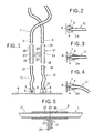
- Fig. 1 is an elevational view of a first embodiment of a device according to the present invention, wherein the various parts thereof have been shown disconnected for better understanding;
- Fig. 2 is an elevational cutaway view of a second embodiment of the connecting device for direct anti-pinching systems according to the invention;
- Fig. 3 is an elevational cutaway view of a third embodiment of the connecting device for direct anti-pinching systems according to the invention; and
- Fig. 4 is an elevational cutaway view of the embodiment of the connecting device of fig. 3 but with the section of the optical fiber slightly bent to show the action of the capsule coating extension on the optical fiber.
-
- The different references that have been used herein to describe the preferred embodiment of the device of the present invention are quoted hereinbelow:
- (1) main optical fiber conductor;
- (2) first end of the main optical fiber conductor;
- (3) second end of the main optical fiber conductor;
- (4) light emitting diode;
- (5) light receiving diode;
- (6) printed circuit board;
- (7, 8) capsules of the diodes;
- (9, 10) first end;
- (11, 12) optical fiber conductor section;
- (13, 14) second opposed end of the optical fiber conductor section;
- (15, 16) aerial connector inlets;
- (17) aerial connector;
- (18, 19) parallel hollow cylinders of the aerial connector;
- (20) traverse section of the aerial connector;
- (21, 22) opposed projections acting as a guide and stop;
- (23) external reflective coating of the capsules; and
- (24) extended conical external coating.
-
- Embodiments of a device according to the invention for connecting a sensor of a direct anti-pinching system are herein described. Such sensor comprises a main optical fiber conductor (1) fitted inside a sheath disposed along the doorframe of a motor vehicle. The sensor serves the purpose of detecting anomalies on the operation of the power window system acting, as they occur, on the mechanism of said power window system (or any other devices of similar opening) in the case of block, pinching or anomaly. The main optical fiber conductor (1) comprises a single section having a first end (2) and a second end (3).
- The connecting device of the invention essentially comprises a light emitting diode (4) and a light receiving diode (5) welded on a printed circuit board (6). The light emitting diode (4) and the light receiving diode (5) are both covered by respective capsules (7, 8).
- Each capsule (7, 8) has a cylindrical hole inside of which a first end (9, 10) is suitably inserted having two sections (11, 12) of the optical fiber connector joined to each capsule (7, 8) by means of a resin.
- The second opposed ends or free ends (13, 14) of said sections (11, 12) of the optical fiber conductor are inserted into respective inlets (15, 16) of an aerial connector (17). Said aerial connector (17) is an H-shaped connector formed of two parallel hollow cylinders (18, 19) joined by a traverse section (20).
- Inside each cylinder (18, 19) of the aerial connector (17), on the one hand, the free ends (13, 14) of the sections (11, 12) of the optical fiber conductor leaving the circuit board (6) are inserted and, on the other hand, each end (2, 3) of the main optical fiber conductor (1) of the anti-pinching system are coaxially inserted.
- The aerial connector (17) is provided, in a substantially intermediate portion within each cylinder (18, 19), with said aerial connector (17), two projections (21, 22) arranged opposed to each other acting as guide and stop for each free end (13, 14) of the sections (11, 12) of the optical fiber conductor and the ends (2, 3) of the main optical fiber conductor (1), respectively.
- In Figs. 2, 3 and 4 alternative embodiments of the connecting device for direct anti-pinching systems of the invention are shown. In the embodiment of fig. 2, capsules (7, 8) [only one of which has been herein illustrated] are provided with an external coating (23) of reflective nature coloured white, silver or similar colour with the purpose of reducing loss of light in connection.
- In the embodiment of fig. 3, capsules (7, 8) [only one of which has been illustrated] are provided with an external coating (24) extending beyond thereon disposed on the first end (9, 10) of the sections (11, 12) of the optical fiber conductor covering a part thereof. The coating (24) has an essentially progressive, conical configuration toward said first end (9, 10) of the sections (11, 12) of the optical fiber for reducing loss of light in the connection even in the case the optical fiber conductor section is bent as shown in fig. 4, thus avoiding generation of false signals.
- Once having been sufficiently described what the present patent application consists in accordance to the enclosed drawings, it is understood that any detail modification can be introduced as appropriate, provided that variations may alter the essence of the invention as summarised in the appended claims.
Claims (4)
- Device for connecting direct antipinching systems, said systems comprising sensors formed of a main optical fibre conductor (1) fitted inside a sheath and said connecting device comprising respective light emitting and receiving diodes (4, 5) mounted on a printed circuit board (6) covered by respective capsules (7, 8), characterized in that each of said capsules (7, 8) is provided with a hole inside of which one end (9, 10) of a section (11, 12) of optical fibre conductor is inserted while the second, opposed end (13, 14) of said section (11, 12) of optical fibre conductor is inserted in respective inlets (15, 16) of an aerial connector (17), said second end (13, 14)of the section (11, 12) of optical fibre conductor and the end (2, 3) of the main optical fibre conductor (1) being in contact inside said aerial connector (17).
- Device for connecting direct antipinching systems, said systems as claimed in claim 1, characterized in that said aerial connector (17) is provided, in a substantially intermediate portion therewithin, with projections (21, 22) arranged opposed to each other serving as a guide and stop for the second end (13, 14) of the section (11, 12) of the optical fibre conductor and the end (2, 3) of the main optical fibre conductor (1), respectively.
- Device for connecting direct antipinching systems, said systems as claimed in claim 1, characterized in that said capsules (7, 8) are provided with a coating (23) of reflective nature.
- Device for connecting direct antipinching systems, said systems as claimed in claim 1, characterized in that said capsules (7, 8) are provided with a coating (24) extending beyond of them on said first end (9, 10) of the section (11, 12) of the optical fibre conductor covering one part thereof.
Applications Claiming Priority (3)
| Application Number | Priority Date | Filing Date | Title |
|---|---|---|---|
| ES200200150 | 2002-01-24 | ||
| ES200200150A ES2190893B1 (en) | 2002-01-24 | 2002-01-24 | CONNECTION DEVICE FOR DIRECT ANTI-PINCHING SYSTEMS. |
| PCT/ES2003/000017 WO2003062893A1 (en) | 2002-01-24 | 2003-01-16 | Device for connecting optical fibres to light emitter and receiver circuits |
Publications (1)
| Publication Number | Publication Date |
|---|---|
| EP1469332A1 true EP1469332A1 (en) | 2004-10-20 |
Family
ID=27589311
Family Applications (1)
| Application Number | Title | Priority Date | Filing Date |
|---|---|---|---|
| EP03731724A Withdrawn EP1469332A1 (en) | 2002-01-24 | 2003-01-16 | Device for connecting optical fibres to light emitter and receiver circuits |
Country Status (4)
| Country | Link |
|---|---|
| US (1) | US7056033B2 (en) |
| EP (1) | EP1469332A1 (en) |
| ES (1) | ES2190893B1 (en) |
| WO (1) | WO2003062893A1 (en) |
Cited By (2)
| Publication number | Priority date | Publication date | Assignee | Title |
|---|---|---|---|---|
| US8493081B2 (en) | 2009-12-08 | 2013-07-23 | Magna Closures Inc. | Wide activation angle pinch sensor section and sensor hook-on attachment principle |
| US9234979B2 (en) | 2009-12-08 | 2016-01-12 | Magna Closures Inc. | Wide activation angle pinch sensor section |
Families Citing this family (3)
| Publication number | Priority date | Publication date | Assignee | Title |
|---|---|---|---|---|
| DE102004027034B4 (en) * | 2004-06-02 | 2006-03-30 | Molex Inc., Lisle | Optical connector assembly |
| US7806602B2 (en) * | 2008-03-14 | 2010-10-05 | Finisar Corporation | Optical micro-connector |
| DE102018001391A1 (en) * | 2018-02-21 | 2019-08-22 | Huf Hülsbeck & Fürst GmbH & Co KG | Optical sensor system of a motor vehicle for detecting operating gestures |
Family Cites Families (9)
| Publication number | Priority date | Publication date | Assignee | Title |
|---|---|---|---|---|
| US4118100A (en) * | 1975-12-10 | 1978-10-03 | International Telephone And Telegraph Corporation | Optical couplers for light emitting diodes and detectors |
| FR2405488A1 (en) | 1977-10-07 | 1979-05-04 | Radiotechnique Compelec | OPTICAL DEVICE FOR A CONNECTOR INTENDED FOR TRANSMISSION BY FIBERS AND ITS EMBODIMENT METHOD |
| US5032898A (en) * | 1979-12-10 | 1991-07-16 | Amp Incorporated | Electro-optic device assembly having integral heat sink/retention means |
| JPS59128009A (en) * | 1983-01-10 | 1984-07-24 | Nippon Denso Co Ltd | Safety device for automatic opening/closing apparatus |
| US5631987A (en) * | 1995-06-07 | 1997-05-20 | Reliaspeed, Inc. | Low cost, mode-field matched, high performance laser transmitter optical subassembly |
| JP2001330757A (en) * | 2000-05-23 | 2001-11-30 | Yazaki Corp | Optical connector |
| US6932516B2 (en) * | 2000-07-19 | 2005-08-23 | Canon Kabushiki Kaisha | Surface optical device apparatus, method of fabricating the same, and apparatus using the same |
| JP3921940B2 (en) * | 2000-12-07 | 2007-05-30 | 住友電気工業株式会社 | Optical transceiver module |
| US6692161B2 (en) * | 2001-03-29 | 2004-02-17 | Intel Corporation | High frequency emitter and detector packaging scheme for 10GB/S transceiver |
-
2002
- 2002-01-24 ES ES200200150A patent/ES2190893B1/en not_active Expired - Fee Related
-
2003
- 2003-01-16 US US10/477,464 patent/US7056033B2/en not_active Expired - Lifetime
- 2003-01-16 WO PCT/ES2003/000017 patent/WO2003062893A1/en active Application Filing
- 2003-01-16 EP EP03731724A patent/EP1469332A1/en not_active Withdrawn
Non-Patent Citations (1)
| Title |
|---|
| See references of WO03062893A1 * |
Cited By (3)
| Publication number | Priority date | Publication date | Assignee | Title |
|---|---|---|---|---|
| US8493081B2 (en) | 2009-12-08 | 2013-07-23 | Magna Closures Inc. | Wide activation angle pinch sensor section and sensor hook-on attachment principle |
| US9234979B2 (en) | 2009-12-08 | 2016-01-12 | Magna Closures Inc. | Wide activation angle pinch sensor section |
| US9417099B2 (en) | 2009-12-08 | 2016-08-16 | Magna Closures Inc. | Wide activation angle pinch sensor section |
Also Published As
| Publication number | Publication date |
|---|---|
| US7056033B2 (en) | 2006-06-06 |
| US20040136659A1 (en) | 2004-07-15 |
| ES2190893B1 (en) | 2004-06-01 |
| WO2003062893A1 (en) | 2003-07-31 |
| ES2190893A1 (en) | 2003-08-16 |
Similar Documents
| Publication | Publication Date | Title |
|---|---|---|
| US6536959B2 (en) | Coupling configuration for connecting an optical fiber to an optoelectronic component | |
| US5146516A (en) | Optoelectrical sending and receiving apparatus | |
| US5064299A (en) | Optocoupler apparatus | |
| EP0770893A3 (en) | Optical fiber locking submount and hermetic feedthrough assembly | |
| WO2001000443A1 (en) | Vehicular puddle light | |
| KR970000867A (en) | Vehicle end side check device | |
| CA2126376A1 (en) | Optical waveguide module | |
| EP1469332A1 (en) | Device for connecting optical fibres to light emitter and receiver circuits | |
| US20030059178A1 (en) | Bidirectional optical transmission device | |
| EP0957334A3 (en) | Photoelectric switch, fiber-type photoelectric switch, and color discrimination sensor | |
| US7220062B2 (en) | Active bulkhead transceiver | |
| EP0452475B1 (en) | Optical fiber coupler | |
| EP0887674A3 (en) | Optical transmitter/receiver apparatus, method for fabricating the same and optical semiconductor module | |
| US7660497B2 (en) | Apparatus for transmitting optical signals between components which can be rotated relative to one another (rotary transmitter) | |
| US5889284A (en) | Liquid level gauge having p-c board enclosed within probe | |
| JPH0246113B2 (en) | ||
| US6655849B1 (en) | Optical connector, particularly for operating in high pressure environment | |
| WO2003029868A1 (en) | Optical transmitter/receiver | |
| US8084731B2 (en) | Sensor system for liquid detection with lens component having an apex | |
| CN210083069U (en) | Light scattering component, blind area detection alarm device and rearview mirror | |
| JPH0339746Y2 (en) | ||
| JPH0265078A (en) | Defective coupling detecting device for connector for automobile | |
| JPS635579A (en) | Optical connector module | |
| US20030231503A1 (en) | Lighting generating optical fiber cables system | |
| CN210083070U (en) | Light source connecting assembly, blind area detection alarm device and rearview mirror |
Legal Events
| Date | Code | Title | Description |
|---|---|---|---|
| PUAI | Public reference made under article 153(3) epc to a published international application that has entered the european phase |
Free format text: ORIGINAL CODE: 0009012 |
|
| 17P | Request for examination filed |
Effective date: 20031016 |
|
| AK | Designated contracting states |
Kind code of ref document: A1 Designated state(s): AT BE BG CH CY CZ DE DK EE ES FI FR GB GR HU IE IT LI LU MC NL PT SE SI SK TR |
|
| 17Q | First examination report despatched |
Effective date: 20060807 |
|
| GRAP | Despatch of communication of intention to grant a patent |
Free format text: ORIGINAL CODE: EPIDOSNIGR1 |
|
| STAA | Information on the status of an ep patent application or granted ep patent |
Free format text: STATUS: THE APPLICATION IS DEEMED TO BE WITHDRAWN |
|
| 18D | Application deemed to be withdrawn |
Effective date: 20120301 |