EP1469265B1 - Process for nitrogen liquefaction by recovering the cold derived from liquid methane gasification - Google Patents
Process for nitrogen liquefaction by recovering the cold derived from liquid methane gasification Download PDFInfo
- Publication number
- EP1469265B1 EP1469265B1 EP04007031A EP04007031A EP1469265B1 EP 1469265 B1 EP1469265 B1 EP 1469265B1 EP 04007031 A EP04007031 A EP 04007031A EP 04007031 A EP04007031 A EP 04007031A EP 1469265 B1 EP1469265 B1 EP 1469265B1
- Authority
- EP
- European Patent Office
- Prior art keywords
- cryogenic fluid
- nitrogen
- coolers
- heat exchanger
- cooling
- Prior art date
- Legal status (The legal status is an assumption and is not a legal conclusion. Google has not performed a legal analysis and makes no representation as to the accuracy of the status listed.)
- Expired - Lifetime
Links
- IJGRMHOSHXDMSA-UHFFFAOYSA-N Atomic nitrogen Chemical compound N#N IJGRMHOSHXDMSA-UHFFFAOYSA-N 0.000 title claims abstract description 86
- VNWKTOKETHGBQD-UHFFFAOYSA-N methane Chemical compound C VNWKTOKETHGBQD-UHFFFAOYSA-N 0.000 title claims abstract description 70
- 229910052757 nitrogen Inorganic materials 0.000 title claims abstract description 44
- 239000007788 liquid Substances 0.000 title claims abstract description 31
- 238000000034 method Methods 0.000 title claims abstract description 19
- 238000002309 gasification Methods 0.000 title claims abstract description 6
- 239000012530 fluid Substances 0.000 claims abstract description 28
- 238000001816 cooling Methods 0.000 claims abstract description 15
- 239000002826 coolant Substances 0.000 claims abstract 3
- XKRFYHLGVUSROY-UHFFFAOYSA-N Argon Chemical compound [Ar] XKRFYHLGVUSROY-UHFFFAOYSA-N 0.000 claims description 6
- 229910052786 argon Inorganic materials 0.000 claims description 3
- 238000004519 manufacturing process Methods 0.000 claims description 3
- MYMOFIZGZYHOMD-UHFFFAOYSA-N Dioxygen Chemical compound O=O MYMOFIZGZYHOMD-UHFFFAOYSA-N 0.000 claims description 2
- 238000005194 fractionation Methods 0.000 claims description 2
- 238000005265 energy consumption Methods 0.000 abstract description 6
- 239000007789 gas Substances 0.000 description 6
- 238000007906 compression Methods 0.000 description 3
- 230000006835 compression Effects 0.000 description 3
- XLYOFNOQVPJJNP-UHFFFAOYSA-N water Substances O XLYOFNOQVPJJNP-UHFFFAOYSA-N 0.000 description 3
- 238000010438 heat treatment Methods 0.000 description 2
- 150000002829 nitrogen Chemical class 0.000 description 2
- 238000009834 vaporization Methods 0.000 description 2
- 230000008016 vaporization Effects 0.000 description 2
- 238000010521 absorption reaction Methods 0.000 description 1
- QVGXLLKOCUKJST-UHFFFAOYSA-N atomic oxygen Chemical compound [O] QVGXLLKOCUKJST-UHFFFAOYSA-N 0.000 description 1
- 230000007423 decrease Effects 0.000 description 1
- 238000009413 insulation Methods 0.000 description 1
- 239000001301 oxygen Substances 0.000 description 1
- 229910052760 oxygen Inorganic materials 0.000 description 1
- 230000000750 progressive effect Effects 0.000 description 1
- 238000011084 recovery Methods 0.000 description 1
- 238000005057 refrigeration Methods 0.000 description 1
- 238000011144 upstream manufacturing Methods 0.000 description 1
Images
Classifications
-
- F—MECHANICAL ENGINEERING; LIGHTING; HEATING; WEAPONS; BLASTING
- F25—REFRIGERATION OR COOLING; COMBINED HEATING AND REFRIGERATION SYSTEMS; HEAT PUMP SYSTEMS; MANUFACTURE OR STORAGE OF ICE; LIQUEFACTION SOLIDIFICATION OF GASES
- F25J—LIQUEFACTION, SOLIDIFICATION OR SEPARATION OF GASES OR GASEOUS OR LIQUEFIED GASEOUS MIXTURES BY PRESSURE AND COLD TREATMENT OR BY BRINGING THEM INTO THE SUPERCRITICAL STATE
- F25J1/00—Processes or apparatus for liquefying or solidifying gases or gaseous mixtures
- F25J1/02—Processes or apparatus for liquefying or solidifying gases or gaseous mixtures requiring the use of refrigeration, e.g. of helium or hydrogen ; Details and kind of the refrigeration system used; Integration with other units or processes; Controlling aspects of the process
- F25J1/0203—Processes or apparatus for liquefying or solidifying gases or gaseous mixtures requiring the use of refrigeration, e.g. of helium or hydrogen ; Details and kind of the refrigeration system used; Integration with other units or processes; Controlling aspects of the process using a single-component refrigerant [SCR] fluid in a closed vapor compression cycle
- F25J1/0204—Processes or apparatus for liquefying or solidifying gases or gaseous mixtures requiring the use of refrigeration, e.g. of helium or hydrogen ; Details and kind of the refrigeration system used; Integration with other units or processes; Controlling aspects of the process using a single-component refrigerant [SCR] fluid in a closed vapor compression cycle as a single flow SCR cycle
-
- F—MECHANICAL ENGINEERING; LIGHTING; HEATING; WEAPONS; BLASTING
- F25—REFRIGERATION OR COOLING; COMBINED HEATING AND REFRIGERATION SYSTEMS; HEAT PUMP SYSTEMS; MANUFACTURE OR STORAGE OF ICE; LIQUEFACTION SOLIDIFICATION OF GASES
- F25J—LIQUEFACTION, SOLIDIFICATION OR SEPARATION OF GASES OR GASEOUS OR LIQUEFIED GASEOUS MIXTURES BY PRESSURE AND COLD TREATMENT OR BY BRINGING THEM INTO THE SUPERCRITICAL STATE
- F25J1/00—Processes or apparatus for liquefying or solidifying gases or gaseous mixtures
- F25J1/0002—Processes or apparatus for liquefying or solidifying gases or gaseous mixtures characterised by the fluid to be liquefied
- F25J1/0012—Primary atmospheric gases, e.g. air
- F25J1/0015—Nitrogen
-
- F—MECHANICAL ENGINEERING; LIGHTING; HEATING; WEAPONS; BLASTING
- F25—REFRIGERATION OR COOLING; COMBINED HEATING AND REFRIGERATION SYSTEMS; HEAT PUMP SYSTEMS; MANUFACTURE OR STORAGE OF ICE; LIQUEFACTION SOLIDIFICATION OF GASES
- F25J—LIQUEFACTION, SOLIDIFICATION OR SEPARATION OF GASES OR GASEOUS OR LIQUEFIED GASEOUS MIXTURES BY PRESSURE AND COLD TREATMENT OR BY BRINGING THEM INTO THE SUPERCRITICAL STATE
- F25J1/00—Processes or apparatus for liquefying or solidifying gases or gaseous mixtures
- F25J1/003—Processes or apparatus for liquefying or solidifying gases or gaseous mixtures characterised by the kind of cold generation within the liquefaction unit for compensating heat leaks and liquid production
- F25J1/0047—Processes or apparatus for liquefying or solidifying gases or gaseous mixtures characterised by the kind of cold generation within the liquefaction unit for compensating heat leaks and liquid production using an "external" refrigerant stream in a closed vapor compression cycle
- F25J1/005—Processes or apparatus for liquefying or solidifying gases or gaseous mixtures characterised by the kind of cold generation within the liquefaction unit for compensating heat leaks and liquid production using an "external" refrigerant stream in a closed vapor compression cycle by expansion of a gaseous refrigerant stream with extraction of work
-
- F—MECHANICAL ENGINEERING; LIGHTING; HEATING; WEAPONS; BLASTING
- F25—REFRIGERATION OR COOLING; COMBINED HEATING AND REFRIGERATION SYSTEMS; HEAT PUMP SYSTEMS; MANUFACTURE OR STORAGE OF ICE; LIQUEFACTION SOLIDIFICATION OF GASES
- F25J—LIQUEFACTION, SOLIDIFICATION OR SEPARATION OF GASES OR GASEOUS OR LIQUEFIED GASEOUS MIXTURES BY PRESSURE AND COLD TREATMENT OR BY BRINGING THEM INTO THE SUPERCRITICAL STATE
- F25J1/00—Processes or apparatus for liquefying or solidifying gases or gaseous mixtures
- F25J1/006—Processes or apparatus for liquefying or solidifying gases or gaseous mixtures characterised by the refrigerant fluid used
- F25J1/007—Primary atmospheric gases, mixtures thereof
- F25J1/0072—Nitrogen
-
- F—MECHANICAL ENGINEERING; LIGHTING; HEATING; WEAPONS; BLASTING
- F25—REFRIGERATION OR COOLING; COMBINED HEATING AND REFRIGERATION SYSTEMS; HEAT PUMP SYSTEMS; MANUFACTURE OR STORAGE OF ICE; LIQUEFACTION SOLIDIFICATION OF GASES
- F25J—LIQUEFACTION, SOLIDIFICATION OR SEPARATION OF GASES OR GASEOUS OR LIQUEFIED GASEOUS MIXTURES BY PRESSURE AND COLD TREATMENT OR BY BRINGING THEM INTO THE SUPERCRITICAL STATE
- F25J1/00—Processes or apparatus for liquefying or solidifying gases or gaseous mixtures
- F25J1/02—Processes or apparatus for liquefying or solidifying gases or gaseous mixtures requiring the use of refrigeration, e.g. of helium or hydrogen ; Details and kind of the refrigeration system used; Integration with other units or processes; Controlling aspects of the process
- F25J1/0221—Processes or apparatus for liquefying or solidifying gases or gaseous mixtures requiring the use of refrigeration, e.g. of helium or hydrogen ; Details and kind of the refrigeration system used; Integration with other units or processes; Controlling aspects of the process using the cold stored in an external cryogenic component in an open refrigeration loop
- F25J1/0222—Processes or apparatus for liquefying or solidifying gases or gaseous mixtures requiring the use of refrigeration, e.g. of helium or hydrogen ; Details and kind of the refrigeration system used; Integration with other units or processes; Controlling aspects of the process using the cold stored in an external cryogenic component in an open refrigeration loop in combination with an intermediate heat exchange fluid between the cryogenic component and the fluid to be liquefied
-
- F—MECHANICAL ENGINEERING; LIGHTING; HEATING; WEAPONS; BLASTING
- F25—REFRIGERATION OR COOLING; COMBINED HEATING AND REFRIGERATION SYSTEMS; HEAT PUMP SYSTEMS; MANUFACTURE OR STORAGE OF ICE; LIQUEFACTION SOLIDIFICATION OF GASES
- F25J—LIQUEFACTION, SOLIDIFICATION OR SEPARATION OF GASES OR GASEOUS OR LIQUEFIED GASEOUS MIXTURES BY PRESSURE AND COLD TREATMENT OR BY BRINGING THEM INTO THE SUPERCRITICAL STATE
- F25J1/00—Processes or apparatus for liquefying or solidifying gases or gaseous mixtures
- F25J1/02—Processes or apparatus for liquefying or solidifying gases or gaseous mixtures requiring the use of refrigeration, e.g. of helium or hydrogen ; Details and kind of the refrigeration system used; Integration with other units or processes; Controlling aspects of the process
- F25J1/0228—Coupling of the liquefaction unit to other units or processes, so-called integrated processes
- F25J1/0234—Integration with a cryogenic air separation unit
-
- F—MECHANICAL ENGINEERING; LIGHTING; HEATING; WEAPONS; BLASTING
- F25—REFRIGERATION OR COOLING; COMBINED HEATING AND REFRIGERATION SYSTEMS; HEAT PUMP SYSTEMS; MANUFACTURE OR STORAGE OF ICE; LIQUEFACTION SOLIDIFICATION OF GASES
- F25J—LIQUEFACTION, SOLIDIFICATION OR SEPARATION OF GASES OR GASEOUS OR LIQUEFIED GASEOUS MIXTURES BY PRESSURE AND COLD TREATMENT OR BY BRINGING THEM INTO THE SUPERCRITICAL STATE
- F25J1/00—Processes or apparatus for liquefying or solidifying gases or gaseous mixtures
- F25J1/02—Processes or apparatus for liquefying or solidifying gases or gaseous mixtures requiring the use of refrigeration, e.g. of helium or hydrogen ; Details and kind of the refrigeration system used; Integration with other units or processes; Controlling aspects of the process
- F25J1/0243—Start-up or control of the process; Details of the apparatus used; Details of the refrigerant compression system used
- F25J1/0257—Construction and layout of liquefaction equipments, e.g. valves, machines
- F25J1/0262—Details of the cold heat exchange system
- F25J1/0264—Arrangement of heat exchanger cores in parallel with different functions, e.g. different cooling streams
- F25J1/0265—Arrangement of heat exchanger cores in parallel with different functions, e.g. different cooling streams comprising cores associated exclusively with the cooling of a refrigerant stream, e.g. for auto-refrigeration or economizer
- F25J1/0268—Arrangement of heat exchanger cores in parallel with different functions, e.g. different cooling streams comprising cores associated exclusively with the cooling of a refrigerant stream, e.g. for auto-refrigeration or economizer using a dedicated refrigeration means
-
- F—MECHANICAL ENGINEERING; LIGHTING; HEATING; WEAPONS; BLASTING
- F25—REFRIGERATION OR COOLING; COMBINED HEATING AND REFRIGERATION SYSTEMS; HEAT PUMP SYSTEMS; MANUFACTURE OR STORAGE OF ICE; LIQUEFACTION SOLIDIFICATION OF GASES
- F25J—LIQUEFACTION, SOLIDIFICATION OR SEPARATION OF GASES OR GASEOUS OR LIQUEFIED GASEOUS MIXTURES BY PRESSURE AND COLD TREATMENT OR BY BRINGING THEM INTO THE SUPERCRITICAL STATE
- F25J1/00—Processes or apparatus for liquefying or solidifying gases or gaseous mixtures
- F25J1/02—Processes or apparatus for liquefying or solidifying gases or gaseous mixtures requiring the use of refrigeration, e.g. of helium or hydrogen ; Details and kind of the refrigeration system used; Integration with other units or processes; Controlling aspects of the process
- F25J1/0243—Start-up or control of the process; Details of the apparatus used; Details of the refrigerant compression system used
- F25J1/0279—Compression of refrigerant or internal recycle fluid, e.g. kind of compressor, accumulator, suction drum etc.
- F25J1/0292—Refrigerant compression by cold or cryogenic suction of the refrigerant gas
-
- F—MECHANICAL ENGINEERING; LIGHTING; HEATING; WEAPONS; BLASTING
- F25—REFRIGERATION OR COOLING; COMBINED HEATING AND REFRIGERATION SYSTEMS; HEAT PUMP SYSTEMS; MANUFACTURE OR STORAGE OF ICE; LIQUEFACTION SOLIDIFICATION OF GASES
- F25J—LIQUEFACTION, SOLIDIFICATION OR SEPARATION OF GASES OR GASEOUS OR LIQUEFIED GASEOUS MIXTURES BY PRESSURE AND COLD TREATMENT OR BY BRINGING THEM INTO THE SUPERCRITICAL STATE
- F25J1/00—Processes or apparatus for liquefying or solidifying gases or gaseous mixtures
- F25J1/02—Processes or apparatus for liquefying or solidifying gases or gaseous mixtures requiring the use of refrigeration, e.g. of helium or hydrogen ; Details and kind of the refrigeration system used; Integration with other units or processes; Controlling aspects of the process
- F25J1/0243—Start-up or control of the process; Details of the apparatus used; Details of the refrigerant compression system used
- F25J1/0279—Compression of refrigerant or internal recycle fluid, e.g. kind of compressor, accumulator, suction drum etc.
- F25J1/0296—Removal of the heat of compression, e.g. within an inter- or afterstage-cooler against an ambient heat sink
- F25J1/0297—Removal of the heat of compression, e.g. within an inter- or afterstage-cooler against an ambient heat sink using an externally chilled fluid, e.g. chilled water
-
- F—MECHANICAL ENGINEERING; LIGHTING; HEATING; WEAPONS; BLASTING
- F25—REFRIGERATION OR COOLING; COMBINED HEATING AND REFRIGERATION SYSTEMS; HEAT PUMP SYSTEMS; MANUFACTURE OR STORAGE OF ICE; LIQUEFACTION SOLIDIFICATION OF GASES
- F25J—LIQUEFACTION, SOLIDIFICATION OR SEPARATION OF GASES OR GASEOUS OR LIQUEFIED GASEOUS MIXTURES BY PRESSURE AND COLD TREATMENT OR BY BRINGING THEM INTO THE SUPERCRITICAL STATE
- F25J3/00—Processes or apparatus for separating the constituents of gaseous or liquefied gaseous mixtures involving the use of liquefaction or solidification
- F25J3/02—Processes or apparatus for separating the constituents of gaseous or liquefied gaseous mixtures involving the use of liquefaction or solidification by rectification, i.e. by continuous interchange of heat and material between a vapour stream and a liquid stream
- F25J3/04—Processes or apparatus for separating the constituents of gaseous or liquefied gaseous mixtures involving the use of liquefaction or solidification by rectification, i.e. by continuous interchange of heat and material between a vapour stream and a liquid stream for air
- F25J3/04006—Providing pressurised feed air or process streams within or from the air fractionation unit
- F25J3/04048—Providing pressurised feed air or process streams within or from the air fractionation unit by compression of cold gaseous streams, e.g. intermediate or oxygen enriched (waste) streams
- F25J3/0406—Providing pressurised feed air or process streams within or from the air fractionation unit by compression of cold gaseous streams, e.g. intermediate or oxygen enriched (waste) streams of nitrogen
-
- F—MECHANICAL ENGINEERING; LIGHTING; HEATING; WEAPONS; BLASTING
- F25—REFRIGERATION OR COOLING; COMBINED HEATING AND REFRIGERATION SYSTEMS; HEAT PUMP SYSTEMS; MANUFACTURE OR STORAGE OF ICE; LIQUEFACTION SOLIDIFICATION OF GASES
- F25J—LIQUEFACTION, SOLIDIFICATION OR SEPARATION OF GASES OR GASEOUS OR LIQUEFIED GASEOUS MIXTURES BY PRESSURE AND COLD TREATMENT OR BY BRINGING THEM INTO THE SUPERCRITICAL STATE
- F25J3/00—Processes or apparatus for separating the constituents of gaseous or liquefied gaseous mixtures involving the use of liquefaction or solidification
- F25J3/02—Processes or apparatus for separating the constituents of gaseous or liquefied gaseous mixtures involving the use of liquefaction or solidification by rectification, i.e. by continuous interchange of heat and material between a vapour stream and a liquid stream
- F25J3/04—Processes or apparatus for separating the constituents of gaseous or liquefied gaseous mixtures involving the use of liquefaction or solidification by rectification, i.e. by continuous interchange of heat and material between a vapour stream and a liquid stream for air
- F25J3/04248—Generation of cold for compensating heat leaks or liquid production, e.g. by Joule-Thompson expansion
- F25J3/04254—Generation of cold for compensating heat leaks or liquid production, e.g. by Joule-Thompson expansion using the cold stored in external cryogenic fluids
-
- F—MECHANICAL ENGINEERING; LIGHTING; HEATING; WEAPONS; BLASTING
- F25—REFRIGERATION OR COOLING; COMBINED HEATING AND REFRIGERATION SYSTEMS; HEAT PUMP SYSTEMS; MANUFACTURE OR STORAGE OF ICE; LIQUEFACTION SOLIDIFICATION OF GASES
- F25J—LIQUEFACTION, SOLIDIFICATION OR SEPARATION OF GASES OR GASEOUS OR LIQUEFIED GASEOUS MIXTURES BY PRESSURE AND COLD TREATMENT OR BY BRINGING THEM INTO THE SUPERCRITICAL STATE
- F25J3/00—Processes or apparatus for separating the constituents of gaseous or liquefied gaseous mixtures involving the use of liquefaction or solidification
- F25J3/02—Processes or apparatus for separating the constituents of gaseous or liquefied gaseous mixtures involving the use of liquefaction or solidification by rectification, i.e. by continuous interchange of heat and material between a vapour stream and a liquid stream
- F25J3/04—Processes or apparatus for separating the constituents of gaseous or liquefied gaseous mixtures involving the use of liquefaction or solidification by rectification, i.e. by continuous interchange of heat and material between a vapour stream and a liquid stream for air
- F25J3/04248—Generation of cold for compensating heat leaks or liquid production, e.g. by Joule-Thompson expansion
- F25J3/04333—Generation of cold for compensating heat leaks or liquid production, e.g. by Joule-Thompson expansion using quasi-closed loop internal vapor compression refrigeration cycles, e.g. of intermediate or oxygen enriched (waste-)streams
- F25J3/04351—Generation of cold for compensating heat leaks or liquid production, e.g. by Joule-Thompson expansion using quasi-closed loop internal vapor compression refrigeration cycles, e.g. of intermediate or oxygen enriched (waste-)streams of nitrogen
-
- F—MECHANICAL ENGINEERING; LIGHTING; HEATING; WEAPONS; BLASTING
- F25—REFRIGERATION OR COOLING; COMBINED HEATING AND REFRIGERATION SYSTEMS; HEAT PUMP SYSTEMS; MANUFACTURE OR STORAGE OF ICE; LIQUEFACTION SOLIDIFICATION OF GASES
- F25J—LIQUEFACTION, SOLIDIFICATION OR SEPARATION OF GASES OR GASEOUS OR LIQUEFIED GASEOUS MIXTURES BY PRESSURE AND COLD TREATMENT OR BY BRINGING THEM INTO THE SUPERCRITICAL STATE
- F25J2210/00—Processes characterised by the type or other details of the feed stream
- F25J2210/62—Liquefied natural gas [LNG]; Natural gas liquids [NGL]; Liquefied petroleum gas [LPG]
-
- F—MECHANICAL ENGINEERING; LIGHTING; HEATING; WEAPONS; BLASTING
- F25—REFRIGERATION OR COOLING; COMBINED HEATING AND REFRIGERATION SYSTEMS; HEAT PUMP SYSTEMS; MANUFACTURE OR STORAGE OF ICE; LIQUEFACTION SOLIDIFICATION OF GASES
- F25J—LIQUEFACTION, SOLIDIFICATION OR SEPARATION OF GASES OR GASEOUS OR LIQUEFIED GASEOUS MIXTURES BY PRESSURE AND COLD TREATMENT OR BY BRINGING THEM INTO THE SUPERCRITICAL STATE
- F25J2230/00—Processes or apparatus involving steps for increasing the pressure of gaseous process streams
- F25J2230/08—Cold compressor, i.e. suction of the gas at cryogenic temperature and generally without afterstage-cooler
-
- F—MECHANICAL ENGINEERING; LIGHTING; HEATING; WEAPONS; BLASTING
- F25—REFRIGERATION OR COOLING; COMBINED HEATING AND REFRIGERATION SYSTEMS; HEAT PUMP SYSTEMS; MANUFACTURE OR STORAGE OF ICE; LIQUEFACTION SOLIDIFICATION OF GASES
- F25J—LIQUEFACTION, SOLIDIFICATION OR SEPARATION OF GASES OR GASEOUS OR LIQUEFIED GASEOUS MIXTURES BY PRESSURE AND COLD TREATMENT OR BY BRINGING THEM INTO THE SUPERCRITICAL STATE
- F25J2230/00—Processes or apparatus involving steps for increasing the pressure of gaseous process streams
- F25J2230/30—Compression of the feed stream
-
- F—MECHANICAL ENGINEERING; LIGHTING; HEATING; WEAPONS; BLASTING
- F25—REFRIGERATION OR COOLING; COMBINED HEATING AND REFRIGERATION SYSTEMS; HEAT PUMP SYSTEMS; MANUFACTURE OR STORAGE OF ICE; LIQUEFACTION SOLIDIFICATION OF GASES
- F25J—LIQUEFACTION, SOLIDIFICATION OR SEPARATION OF GASES OR GASEOUS OR LIQUEFIED GASEOUS MIXTURES BY PRESSURE AND COLD TREATMENT OR BY BRINGING THEM INTO THE SUPERCRITICAL STATE
- F25J2230/00—Processes or apparatus involving steps for increasing the pressure of gaseous process streams
- F25J2230/42—Processes or apparatus involving steps for increasing the pressure of gaseous process streams the fluid being nitrogen
Definitions
- This invention relates to a process and apparatus for liquefying a cryogenic fluid comprising the features of the preamble of claims 1 and 4.
- Such a process, respectively apparatus is known from JP 02 171 580 A and EP 1 055 894 A.
- methane tankers specialized for this purpose have to be used.
- these tankers are designed to transport it in liquid form in order to reduce its volume.
- the methane has to be maintained at cryogenic temperature, the value of which depends on the storage pressure (for example -154°C at 2 bar absolute).
- methane tankers the methane is contained in suitable tanks under high thermal insulation (using the Dewar flask principle).
- this methane On reaching land, this methane has to be transported or used in gaseous form, and must therefore be vaporized and heated. To express this concept in other words, it could be said that in order to undergo vaporization and heating, it must transfer its "cold” to another fluid, which hence itself becomes cold during said heat transfer.
- thermodynamic refrigeration cycles it is known that to cool a gas to a temperature less than the temperature of the environment in which it is present requires considerable energy consumption related to the application of usual thermodynamic refrigeration cycles.
- this energy consumption is imposed by the need to compress the gas to be liquefied so that it becomes hot, and then to extract from it the heat associated with the temperature increase deriving from this compression more efficiently as it is effected at a higher temperature level.
- Subsequent expansion of the compressed and cooled gas in a turbine further reduces its temperature to cryogenic values, with resultant liquefaction of the gas.
- liquid methane transported by methane tankers contains a "negative energy" or cold, which it would be extremely advantageous to recover.
- one of the usual methods of heating liquid methane is to pass the liquid methane through a heat exchanger through which water circulates in counter-current to heat said methane from a temperature of-150°C to a temperature of +15°C.
- this gasification method alters the ecosystem as it causes artificial intermittent cooling of the sea.
- the known art uses the said cold mainly during cooling by suitable heat exchangers.
- An object of the present invention is to define a process for using the cold deriving from liquid methane gasification which is more advantageous than those currently used. In accordance with the present invention this object is solved by the characterizing features of claims 1 and 4.
- a liquid methane inlet line 1 leads to a pump 2.
- the pump 2 (indicatively of centrifugal type) feeds the liquid methane to a heat exchanger 4, which subtracts heat from a line 5 through which nitrogen passes in counter-current.
- This nitrogen originates from another heat exchanger 6 in which a water line 7 had previously raised its temperature from about -98°C to about -34°C.
- Said nitrogen is maintained at a relatively high pressure to increase the temperature difference between the methane and nitrogen in order, other conditions being equal, to achieve greater absorption of the cold provided by the liquid methane.
- the nitrogen cooled in this manner by heat transfer with liquid methane leaves the heat exchanger 4 through a line 8, which branches into two lines 9 and 10 to enable the cold of the nitrogen to be used to cool the nitrogen circulating within specific circuits 18, 20 of the apparatus in which said nitrogen is liquefied.
- the line 9 conveys the cold withdrawn from the methane to the interstage coolers (heat exchangers) 11, 12, 13 located respectively at the outlet of three stages 16, 15, 14 of a conventional compressor unit for the nitrogen in the circuit 18, which is of closed type.
- the nitrogen of the closed circuit 18, cooled in this manner has a pressure of about 10 bar and a temperature of about -141°C.
- the nitrogen cooled in this manner in the closed circuit 18, passes through a heat exchanger 19 to absorb heat from the nitrogen compressed in an open circuit 20.
- This open circuit 20 comprises an inlet line 21, into which gaseous nitrogen is fed at a pressure of 1.15 bar absolute and a temperature of +15°C.
- This nitrogen undergoes successive compressions by a compressor unit composed of a first stage 22, a second stage 23, a third stage 24, a fourth stage 25 and a fifth stage 26.
- the nitrogen of the open circuit 20 undergoes the following cooling sequence: cooling implemented by an intake heat exchanger 27, cooling implemented by a plurality of interstage heat exchangers (28, 29, 30, 31) and further cooling implemented by a final heat exchanger 32 upstream of said heat exchanger 19 located in the final part of said open circuit 20.
- Said heat exchangers 27, 28, 29, 30, 31 32 subtract heat from the nitrogen of the open circuit 20 by transferring to it the cold present in the nitrogen passing through the line 10, itself cooled by the cold subtracted from the liquid methane in the heat exchanger 4.
- the nitrogen of the two lines 9 and 10 flows into a common line 33, through which the nitrogen is fed to a compressor 34 which circulates it at a pressure of about 70 bar along the paths already described and in the directions indicated by the arrows.
- the nitrogen enters the open circuit 20 in the gaseous state through the line 21 and leaves in the liquid state through a line 3, by optimum use of the cold deriving from the vaporization of the liquid methane.
- liquid nitrogen produced in this manner can itself be used in the usual air fractionation plants to produce liquid oxygen, nitrogen and argon, and in addition for all the usual possible uses of liquid nitrogen.
- the process for recovering cold from liquid methane by liquid nitrogen production cycles in the aforedescribed manner results in substantial energy savings.
Abstract
Description
- This invention relates to a process and apparatus for liquefying a cryogenic fluid comprising the features of the preamble of
claims 1 and 4. Such a process, respectively apparatus, is known from JP 02 171 580 A and EP 1 055 894 A. - As methane has to be obtained from many regions of the world, it is not always possible to use usual methane pipelines, and instead methane tankers specialized for this purpose have to be used.
- To be able to transport the maximum quantity of methane, these tankers are designed to transport it in liquid form in order to reduce its volume. However to remain in the liquid state, the methane has to be maintained at cryogenic temperature, the value of which depends on the storage pressure (for example -154°C at 2 bar absolute).
- In methane tankers the methane is contained in suitable tanks under high thermal insulation (using the Dewar flask principle).
- On reaching land, this methane has to be transported or used in gaseous form, and must therefore be vaporized and heated. To express this concept in other words, it could be said that in order to undergo vaporization and heating, it must transfer its "cold" to another fluid, which hence itself becomes cold during said heat transfer.
- In this respect, it is known that to cool a gas to a temperature less than the temperature of the environment in which it is present requires considerable energy consumption related to the application of usual thermodynamic refrigeration cycles.
- Substantially, this energy consumption is imposed by the need to compress the gas to be liquefied so that it becomes hot, and then to extract from it the heat associated with the temperature increase deriving from this compression more efficiently as it is effected at a higher temperature level. Subsequent expansion of the compressed and cooled gas in a turbine further reduces its temperature to cryogenic values, with resultant liquefaction of the gas.
- Hence on this basis, liquid methane transported by methane tankers contains a "negative energy" or cold, which it would be extremely advantageous to recover.
- In this respect, one of the usual methods of heating liquid methane is to pass the liquid methane through a heat exchanger through which water circulates in counter-current to heat said methane from a temperature of-150°C to a temperature of +15°C.
- Besides not providing any energy recovery, this gasification method alters the ecosystem as it causes artificial intermittent cooling of the sea.
- This is because the water used to heat the methane is withdrawn from the sea, cooled and then returned to the sea at a temperature lower than that at which it was withdrawn.
- Because of the progressive importance assumed by methane traffic, current research is aimed at recovering the cold possessed by liquid methane in liquid air production cycles (Linde machine, Claude machine).
- These cycles consist of repeated compression, cooling and expansion until the air becomes liquid at a temperature of -195°C.
- More specifically, the known art uses the said cold mainly during cooling by suitable heat exchangers.
- However this known art does not provide a technical basis suitable for using the said cold offered by liquid methane in a manner able to reduce the energy consumption relating to the cooling and liquefaction of technical gases normally used in industry (nitrogen, oxygen, argon).
- To illustrate these concepts with numerical examples, expressive of current industrial reality, 13,000 kWh are required to liquefy 25,000 Normal (atmospheric pressure, 0°C) cubic metres of nitrogen.
- If the cold yielded by liquid methane during its gasification or expansion to ambient temperature is used with current techniques, this energy consumption is reduced to only 8,400 kWh, hence saving 4,600 kWh.
- This is evidently a considerable saving, but which could be better utilized if a method could be found for using the said cold to liquefy industrial gases in a more direct manner within the liquefaction process.
- An object of the present invention is to define a process for using the cold deriving from liquid methane gasification which is more advantageous than those currently used. In accordance with the present invention this object is solved by the characterizing features of
claims 1 and 4. - This and other objects which will be more apparent hereinafter will be seen to have been attained on reading the ensuing description of one embodiment of the process and apparatus according to the claims.
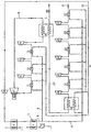
- The invention is illustrated by way of non-limiting example in the accompanying drawing, which shows a general scheme of a plant for implementing the process.
- With reference to said drawing, a liquid methane inlet line 1 leads to a pump 2. The pump 2 (indicatively of centrifugal type) feeds the liquid methane to a
heat exchanger 4, which subtracts heat from aline 5 through which nitrogen passes in counter-current. - This nitrogen originates from another
heat exchanger 6 in which awater line 7 had previously raised its temperature from about -98°C to about -34°C. - Said nitrogen is maintained at a relatively high pressure to increase the temperature difference between the methane and nitrogen in order, other conditions being equal, to achieve greater absorption of the cold provided by the liquid methane.
- The nitrogen cooled in this manner by heat transfer with liquid methane leaves the
heat exchanger 4 through a line 8, which branches into twolines specific circuits - More precisely, the
line 9 conveys the cold withdrawn from the methane to the interstage coolers (heat exchangers) 11, 12, 13 located respectively at the outlet of threestages circuit 18, which is of closed type. - At the outlet of the
interstage cooler 11 the nitrogen of the closedcircuit 18, cooled in this manner, has a pressure of about 10 bar and a temperature of about -141°C. - In this state it is expanded through a conventional
cryogenic turbine 17 by which its temperature falls to-190°C and its pressure to 1.4 bar. - The nitrogen, cooled in this manner in the closed
circuit 18, passes through aheat exchanger 19 to absorb heat from the nitrogen compressed in anopen circuit 20. - This
open circuit 20 comprises aninlet line 21, into which gaseous nitrogen is fed at a pressure of 1.15 bar absolute and a temperature of +15°C. This nitrogen undergoes successive compressions by a compressor unit composed of afirst stage 22, asecond stage 23, athird stage 24, afourth stage 25 and afifth stage 26. - The nitrogen of the
open circuit 20 undergoes the following cooling sequence: cooling implemented by anintake heat exchanger 27, cooling implemented by a plurality of interstage heat exchangers (28, 29, 30, 31) and further cooling implemented by afinal heat exchanger 32 upstream of saidheat exchanger 19 located in the final part of saidopen circuit 20. - Said
heat exchangers open circuit 20 by transferring to it the cold present in the nitrogen passing through theline 10, itself cooled by the cold subtracted from the liquid methane in theheat exchanger 4. - After collecting heat through the
respective heat exchangers lines compressor 34 which circulates it at a pressure of about 70 bar along the paths already described and in the directions indicated by the arrows. - As a result of this, the nitrogen enters the
open circuit 20 in the gaseous state through theline 21 and leaves in the liquid state through aline 3, by optimum use of the cold deriving from the vaporization of the liquid methane. - The liquid nitrogen produced in this manner can itself be used in the usual air fractionation plants to produce liquid oxygen, nitrogen and argon, and in addition for all the usual possible uses of liquid nitrogen.
- Advantageously, the process for recovering cold from liquid methane by liquid nitrogen production cycles in the aforedescribed manner results in substantial energy savings.
- With reference to the already stated real numerical values referring to a volume of 25,000 Normal cubic metres of nitrogen, the energy consumption using this process decreases to only 3,700 kWh, so drastically reducing the current energy requirement using the common liquefaction methods (for nitrogen liquefaction).
Claims (4)
- A process for the liquefaction of a cryogenic fluid by recovering the cold derived from liquid methane gasification, comprising the steps of cooling (4) with the liquid methane (1) a first cryogenic fluid (5), preferably nitrogen, and then using said first cryogenic fluid as coolant fluid in a first compressor unit (22-23-24-25-26), both for the interstage coolers (28, 29, 30, 31) and for the intake and final delivery coolers (27, 32) of said first compressor unit, the cryogenic fluid (3) being compressed by the first compressor unit (22-23-24-25-26) and liquefied in a heat exchanger (19), by characterized in that the heat exchanger is cooled another separate cryogenic fluid circulating in a closed circuit, said another separate cryogenic fluid being continuously compressed by a second compressor unit (14-15-16), expanded through a cryogenic turbine (17) to achieve a cooling temperature being lower than the liquefaction temperature of the cryogenic fluid and then fed to said heat exchanger (19), and in that the first cryogenic fluid is also used as coolant fluid in said second compressor unit (14,15,16) both for second interstage coolers (12,13) and second final delivery cooler (11) of said second compressor unit.
- A process as claimed in claim 1, wherein the another separate cryogenic fluid is nitrogen which by cooling through the expansion in the cryogenic turbine (17) is brought to a temperature of-190°C so as to obtain liquefaction of the nitrogen on reaching -180°C through said heat exchanger (19), the liquid nitrogen leaving through a controlled line (3) of the open liquefaction circuit.
- A process as claimed in claim 2, wherein the nitrogen is used in an air fractionation plant for the production of liquid oxygen, nitrogen and argon or for other possible uses of liquid nitrogen.
- An apparatus for the liquefaction of a cryogenic fluid implementing the process, of claim 1, the apparatus comprises a first closed circuit (33) with circulating first cryogenic fluid (preferably nitrogen) and said first closed circuit comprising first heat exchanger means (4), for cooling first cryogenic fluid by liquid methane;
an open circuit (20) comprising first compressor means (22-26) for compressing the cryogenic fluid and heat exchanger means (19) for liquefying the compressed cryogenic fluid (3);
the first compressor means (22-26) comprising interstage coolers (28-31), intake and final delivery coolers (27,32) for cooling the cryogenic fluid wherein said coolers being cooled by said cooled first cryogenic fluid;
characterised by
a second closed circuit (18) with circulating another separate cryogenic fluid;
the second closed circuit (18) comprising second compressor means (14-16) for compressing the another separate cryogenic fluid and expander means (17) for expanding the another separate cryogenic fluid wherein the expander means (17) being connected to the heat exchanger means (19); and
the second compressor means (14-16) comprising second interstage coolers (12,13) and second final delivery cooler (11) for cooling the another separate cryogenic fluid wherein said second interstage and second final delivery coolers being cooled by said cooled first cryogenic fluid.
Priority Applications (1)
| Application Number | Priority Date | Filing Date | Title |
|---|---|---|---|
| SI200430051T SI1469265T1 (en) | 2003-04-08 | 2004-03-24 | Process for nitrogen liquefaction by recovering the cold derived from liquid methane gasification |
Applications Claiming Priority (2)
| Application Number | Priority Date | Filing Date | Title |
|---|---|---|---|
| IT000027A ITBG20030027A1 (en) | 2003-04-08 | 2003-04-08 | RECOVERY PROCEDURE FOR REFRIGERATORS ARISING FROM THE GASIFICATION OF LIQUID METHANE. |
| ITBG20030027 | 2003-04-08 |
Publications (2)
| Publication Number | Publication Date |
|---|---|
| EP1469265A1 EP1469265A1 (en) | 2004-10-20 |
| EP1469265B1 true EP1469265B1 (en) | 2006-05-31 |
Family
ID=32894133
Family Applications (1)
| Application Number | Title | Priority Date | Filing Date |
|---|---|---|---|
| EP04007031A Expired - Lifetime EP1469265B1 (en) | 2003-04-08 | 2004-03-24 | Process for nitrogen liquefaction by recovering the cold derived from liquid methane gasification |
Country Status (7)
| Country | Link |
|---|---|
| EP (1) | EP1469265B1 (en) |
| AT (1) | ATE328258T1 (en) |
| DE (1) | DE602004001004T2 (en) |
| ES (1) | ES2264059T3 (en) |
| IT (1) | ITBG20030027A1 (en) |
| PT (1) | PT1469265E (en) |
| SI (1) | SI1469265T1 (en) |
Families Citing this family (5)
| Publication number | Priority date | Publication date | Assignee | Title |
|---|---|---|---|---|
| WO2008023000A2 (en) | 2006-08-23 | 2008-02-28 | Shell Internationale Research Maatschappij B.V. | Method and apparatus for the vaporization of a liquid hydrocarbon stream |
| DE102007005494A1 (en) * | 2007-01-30 | 2008-07-31 | Dge Dr.-Ing. Günther Engineering Gmbh | Producing liquid methane from a gas containing methane and carbon dioxide comprises scrubbing the gas to remove carbon dioxide and using the liquefied carbon dioxide to liquefy the methane |
| JP2011526993A (en) | 2007-12-21 | 2011-10-20 | シエル・インターナシヨネイル・リサーチ・マーチヤツピイ・ベー・ウイ | Method for producing a gasified hydrocarbon stream, a method for liquefying a hydrocarbon gas stream, and a circulation for cooling and reheating a nitrogen-based stream thereby liquefying and regasifying the hydrocarbon stream Method |
| CN103775239B (en) * | 2013-01-17 | 2017-01-04 | 摩尔动力(北京)技术股份有限公司 | Nearly constant temperature pressure low-temperature receiver heat engine |
| GB2512360B (en) * | 2013-03-27 | 2015-08-05 | Highview Entpr Ltd | Method and apparatus in a cryogenic liquefaction process |
Family Cites Families (9)
| Publication number | Priority date | Publication date | Assignee | Title |
|---|---|---|---|---|
| NL265913A (en) * | 1960-06-16 | |||
| GB1120712A (en) * | 1964-07-01 | 1968-07-24 | John Edward Arregger | Improvements in or relating to the separation of gas mixtures by low temperature distillation |
| US3343374A (en) * | 1964-12-16 | 1967-09-26 | Conch Int Methane Ltd | Liquid nitrogen production |
| FR2131985B1 (en) * | 1971-03-30 | 1974-06-28 | Snam Progetti | |
| DE2434238A1 (en) * | 1974-07-16 | 1976-01-29 | Linde Ag | System to store and retrieve stored energy - has gas type auxiliary energy storage medium which is liquefied when energy requirements are low |
| FR2300303A1 (en) * | 1975-02-06 | 1976-09-03 | Air Liquide | CYCLE FR |
| JPH02171580A (en) * | 1988-12-23 | 1990-07-03 | Kobe Steel Ltd | Air separating device |
| US5137558A (en) * | 1991-04-26 | 1992-08-11 | Air Products And Chemicals, Inc. | Liquefied natural gas refrigeration transfer to a cryogenics air separation unit using high presure nitrogen stream |
| JP2000337767A (en) * | 1999-05-26 | 2000-12-08 | Air Liquide Japan Ltd | Air separating method and air separating facility |
-
2003
- 2003-04-08 IT IT000027A patent/ITBG20030027A1/en unknown
-
2004
- 2004-03-24 EP EP04007031A patent/EP1469265B1/en not_active Expired - Lifetime
- 2004-03-24 DE DE602004001004T patent/DE602004001004T2/en not_active Expired - Lifetime
- 2004-03-24 ES ES04007031T patent/ES2264059T3/en not_active Expired - Lifetime
- 2004-03-24 PT PT04007031T patent/PT1469265E/en unknown
- 2004-03-24 AT AT04007031T patent/ATE328258T1/en not_active IP Right Cessation
- 2004-03-24 SI SI200430051T patent/SI1469265T1/en unknown
Also Published As
| Publication number | Publication date |
|---|---|
| DE602004001004D1 (en) | 2006-07-06 |
| SI1469265T1 (en) | 2006-10-31 |
| PT1469265E (en) | 2006-09-29 |
| ITBG20030027A1 (en) | 2004-10-09 |
| ES2264059T3 (en) | 2006-12-16 |
| DE602004001004T2 (en) | 2006-12-14 |
| ATE328258T1 (en) | 2006-06-15 |
| EP1469265A1 (en) | 2004-10-20 |
Similar Documents
| Publication | Publication Date | Title |
|---|---|---|
| RU2406949C2 (en) | Method of liquefying natural gas | |
| US4303428A (en) | Cryogenic processes for separating air | |
| CN1206505C (en) | Process for liquefying naturla gas by expansion cooling | |
| JP5226457B2 (en) | Air flow compression method and air flow compression device | |
| CN100510574C (en) | Cryogenic liquefying refrigerating method and system | |
| US4638639A (en) | Gas refrigeration method and apparatus | |
| JPH05149677A (en) | Method of liquefying nitrogen flow formed by cryogenic air separation | |
| JP2015501410A (en) | Multiple nitrogen expansion process for LNG production | |
| CN113776275A (en) | Hydrogen liquefaction method under LNG cold energy precooling | |
| US20150345834A1 (en) | Refrigeration and/or liquefaction device, and corresponding method | |
| CN103374424A (en) | Natural gas liquefaction with feed water removal | |
| CA1262434A (en) | Refrigeration method and apparatus | |
| JP2018528894A (en) | Ship with engine | |
| CA2914848C (en) | Systems and methods for natural gas liquefaction capacity augmentation | |
| EP1469265B1 (en) | Process for nitrogen liquefaction by recovering the cold derived from liquid methane gasification | |
| KR102523737B1 (en) | Expansion and storage method of liquefied natural gas stream from natural gas liquefaction plant and related plant | |
| US6170290B1 (en) | Refrigeration process and plant using a thermal cycle of a fluid having a low boiling point | |
| JP2022084066A (en) | Storage tank inner pressure holding method during liquid helium transfer, and device | |
| CN104019626A (en) | Method and device for preparing liquefied natural gas by virtue of secondary refrigeration of mixed refrigerant | |
| CN114777418B (en) | System for extracting helium from natural gas BOG by condensation method | |
| US20230251030A1 (en) | Facility and method for hydrogen refrigeration | |
| US3343374A (en) | Liquid nitrogen production | |
| RU2794011C1 (en) | Method for liquefaction of helium | |
| US10330381B2 (en) | Plant for the liquefaction of nitrogen using the recovery of cold energy deriving from the evaporation of liquefied natural gas | |
| RU2151981C1 (en) | Cryogenic system for air liquefaction |
Legal Events
| Date | Code | Title | Description |
|---|---|---|---|
| PUAI | Public reference made under article 153(3) epc to a published international application that has entered the european phase |
Free format text: ORIGINAL CODE: 0009012 |
|
| AK | Designated contracting states |
Kind code of ref document: A1 Designated state(s): AT BE BG CH CY CZ DE DK EE ES FI FR GB GR HU IE IT LI LU MC NL PL PT RO SE SI SK TR |
|
| AX | Request for extension of the european patent |
Extension state: AL LT LV MK |
|
| 17P | Request for examination filed |
Effective date: 20041111 |
|
| AKX | Designation fees paid |
Designated state(s): AT BE BG CH CY CZ DE DK EE ES FI FR GB GR HU IE IT LI LU MC NL PL PT RO SE SI SK TR |
|
| GRAP | Despatch of communication of intention to grant a patent |
Free format text: ORIGINAL CODE: EPIDOSNIGR1 |
|
| GRAC | Information related to communication of intention to grant a patent modified |
Free format text: ORIGINAL CODE: EPIDOSCIGR1 |
|
| GRAS | Grant fee paid |
Free format text: ORIGINAL CODE: EPIDOSNIGR3 |
|
| GRAA | (expected) grant |
Free format text: ORIGINAL CODE: 0009210 |
|
| AK | Designated contracting states |
Kind code of ref document: B1 Designated state(s): AT BE BG CH CY CZ DE DK EE ES FI FR GB GR HU IE IT LI LU MC NL PL PT RO SE SI SK TR |
|
| PG25 | Lapsed in a contracting state [announced via postgrant information from national office to epo] |
Ref country code: FI Free format text: LAPSE BECAUSE OF FAILURE TO SUBMIT A TRANSLATION OF THE DESCRIPTION OR TO PAY THE FEE WITHIN THE PRESCRIBED TIME-LIMIT Effective date: 20060531 Ref country code: IT Free format text: LAPSE BECAUSE OF FAILURE TO SUBMIT A TRANSLATION OF THE DESCRIPTION OR TO PAY THE FEE WITHIN THE PRESCRIBED TIME-LIMIT;WARNING: LAPSES OF ITALIAN PATENTS WITH EFFECTIVE DATE BEFORE 2007 MAY HAVE OCCURRED AT ANY TIME BEFORE 2007. THE CORRECT EFFECTIVE DATE MAY BE DIFFERENT FROM THE ONE RECORDED. Effective date: 20060531 Ref country code: AT Free format text: LAPSE BECAUSE OF FAILURE TO SUBMIT A TRANSLATION OF THE DESCRIPTION OR TO PAY THE FEE WITHIN THE PRESCRIBED TIME-LIMIT Effective date: 20060531 Ref country code: BE Free format text: LAPSE BECAUSE OF FAILURE TO SUBMIT A TRANSLATION OF THE DESCRIPTION OR TO PAY THE FEE WITHIN THE PRESCRIBED TIME-LIMIT Effective date: 20060531 Ref country code: CZ Free format text: LAPSE BECAUSE OF FAILURE TO SUBMIT A TRANSLATION OF THE DESCRIPTION OR TO PAY THE FEE WITHIN THE PRESCRIBED TIME-LIMIT Effective date: 20060531 Ref country code: CH Free format text: LAPSE BECAUSE OF FAILURE TO SUBMIT A TRANSLATION OF THE DESCRIPTION OR TO PAY THE FEE WITHIN THE PRESCRIBED TIME-LIMIT Effective date: 20060531 Ref country code: SK Free format text: LAPSE BECAUSE OF FAILURE TO SUBMIT A TRANSLATION OF THE DESCRIPTION OR TO PAY THE FEE WITHIN THE PRESCRIBED TIME-LIMIT Effective date: 20060531 Ref country code: LI Free format text: LAPSE BECAUSE OF FAILURE TO SUBMIT A TRANSLATION OF THE DESCRIPTION OR TO PAY THE FEE WITHIN THE PRESCRIBED TIME-LIMIT Effective date: 20060531 Ref country code: NL Free format text: LAPSE BECAUSE OF FAILURE TO SUBMIT A TRANSLATION OF THE DESCRIPTION OR TO PAY THE FEE WITHIN THE PRESCRIBED TIME-LIMIT Effective date: 20060531 Ref country code: PL Free format text: LAPSE BECAUSE OF FAILURE TO SUBMIT A TRANSLATION OF THE DESCRIPTION OR TO PAY THE FEE WITHIN THE PRESCRIBED TIME-LIMIT Effective date: 20060531 |
|
| REG | Reference to a national code |
Ref country code: GB Ref legal event code: FG4D Ref country code: CH Ref legal event code: EP |
|
| REG | Reference to a national code |
Ref country code: IE Ref legal event code: FG4D |
|
| REF | Corresponds to: |
Ref document number: 602004001004 Country of ref document: DE Date of ref document: 20060706 Kind code of ref document: P |
|
| REG | Reference to a national code |
Ref country code: RO Ref legal event code: EPE |
|
| PG25 | Lapsed in a contracting state [announced via postgrant information from national office to epo] |
Ref country code: SE Free format text: LAPSE BECAUSE OF FAILURE TO SUBMIT A TRANSLATION OF THE DESCRIPTION OR TO PAY THE FEE WITHIN THE PRESCRIBED TIME-LIMIT Effective date: 20060831 Ref country code: DK Free format text: LAPSE BECAUSE OF FAILURE TO SUBMIT A TRANSLATION OF THE DESCRIPTION OR TO PAY THE FEE WITHIN THE PRESCRIBED TIME-LIMIT Effective date: 20060831 |
|
| REG | Reference to a national code |
Ref country code: GR Ref legal event code: EP Ref document number: 20060402568 Country of ref document: GR |
|
| REG | Reference to a national code |
Ref country code: PT Ref legal event code: SC4A Effective date: 20060727 |
|
| NLV1 | Nl: lapsed or annulled due to failure to fulfill the requirements of art. 29p and 29m of the patents act | ||
| REG | Reference to a national code |
Ref country code: CH Ref legal event code: PL |
|
| REG | Reference to a national code |
Ref country code: ES Ref legal event code: FG2A Ref document number: 2264059 Country of ref document: ES Kind code of ref document: T3 |
|
| ET | Fr: translation filed | ||
| PLBE | No opposition filed within time limit |
Free format text: ORIGINAL CODE: 0009261 |
|
| STAA | Information on the status of an ep patent application or granted ep patent |
Free format text: STATUS: NO OPPOSITION FILED WITHIN TIME LIMIT |
|
| 26N | No opposition filed |
Effective date: 20070301 |
|
| PG25 | Lapsed in a contracting state [announced via postgrant information from national office to epo] |
Ref country code: MC Free format text: LAPSE BECAUSE OF NON-PAYMENT OF DUE FEES Effective date: 20070331 Ref country code: IE Free format text: LAPSE BECAUSE OF NON-PAYMENT OF DUE FEES Effective date: 20070326 |
|
| PG25 | Lapsed in a contracting state [announced via postgrant information from national office to epo] |
Ref country code: EE Free format text: LAPSE BECAUSE OF FAILURE TO SUBMIT A TRANSLATION OF THE DESCRIPTION OR TO PAY THE FEE WITHIN THE PRESCRIBED TIME-LIMIT Effective date: 20060531 |
|
| PG25 | Lapsed in a contracting state [announced via postgrant information from national office to epo] |
Ref country code: CY Free format text: LAPSE BECAUSE OF FAILURE TO SUBMIT A TRANSLATION OF THE DESCRIPTION OR TO PAY THE FEE WITHIN THE PRESCRIBED TIME-LIMIT Effective date: 20060531 Ref country code: LU Free format text: LAPSE BECAUSE OF NON-PAYMENT OF DUE FEES Effective date: 20070324 |
|
| PG25 | Lapsed in a contracting state [announced via postgrant information from national office to epo] |
Ref country code: HU Free format text: LAPSE BECAUSE OF FAILURE TO SUBMIT A TRANSLATION OF THE DESCRIPTION OR TO PAY THE FEE WITHIN THE PRESCRIBED TIME-LIMIT Effective date: 20061201 |
|
| REG | Reference to a national code |
Ref country code: FR Ref legal event code: PLFP Year of fee payment: 12 |
|
| REG | Reference to a national code |
Ref country code: FR Ref legal event code: PLFP Year of fee payment: 13 |
|
| REG | Reference to a national code |
Ref country code: FR Ref legal event code: PLFP Year of fee payment: 14 |
|
| REG | Reference to a national code |
Ref country code: FR Ref legal event code: PLFP Year of fee payment: 15 |
|
| PGFP | Annual fee paid to national office [announced via postgrant information from national office to epo] |
Ref country code: RO Payment date: 20180305 Year of fee payment: 15 Ref country code: GB Payment date: 20180327 Year of fee payment: 15 |
|
| PGFP | Annual fee paid to national office [announced via postgrant information from national office to epo] |
Ref country code: BG Payment date: 20180327 Year of fee payment: 15 Ref country code: PT Payment date: 20180302 Year of fee payment: 15 Ref country code: SI Payment date: 20180305 Year of fee payment: 15 Ref country code: FR Payment date: 20180326 Year of fee payment: 15 Ref country code: TR Payment date: 20180307 Year of fee payment: 15 Ref country code: GR Payment date: 20180329 Year of fee payment: 15 |
|
| PGFP | Annual fee paid to national office [announced via postgrant information from national office to epo] |
Ref country code: DE Payment date: 20180524 Year of fee payment: 15 Ref country code: ES Payment date: 20180402 Year of fee payment: 15 |
|
| REG | Reference to a national code |
Ref country code: DE Ref legal event code: R119 Ref document number: 602004001004 Country of ref document: DE |
|
| PG25 | Lapsed in a contracting state [announced via postgrant information from national office to epo] |
Ref country code: PT Free format text: LAPSE BECAUSE OF NON-PAYMENT OF DUE FEES Effective date: 20190924 Ref country code: RO Free format text: LAPSE BECAUSE OF NON-PAYMENT OF DUE FEES Effective date: 20190324 |
|
| GBPC | Gb: european patent ceased through non-payment of renewal fee |
Effective date: 20190324 |
|
| REG | Reference to a national code |
Ref country code: SI Ref legal event code: KO00 Effective date: 20191111 |
|
| PG25 | Lapsed in a contracting state [announced via postgrant information from national office to epo] |
Ref country code: DE Free format text: LAPSE BECAUSE OF NON-PAYMENT OF DUE FEES Effective date: 20191001 Ref country code: BG Free format text: LAPSE BECAUSE OF NON-PAYMENT OF DUE FEES Effective date: 20190930 Ref country code: GB Free format text: LAPSE BECAUSE OF NON-PAYMENT OF DUE FEES Effective date: 20190324 |
|
| PG25 | Lapsed in a contracting state [announced via postgrant information from national office to epo] |
Ref country code: FR Free format text: LAPSE BECAUSE OF NON-PAYMENT OF DUE FEES Effective date: 20190331 Ref country code: SI Free format text: LAPSE BECAUSE OF NON-PAYMENT OF DUE FEES Effective date: 20190325 Ref country code: GR Free format text: LAPSE BECAUSE OF NON-PAYMENT OF DUE FEES Effective date: 20191007 |
|
| REG | Reference to a national code |
Ref country code: ES Ref legal event code: FD2A Effective date: 20200728 |
|
| PG25 | Lapsed in a contracting state [announced via postgrant information from national office to epo] |
Ref country code: ES Free format text: LAPSE BECAUSE OF NON-PAYMENT OF DUE FEES Effective date: 20190325 |
|
| PG25 | Lapsed in a contracting state [announced via postgrant information from national office to epo] |
Ref country code: TR Free format text: LAPSE BECAUSE OF NON-PAYMENT OF DUE FEES Effective date: 20190324 |
|
| PGFP | Annual fee paid to national office [announced via postgrant information from national office to epo] |
Ref country code: IT Payment date: 20230222 Year of fee payment: 20 |