EP1469202A1 - Multistage pump - Google Patents
Multistage pump Download PDFInfo
- Publication number
- EP1469202A1 EP1469202A1 EP03701818A EP03701818A EP1469202A1 EP 1469202 A1 EP1469202 A1 EP 1469202A1 EP 03701818 A EP03701818 A EP 03701818A EP 03701818 A EP03701818 A EP 03701818A EP 1469202 A1 EP1469202 A1 EP 1469202A1
- Authority
- EP
- European Patent Office
- Prior art keywords
- side portion
- stage
- intermediate casing
- relief plate
- bottom portion
- Prior art date
- Legal status (The legal status is an assumption and is not a legal conclusion. Google has not performed a legal analysis and makes no representation as to the accuracy of the status listed.)
- Granted
Links
Images
Classifications
-
- F—MECHANICAL ENGINEERING; LIGHTING; HEATING; WEAPONS; BLASTING
- F04—POSITIVE - DISPLACEMENT MACHINES FOR LIQUIDS; PUMPS FOR LIQUIDS OR ELASTIC FLUIDS
- F04D—NON-POSITIVE-DISPLACEMENT PUMPS
- F04D29/00—Details, component parts, or accessories
- F04D29/08—Sealings
- F04D29/086—Sealings especially adapted for liquid pumps
-
- F—MECHANICAL ENGINEERING; LIGHTING; HEATING; WEAPONS; BLASTING
- F04—POSITIVE - DISPLACEMENT MACHINES FOR LIQUIDS; PUMPS FOR LIQUIDS OR ELASTIC FLUIDS
- F04D—NON-POSITIVE-DISPLACEMENT PUMPS
- F04D1/00—Radial-flow pumps, e.g. centrifugal pumps; Helico-centrifugal pumps
- F04D1/06—Multi-stage pumps
- F04D1/063—Multi-stage pumps of the vertically split casing type
-
- F—MECHANICAL ENGINEERING; LIGHTING; HEATING; WEAPONS; BLASTING
- F04—POSITIVE - DISPLACEMENT MACHINES FOR LIQUIDS; PUMPS FOR LIQUIDS OR ELASTIC FLUIDS
- F04D—NON-POSITIVE-DISPLACEMENT PUMPS
- F04D1/00—Radial-flow pumps, e.g. centrifugal pumps; Helico-centrifugal pumps
- F04D1/06—Multi-stage pumps
- F04D1/063—Multi-stage pumps of the vertically split casing type
- F04D1/066—Multi-stage pumps of the vertically split casing type the casing consisting of a plurality of annuli bolted together
-
- F—MECHANICAL ENGINEERING; LIGHTING; HEATING; WEAPONS; BLASTING
- F04—POSITIVE - DISPLACEMENT MACHINES FOR LIQUIDS; PUMPS FOR LIQUIDS OR ELASTIC FLUIDS
- F04D—NON-POSITIVE-DISPLACEMENT PUMPS
- F04D29/00—Details, component parts, or accessories
- F04D29/40—Casings; Connections of working fluid
- F04D29/42—Casings; Connections of working fluid for radial or helico-centrifugal pumps
- F04D29/426—Casings; Connections of working fluid for radial or helico-centrifugal pumps especially adapted for liquid pumps
- F04D29/4266—Casings; Connections of working fluid for radial or helico-centrifugal pumps especially adapted for liquid pumps made of sheet metal
Definitions
- the present invention relates to a multistage pump, and more particularly to a multistage pump having a plurality of intermediate casings formed by press-forming a steel plate.
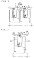
- FIG. 7 is a vertical cross-sectional view showing a structure including intermediate casings in a conventional multistage pump. As shown in FIG. 7, impellers 101 are housed in the intermediate casings 100.
- the intermediate casing 100 has a cylindrical side portion 102, a fitting portion 103 formed substantially into a sigmoid shape, and a bottom portion 104 extending radially inward from the fitting portion 103.
- An axial end face 102a and an inner surface 102b of a cylindrical side portion 102 of an adjacent intermediate casing are held in contact with the fitting portion 103.
- the inner surface 120b of the cylindrical side portion 102 of the adjacent intermediate casing and the fitting portion 103 having substantially a sigmoid shape form a recess in which an O-ring 110 is fitted.
- the fitting portion 103 of the intermediate casing is formed by buckling a steel plate through press forming.
- the fitting portion 103 of the intermediate casing is formed by press forming
- the shape of the recess for the O-ring is unlikely to be fixed due to variations of the hardness or the thickness of a casing material, and thus it is difficult to obtain a stable shape of the fitting portion.
- a die for press forming is required to have high accuracy.
- a special O-ring 110 that is fitted into the shape of the fitting portion 103 is required, cost rises problematically.
- the present invention has been made in view of the above drawbacks of the prior art. It is, therefore, an object of the present invention to provide a multistage pump which can maintain stable sealing capability and stable accuracy in an intermediate casing and can employ a general-purpose O-ring which is inexpensive.
- a multistage pump having a plurality of intermediate casings formed by press-forming a steel plate, characterized in that each of the intermediate casings has a cylindrical side portion, a stage flat portion with which an axial end face of an adjacent intermediate casing is held in contact, a stage side portion extending axially from the stage flat portion, and a bottom portion extending radially inward from the stage side portion, wherein a relief plate having an outer circumferential end face which is held in contact with an inner surface of a cylindrical side portion of the adjacent intermediate casing is attached to the bottom portion of the intermediate casing, wherein the relief plate, the stage side portion, the stage flat portion, and the inner surface of the cylindrical side portion of the adjacent intermediate casing form a space in which an O-ring is fitted.
- a multistage pump having a plurality of intermediate casings formed by press-forming a steel plate, characterized in that each of the intermediate casings has a cylindrical side portion, a stage flat portion with which an axial end face of an adjacent intermediate casing is held in contact, a stage side portion extending axially from the stage flat portion, and a bottom portion extending radially inward from the stage side portion, wherein a relief plate having an outer circumferential end face which is held in contact with an inner surface of a cylindrical side portion of the adjacent intermediate casing is attached to the bottom portion of the intermediate casing, wherein the relief plate, the stage side portion, the stage flat portion, and the inner surface of the cylindrical side portion of the adjacent intermediate casing form a space in which an O-ring is fitted, wherein a return vane interposed between a side plate and the relief plate is formed integrally with the relief plate.
- a multistage pump can have a simple structure which can be manufactured simply by press forming. Accordingly, it is possible to readily form a recess for an O-ring disposed between intermediate casings with high accuracy. Thus, it is possible to maintain stable sealing capability and stable accuracy.
- Such a recess for an O-ring can be changed in shape such that a commercially available O-ring is fitted in the recess. Thus, since any commercially available O-ring can be used, cost can be reduced.
- the multistage pump is characterized in that a height of the return vane at an outer circumferential side is larger than that at an inner circumferential side.
- a passage cross-section is widened at an inlet side of the return vane to lower a flow velocity and to reduce a loss which would be caused by a step corresponding to the thickness of the relief plate.
- the multistage pump is characterized in that the relief plate is attached to the bottom portion at a position near its outermost portion so as to form a gap between a radially inner portion of the relief plate and the bottom portion of the intermediate casing according to an amount of deformation of the bottom portion due to a differential pressure between stages.
- a differential pressure between stages which is produced by a pressure of the fluid pressurized by an impeller, is applied to an inner surface of the bottom portion so as to expand the bottom portion toward the low pressure side.
- the relief plate since a gap is preformed between the bottom portion and the relief plate, the amount of deformation due to the differential pressure between the stages is cancelled by the gap. Accordingly, the relief plate is not subjected to the influence of the deformation of the bottom portion and is not broken.
- FIGS. 1 through 6 A multistage pump according to embodiments of the present invention will be described below in detail with reference to FIGS. 1 through 6.
- like or corresponding parts are denoted by the same reference numerals, and will not be described below repetitively.
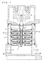
- FIG. 1 is a vertical cross-sectional view showing a multistage pump according to a first embodiment of the present invention.
- a multistage pump according to the present embodiment a plurality of intermediate casings 2 is housed in an outer casing 1, and impellers 4 attached to a main shaft 3 are housed in the respective intermediate casings 2.
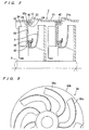
- FIG. 2 is a partial enlarged view showing a structure including the intermediate casings shown in FIG. 1.
- each of the intermediate casings 2 in the present embodiment is formed substantially into a cylindrical receptacle.
- the intermediate casing 2 includes a cylindrical side portion 21, a protruding portion 22 protruding radially outward from the cylindrical side portion 21, a stage flat portion 23 extending radially inward from the protruding portion 22, a stage side portion 24 extending axially from the stage flat portion 23, and a bottom portion 25 extending radially inward from the stage side portion 24.
- the intermediate casing 2 is produced by press-forming a steel plate.
- the protruding portion 22 has an outside diameter larger than the outside diameter of the cylindrical side portion 21.
- the stage side portion 24 has an outside diameter slightly smaller than the inside diameter of the cylindrical side portion 21.
- the stage flat portion 23 is arranged so as to be perpendicular to the cylindrical side portion 21.
- the cylindrical side portion 21 has an axial end face 21a which is held in contact with a stage flat portion 23 of an adjacent intermediate casing 2 substantially over the entire surface of the axial end face 21a. As long as the end face of the cylindrical side portion 21 can maintain a contacting area with the adjacent stage flat portion 23, the stage flat portion 23 may be inclined at a predetermined angle with respect to the cylindrical side portion 21 rather than perpendicular to the cylindrical side portion 21.
- a relief plate 30 is attached to the bottom portion 25 of the intermediate casing 2 by welding.
- Return vanes 34 are interposed between the relief plate 30 and a side plate 32 and welded to the relief plate 30 and the side plate 32.
- An outer circumferential end face 30a of the relief plate 30 is held in contact with an inner circumferential surface of a cylindrical side portion 21 of an adjacent intermediate casing 2.
- the relief plate 30, the stage side portion 24, the stage flat portion 23, and the inner surface of the cylindrical side portion 21 of the adjacent intermediate casing 2 form a space in which an O-ring 40 is fitted.
- the intermediate casing 2 has a simple structure which can be manufactured simply by press forming.
- a liner ring 42 is attached to an inner edge portion 26 of the bottom portion 25 of the intermediate casing 2, and a small gap is formed between the liner ring 42 and a suction portion of the impeller 4.
- the liner ring 42 prevents water having a high pressure from leaking into the suction portion.
- a pumping liquid drawn from a suction port 5a (see FIG. 1) is pressurized by the impellers 4 rotated by the main shaft 3.
- the pressurized pumping liquid is introduced into a suction portion of a subsequent impeller 4 through a passage formed by the return vanes 34 interposed between the relief plate 30 and the side plate 32.
- the pumping liquid is pressurized by each stage of the impellers 4, recovered in pressure while flowing through a passage formed by each stage of the return vanes 34, and finally discharged from a discharge port 5b (see FIG. 1) of to the exterior of the pump.
- FIG. 3 is a plan view showing a portion of a relief plate 36 in a case where a relief plate and return vanes are formed integrally with each other.
- a disk-like steel plate is folded into return vanes 36a so as to form the return vanes 36a and the relief plate body 36b integrally with each other.
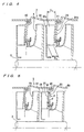
- FIG. 4 is a vertical cross-sectional view showing a structure including intermediate casings according to a second embodiment of the present invention.
- steps corresponding to the thickness of the relief plate body 36b are formed at base portions of the return vanes 36a.
- the steps enlarge the passages abruptly to cause a loss.
- the height h1 of the return vanes 36a at inlet sides i.e., the height of the return vanes 36a at outer circumferential sides is larger than the height h2 of the return vanes 36a at outlet sides.
- passage cross sections are widened at the inlet sides to lower the flow velocity and to reduce the loss.
- FIG. 5 is a vertical cross-sectional view showing a structure including intermediate casings according to a third embodiment of the present invention.
- a pumping liquid pressurized by the impeller 4a is introduced through a passage formed by the return vanes 34 into a subsequent impeller 4b. Further, a fluid pressure of the pressurized fluid is applied to a back side of the bottom portion 25.
- a difference between a fluid pressure in the return vanes 34 and a fluid pressure on the back side of the bottom portion 25 (differential pressure between stages) is applied in a direction indicated by an arrow P in FIG. 5.
- the bottom portion 25 is deformed on a low pressure side from a radially outward portion to a radially inward portion. If the amount of deformation is large, then an excessive stress is produced at welding portions of the bottom portion 25 with the return vanes 34 so as to cause breakage of the bottom portion 25.
- the relief plate 30 and the bottom portion 25 are welded at a portion W near the outermost portion so as to form a gap between a radially inner portion of the relief plate 30 and the bottom portion 25.
- the size d of the gap is set so as not to deform the relief plate 30 provided adjacent to the bottom portion 25 even if the bottom portion 25 is deformed due to a pressure produced by the impeller 4b.
- the size d of the gap is set such that the bottom portion 25 is brought into light contact with the relief plate 30 or otherwise is not brought into contact with the relief plate 30 even if the bottom portion 25 is deformed.
- a differential pressure between the stages which is produced by a pressure of the fluid pressurized by the impeller 4b, is applied to an inner surface of the bottom portion 25 so as to expand the bottom portion 25 toward the low pressure side.
- a gap d is preformed between the bottom portion 25 and the relief plate 30, the amount of deformation due to the differential pressure between the stages is cancelled by the gap d.
- the relief plate 30 attached to the bottom portion 25 by welding at the portion W near the outermost portion is not subjected to the influence of the deformation of the bottom portion 25 and is not broken.
- a relief plate 36 having return vanes 36a and a relief plate body 36b formed integrally with each other as shown in FIG. 3 may be attached to the relief plate 30 attached to the bottom portion 25.
- a multistage pump can have a simple structure which can be manufactured simply by press forming. Accordingly, it is possible to readily form a recess for an O-ring disposed between intermediate casings with high accuracy. Thus, it is possible to maintain stable sealing capability and stable accuracy.
- Such a recess for an O-ring can be changed in shape such that a commercially available O-ring is fitted in the recess. Thus, since any commercially available O-ring can be used, cost can be reduced.
- the present invention can suitably be used for a multistage pump having a plurality of intermediate casings formed by press-forming a steel plate.
Landscapes
- Engineering & Computer Science (AREA)
- Mechanical Engineering (AREA)
- General Engineering & Computer Science (AREA)
- Structures Of Non-Positive Displacement Pumps (AREA)
Abstract
Description
Claims (4)
- A multistage pump having a plurality of intermediate casings formed by press-forming a steel plate, characterized in that:wherein a relief plate having an outer circumferential end face which is held in contact with an inner surface of a cylindrical side portion of said adjacent intermediate casing is attached to said bottom portion of said intermediate casing,each of said intermediate casings has a cylindrical side portion, a stage flat portion with which an axial end face of an adjacent intermediate casing is held in contact, a stage side portion extending axially from said stage flat portion, and a bottom portion extending radially inward from said stage side portion,
wherein said relief plate, said stage side portion, said stage flat portion, and said inner surface of said cylindrical side portion of said adjacent intermediate casing form a space in which an O-ring is fitted. - A multistage pump having a plurality of intermediate casings formed by press-forming a steel plate, characterized in that:wherein a relief plate having an outer circumferential end face which is held in contact with an inner surface of a cylindrical side portion of said adjacent intermediate casing is attached to said.. bottom portion of said intermediate casing,each of said intermediate casings has a cylindrical side portion, a stage flat portion with which an axial end face of an adjacent intermediate casing is held in contact, a stage side portion extending axially from said stage flat portion, and a bottom portion extending radially inward from said stage side portion,
wherein said relief plate, said stage side portion, said stage flat portion, and said inner surface of said cylindrical side portion of said adjacent intermediate casing form a space in which an O-ring is fitted,
wherein a return vane interposed between a side plate and said relief plate is formed integrally with said relief plate. - The multistage pump as recited in claim 2, characterized in that a height of said return vane at an outer circumferential side is larger than that at an inner circumferential side.
- The multistage pump as recited in any one of claims 1 through 3, characterized in that said relief plate is attached to said bottom portion at a position near its outermost portion so as to form a gap between a radially inner portion of said relief plate and said bottom portion of said intermediate casing according to an amount of deformation of said bottom portion due to a differential pressure between stages.
Applications Claiming Priority (3)
| Application Number | Priority Date | Filing Date | Title |
|---|---|---|---|
| JP2002012185 | 2002-01-21 | ||
| JP2002012185A JP3986317B2 (en) | 2002-01-21 | 2002-01-21 | Multistage pump |
| PCT/JP2003/000462 WO2003062645A1 (en) | 2002-01-21 | 2003-01-21 | Multistage pump |
Publications (3)
| Publication Number | Publication Date |
|---|---|
| EP1469202A1 true EP1469202A1 (en) | 2004-10-20 |
| EP1469202A4 EP1469202A4 (en) | 2009-06-24 |
| EP1469202B1 EP1469202B1 (en) | 2012-03-14 |
Family
ID=27606036
Family Applications (1)
| Application Number | Title | Priority Date | Filing Date |
|---|---|---|---|
| EP03701818A Expired - Lifetime EP1469202B1 (en) | 2002-01-21 | 2003-01-21 | Multistage pump |
Country Status (5)
| Country | Link |
|---|---|
| US (1) | US7648337B2 (en) |
| EP (1) | EP1469202B1 (en) |
| JP (1) | JP3986317B2 (en) |
| CN (1) | CN1620556A (en) |
| WO (1) | WO2003062645A1 (en) |
Cited By (2)
| Publication number | Priority date | Publication date | Assignee | Title |
|---|---|---|---|---|
| WO2014206637A1 (en) * | 2013-06-24 | 2014-12-31 | Grundfos Holding A/S | Centrifugal pump |
| WO2014206638A1 (en) * | 2013-06-24 | 2014-12-31 | Grundfos Holding A/S | Centrifugal pump |
Families Citing this family (13)
| Publication number | Priority date | Publication date | Assignee | Title |
|---|---|---|---|---|
| JP4593962B2 (en) * | 2004-04-26 | 2010-12-08 | 株式会社荏原製作所 | Centrifugal pump and method of manufacturing centrifugal pump |
| JP4633396B2 (en) * | 2004-07-16 | 2011-02-16 | 株式会社荏原製作所 | Centrifugal pump |
| US20090246039A1 (en) * | 2006-01-09 | 2009-10-01 | Grundfos Pumps Corporation | Carrier assembly for a pump |
| US8172523B2 (en) * | 2006-10-10 | 2012-05-08 | Grudfos Pumps Corporation | Multistage pump assembly having removable cartridge |
| US7946810B2 (en) * | 2006-10-10 | 2011-05-24 | Grundfos Pumps Corporation | Multistage pump assembly |
| JP2007205360A (en) * | 2007-05-15 | 2007-08-16 | Ebara Corp | Centrifugal pump |
| EP2112380A1 (en) * | 2008-04-21 | 2009-10-28 | DP Industries B.V. | Multi-stage centrifugal pump of the in line-type |
| US20100284831A1 (en) * | 2009-05-06 | 2010-11-11 | Grundfos Pumps Corporation | Adaptors for multistage pump assemblies |
| US9334876B2 (en) | 2011-04-12 | 2016-05-10 | Thermo Neslab Inc. | Pump casing and related apparatus and methods |
| US10233937B1 (en) * | 2015-02-24 | 2019-03-19 | Franklin Electric Co., Inc. | Submersible pump thrust surface arrangement |
| EP3176441B1 (en) * | 2015-12-02 | 2021-09-15 | Grundfos Holding A/S | Multistage pump |
| CN116576148B (en) * | 2023-03-30 | 2026-03-10 | 利欧集团浙江泵业有限公司 | Pump body structure that leakproofness is high |
| CN116576154B (en) * | 2023-03-30 | 2026-02-10 | 利欧集团浙江泵业有限公司 | A combined structure for a household water pump |
Family Cites Families (11)
| Publication number | Priority date | Publication date | Assignee | Title |
|---|---|---|---|---|
| JPS4994207U (en) * | 1972-12-07 | 1974-08-14 | ||
| JPS5338042B2 (en) | 1973-01-10 | 1978-10-13 | ||
| JPS5265065A (en) | 1975-11-26 | 1977-05-30 | Shikoku Seisakusho Kk | Straw cutter |
| JPS5265065U (en) * | 1976-09-14 | 1977-05-13 | ||
| AT369515B (en) | 1979-06-12 | 1983-01-10 | Garvenswerke Pumpen Motoren Un | PUMP AND METHOD FOR INSTALLING A SEAL IN A PUMP |
| IT8030902U1 (en) | 1980-12-29 | 1982-06-29 | Lowara Spa | MULTISTAGE PUMP STAGE CONTAINER |
| DE3816280C2 (en) | 1988-05-12 | 1997-03-20 | Klein Schanzlin & Becker Ag | Housing part for centrifugal pumps |
| US5256033A (en) * | 1990-11-25 | 1993-10-26 | Ebara Corporation | Sheet metal interstage casing for a pump |
| US5318403A (en) * | 1990-12-25 | 1994-06-07 | Ebara Corporation | Interstage casing for a pump made of sheet metal and method of manufacturing the same |
| JP3878689B2 (en) | 1996-05-17 | 2007-02-07 | 三相電機株式会社 | Multistage pump casing and manufacturing method thereof |
| JP3352924B2 (en) * | 1997-09-30 | 2002-12-03 | 株式会社荏原製作所 | Fluid machinery |
-
2002
- 2002-01-21 JP JP2002012185A patent/JP3986317B2/en not_active Expired - Lifetime
-
2003
- 2003-01-21 US US10/501,885 patent/US7648337B2/en not_active Expired - Lifetime
- 2003-01-21 EP EP03701818A patent/EP1469202B1/en not_active Expired - Lifetime
- 2003-01-21 WO PCT/JP2003/000462 patent/WO2003062645A1/en not_active Ceased
- 2003-01-21 CN CNA038025388A patent/CN1620556A/en active Pending
Cited By (7)
| Publication number | Priority date | Publication date | Assignee | Title |
|---|---|---|---|---|
| WO2014206637A1 (en) * | 2013-06-24 | 2014-12-31 | Grundfos Holding A/S | Centrifugal pump |
| WO2014206638A1 (en) * | 2013-06-24 | 2014-12-31 | Grundfos Holding A/S | Centrifugal pump |
| EP2818722A1 (en) * | 2013-06-24 | 2014-12-31 | Grundfos Holding A/S | Centrifugal pump |
| EP2818721A1 (en) * | 2013-06-24 | 2014-12-31 | Grundfos Holding A/S | Centrifugal pump |
| CN105339667A (en) * | 2013-06-24 | 2016-02-17 | 格兰富控股联合股份公司 | Centrifugal pump |
| US10082155B2 (en) | 2013-06-24 | 2018-09-25 | Grundfos Holding A/S | Centrifugal pump |
| US10502214B2 (en) | 2013-06-24 | 2019-12-10 | Grundfos Holding A/S | Centrifugal pump |
Also Published As
| Publication number | Publication date |
|---|---|
| JP3986317B2 (en) | 2007-10-03 |
| CN1620556A (en) | 2005-05-25 |
| EP1469202B1 (en) | 2012-03-14 |
| EP1469202A4 (en) | 2009-06-24 |
| WO2003062645A1 (en) | 2003-07-31 |
| JP2003214383A (en) | 2003-07-30 |
| US20050147505A1 (en) | 2005-07-07 |
| US7648337B2 (en) | 2010-01-19 |
Similar Documents
| Publication | Publication Date | Title |
|---|---|---|
| US7648337B2 (en) | Multistage pump | |
| US5310310A (en) | Pump casing made of sheet metal | |
| EP0492604B1 (en) | Interstage casing for a pump made of sheet metal | |
| KR970010514B1 (en) | Sheet metal centrifugal pump casing | |
| US5318403A (en) | Interstage casing for a pump made of sheet metal and method of manufacturing the same | |
| CN1989347A (en) | Centrifugal pump | |
| US5184937A (en) | Centrifugal pump casing | |
| US7632065B2 (en) | Centrifugal pump and method of manufacturing the same | |
| EP0492606B1 (en) | Interstage casing for a pump made of sheet metal | |
| US7247001B2 (en) | Impeller | |
| US6267555B1 (en) | Sheet metal casing for multistage pump and method for manufacturing the same | |
| US5235744A (en) | Method of manufacturing a centrifugal pump casing | |
| EP0442070A1 (en) | Sheet metal pump casing | |
| EP1020644B1 (en) | A fluid machinery, a flange for fluid machinery, and a method for manufacturing them | |
| HK1077612A (en) | Multistage pump | |
| JPH0524999U (en) | Steel plate intermediate casing for pump | |
| JPH09228976A (en) | Multistage pump | |
| JP3004467B2 (en) | Sheet metal pump casing | |
| JPS647238B2 (en) | ||
| JPH0361699A (en) | Volute pump casing | |
| JPH0361698A (en) | Volute pump made of sheet metal |
Legal Events
| Date | Code | Title | Description |
|---|---|---|---|
| PUAI | Public reference made under article 153(3) epc to a published international application that has entered the european phase |
Free format text: ORIGINAL CODE: 0009012 |
|
| 17P | Request for examination filed |
Effective date: 20040726 |
|
| AK | Designated contracting states |
Kind code of ref document: A1 Designated state(s): AT BE BG CH CY CZ DE DK EE ES FI FR GB GR HU IE IT LI LU MC NL PT SE SI SK TR |
|
| A4 | Supplementary search report drawn up and despatched |
Effective date: 20090526 |
|
| 17Q | First examination report despatched |
Effective date: 20091015 |
|
| RIC1 | Information provided on ipc code assigned before grant |
Ipc: F04D 29/08 20060101AFI20110721BHEP Ipc: F04D 29/42 20060101ALI20110721BHEP |
|
| GRAP | Despatch of communication of intention to grant a patent |
Free format text: ORIGINAL CODE: EPIDOSNIGR1 |
|
| GRAS | Grant fee paid |
Free format text: ORIGINAL CODE: EPIDOSNIGR3 |
|
| GRAA | (expected) grant |
Free format text: ORIGINAL CODE: 0009210 |
|
| AK | Designated contracting states |
Kind code of ref document: B1 Designated state(s): DE DK IT |
|
| REG | Reference to a national code |
Ref country code: DE Ref legal event code: R096 Ref document number: 60340262 Country of ref document: DE Effective date: 20120510 |
|
| PLBE | No opposition filed within time limit |
Free format text: ORIGINAL CODE: 0009261 |
|
| STAA | Information on the status of an ep patent application or granted ep patent |
Free format text: STATUS: NO OPPOSITION FILED WITHIN TIME LIMIT |
|
| PG25 | Lapsed in a contracting state [announced via postgrant information from national office to epo] |
Ref country code: DK Free format text: LAPSE BECAUSE OF FAILURE TO SUBMIT A TRANSLATION OF THE DESCRIPTION OR TO PAY THE FEE WITHIN THE PRESCRIBED TIME-LIMIT Effective date: 20120314 |
|
| 26N | No opposition filed |
Effective date: 20121217 |
|
| REG | Reference to a national code |
Ref country code: DE Ref legal event code: R097 Ref document number: 60340262 Country of ref document: DE Effective date: 20121217 |
|
| PGFP | Annual fee paid to national office [announced via postgrant information from national office to epo] |
Ref country code: DE Payment date: 20211130 Year of fee payment: 20 |
|
| PGFP | Annual fee paid to national office [announced via postgrant information from national office to epo] |
Ref country code: IT Payment date: 20211213 Year of fee payment: 20 |
|
| REG | Reference to a national code |
Ref country code: DE Ref legal event code: R071 Ref document number: 60340262 Country of ref document: DE |