EP1469133A2 - Apparatus and system for through flow of a fluid - Google Patents
Apparatus and system for through flow of a fluid Download PDFInfo
- Publication number
- EP1469133A2 EP1469133A2 EP04252163A EP04252163A EP1469133A2 EP 1469133 A2 EP1469133 A2 EP 1469133A2 EP 04252163 A EP04252163 A EP 04252163A EP 04252163 A EP04252163 A EP 04252163A EP 1469133 A2 EP1469133 A2 EP 1469133A2
- Authority
- EP
- European Patent Office
- Prior art keywords
- closure
- base unit
- members
- base
- fluid
- Prior art date
- Legal status (The legal status is an assumption and is not a legal conclusion. Google has not performed a legal analysis and makes no representation as to the accuracy of the status listed.)
- Granted
Links
- 239000012530 fluid Substances 0.000 title claims abstract description 17
- 230000000630 rising effect Effects 0.000 claims abstract description 6
- XLYOFNOQVPJJNP-UHFFFAOYSA-N water Substances O XLYOFNOQVPJJNP-UHFFFAOYSA-N 0.000 claims description 10
- 239000005060 rubber Substances 0.000 claims description 6
- 238000001035 drying Methods 0.000 claims description 5
- 238000000465 moulding Methods 0.000 claims description 5
- 239000004567 concrete Substances 0.000 claims description 4
- 239000000463 material Substances 0.000 claims description 4
- 239000004033 plastic Substances 0.000 claims description 4
- 230000000295 complement effect Effects 0.000 claims description 3
- 230000008595 infiltration Effects 0.000 claims description 3
- 238000001764 infiltration Methods 0.000 claims description 3
- 230000002441 reversible effect Effects 0.000 claims description 2
- 230000009182 swimming Effects 0.000 claims description 2
- 238000010276 construction Methods 0.000 description 4
- 230000000694 effects Effects 0.000 description 2
- 238000000034 method Methods 0.000 description 2
- 239000011800 void material Substances 0.000 description 2
- 238000009412 basement excavation Methods 0.000 description 1
- 239000011449 brick Substances 0.000 description 1
- 239000000706 filtrate Substances 0.000 description 1
- 239000004746 geotextile Substances 0.000 description 1
- 238000010438 heat treatment Methods 0.000 description 1
- 238000001746 injection moulding Methods 0.000 description 1
- 238000012423 maintenance Methods 0.000 description 1
- 238000012986 modification Methods 0.000 description 1
- 230000004048 modification Effects 0.000 description 1
Images


Classifications
-
- E—FIXED CONSTRUCTIONS
- E03—WATER SUPPLY; SEWERAGE
- E03F—SEWERS; CESSPOOLS
- E03F1/00—Methods, systems, or installations for draining-off sewage or storm water
- E03F1/002—Methods, systems, or installations for draining-off sewage or storm water with disposal into the ground, e.g. via dry wells
- E03F1/005—Methods, systems, or installations for draining-off sewage or storm water with disposal into the ground, e.g. via dry wells via box-shaped elements
Definitions
- the invention relates to apparatus for providing through flow of a fluid, and to a system utilising such apparatus.
- Modem building techniques are such that earth or the ground is either compacted so that run-off of surplus water is not possible, or the earth or ground is in any event rendered impermeable by the use of concrete, metalled surfaces such as road-ways, and the like.
- apparatus for providing through flow of a fluid comprising a base unit which is adapted to receive a fluid, having a base, and boundary walls rising therefrom, to define an open top, and a substantially planar closure for the open top, which closure is adapted for passage of fluid therethrough, there being respective means of the base unit and closure for interengagement of the base unit and closure whereby when the interengagement means are interengaged, a closed unit is obtained.
- the closure may comprise a grid which supports the respective interengagement means of the closure. This provides for ease of construction for example by moulding, particularly the said means may comprise a plurality of spaced members depending from the grid and laid out in a desired array.
- the respective interengagement means of the base unit may comprise spaced upright members rising from the base and may be laid out in an array corresponding with the desired array of the closure. This provides for ease of assembly of a base unit and closure.
- the members of the closure may be female members and the members of the base unit may be male members. This provides for positive interconnection.
- the closure may be reversible so that the members can define spaces, and there may be a plurality of inserts which can be inserted into the spaces to provide a generally planar surface.
- This provides a particularly suitable closed unit used as a paving construction.
- Each insert may have a part complementary in shape to a part of a respective member of the closure, and substantially the same height thereas whereby to form a substantially planar surface. This again provides for a suitable paving construction.
- the female members may be tubular to provide fluid access to/from the base unit. Thus the female members provide drainage into the base unit with the apparatus is used to collect water.
- Each insert may be selected from a group of materials which may comprise plastic, rubber, reclaimed rubber and concrete. This provides for relative ease of construction, for example by moulding. Moreover, a surface of an insert remote from the interior of the apparatus may be moulded with a desired surface pattern or finish. This can provide for an aesthetic and/or functional aspect such as grip.
- the apparatus may comprise a storm water infiltration module, which module may comprise part of a paving system round a dwelling, swimming pool or under a path, road, drive, parking space, loading bay, filling station apron or the like.
- the apparatus may comprise a crop-drying floor, suitably the crop being grain.
- Respective closure units of adjacent base units may be offset or overlapped whereby to tie the system together.
- apparatus 1, 10 providing through flow of fluid, comprising a base unit 2 to receive a fluid, having a base 3 and boundary walls 4 rising therefrom to define an open top 5, opposite the base 3 and a substantially planar closure 6 for the open top 5, which closure 6 is adapted for passage of fluid therethrough, there being respective means 7, 8 of the base unit 2 and closure 6 for interengagement of the base unit and closure whereby when the interengagement means 7, 8 are interengaged, a closed unit 9 is obtained.
- reference to a 'closed' unit refers to the assembly of base unit 2 and closure 6, the base, boundary walls 4 and closure 6 being, in the embodiments, perforated, or having through passages defined therein for passage therethrough of water when the apparatus 9 comprises a module of a storm water infiltration system or of heated air when the apparatus is a module of a crop drying floor.
- both the base unit 2 and closure 6 are formed as by moulding, for example injection moulding of plastic to provide a rigid structure.
- the interengagement means 7 of the base unit 2 comprise an array of integral formed male members, suitably tubular columns, the disposition of the array being similar to that of the interengagement means 8 of the closure 6, which are integrally formed female members or tubes depending from a grid forming a body of the closure 6.
- the closure 6 can be reversed so that the female interconnection means 8 are upstanding from the grid, the male columns 7 on assembly entering the bases thereof.
- the female tubes 8 then define spaces 11 in which inserts 12 can be inserted, there being complementary parts 13 of the inserts 12 which mate with a part of the external surface of an adjacent tube 8 to form a complete paved surface provided by the inserts, which may be formed of any suitable material such as rubber, reclaimed rubber, plastic, brick, concrete or the like.
- the upper, in use, surface of the inserts 12 may have a suitable surface configuration 14 or finish to provide an aesthetic and/or functional, e.g. gripping, effect.
- the inserts 12 can be replaced singly, when damaged, and moreover form essentially a false floor in combination with a module formed from an assembled base unit and closure.
- Fig. 4 shows a system built up from a series of modules, which are tied together by offset or overlapping closures 6.
- a relatively shallow apparatus in Fig. 1 the base unit could be 200mm deep and the closure 50mm which can be placed in a suitable excavation so that the upper in use surface of the closure 6, or inserts 12, is flush with surrounding ground or structures for example providing a walkway around a dwelling drainage.
- a void may be left open or filled with say gravel.
- the columns 7 of the base unit 3 could be separate items which could be screwed into position on the base.
- the base units 3 can be stacked, and, in Fig. 4, the closure 6 or inserts 12 could be of varied structures to provide for varied desired surface finishes.
- a module 1, 10, 6/12 can be encased in a geotextile material, which may be water permeable or impermeable. It is also to be understood that apparatus described herein with reference to the drawings may comprise:-
Landscapes
- Health & Medical Sciences (AREA)
- Life Sciences & Earth Sciences (AREA)
- Engineering & Computer Science (AREA)
- Hydrology & Water Resources (AREA)
- Public Health (AREA)
- Water Supply & Treatment (AREA)
- Road Paving Structures (AREA)
- Feeding And Controlling Fuel (AREA)
Abstract
Description
- The invention relates to apparatus for providing through flow of a fluid, and to a system utilising such apparatus.
- Modem building techniques are such that earth or the ground is either compacted so that run-off of surplus water is not possible, or the earth or ground is in any event rendered impermeable by the use of concrete, metalled surfaces such as road-ways, and the like.
- Rainwater, or melt water, cannot then drain off, causing flooding, particularly in a flash storm situation. Moreover, water which can be contaminated with say oil or petrol spillage at a refuelling location such as a garage in parking lots or loading bays, cannot readily be handled.
- It is accordingly an object of the invention to seek to mitigate these disadvantages.
- According to a first aspect of the invention there is provided apparatus for providing through flow of a fluid, comprising a base unit which is adapted to receive a fluid, having a base, and boundary walls rising therefrom, to define an open top, and a substantially planar closure for the open top, which closure is adapted for passage of fluid therethrough, there being respective means of the base unit and closure for interengagement of the base unit and closure whereby when the interengagement means are interengaged, a closed unit is obtained.
- The closure may comprise a grid which supports the respective interengagement means of the closure. This provides for ease of construction for example by moulding, particularly the said means may comprise a plurality of spaced members depending from the grid and laid out in a desired array.
- The respective interengagement means of the base unit may comprise spaced upright members rising from the base and may be laid out in an array corresponding with the desired array of the closure. This provides for ease of assembly of a base unit and closure.
- The members of the closure may be female members and the members of the base unit may be male members. This provides for positive interconnection.
- The closure may be reversible so that the members can define spaces, and there may be a plurality of inserts which can be inserted into the spaces to provide a generally planar surface.
- This provides a particularly suitable closed unit used as a paving construction.
- Each insert may have a part complementary in shape to a part of a respective member of the closure, and substantially the same height thereas whereby to form a substantially planar surface. This again provides for a suitable paving construction.
- The female members may be tubular to provide fluid access to/from the base unit. Thus the female members provide drainage into the base unit with the apparatus is used to collect water.
- Each insert may be selected from a group of materials which may comprise plastic, rubber, reclaimed rubber and concrete. This provides for relative ease of construction, for example by moulding. Moreover, a surface of an insert remote from the interior of the apparatus may be moulded with a desired surface pattern or finish. This can provide for an aesthetic and/or functional aspect such as grip.
- The apparatus may comprise a storm water infiltration module, which module may comprise part of a paving system round a dwelling, swimming pool or under a path, road, drive, parking space, loading bay, filling station apron or the like.
- Alternatively, the apparatus may comprise a crop-drying floor, suitably the crop being grain.
- According to a second aspect of the invention there is provided a system utilising a plurality of apparatus as hereinbefore defined.
- Respective closure units of adjacent base units may be offset or overlapped whereby to tie the system together.
- Apparatus and a system embodying the invention are hereinafter described, by way of example, with reference to the accompanying drawings.
- Fig. is an exploded perspective view of a first embodiment of apparatus for through flow of a fluid, according to the invention;
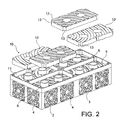
- Figs. 2 and 3 are respective exploded views of a second embodiment of apparatus according to the invention, respectively exploded and assembled; and
- Fig. 4 is a perspective assembled view of a system embodying apparatus according to the invention.
-
- Referring to the drawings, in which like parts are referred to by like numerals there is shown
apparatus base unit 2 to receive a fluid, having abase 3 andboundary walls 4 rising therefrom to define anopen top 5, opposite thebase 3 and a substantiallyplanar closure 6 for theopen top 5, whichclosure 6 is adapted for passage of fluid therethrough, there being respective means 7, 8 of thebase unit 2 andclosure 6 for interengagement of the base unit and closure whereby when the interengagement means 7, 8 are interengaged, a closedunit 9 is obtained. - It will be understood that reference to a 'closed' unit refers to the assembly of
base unit 2 andclosure 6, the base,boundary walls 4 andclosure 6 being, in the embodiments, perforated, or having through passages defined therein for passage therethrough of water when theapparatus 9 comprises a module of a storm water infiltration system or of heated air when the apparatus is a module of a crop drying floor. - In the embodiments, both the
base unit 2 andclosure 6 are formed as by moulding, for example injection moulding of plastic to provide a rigid structure. - The "perforations" in the
base 3,boundary walls 4 andclosure 6 are formed during the moulding process. - The interengagement means 7 of the
base unit 2 comprise an array of integral formed male members, suitably tubular columns, the disposition of the array being similar to that of the interengagement means 8 of theclosure 6, which are integrally formed female members or tubes depending from a grid forming a body of theclosure 6. - To assemble the
base unit 2 andclosure 6, the respective male 7, 8 and female members are interengaged, after offering up theclosure 6 to thebase unit 2. - As shown in Figs. 2, 3, in the
embodiment 10 theclosure 6 can be reversed so that the female interconnection means 8 are upstanding from the grid, themale columns 7 on assembly entering the bases thereof. Thefemale tubes 8 then definespaces 11 in whichinserts 12 can be inserted, there beingcomplementary parts 13 of theinserts 12 which mate with a part of the external surface of anadjacent tube 8 to form a complete paved surface provided by the inserts, which may be formed of any suitable material such as rubber, reclaimed rubber, plastic, brick, concrete or the like. The upper, in use, surface of theinserts 12 may have a suitable surface configuration 14 or finish to provide an aesthetic and/or functional, e.g. gripping, effect. - The
inserts 12 can be replaced singly, when damaged, and moreover form essentially a false floor in combination with a module formed from an assembled base unit and closure. - Fig. 4 shows a system built up from a series of modules, which are tied together by offset or overlapping
closures 6. - In all the embodiments, there is provided a relatively shallow apparatus (in Fig. 1 the base unit could be 200mm deep and the closure 50mm) which can be placed in a suitable excavation so that the upper in use surface of the
closure 6, or inserts 12, is flush with surrounding ground or structures for example providing a walkway around a dwelling drainage. In this case a void may be left open or filled with say gravel. - It will be understood that modifications are possible. Thus the
columns 7 of thebase unit 3 could be separate items which could be screwed into position on the base. Thebase units 3 can be stacked, and, in Fig. 4, theclosure 6 orinserts 12 could be of varied structures to provide for varied desired surface finishes. - Also, a
module - 1. A crop-drying floor where the modules are laid to form a false floor with some sort of cover put over them. The crop such as grain is placed on to this floor and then hot/cold air is blown under the floor. This air then forces itself up through the cover and filtrates through the crop, which has the effect of drying it.
- 2. The module could be laid under a driveway or path and used to clear the surface laid above from ice or snow in the winter. This could be done with the use of hot air, which in turn would be blown into the void created by the module thus heating up the area below the path or driveway that would in turn heat up the surface above it. This could provide a valuable service for the elderly or disabled during the winter months.
- 3. The module could be laid around houses as a multipurpose conduit in which electrical ducting and mains water piping could be run through. This would allow for maintenance points to be put in as well as segregating the majority of houses important connections into one place.
- 4. Using a shape other than a rectangle as the bases of the cell (e.g. a cross or a tube).
-
Claims (17)
- Apparatus for providing through flow of a fluid, comprising a base unit which is adapted to receive a fluid, having a base, and boundary walls rising therefrom to define an open top, characterised by a substantially planar closure (6) for the open top, by the closure (6) being adapted for passage of fluid therethrough, and by there being respective means (7, 8) of the base unit (2) and closure (6) for interengagement of the base unit (2) and closure (6), whereby when the interengagement means (7, 8) are interengaged, a closed unit is obtained.
- Apparatus according to claim 1, characterised by the closure (6) being perforated.
- Apparatus according to claim 1 or claim 2, characterised by the closure (6) comprising a grid which supports the respective interengagement means of the closure.
- Apparatus according to claim 3, characterised by the said means (7, 8) comprising a plurality of spaced members (8) depending from the grid (6) and laid out in a desired array.
- Apparatus according to claim 4, characterised by the respective interengagement means (7) of the base unit (2) comprising spaced upright members rising from the base and laid out in an array corresponding with the desired array of the closure (6).
- Apparatus according to claim 5, characterised by the members (8) of the closure (6) being female members and by the members (7) of the base unit (2) being male members.
- Apparatus according to any of claims 4 to 6, characterised by the closure (6) being reversible so that the members (6) define spaces (11), and there being a plurality of inserts (12) which can be inserted into the spaces (11) to provide a generally planar surface.
- Apparatus according to claim 7, characterised by each insert (12) having a part complementary in shape to a part of a respective member of the closure, and substantially of the same height thereas whereby to form a substantially planar surface.
- Apparatus according to Claim 8, characterised by the female members (8) being tubular to provide fluid access to/from the base unit.
- Apparatus according to any of claims 7 to 9, characterised by each insert (11) being selected from a group of materials comprising plastic, rubber, reclaimed rubber and concrete.
- Apparatus according to claim 10, characterised by the inserts (11) being made by moulding.
- Apparatus according to claim 11, characterised by the surface of an insert (11) remote from the interior of the apparatus being moulded with a desired surface pattern or finish (14).
- Apparatus according to any preceding claim, characterised by comprising a storm water infiltration module.
- Apparatus according to claim 13, characterised by the module comprising part of a paving system round a dwelling, swimming pool or under a path, road or drive.
- Apparatus according to any of claims 1 to 12, characterised by comprising a crop-drying floor, suitably for grain.
- A system, characterised by utilising a plurality of apparatus according to any preceding claim.
- A system according to claim 16, characterised by the respective closure units (6) of adjacent base units being offset or overlapped whereby to tie the system together.
Applications Claiming Priority (2)
| Application Number | Priority Date | Filing Date | Title |
|---|---|---|---|
| GB0308587A GB0308587D0 (en) | 2003-04-14 | 2003-04-14 | Apparatus and system for through flow of a fluid |
| GB0308587 | 2003-04-14 |
Publications (3)
| Publication Number | Publication Date |
|---|---|
| EP1469133A2 true EP1469133A2 (en) | 2004-10-20 |
| EP1469133A3 EP1469133A3 (en) | 2006-01-04 |
| EP1469133B1 EP1469133B1 (en) | 2014-03-19 |
Family
ID=9956753
Family Applications (1)
| Application Number | Title | Priority Date | Filing Date |
|---|---|---|---|
| EP20040252163 Expired - Lifetime EP1469133B1 (en) | 2003-04-14 | 2004-04-13 | Apparatus and system for through flow of a fluid |
Country Status (2)
| Country | Link |
|---|---|
| EP (1) | EP1469133B1 (en) |
| GB (1) | GB0308587D0 (en) |
Cited By (9)
| Publication number | Priority date | Publication date | Assignee | Title |
|---|---|---|---|---|
| GB2440398A (en) * | 2006-07-25 | 2008-01-30 | Polypipe Civils Ltd | Ground water system |
| GB2444550A (en) * | 2006-12-05 | 2008-06-11 | Source Control Systems Ltd | Modular storage and infiltration system for liquids |
| EP1997970A1 (en) * | 2007-05-30 | 2008-12-03 | Sogemap Injection | Water recovery system |
| WO2011007128A1 (en) * | 2009-07-13 | 2011-01-20 | Permavoid Limited | Surfaces using structural modules |
| DE102009044412A1 (en) | 2009-10-05 | 2011-04-07 | Aco Severin Ahlmann Gmbh & Co. Kg | trench body |
| US8292117B2 (en) | 2008-04-02 | 2012-10-23 | Aliaxis Participations | Stackable water holding tank |
| EP2687642A1 (en) * | 2012-07-17 | 2014-01-22 | Sell Kunststoffen B.V. | Irrigation and/or drainage assembly |
| WO2020022888A1 (en) | 2018-07-27 | 2020-01-30 | Wavin B.V. | A system and a method for building a road |
| WO2023065647A1 (en) * | 2021-10-20 | 2023-04-27 | 陈瑞文 | Photoelectric water-permeable pavement underground water storage automation system |
Families Citing this family (3)
| Publication number | Priority date | Publication date | Assignee | Title |
|---|---|---|---|---|
| CN115787381B (en) * | 2021-09-10 | 2025-11-07 | 陈瑞文 | High-strength road adapting to climate change water resource |
| CA3234672A1 (en) | 2021-10-07 | 2023-04-13 | Advanced Drainage Systems, Inc. | Stormwater management crate assembly |
| MX2024007958A (en) | 2021-12-30 | 2024-07-10 | Advanced Drainage Syst | Stormwater box with trusses. |
Citations (1)
| Publication number | Priority date | Publication date | Assignee | Title |
|---|---|---|---|---|
| US5373661A (en) | 1992-04-24 | 1994-12-20 | Yugen Kaisha Clean Up System | Particularly, a structured body for the drainage treatment for the preparation for tree-planting ground, and its impounding and flushing system |
Family Cites Families (3)
| Publication number | Priority date | Publication date | Assignee | Title |
|---|---|---|---|---|
| FR2744154B1 (en) * | 1996-01-30 | 1998-04-30 | Boissie Chantal | INSULATION AND FLOOR DRAINAGE SYSTEM |
| NL1008627C2 (en) * | 1998-03-18 | 1999-09-21 | Wavin Bv | Irrigation and / or drainage tray. |
| DE20105694U1 (en) * | 2001-03-31 | 2001-10-11 | Hauraton Betonwarenfabrik GmbH & Co KG, 76437 Rastatt | Water storage and retention system |
-
2003
- 2003-04-14 GB GB0308587A patent/GB0308587D0/en not_active Ceased
-
2004
- 2004-04-13 EP EP20040252163 patent/EP1469133B1/en not_active Expired - Lifetime
Patent Citations (1)
| Publication number | Priority date | Publication date | Assignee | Title |
|---|---|---|---|---|
| US5373661A (en) | 1992-04-24 | 1994-12-20 | Yugen Kaisha Clean Up System | Particularly, a structured body for the drainage treatment for the preparation for tree-planting ground, and its impounding and flushing system |
Cited By (15)
| Publication number | Priority date | Publication date | Assignee | Title |
|---|---|---|---|---|
| EP1887145A1 (en) * | 2006-07-25 | 2008-02-13 | Polypipe Civils Limited | Box-like drainage element |
| GB2440398A (en) * | 2006-07-25 | 2008-01-30 | Polypipe Civils Ltd | Ground water system |
| GB2444550A (en) * | 2006-12-05 | 2008-06-11 | Source Control Systems Ltd | Modular storage and infiltration system for liquids |
| EP1997970A1 (en) * | 2007-05-30 | 2008-12-03 | Sogemap Injection | Water recovery system |
| FR2916774A1 (en) * | 2007-05-30 | 2008-12-05 | Sogemap Injectin Soc Par Actio | REINFORCING PLATE FOR WATER RECOVERY CELL |
| US8292117B2 (en) | 2008-04-02 | 2012-10-23 | Aliaxis Participations | Stackable water holding tank |
| WO2011007128A1 (en) * | 2009-07-13 | 2011-01-20 | Permavoid Limited | Surfaces using structural modules |
| US8790037B2 (en) | 2009-07-13 | 2014-07-29 | Permavoid Limited | Surfaces using structural modules |
| DE102009044412A1 (en) | 2009-10-05 | 2011-04-07 | Aco Severin Ahlmann Gmbh & Co. Kg | trench body |
| WO2011042415A1 (en) | 2009-10-05 | 2011-04-14 | Aco Severin Ahlmann Gmbh & Co. Kg | Drainage body |
| DE202010018411U1 (en) | 2009-10-05 | 2016-07-07 | ACO Severin Ahlmann GmbH & Co Kommanditgesellschaft | trench body |
| EP2687642A1 (en) * | 2012-07-17 | 2014-01-22 | Sell Kunststoffen B.V. | Irrigation and/or drainage assembly |
| WO2020022888A1 (en) | 2018-07-27 | 2020-01-30 | Wavin B.V. | A system and a method for building a road |
| WO2023065647A1 (en) * | 2021-10-20 | 2023-04-27 | 陈瑞文 | Photoelectric water-permeable pavement underground water storage automation system |
| JP2024532548A (en) * | 2021-10-20 | 2024-09-05 | 陳瑞文 | Photoelectric permeable pavement underground water storage automation system |
Also Published As
| Publication number | Publication date |
|---|---|
| EP1469133A3 (en) | 2006-01-04 |
| GB0308587D0 (en) | 2003-05-21 |
| EP1469133B1 (en) | 2014-03-19 |
Similar Documents
| Publication | Publication Date | Title |
|---|---|---|
| US7503726B2 (en) | Subsurface drainage system and drain structure therefor | |
| CA2286336C (en) | Subsurface fluid drainage and storage systems | |
| KR101509202B1 (en) | Side Gutter Type Rain Collecting Well AND Eco-friendly Road Structure With Drainage System Using The Rain Collecting Wells | |
| EP1469133B1 (en) | Apparatus and system for through flow of a fluid | |
| US20100226721A1 (en) | Module and Assembly for Managing the Flow of Water | |
| US7201538B2 (en) | Subsurface drainage system and drain structure therefor | |
| US20050100412A1 (en) | Drainage support apparatus | |
| KR101147512B1 (en) | Direct drain type water treatment and storage facilities for grounds, strorage block, and drain block | |
| JPH0426648B2 (en) | ||
| KR102305411B1 (en) | Rain water storage device | |
| KR102612755B1 (en) | Modules and assemblies for subsurface management of fluids used in low-depth applications | |
| KR102154399B1 (en) | Drainage system | |
| CN109563701B (en) | Modular Rainwater Retention System | |
| WO1998044210A1 (en) | Auxiliary devices for the improvement of the drainage by integrating the system of separation of rainfall waters from sewage waters | |
| CN218405756U (en) | Rainwater grate | |
| KR101878286B1 (en) | Rainwater recycling facility having segment built-up-type PC block and landscape tree rainwater recycling facility system of the same | |
| AU2006202126B2 (en) | Water storage system | |
| HK40054138A (en) | Module and assembly for underground management of fluids for shallow-depth applications | |
| ES2820546B2 (en) | Urban drainage system | |
| JPH11107353A (en) | Rain water reservoir tank | |
| KR200346107Y1 (en) | Gutter with boundary stones | |
| MXPA97002364A (en) | Auxiliary devices to improve the operation of the drainage that comprises the system of separation of black and pluvian waters | |
| AU2006222739A1 (en) | Water storage system | |
| JPH0618425U (en) | Snow removal structure |
Legal Events
| Date | Code | Title | Description |
|---|---|---|---|
| PUAI | Public reference made under article 153(3) epc to a published international application that has entered the european phase |
Free format text: ORIGINAL CODE: 0009012 |
|
| AK | Designated contracting states |
Kind code of ref document: A2 Designated state(s): AT BE BG CH CY CZ DE DK EE ES FI FR GB GR HU IE IT LI LU MC NL PL PT RO SE SI SK TR |
|
| AX | Request for extension of the european patent |
Extension state: AL HR LT LV MK |
|
| PUAL | Search report despatched |
Free format text: ORIGINAL CODE: 0009013 |
|
| AK | Designated contracting states |
Kind code of ref document: A3 Designated state(s): AT BE BG CH CY CZ DE DK EE ES FI FR GB GR HU IE IT LI LU MC NL PL PT RO SE SI SK TR |
|
| AX | Request for extension of the european patent |
Extension state: AL HR LT LV MK |
|
| 17P | Request for examination filed |
Effective date: 20060704 |
|
| AKX | Designation fees paid |
Designated state(s): AT BE BG CH CY CZ DE DK EE ES FI FR GB GR HU IE IT LI LU MC NL PL PT RO SE SI SK TR |
|
| 17Q | First examination report despatched |
Effective date: 20081117 |
|
| RAP1 | Party data changed (applicant data changed or rights of an application transferred) |
Owner name: POLYPIPE LIMITED |
|
| GRAP | Despatch of communication of intention to grant a patent |
Free format text: ORIGINAL CODE: EPIDOSNIGR1 |
|
| INTG | Intention to grant announced |
Effective date: 20130930 |
|
| RIN1 | Information on inventor provided before grant (corrected) |
Inventor name: SINGLETON, JASON Inventor name: RAMELLA, STUART Inventor name: COUPE, KEVIN |
|
| GRAS | Grant fee paid |
Free format text: ORIGINAL CODE: EPIDOSNIGR3 |
|
| GRAA | (expected) grant |
Free format text: ORIGINAL CODE: 0009210 |
|
| RIN1 | Information on inventor provided before grant (corrected) |
Inventor name: COUPE, KEVIN Inventor name: SHINGLETON, JASON Inventor name: RAMELLA, STUART |
|
| AK | Designated contracting states |
Kind code of ref document: B1 Designated state(s): AT BE BG CH CY CZ DE DK EE ES FI FR GB GR HU IE IT LI LU MC NL PL PT RO SE SI SK TR |
|
| REG | Reference to a national code |
Ref country code: GB Ref legal event code: FG4D |
|
| REG | Reference to a national code |
Ref country code: CH Ref legal event code: EP |
|
| REG | Reference to a national code |
Ref country code: IE Ref legal event code: FG4D |
|
| REG | Reference to a national code |
Ref country code: AT Ref legal event code: REF Ref document number: 657802 Country of ref document: AT Kind code of ref document: T Effective date: 20140415 |
|
| REG | Reference to a national code |
Ref country code: DE Ref legal event code: R096 Ref document number: 602004044625 Country of ref document: DE Effective date: 20140430 |
|
| REG | Reference to a national code |
Ref country code: NL Ref legal event code: VDEP Effective date: 20140319 |
|
| REG | Reference to a national code |
Ref country code: AT Ref legal event code: MK05 Ref document number: 657802 Country of ref document: AT Kind code of ref document: T Effective date: 20140319 |
|
| PG25 | Lapsed in a contracting state [announced via postgrant information from national office to epo] |
Ref country code: FI Free format text: LAPSE BECAUSE OF FAILURE TO SUBMIT A TRANSLATION OF THE DESCRIPTION OR TO PAY THE FEE WITHIN THE PRESCRIBED TIME-LIMIT Effective date: 20140319 Ref country code: SE Free format text: LAPSE BECAUSE OF FAILURE TO SUBMIT A TRANSLATION OF THE DESCRIPTION OR TO PAY THE FEE WITHIN THE PRESCRIBED TIME-LIMIT Effective date: 20140319 Ref country code: CY Free format text: LAPSE BECAUSE OF FAILURE TO SUBMIT A TRANSLATION OF THE DESCRIPTION OR TO PAY THE FEE WITHIN THE PRESCRIBED TIME-LIMIT Effective date: 20140319 |
|
| PG25 | Lapsed in a contracting state [announced via postgrant information from national office to epo] |
Ref country code: BE Free format text: LAPSE BECAUSE OF FAILURE TO SUBMIT A TRANSLATION OF THE DESCRIPTION OR TO PAY THE FEE WITHIN THE PRESCRIBED TIME-LIMIT Effective date: 20140319 Ref country code: BG Free format text: LAPSE BECAUSE OF FAILURE TO SUBMIT A TRANSLATION OF THE DESCRIPTION OR TO PAY THE FEE WITHIN THE PRESCRIBED TIME-LIMIT Effective date: 20140619 Ref country code: EE Free format text: LAPSE BECAUSE OF FAILURE TO SUBMIT A TRANSLATION OF THE DESCRIPTION OR TO PAY THE FEE WITHIN THE PRESCRIBED TIME-LIMIT Effective date: 20140319 Ref country code: RO Free format text: LAPSE BECAUSE OF FAILURE TO SUBMIT A TRANSLATION OF THE DESCRIPTION OR TO PAY THE FEE WITHIN THE PRESCRIBED TIME-LIMIT Effective date: 20140319 Ref country code: NL Free format text: LAPSE BECAUSE OF FAILURE TO SUBMIT A TRANSLATION OF THE DESCRIPTION OR TO PAY THE FEE WITHIN THE PRESCRIBED TIME-LIMIT Effective date: 20140319 Ref country code: CZ Free format text: LAPSE BECAUSE OF FAILURE TO SUBMIT A TRANSLATION OF THE DESCRIPTION OR TO PAY THE FEE WITHIN THE PRESCRIBED TIME-LIMIT Effective date: 20140319 |
|
| REG | Reference to a national code |
Ref country code: DE Ref legal event code: R119 Ref document number: 602004044625 Country of ref document: DE |
|
| PG25 | Lapsed in a contracting state [announced via postgrant information from national office to epo] |
Ref country code: ES Free format text: LAPSE BECAUSE OF FAILURE TO SUBMIT A TRANSLATION OF THE DESCRIPTION OR TO PAY THE FEE WITHIN THE PRESCRIBED TIME-LIMIT Effective date: 20140319 Ref country code: PL Free format text: LAPSE BECAUSE OF FAILURE TO SUBMIT A TRANSLATION OF THE DESCRIPTION OR TO PAY THE FEE WITHIN THE PRESCRIBED TIME-LIMIT Effective date: 20140319 Ref country code: SK Free format text: LAPSE BECAUSE OF FAILURE TO SUBMIT A TRANSLATION OF THE DESCRIPTION OR TO PAY THE FEE WITHIN THE PRESCRIBED TIME-LIMIT Effective date: 20140319 Ref country code: MC Free format text: LAPSE BECAUSE OF FAILURE TO SUBMIT A TRANSLATION OF THE DESCRIPTION OR TO PAY THE FEE WITHIN THE PRESCRIBED TIME-LIMIT Effective date: 20140319 Ref country code: AT Free format text: LAPSE BECAUSE OF FAILURE TO SUBMIT A TRANSLATION OF THE DESCRIPTION OR TO PAY THE FEE WITHIN THE PRESCRIBED TIME-LIMIT Effective date: 20140319 |
|
| REG | Reference to a national code |
Ref country code: CH Ref legal event code: PL |
|
| PG25 | Lapsed in a contracting state [announced via postgrant information from national office to epo] |
Ref country code: PT Free format text: LAPSE BECAUSE OF FAILURE TO SUBMIT A TRANSLATION OF THE DESCRIPTION OR TO PAY THE FEE WITHIN THE PRESCRIBED TIME-LIMIT Effective date: 20140721 |
|
| REG | Reference to a national code |
Ref country code: DE Ref legal event code: R119 Ref document number: 602004044625 Country of ref document: DE Effective date: 20141101 |
|
| PLBE | No opposition filed within time limit |
Free format text: ORIGINAL CODE: 0009261 |
|
| STAA | Information on the status of an ep patent application or granted ep patent |
Free format text: STATUS: NO OPPOSITION FILED WITHIN TIME LIMIT |
|
| PG25 | Lapsed in a contracting state [announced via postgrant information from national office to epo] |
Ref country code: DE Free format text: LAPSE BECAUSE OF NON-PAYMENT OF DUE FEES Effective date: 20141101 Ref country code: LI Free format text: LAPSE BECAUSE OF NON-PAYMENT OF DUE FEES Effective date: 20140430 Ref country code: CH Free format text: LAPSE BECAUSE OF NON-PAYMENT OF DUE FEES Effective date: 20140430 Ref country code: DK Free format text: LAPSE BECAUSE OF FAILURE TO SUBMIT A TRANSLATION OF THE DESCRIPTION OR TO PAY THE FEE WITHIN THE PRESCRIBED TIME-LIMIT Effective date: 20140319 |
|
| 26N | No opposition filed |
Effective date: 20141222 |
|
| PG25 | Lapsed in a contracting state [announced via postgrant information from national office to epo] |
Ref country code: IT Free format text: LAPSE BECAUSE OF FAILURE TO SUBMIT A TRANSLATION OF THE DESCRIPTION OR TO PAY THE FEE WITHIN THE PRESCRIBED TIME-LIMIT Effective date: 20140319 |
|
| PG25 | Lapsed in a contracting state [announced via postgrant information from national office to epo] |
Ref country code: SI Free format text: LAPSE BECAUSE OF FAILURE TO SUBMIT A TRANSLATION OF THE DESCRIPTION OR TO PAY THE FEE WITHIN THE PRESCRIBED TIME-LIMIT Effective date: 20140319 |
|
| REG | Reference to a national code |
Ref country code: FR Ref legal event code: PLFP Year of fee payment: 13 |
|
| PG25 | Lapsed in a contracting state [announced via postgrant information from national office to epo] |
Ref country code: GR Free format text: LAPSE BECAUSE OF FAILURE TO SUBMIT A TRANSLATION OF THE DESCRIPTION OR TO PAY THE FEE WITHIN THE PRESCRIBED TIME-LIMIT Effective date: 20140620 |
|
| PG25 | Lapsed in a contracting state [announced via postgrant information from national office to epo] |
Ref country code: LU Free format text: LAPSE BECAUSE OF NON-PAYMENT OF DUE FEES Effective date: 20140413 Ref country code: TR Free format text: LAPSE BECAUSE OF FAILURE TO SUBMIT A TRANSLATION OF THE DESCRIPTION OR TO PAY THE FEE WITHIN THE PRESCRIBED TIME-LIMIT Effective date: 20140319 Ref country code: HU Free format text: LAPSE BECAUSE OF FAILURE TO SUBMIT A TRANSLATION OF THE DESCRIPTION OR TO PAY THE FEE WITHIN THE PRESCRIBED TIME-LIMIT; INVALID AB INITIO Effective date: 20040413 |
|
| REG | Reference to a national code |
Ref country code: FR Ref legal event code: PLFP Year of fee payment: 14 |
|
| REG | Reference to a national code |
Ref country code: FR Ref legal event code: PLFP Year of fee payment: 15 |
|
| REG | Reference to a national code |
Ref country code: FR Ref legal event code: PLFP Year of fee payment: 20 |
|
| P01 | Opt-out of the competence of the unified patent court (upc) registered |
Effective date: 20230530 |
|
| PGFP | Annual fee paid to national office [announced via postgrant information from national office to epo] |
Ref country code: IE Payment date: 20230412 Year of fee payment: 20 Ref country code: FR Payment date: 20230411 Year of fee payment: 20 |
|
| PGFP | Annual fee paid to national office [announced via postgrant information from national office to epo] |
Ref country code: GB Payment date: 20230406 Year of fee payment: 20 |
|
| REG | Reference to a national code |
Ref country code: GB Ref legal event code: PE20 Expiry date: 20240412 |
|
| REG | Reference to a national code |
Ref country code: IE Ref legal event code: MK9A |
|
| PG25 | Lapsed in a contracting state [announced via postgrant information from national office to epo] |
Ref country code: IE Free format text: LAPSE BECAUSE OF EXPIRATION OF PROTECTION Effective date: 20240413 |
|
| PG25 | Lapsed in a contracting state [announced via postgrant information from national office to epo] |
Ref country code: GB Free format text: LAPSE BECAUSE OF EXPIRATION OF PROTECTION Effective date: 20240412 |
|
| PG25 | Lapsed in a contracting state [announced via postgrant information from national office to epo] |
Ref country code: IE Free format text: LAPSE BECAUSE OF EXPIRATION OF PROTECTION Effective date: 20240413 Ref country code: GB Free format text: LAPSE BECAUSE OF EXPIRATION OF PROTECTION Effective date: 20240412 |