EP1468895B1 - Steering device - Google Patents
Steering device Download PDFInfo
- Publication number
- EP1468895B1 EP1468895B1 EP02775353A EP02775353A EP1468895B1 EP 1468895 B1 EP1468895 B1 EP 1468895B1 EP 02775353 A EP02775353 A EP 02775353A EP 02775353 A EP02775353 A EP 02775353A EP 1468895 B1 EP1468895 B1 EP 1468895B1
- Authority
- EP
- European Patent Office
- Prior art keywords
- brackets
- column
- steering apparatus
- tension member
- pair
- Prior art date
- Legal status (The legal status is an assumption and is not a legal conclusion. Google has not performed a legal analysis and makes no representation as to the accuracy of the status listed.)
- Expired - Fee Related
Links
Images


Classifications
-
- B—PERFORMING OPERATIONS; TRANSPORTING
- B62—LAND VEHICLES FOR TRAVELLING OTHERWISE THAN ON RAILS
- B62D—MOTOR VEHICLES; TRAILERS
- B62D1/00—Steering controls, i.e. means for initiating a change of direction of the vehicle
- B62D1/02—Steering controls, i.e. means for initiating a change of direction of the vehicle vehicle-mounted
- B62D1/16—Steering columns
- B62D1/18—Steering columns yieldable or adjustable, e.g. tiltable
- B62D1/187—Steering columns yieldable or adjustable, e.g. tiltable with tilt adjustment; with tilt and axial adjustment
-
- B—PERFORMING OPERATIONS; TRANSPORTING
- B62—LAND VEHICLES FOR TRAVELLING OTHERWISE THAN ON RAILS
- B62D—MOTOR VEHICLES; TRAILERS
- B62D1/00—Steering controls, i.e. means for initiating a change of direction of the vehicle
- B62D1/02—Steering controls, i.e. means for initiating a change of direction of the vehicle vehicle-mounted
- B62D1/16—Steering columns
- B62D1/18—Steering columns yieldable or adjustable, e.g. tiltable
- B62D1/184—Mechanisms for locking columns at selected positions
Definitions
- the present invention relates to a steering apparatus.
- An embodiment relates to a tilt/telescopic type steering apparatus capable of adjusting a tilt angle of a steering wheel and an axis-directional position thereof, corresponding to a driving posture (position) of a driver.
- a steering apparatus for an automotive vehicle is a tilt/telescopic type steering apparatus capable of adjusting a tilt angle of a steering wheel and an axis-directional position of the steering wheel, corresponding to a physique and a driving posture of a driver.
- Japanese Patent Application Laid-Open No. 2001-191927 discloses a steering apparatus constructed such that support members disposed within a steering column are interposed between a pair of brackets and are displaced along tilt grooves formed in the brackets or along telescopic grooves formed in the steering column, and this causes the two brackets to get displaced in the same direction, thereby adjusting a tilt angle and an axis-directional displacement of the steering shaft supported rotatably with respect to the steering column.
- the steering column is fixed by pushing one bracket against the steering column via an intermediate member, however, at this time, the other bracket is pushed via the support member, and this might cause an axis deviation of the steering shaft.
- a rigidity of the other bracket must be increased for preventing the axis direction, however, this might induce rises both in weight and in costs.
- a presumable construction is that the two brackets are pressed from both sides against the steering column, however, this construction involves such a laborious operation that the driver must rotate two pieces of levers by hands, and there arises a problem in which the operability declines.
- GB 2 295 445 relates to an adjustable steering column in which a steering shaft is mounted within a column tube secured to a vehicle by bracket members. Slots, preferably in anti-friction elements, are provided to provide adjustment between the tube and bracket.
- the pair of brackets gets close to each other by dint of the displacement caused by the displacement causing member, with the result that a distance between the brackets decreases.
- the outer column is thereby held between the tension member and the brackets.
- the displaced brackets apply a pressing force to the inner column via the pressing portion of the outer column, whereby the inner column is held by the brackets connected to the car body through the outer column.
- the steering shaft can be therefore fixed in the telescoping direction.
- the pair of brackets is connected to the tension member, and hence, if the two brackets take approximately a symmetrical configuration with respect to the steering shaft interposed therebetween, displaced quantities of the respective brackets are equalized.
- a central position of the inner column can be thereby kept substantially fixed, so that the axis deviation of the steering shaft can be effectively restrained.
- a preferable arrangement is that when a line connecting centers of the two fixing members intersects an axis of the inner column (or the steering shaft), the pressing force can be applied uniformly to the inner column.
- the outer column formed with slits disposed upwards and downwards with the steering shaft interposed therebetween the outer column can be made to deform by a smaller force in order to hold the inner column.
- an axis of the steering shaft substantially intersects a line that connects centers of the two fixing members.
- the pair of brackets is preferably formed with tilt grooves, whereby, for example, the inner column can be tilted together with the outer column.
- the outer column preferably includes an integrally-formed car body fitting portion, such that the inner column can be held on the car body through the outer column.
- part of the inner column is formed with at least one elongate hole extending in an axis-direction
- an inner peripheral surface of the outer column is preferably formed with a protruded portion engaging with the elongate hole and extending inwards in a radial direction, such that the inner column can be telescoped (displaced in the axis-direction).
- one of the inner column and the outer column is provided with a protruded portion extending in a radial direction, and, when the inner column and the outer column make their displacements in the axis-directions, the protruded portion abuts on the other of the inner column and the outer column and is thus made to function as a telescopic stopper for blocking a further displacement. With this contrivance, the inner column can be restrained from coming off the outer column.
- the tension member is constructed of a plurality of parts that can be divided so as to form an annular configuration embracing the outer column, such that the assembly is facilitated.
- said tension member is disposed radially outwardly of said inner column.
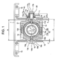
- FIG. 1 is a cross-sectional view of the tilt/telescopic type steering apparatus according to a first embodiment of the present invention.
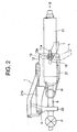
- FIG. 2 is a side view of the steering apparatus shown in FIG. 1 .
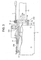
- FIG. 3 is a top view of the steering apparatus shown in FIG. 1 .
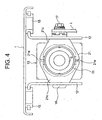
- FIG. 4 is a view of the steering apparatus shown in FIG. 2 as viewed in an arrowhead-direction III.
- brackets 12 each composed of a plate material bent in an L-shape, are attached through a pair of release capsules 15 to a top plate 1 secured to an unillustrated car body.
- a plate thickness of each of the brackets 12 is the same, and the brackets 12 take a configuration exhibiting a line symmetry with respect to a perpendicular line.
- the release capsule 15, upon a secondary collision, functions such that the release capsule 15 gets collapsed when an impact load acts on a steering column towards the front of the vehicle, and gets released together with the car body sided bracket 12 from the car body, thereby enabling the steering column to get displaced towards the front of the vehicle.
- a tension member 13 is disposed between the brackets 12, 12.
- the tension member 13 is a member taking substantially an annular shape in its assembled state.
- the tension member 13 can be divided at its center into two parts, i.e., a left-half tension member 13a and a right-half tension member 13b.
- two pieces of bolts 14, 14 inserted through a screw hole 13c formed in the left-half tension member 13a and a screw hole 13d formed in the right-half tension member 13b are fastened, thereby assembling the left-half tension member 13a and the right-half tension member 13b together.
- the tension member 13 can be thus acquired.
- the left- and right-half tension members 13a, 13b remain separated before being mounted in the real car and made integral with each other when mounted in the real car by use of a bolt 14, thereby enabling the assembly to be more facilitated.
- a cylindrical inner column 11 is disposed inwardly of the tension member 13.
- a steering shaft S is inserted through within the inner column 11 and is rotatably supported via an unillustrated bearing within the inner column 11.
- Telescopic grooves 11a are, as illustrated in FIG. 2 , formed as elongate holes in parallel with the axis of the steering shaft S on both sides of the inner column 11.
- the bracket 12 is formed with a tilt groove 12a serving as part of a circular arc depicted when the steering shaft S is tilted about a pivotal motion point P, and, in the assembled state, the telescopic groove 11a and the tilt groove 12a are partly overlapped with each other as viewed in the direction shown in FIG. 2 .
- a fixing member 16 is so inserted from the left side in FIG. 1 as to penetrate the tilt groove 12a, while a fixing member 17 is inserted from the right side in FIG. 1 .
- Axes of the fixing members 16, 17 substantially intersect (actually intersect or extend in the vicinity of) the axis of the steering shaft S.
- the fixing member 16 includes a disc-like head portion 16a larger than a width of the tilt groove 12 on the left side in FIG. 1 , an angular-pole-like tilt guided portion 16b engaging with and thus guided along within the tilt groove 12a, a male screw portion 16c screwed into a screw through-hole 13e formed in the left-half tension member 13c of the tension member 13, and an angular-pole-like telescopic guided portion 16d engaging with and thus guided along within the telescopic groove on the left side in FIG. 1 .
- the fixing member 17 includes a head portion 17a, an elongate tilt guided portion 17b taking a cylindrical shape and having a diametrical dimension slightly smaller than a width of the tilt groove 12a, a male screw portion 17c screwed into a screw through-hole 13f formed in the right-half tension member 13b of the tension member 13, and an angular-pole-like telescopic guided portion 17d engaging with and thus guided along within the telescopic groove 11a on the right side in FIG. 1 .
- telescopic guided portions 16d, 17d configure protruded portions engaging with the telescopic grooves 11a and extending inwards in the diametrical directions.
- first cam member 18 that partly engages with the telescopic groove 11a and is therefore incapable of rotating
- second cam member 19 disposed adjacent to the first cam member 18, attached to a side end portion of a lever L and rotatable together with the lever L
- bearing 20 interposed in between and held by the head portion 17a and the side end portion of the lever L.
- first cam member 18, the second cam member 19 and the lever L constitute a displacing member.
- An outer column 21 has a cylindrical portion 21a, a pair of arm portions 21b (which are car body fitting portions of which only one is shown in FIG. 3 ) extending from the cylindrical portion 21 towards the left in FIG. 2 , and a pair of flange portions 21c, 21d disposed at some interval in the axis-direction shown in FIG. 3 along an outer periphery of the right side end portion of the cylindrical portion 21a in FIG. 2 .
- the cylindrical portion 21a embraces the inner column 11, and a side end portion of the arm portion 21b so supported by a support member 22 on the unillustrated car body as to be capable of swinging about a pivotal support point O.
- the tension member 13 is disposed between the flange portions 21c, 21d serving as a pressing portion.
- cylindrical portion 21a is formed with a pair of slits 21e (appearing more exaggerated than in reality) in positions apart through 90 degrees from the fixing members 16, 17 so as to split the flange portions 21c, 21d from the right side ends thereof as shown in FIGS. 3 and 4 .
- a coil spring W is disposed between the bracket 12 and the outer column 21.
- the coil spring W biases the outer column 21 upwards in FIG. 2 towards the bracket 12, thereby canceling a self-weight of the unillustrated steering wheel, etc. attached to the right side end of the steering shaft S.
- the outer column 21 is thereby fixed to the brackets 12, with the result that tilt-directional displacement of the inner column 11 is blocked.
- the two brackets 12 have substantially the same configuration and the plate thickness, i.e., have substantially the same flexural elastic coefficient (namely, the same rigidity). Hence, the brackets 12 receive the forces in such directions as to have proximity to each other and make substantially the same amount of displacement. Then, the inner column 11 receives the pressing forces from both of the right and left sides in FIG. 1 via the flange portions 21c, 21d, and is fixed so that the center of the inner column 11 is coincident with such a position as to halve a distance between the brackets 12, 12. With this arrangement, an axis deviation of the steering shaft S can be restrained while being capable of blocking the displacement in a telescoping direction.
- the first embodiment takes the construction, wherein as the slits 21e are formed upwardly and downwardly of the outer column 21, the rigidity of the outer column 21 decreases, and the flange portions 21c, 21d are easy to get displaced in the direction towards the inner column 11.
- a requirement for attaining the operations described above is that an increment quantity ⁇ D of a distance D from the head portion 17a of the fixing member 17 to the side end surface of the bracket 12 when fastening the lever L should be, as shown in FIG. 1 , larger than a value obtained by subtracting a width B of the tension member 13 from an interval C between the brackets 12, 12 in a free state (wherein, the above value is a sum of a gap F between the right-side bracket 12 in FIG. 1 and the tension member 13 and of a gap F' between the left-side bracket 12 and the tension member 12).
- the requirement is given by ⁇ D > (F + F').
- the increment quantity ⁇ D can be adjusted by changing heights of the ride-on protruded portions (unillustrated) of the first cam member 18 and the second cam member 19.
- the tilt guided portions 16b, 17b of the fixing members 16, 17 are displaced while being guided along the tilt grooves 12a, 12a of the brackets 12, 12, or alternatively the telescopic guided portions 16d, 17d are displaced while being guided along the telescopic grooves 11a of the inner column 11, whereby the adjustment in the tilting direction and in the telescoping direction can be arbitrarily made.
- the interval C between the brackets 12 in the free state be larger than the width B of the tension member 12. Namely, the requirement is given such as C > B. It is to be noted that a value of (C - B) is changed by varying a screw-in quantity of the fixing member into the tension member 13, and it is therefore possible to adjust the pressing force between the bracket 12 and the tension member 13 when fastening the lever L.
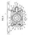
- FIG. 5 is a cross-sectional view of the tilt/telescopic type steering apparatus according to a second embodiment of the present invention.
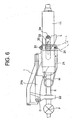
- FIG. 6 is a side view of the steering apparatus shown in FIG. 5 .
- FIG. 7 is a top view of the steering apparatus shown in FIG. 5 . It is only a different point of the second embodiment from the first embodiment shown in FIGS. 1 through 4 to provide an additional construction, and hence common components other than this difference are marked with the same numerals and symbols, of which the repetitive explanations are herein omitted.
- a plurality (which is herein represented by four pieces) of friction plates 30 receiving penetration of one of the fixing members 16, 17 and extending in vertical directions in FIG. 5 are, as shown in FIGS. 6 and 7 , disposed between the flange portions of the outer column 21 and the two brackets 12.
- the four friction plates 30 are attached to the brackets 12 by use of two pieces of caulking pins 31 but are displaceable in an axis-direction of the caulking pin 31.
- FIG. 7 similarly a plurality (which is herein represented by four pieces) of friction plates 33 receiving penetration of one of the fixing members 16, 17 and extending in horizontal directions in FIG. 7 are disposed crosswise over the individual friction plates 30 between the flange portions of the outer column 21 and the two brackets 12.
- Each set of four friction plates 33 is attached to each of both sides of the inner column 11 through a piece of pin 34 but is displaceable in an axis-direction of the pin 34.
- the outer column 21 is thereby fixed to the brackets 12 with the aide of the tremendous frictional forces of the friction plates 30 and 33, with the result that tilt-directional displacement of the inner column 11 is blocked.
- the left-side bracket 12 when getting displaced to the right, abuts on the left-half portions of the flange portions 21c, 21d via the friction plates 30, 33 and similarly displaces these portions to the right, thereby applying the pressing force to the outer peripheral surface of the inner column 11. Consequently, the tremendous frictional forces occur on the friction plates 30, 33. Namely, according to the second embodiment, the force of holding the outer column 21 can be augmented by using the friction plates 30, 33 more than in the first embodiment discussed above.
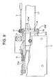
- FIG. 8 is a partially sectional side view of the tilt/telescopic type steering apparatus according to a third embodiment of the present invention.
- FIG. 9 is a top view of the steering apparatus shown in FIG. 8 . It is only a different point of the third embodiment from the first embodiment illustrated in FIGS. 1 through 4 to omit the telescopic (axis-directional) adjusting function, and hence common components other than this difference are marked with the same numerals and symbols, of which the repetitive explanations are herein omitted.
- an outer column 21' is, as shown in FIG. 8 , formed with a screw hole 21f' in its upper portion.
- a pin-attached bolt 40 is screwed into this screw hole 21f' from an outer peripheral side thereof.
- the pin-attached bolt 40 is formed with a pin portion 40a at its front side end.
- the pin portion 40a protrudes inwards in a radial direction from an inner peripheral surface of the outer column 21', and engages with an elongate hole 11c' formed in an upper portion of the inner column 11'.
- the inner column 11' has telescopic holes formed along the peripheries of the fixing members 16, 17 in the third embodiment.
- the outer column 21' is provided with the pin-attached bolt 40 as the protruded portion extending in the radial direction, and the pin portion 40a engages with the elongate hole 11c'.
- the pin-attached bolt 40 abuts on (engages with) the side end portion of the elongate hole 11c' of the inner column 11' and thus functions as a telescoping stopper for blocking further displacements thereof.
- the inner column 11' may be formed with a telescoping stopper as a protruded portion, and relative displacements may be blocked by abutting on (engaging with) the outer column 21'.
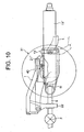
- FIG. 10 is a partially sectional side view of the tilt/telescopic type steering apparatus according to a fourth embodiment of the present invention.
- FIG. 11 is an enlarged view of a portion indicated by an arrowhead XI in a construction shown in FIG. 10 .
- the components common to those in the first through third embodiments illustrated in FIGS. 1 through 9 are marked with the same numerals and symbols, of which the repetitive explanations are herein omitted.
- a diameter-reduced portion 21h" of which a diameter is slightly reduced is formed in an inner peripheral surface in the vicinity of a right side end, as viewed in FIG. 11 , of an outer column 21". Further, a diameter-expanded portion 21g" of which a diameter is slightly expanded is formed in the inner peripheral surface in the vicinity of a left side end as viewed in FIG. 11 .
- a cylindrical retainer 41 is fitted into and thus disposed in the diameter-expanded portion 21g". A length of the retainer 41 in the axis-direction is substantially the same as a length of the diameter-expanded portion 21g" in the axis-direction.
- An inside diameter of an inner peripheral surface of the retainer 41 is substantially equal to an inside diameter of an inner peripheral surface of the diameter-reduced portion 21h" but is smaller than an inside diameter of an inner peripheral surface throughout the outer column 21" excluding the diameter-reduced portion 21h".
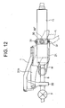
- FIG. 12 is a partially sectional side view of the tilt/telescopic type steering apparatus according to a fifth embodiment of the present invention.
- FIG. 13 is a top view of the steering apparatus shown in FIG. 12 .
- the fifth embodiment has a difference from the second embodiment illustrated in FIGS. 5 through 7 only about a point of employing circular washers 33' as a substitute for the elongate friction plates 33.
- the common components other than the circular washers are marked with the same numerals and symbols, of which the repetitive explanations are herein omitted. It should be noted that as the friction plates 33 are replaced by the washers 33', the pins 34 are also omitted.
- the outer column 21 in the tilting direction, even if a large load as by the secondary collision is applied due to a large frictional force acting on between the four pieces of friction plates 30 and the washers 33' disposed crosswise over these plates, the outer column 21 can be surely held. While in the telescoping direction, none of the friction plates being provided, such a large load is received mainly by the slide resistance between the outer column 21 and the inner column 11, and hence a start-of-movement load can be restrained low. In the case of downsizing the vehicle, an entire length of the column is reduced, wherein it is difficult to ensure a sufficient collapsible stroke. According to the fifth embodiment, when the secondary collision happens, the outer column 21 can be easily slide on the inner column 11 in the telescoping direction. Therefore, even when the column itself is shortened, a merit is that the collapsible stroke can be substantially increased.
- FIG. 14 is a sectional view, similar to FIG. 1 , of a tilt type steering apparatus according to a sixth embodiment of the present invention.
- the sixth embodiment is different from the first embodiment shown in FIG. 1 chiefly about a configuration of the tension member, etc., and therefore the common components are marked with the same numerals and symbols, of which the repetitive explanations are herein omitted.
- a tension member 113 is constructed of a lower side portion 113a taking a U-shape in section and an upper side portion 113b fastened by bolts 114 that cover open areas thereof.
- Male screw portions 116c, 117c of fixing members 116, 117 are screwed into screw holes 113e, 113f formed in the lower side portion 113a, whereby the tension member 113 is secured to between the pair of brackets 12.
- the respective bolts 114 can be fastened in the same direction (from above), and hence assembling characteristics are more advantageous than in the embodiments discussed above.
- An interior space which is configured by the lower side portion 113a and the upper side portion 113b of the tension member 113, takes substantially an octagonal shape and accommodates an outer column 121 assuming substantially a C-shape in section, corresponding thereto.
- the outer column 121 is made of an aluminum material (or a magnesium material) by die casting and can therefore be, as illustrated in FIG. 14 , in an arbitrary configuration having an open area at its lower portion and having a large wall thickness on the lower side.
- a cylindrical inner column 111 taking substantially an octagonal shape in section is disposed inwardly of the outer column 121.
- the inner column 111 and the outer column 121 which are non-cylindrical in their sectional shapes, engage with each other, so that the inner column 111 can be restrained from rotating about the axis.
- the section of the inner column 111 is not limited to the octagonal shape and may take polygonal shapes other the octagon.
- FIG. 15 is a sectional view, similar to FIG. 14 , of the tilt type steering apparatus according to a seventh embodiment of the present invention.
- the seventh embodiment is different from the sixth embodiment shown in FIG. 14 mainly about a configuration of the tension member, etc., and therefore the common components are marked with the same numerals and symbols, of which the repetitive explanations are herein omitted.
- a tension member 213 is constructed of a main body 213a, of which a lower portion is open, taking an inverted U-shape in section, and a tube 213b bridged between lower side ends of both-sided walls of the main body 213a, and fixed to the main body 213a by a bolt 214 inserted through within this tube 213b.
- the male screw portions 116c, 117c of the fixing members 116, 117 are screwed into screw holes 213e, 213f formed in the main body 213a, whereby the tension member 213 is secured to between the pair of brackets 12.
- the bolt 214 may involve the use of a standard bolt.
- the tube 213b can be manufactured simply by cutting an annular tube to a predetermined length, thereby attaining a lower-cost scheme. Note that tube 213b may be manufactured by rounding a plate material.
- annular-tube-like outer column 221 with its lowermost portion notched in the axis-direction, is disposed in an interior of the tension member 213.
- the outer column 221, of which an uppermost portion is small in its wall thickness and of which the lowermost portion is notched, is therefore capable of easily deforming in a diameter reducing direction.
- the annular-tube-like inner column 111 is disposed within the outer column 221.
- FIG. 16 is a sectional view, similar to FIG. 15 , of the tilt type steering apparatus according to an eighth embodiment of the present invention.
- the eighth embodiment is different from the seventh embodiment shown in FIG. 15 mainly about a configuration of the tension member, etc., and therefore the common components are marked with the same numerals and symbols, of which the repetitive explanations are herein omitted.
- a tension member 313 is constructed of a main body 313a, of which a lower portion is open, taking an inverted U-shape in section, and a bolt 314 for connecting both-sided walls of the main body 313a.
- the bolt 314 includes a screw portion 314a screwed into one side wall (on the left side in FIG. 16 ), and a thick rod portion 314b having a stepped portion contiguous to the screw portion 314a.
- the bolt 314 itself structures part of the tension member 313. As the stepped portion of the thick rod portion 314b abuts on the side wall of the main body 313a, an interval between the walls on both sides becomes fixed by fastening the bolt 314.
- the tension member may be formed of a sintered material, a drawn material, a cold forged material, a deformed wire material, a thick plate material, and so on.
- the retaining force can be further increased.
Description
- The present invention relates to a steering apparatus. An embodiment relates to a tilt/telescopic type steering apparatus capable of adjusting a tilt angle of a steering wheel and an axis-directional position thereof, corresponding to a driving posture (position) of a driver.
- What is known as a steering apparatus for an automotive vehicle is a tilt/telescopic type steering apparatus capable of adjusting a tilt angle of a steering wheel and an axis-directional position of the steering wheel, corresponding to a physique and a driving posture of a driver.
- In this respect, there is an idea that components of the tilt/telescopic type steering apparatus are disposed as close to a steering shaft as possible in order to ensure a space in the vicinity of knees of the driver. Based on this idea, Japanese Patent Application Laid-Open No.
2001-191927 - By the way, according to the prior art described above, the steering column is fixed by pushing one bracket against the steering column via an intermediate member, however, at this time, the other bracket is pushed via the support member, and this might cause an axis deviation of the steering shaft. A rigidity of the other bracket must be increased for preventing the axis direction, however, this might induce rises both in weight and in costs. On the other hand, a presumable construction is that the two brackets are pressed from both sides against the steering column, however, this construction involves such a laborious operation that the driver must rotate two pieces of levers by hands, and there arises a problem in which the operability declines.
-
GB 2 295 445 - It is an object of the present invention, which was devised in view of the problems inherent in the prior art described above, to seek to provide a steering apparatus capable of preventing an axis deviation of a steering shaft and exhibiting excellency of its operability.
- According to a first aspect of the present invention, there is provided a steering apparatus according to
claim 1. - According to embodiments of the steering apparatus of the present invention, the pair of brackets gets close to each other by dint of the displacement caused by the displacement causing member, with the result that a distance between the brackets decreases. The outer column is thereby held between the tension member and the brackets. Further, the displaced brackets apply a pressing force to the inner column via the pressing portion of the outer column, whereby the inner column is held by the brackets connected to the car body through the outer column. The steering shaft can be therefore fixed in the telescoping direction. Moreover, the pair of brackets is connected to the tension member, and hence, if the two brackets take approximately a symmetrical configuration with respect to the steering shaft interposed therebetween, displaced quantities of the respective brackets are equalized. A central position of the inner column can be thereby kept substantially fixed, so that the axis deviation of the steering shaft can be effectively restrained. Note that a preferable arrangement is that when a line connecting centers of the two fixing members intersects an axis of the inner column (or the steering shaft), the pressing force can be applied uniformly to the inner column. Further, it is preferable that when the outer column formed with slits disposed upwards and downwards with the steering shaft interposed therebetween, the outer column can be made to deform by a smaller force in order to hold the inner column.
- Still further, it is preferable that an axis of the steering shaft substantially intersects a line that connects centers of the two fixing members.
- Yet further, the pair of brackets is preferably formed with tilt grooves, whereby, for example, the inner column can be tilted together with the outer column.
- Moreover, the outer column preferably includes an integrally-formed car body fitting portion, such that the inner column can be held on the car body through the outer column.
- Furthermore, preferably part of the inner column is formed with at least one elongate hole extending in an axis-direction, and an inner peripheral surface of the outer column is preferably formed with a protruded portion engaging with the elongate hole and extending inwards in a radial direction, such that the inner column can be telescoped (displaced in the axis-direction).
- Further, according to an embodiment one of the inner column and the outer column is provided with a protruded portion extending in a radial direction, and, when the inner column and the outer column make their displacements in the axis-directions, the protruded portion abuts on the other of the inner column and the outer column and is thus made to function as a telescopic stopper for blocking a further displacement. With this contrivance, the inner column can be restrained from coming off the outer column.
- Moreover, preferably the tension member is constructed of a plurality of parts that can be divided so as to form an annular configuration embracing the outer column, such that the assembly is facilitated.
- Preferably, said tension member is disposed radially outwardly of said inner column.
- According to a second aspect of the present invention, there is provided a vehicle according to claim 8.
- In order that the present invention may be more readily understood, embodiments thereof will now be described by way of example only, with reference to the accompanying drawings, of which:
-
FIG 1 is a cross-sectional view of a tilt/telescopic type steering apparatus according to a first embodiment of the present invention; -
FIG. 2 is a side view of the steering apparatus shown inFIG. 1 ; -
FIG. 3 is a top view of the steering apparatus shown inFIG. 1 ; -
FIG. 4 is a view of the steering apparatus shown inFIG. 2 as viewed in an arrowhead-direction III; -
FIG. 5 is a cross-sectional view of the tilt/telescopic type steering apparatus according to a second embodiment of the present invention; -
FIG. 6 is a side view of the steering apparatus shown inFIG. 5 ; -
FIG. 7 is a top view of the steering apparatus shown inFIG. 5 ; -
FIG. 8 is a partially sectional side view of a tilt type steering apparatus according to a third embodiment of the present invention; -
FIG. 9 is a top view of the steering apparatus shown inFIG. 8 ; -
FIG. 10 is a partially sectional side view of the tilt type steering apparatus according to a fourth embodiment of the present invention; -
FIG. 11 is an enlarged view of a portion indicated by an arrowhead XI in a construction shown inFIG. 10 ; -
FIG. 12 is a partially sectional side view of the tilt type steering apparatus according to a fifth embodiment of the present invention; -
FIG. 13 is a top view of the steering apparatus shown inFIG. 12 ; -
FIG. 14 is a sectional view, similar toFIG. 1 , of the tilt type steering apparatus according to a sixth embodiment of the present invention; -
FIG. 15 is a sectional view, similar toFIG. 14 , of the tilt type steering apparatus according to a seventh embodiment of the present invention; and -
FIG. 16 is a sectional view, similar toFIG. 15 , of the tilt type steering apparatus according to an eighth embodiment of the present invention. - A tilt/telescopic type steering apparatus according to embodiments of the present invention will hereinafter be described with reference to the drawings.
FIG. 1 is a cross-sectional view of the tilt/telescopic type steering apparatus according to a first embodiment of the present invention.FIG. 2 is a side view of the steering apparatus shown inFIG. 1 .FIG. 3 is a top view of the steering apparatus shown inFIG. 1 .FIG. 4 is a view of the steering apparatus shown inFIG. 2 as viewed in an arrowhead-direction III. - Referring to
FIG. 1 , two pieces ofbrackets 12 each composed of a plate material bent in an L-shape, are attached through a pair ofrelease capsules 15 to atop plate 1 secured to an unillustrated car body. A plate thickness of each of thebrackets 12 is the same, and thebrackets 12 take a configuration exhibiting a line symmetry with respect to a perpendicular line. Therelease capsule 15, upon a secondary collision, functions such that therelease capsule 15 gets collapsed when an impact load acts on a steering column towards the front of the vehicle, and gets released together with the car body sidedbracket 12 from the car body, thereby enabling the steering column to get displaced towards the front of the vehicle. - A
tension member 13 is disposed between thebrackets tension member 13 is a member taking substantially an annular shape in its assembled state. Thetension member 13 can be divided at its center into two parts, i.e., a left-half tension member 13a and a right-half tension member 13b. To be more specific, two pieces ofbolts screw hole 13c formed in the left-half tension member 13a and ascrew hole 13d formed in the right-half tension member 13b, are fastened, thereby assembling the left-half tension member 13a and the right-half tension member 13b together. Thetension member 13 can be thus acquired. Based on this construction, the left- and right-half tension members bolt 14, thereby enabling the assembly to be more facilitated. - A cylindrical
inner column 11 is disposed inwardly of thetension member 13. A steering shaft S is inserted through within theinner column 11 and is rotatably supported via an unillustrated bearing within theinner column 11. -
Telescopic grooves 11a are, as illustrated inFIG. 2 , formed as elongate holes in parallel with the axis of the steering shaft S on both sides of theinner column 11. On the other hand, thebracket 12 is formed with atilt groove 12a serving as part of a circular arc depicted when the steering shaft S is tilted about a pivotal motion point P, and, in the assembled state, thetelescopic groove 11a and thetilt groove 12a are partly overlapped with each other as viewed in the direction shown inFIG. 2 . A fixingmember 16 is so inserted from the left side inFIG. 1 as to penetrate thetilt groove 12a, while a fixingmember 17 is inserted from the right side inFIG. 1 . Axes of the fixingmembers - The fixing
member 16 includes a disc-like head portion 16a larger than a width of thetilt groove 12 on the left side inFIG. 1 , an angular-pole-like tilt guidedportion 16b engaging with and thus guided along within thetilt groove 12a, amale screw portion 16c screwed into a screw through-hole 13e formed in the left-half tension member 13c of thetension member 13, and an angular-pole-like telescopic guidedportion 16d engaging with and thus guided along within the telescopic groove on the left side inFIG. 1 . - On the other hand, the fixing
member 17 includes ahead portion 17a, an elongate tilt guidedportion 17b taking a cylindrical shape and having a diametrical dimension slightly smaller than a width of thetilt groove 12a, amale screw portion 17c screwed into a screw through-hole 13f formed in the right-half tension member 13b of thetension member 13, and an angular-pole-like telescopic guidedportion 17d engaging with and thus guided along within thetelescopic groove 11a on the right side inFIG. 1 . Note that telescopic guidedportions telescopic grooves 11a and extending inwards in the diametrical directions. - Provided along a periphery of the guided
portion 17b of the fixingmember 17 are afirst cam member 18 that partly engages with thetelescopic groove 11a and is therefore incapable of rotating, asecond cam member 19 disposed adjacent to thefirst cam member 18, attached to a side end portion of a lever L and rotatable together with the lever L, and abearing 20 interposed in between and held by thehead portion 17a and the side end portion of the lever L. It should be noted that thefirst cam member 18, thesecond cam member 19 and the lever L constitute a displacing member. - An
outer column 21 has acylindrical portion 21a, a pair ofarm portions 21b (which are car body fitting portions of which only one is shown inFIG. 3 ) extending from thecylindrical portion 21 towards the left inFIG. 2 , and a pair offlange portions FIG. 3 along an outer periphery of the right side end portion of thecylindrical portion 21a inFIG. 2 . Thecylindrical portion 21a embraces theinner column 11, and a side end portion of thearm portion 21b so supported by asupport member 22 on the unillustrated car body as to be capable of swinging about a pivotal support point O. Thetension member 13 is disposed between theflange portions cylindrical portion 21a is formed with a pair ofslits 21e (appearing more exaggerated than in reality) in positions apart through 90 degrees from the fixingmembers flange portions FIGS. 3 and4 . - As illustrated in
FIG. 2 , a coil spring W is disposed between thebracket 12 and theouter column 21. The coil spring W biases theouter column 21 upwards inFIG. 2 towards thebracket 12, thereby canceling a self-weight of the unillustrated steering wheel, etc. attached to the right side end of the steering shaft S. - Next, an adjusting operation of the steering apparatus in the first embodiment will be explained. When an operator (driver) rotates the lever L in a fastening direction up to a position depicted by a solid line in
FIG. 2 , the protruded portions of thefirst cam member 18 and thesecond cam member 19 in the fixingmember 17 engage with each other inFIG. 1 , thereby generating a force acting in such directions as to separate from each other. At this time, thebracket 12 on the right side inFIG. 1 , which is pressed by thefirst cam member 18, gets displaced to the left. While on the other hand, the fixingmember 17 pressed rightwards by thesecond cam member 19 displaces thetension member 13 towards the right. Thetension member 13, with this displacement thereof, pushes the side portions of theflange portions outer column 21 against both sides of thetilt grooves 12a of thebrackets 12, thus giving proper pressing forces. Theouter column 21 is thereby fixed to thebrackets 12, with the result that tilt-directional displacement of theinner column 11 is blocked. - On the other hand, when the
bracket 12 on the right side inFIG. 1 , which has been pressed by thefirst cam member 18, gets displaced to the left as the lever L is rotated in the fastening direction, thisbracket 12 abuts on right-half portions of theflange portions inner column 11. Further, the force given by thetension member 13 is transferred to the fixingmember 16 disposed on the opposite side, whereby thebracket 12 on the left side inFIG. 1 , which has been pressed by this force, gets displaced to the right. The left-side bracket 12, when getting displaced to the right, abuts on the left-half portions of theflange portions inner column 11. - According to the first embodiment, the two
brackets 12 have substantially the same configuration and the plate thickness, i.e., have substantially the same flexural elastic coefficient (namely, the same rigidity). Hence, thebrackets 12 receive the forces in such directions as to have proximity to each other and make substantially the same amount of displacement. Then, theinner column 11 receives the pressing forces from both of the right and left sides inFIG. 1 via theflange portions inner column 11 is coincident with such a position as to halve a distance between thebrackets slits 21e are formed upwardly and downwardly of theouter column 21, the rigidity of theouter column 21 decreases, and theflange portions inner column 11. - A requirement for attaining the operations described above is that an increment quantity ΔD of a distance D from the
head portion 17a of the fixingmember 17 to the side end surface of thebracket 12 when fastening the lever L should be, as shown inFIG. 1 , larger than a value obtained by subtracting a width B of thetension member 13 from an interval C between thebrackets side bracket 12 inFIG. 1 and thetension member 13 and of a gap F' between the left-side bracket 12 and the tension member 12). Namely, the requirement is given by ΔD > (F + F'). The increment quantity ΔD can be adjusted by changing heights of the ride-on protruded portions (unillustrated) of thefirst cam member 18 and thesecond cam member 19. - By contrast, when the operator (driver) rotates the lever L in a slackening direction down to a position depicted by a two-dotted chain line in
FIG. 2 , the protruded portions of thefirst cam member 18 and thesecond cam member 19 disengage from each other inFIG. 1 , resulting in a return to the initial distance D from thehead portion 17a of the fixingmember 17 to the side end surface of thebracket 12. This causes thebracket 12 to separate away from thetension member 13 with the result that theouter column 21 comes to a free state with respect to thebracket 12. Therefore, the tilt guidedportions members tilt grooves brackets portions telescopic grooves 11a of theinner column 11, whereby the adjustment in the tilting direction and in the telescoping direction can be arbitrarily made. - It is required for attaining the operations described above that the interval C between the
brackets 12 in the free state be larger than the width B of thetension member 12. Namely, the requirement is given such as C > B. It is to be noted that a value of (C - B) is changed by varying a screw-in quantity of the fixing member into thetension member 13, and it is therefore possible to adjust the pressing force between thebracket 12 and thetension member 13 when fastening the lever L. -
FIG. 5 is a cross-sectional view of the tilt/telescopic type steering apparatus according to a second embodiment of the present invention.FIG. 6 is a side view of the steering apparatus shown inFIG. 5 .FIG. 7 is a top view of the steering apparatus shown inFIG. 5 . It is only a different point of the second embodiment from the first embodiment shown inFIGS. 1 through 4 to provide an additional construction, and hence common components other than this difference are marked with the same numerals and symbols, of which the repetitive explanations are herein omitted. - To give a more specific description about the different point, a plurality (which is herein represented by four pieces) of
friction plates 30 receiving penetration of one of the fixingmembers FIG. 5 are, as shown inFIGS. 6 and7 , disposed between the flange portions of theouter column 21 and the twobrackets 12. As illustrated inFIG. 5 , the fourfriction plates 30 are attached to thebrackets 12 by use of two pieces of caulking pins 31 but are displaceable in an axis-direction of thecaulking pin 31. - Further, referring to
FIG. 7 , similarly a plurality (which is herein represented by four pieces) offriction plates 33 receiving penetration of one of the fixingmembers FIG. 7 are disposed crosswise over theindividual friction plates 30 between the flange portions of theouter column 21 and the twobrackets 12. Each set of fourfriction plates 33 is attached to each of both sides of theinner column 11 through a piece ofpin 34 but is displaceable in an axis-direction of thepin 34. - To describe an adjusting operation of the steering apparatus in the second embodiment, referring to
FIG. 5 , when the operator (driver) rotates the lever L in the fastening direction, the protruded portions of thefirst cam member 18 and thesecond cam member 19 engage with each other, thereby generating forces in such directions as to separate from each other. At this time, thebracket 12 on the right side inFIG. 1 , which is pressed by thefirst cam member 18, gets displaced to the left. While on the other hand, the fixingmember 17 pressed rightwards by thesecond cam member 19 displaces thetension member 13 towards the right. Thetension member 13, with this displacement thereof, pushes theflange portions outer column 21 against peripheries of thetilt grooves 12a of thebrackets 12 through thefriction plates outer column 21 is thereby fixed to thebrackets 12 with the aide of the tremendous frictional forces of thefriction plates inner column 11 is blocked. - On the other hand, when the
bracket 12 on the right side inFIG. 1 , which has been pressed by thefirst cam member 18, gets displaced to the left as the lever L is rotated in the fastening direction, thisbracket 12 abuts on right-half portions of theflange portions friction plates inner column 11. Further, the force given by thetension member 13 is transferred to the fixingmember 16 disposed on the opposite side, whereby thebracket 12 on the left side inFIG. 1 , which has been pressed by this force, gets displaced to the right. The left-side bracket 12, when getting displaced to the right, abuts on the left-half portions of theflange portions friction plates inner column 11. Consequently, the tremendous frictional forces occur on thefriction plates outer column 21 can be augmented by using thefriction plates -
FIG. 8 is a partially sectional side view of the tilt/telescopic type steering apparatus according to a third embodiment of the present invention.FIG. 9 is a top view of the steering apparatus shown inFIG. 8 . It is only a different point of the third embodiment from the first embodiment illustrated inFIGS. 1 through 4 to omit the telescopic (axis-directional) adjusting function, and hence common components other than this difference are marked with the same numerals and symbols, of which the repetitive explanations are herein omitted. - To give a more specific description about the different point, an outer column 21' is, as shown in
FIG. 8 , formed with ascrew hole 21f' in its upper portion. A pin-attachedbolt 40 is screwed into thisscrew hole 21f' from an outer peripheral side thereof. The pin-attachedbolt 40 is formed with apin portion 40a at its front side end. Thepin portion 40a protrudes inwards in a radial direction from an inner peripheral surface of the outer column 21', and engages with anelongate hole 11c' formed in an upper portion of the inner column 11'. Note that the inner column 11' has telescopic holes formed along the peripheries of the fixingmembers - According to the third embodiment, the outer column 21' is provided with the pin-attached
bolt 40 as the protruded portion extending in the radial direction, and thepin portion 40a engages with theelongate hole 11c'. With this arrangement, when the inner column 11' and the outer column 21' get displaced in their axis-directions, the pin-attachedbolt 40 abuts on (engages with) the side end portion of theelongate hole 11c' of the inner column 11' and thus functions as a telescoping stopper for blocking further displacements thereof. Note that the inner column 11' may be formed with a telescoping stopper as a protruded portion, and relative displacements may be blocked by abutting on (engaging with) the outer column 21'. -
FIG. 10 is a partially sectional side view of the tilt/telescopic type steering apparatus according to a fourth embodiment of the present invention.FIG. 11 is an enlarged view of a portion indicated by an arrowhead XI in a construction shown inFIG. 10 . In the fourth embodiment also, the components common to those in the first through third embodiments illustrated inFIGS. 1 through 9 are marked with the same numerals and symbols, of which the repetitive explanations are herein omitted. - Referring to
FIG. 11 , a diameter-reducedportion 21h" of which a diameter is slightly reduced is formed in an inner peripheral surface in the vicinity of a right side end, as viewed inFIG. 11 , of anouter column 21". Further, a diameter-expandedportion 21g" of which a diameter is slightly expanded is formed in the inner peripheral surface in the vicinity of a left side end as viewed inFIG. 11 . Acylindrical retainer 41 is fitted into and thus disposed in the diameter-expandedportion 21g". A length of theretainer 41 in the axis-direction is substantially the same as a length of the diameter-expandedportion 21g" in the axis-direction. An inside diameter of an inner peripheral surface of theretainer 41 is substantially equal to an inside diameter of an inner peripheral surface of the diameter-reducedportion 21h" but is smaller than an inside diameter of an inner peripheral surface throughout theouter column 21" excluding the diameter-reducedportion 21h". - Accordingly, in a state where an outer peripheral surface of the inner column 11' abuts on the inner peripheral surface of the retainer 41 (which is made of, preferably, a material exhibiting excellency in terms of slidability), a gap Δ is produced throughout between the outer peripheral surface of the inner column 11' and the inner peripheral surface of the
outer column 21" other than the diameter-reducedportion 21h". Thus, the outer peripheral surface of the inner column 11' is retained only by theretainer 41 and the diameter-reducedportion 21h". It is therefore possible to largely decrease a slide resistance when the inner column 11' moves relatively to theouter column 21". - Moreover, considering a case in which the
outer column 21" and the inner column 11' relatively slide on each other, there is needed an accurate design work about an inside diameter of theouter column 21" and an outside diameter of the inner column 11', which slide on each other. According to a construction that the entire inner and outer peripheral surfaces of the twocolumns 21" and 11' slide on each other, however, it is difficult to conduct highly accurate dimensional control over the whole thereof. As a result, the slide resistance might increase, and a backlash might occur. By contrast, as in the fourth embodiment, when the outer peripheral surface of the inner column 11' is retained only by the retained 41 and the diameter-reducedportion 21h", the highly accurate design work about only the sliding portions thereof may suffice, and the dimensional management can be facilitated. -
FIG. 12 is a partially sectional side view of the tilt/telescopic type steering apparatus according to a fifth embodiment of the present invention.FIG. 13 is a top view of the steering apparatus shown inFIG. 12 . The fifth embodiment has a difference from the second embodiment illustrated inFIGS. 5 through 7 only about a point of employing circular washers 33' as a substitute for theelongate friction plates 33. The common components other than the circular washers are marked with the same numerals and symbols, of which the repetitive explanations are herein omitted. It should be noted that as thefriction plates 33 are replaced by the washers 33', thepins 34 are also omitted. - According to the fifth embodiment, in the tilting direction, even if a large load as by the secondary collision is applied due to a large frictional force acting on between the four pieces of
friction plates 30 and the washers 33' disposed crosswise over these plates, theouter column 21 can be surely held. While in the telescoping direction, none of the friction plates being provided, such a large load is received mainly by the slide resistance between theouter column 21 and theinner column 11, and hence a start-of-movement load can be restrained low. In the case of downsizing the vehicle, an entire length of the column is reduced, wherein it is difficult to ensure a sufficient collapsible stroke. According to the fifth embodiment, when the secondary collision happens, theouter column 21 can be easily slide on theinner column 11 in the telescoping direction. Therefore, even when the column itself is shortened, a merit is that the collapsible stroke can be substantially increased. -
FIG. 14 is a sectional view, similar toFIG. 1 , of a tilt type steering apparatus according to a sixth embodiment of the present invention. The sixth embodiment is different from the first embodiment shown inFIG. 1 chiefly about a configuration of the tension member, etc., and therefore the common components are marked with the same numerals and symbols, of which the repetitive explanations are herein omitted. - Referring to
FIG. 14 , atension member 113 is constructed of alower side portion 113a taking a U-shape in section and anupper side portion 113b fastened bybolts 114 that cover open areas thereof.Male screw portions members screw holes lower side portion 113a, whereby thetension member 113 is secured to between the pair ofbrackets 12. According to the sixth embodiment, therespective bolts 114 can be fastened in the same direction (from above), and hence assembling characteristics are more advantageous than in the embodiments discussed above. - An interior space, which is configured by the
lower side portion 113a and theupper side portion 113b of thetension member 113, takes substantially an octagonal shape and accommodates anouter column 121 assuming substantially a C-shape in section, corresponding thereto. Theouter column 121 is made of an aluminum material (or a magnesium material) by die casting and can therefore be, as illustrated inFIG. 14 , in an arbitrary configuration having an open area at its lower portion and having a large wall thickness on the lower side. - A cylindrical
inner column 111 taking substantially an octagonal shape in section is disposed inwardly of theouter column 121. In an assembled state, theinner column 111 and theouter column 121, which are non-cylindrical in their sectional shapes, engage with each other, so that theinner column 111 can be restrained from rotating about the axis. Note that the section of theinner column 111 is not limited to the octagonal shape and may take polygonal shapes other the octagon. -
FIG. 15 is a sectional view, similar toFIG. 14 , of the tilt type steering apparatus according to a seventh embodiment of the present invention. The seventh embodiment is different from the sixth embodiment shown inFIG. 14 mainly about a configuration of the tension member, etc., and therefore the common components are marked with the same numerals and symbols, of which the repetitive explanations are herein omitted. - In the seventh embodiment, a
tension member 213 is constructed of amain body 213a, of which a lower portion is open, taking an inverted U-shape in section, and atube 213b bridged between lower side ends of both-sided walls of themain body 213a, and fixed to themain body 213a by abolt 214 inserted through within thistube 213b. Themale screw portions members screw holes main body 213a, whereby thetension member 213 is secured to between the pair ofbrackets 12. There may suffice a less number of parts than in the sixth embodiment shown inFIG. 14 , and thebolt 214 may involve the use of a standard bolt. Further, thetube 213b can be manufactured simply by cutting an annular tube to a predetermined length, thereby attaining a lower-cost scheme. Note thattube 213b may be manufactured by rounding a plate material. - An annular-tube-like
outer column 221 with its lowermost portion notched in the axis-direction, is disposed in an interior of thetension member 213. Theouter column 221, of which an uppermost portion is small in its wall thickness and of which the lowermost portion is notched, is therefore capable of easily deforming in a diameter reducing direction. The annular-tube-likeinner column 111 is disposed within theouter column 221. -
FIG. 16 is a sectional view, similar toFIG. 15 , of the tilt type steering apparatus according to an eighth embodiment of the present invention. The eighth embodiment is different from the seventh embodiment shown inFIG. 15 mainly about a configuration of the tension member, etc., and therefore the common components are marked with the same numerals and symbols, of which the repetitive explanations are herein omitted. - In the eighth embodiment, a
tension member 313 is constructed of amain body 313a, of which a lower portion is open, taking an inverted U-shape in section, and abolt 314 for connecting both-sided walls of themain body 313a. Thebolt 314 includes ascrew portion 314a screwed into one side wall (on the left side inFIG. 16 ), and athick rod portion 314b having a stepped portion contiguous to thescrew portion 314a. According to the eighth embodiment, thebolt 314 itself structures part of thetension member 313. As the stepped portion of thethick rod portion 314b abuts on the side wall of themain body 313a, an interval between the walls on both sides becomes fixed by fastening thebolt 314. Because of having no necessity of using the tube as needed for the seventh embodiment inFIG. 15 , a larger number of parts can be reduced. In the eighth embodiment discussed above, the tension member may be formed of a sintered material, a drawn material, a cold forged material, a deformed wire material, a thick plate material, and so on. - According to other embodiments of the present invention, if teeth meshing with each other at every predetermined angle are formed on facd-to-face surfaces of the
brackets 12 and of theflange portions
Claims (8)
- A steering apparatus for supporting a steering shaft (S) to which a steering wheel is attached so that said steering shaft (S) is displaceable in an axis-direction,
the steering apparatus comprising:an inner column (11) for supporting said steering shaft (S) rotatably;a pair of brackets (12, 12) fitted to a car body and disposed in positions facing each other with respect to an axis of said steering shaft (S);a tension member (13) extending between said pair of brackets (12, 12);two pieces of fixing members (16, 17) for fixing said tension member (13) from outside of said pair of brackets (12, 12);a displacement causing member (18, 19), disposed between said tension member (13) and a said fixing member (17), for causing a relative displacement between said pair of brackets (12, 12); andan outer column (21) held on the car body through a connection between said tension member (13), said brackets (12, 12) and said fixing members (16, 17), having a pressing portion (21 c, 21 d) of which an outer periphery is brought into contact with both of said pair of brackets(12, 12) due to the relative displacement of said brackets (12, 12) between at least said pair of brackets (12, 12), and having an inner peripheral surface embracing an outer periphery of said inner column (11),wherein said pair of brackets (12, 12) interlocking with said tension member (13) gets close to each other due to the displacement caused by said displacement causing member (18, 19), a pressing force is thereby applied to said inner column (11) via said pressing portion (21c, 21d) of said outer column (21), and said inner column (11) maintains its axis-directional position with respect to said brackets through said outer column (21), and said outer column (21) is disposed in an interior of the tension member (13). - A steering apparatus according to claim 1, wherein an axis of said steering shaft (S) substantially intersects a line that connects centers of said two fixing members (16, 17).
- A steering apparatus according to claim 1 or 2, wherein said pair of brackets (12, 12) is formed with tilt grooves (12a).
- A steering apparatus according to any one of claims 1 through 3, wherein said outer column (21) includes an integrally-formed car body fitting portion (21 b).
- A steering apparatus according to any one of claims 1 through 4, wherein part of said inner column (11') is formed with at least one elongate hole (11c') extending in an axis-direction, and an inner peripheral surface of said outer column (21'. 21 ") is formed with a protruded portion (40) engaging with said elongate hole (11c') and extending inwards in a radial direction.
- A steering apparatus according to any one of the preceding claims, wherein said tension member (13) is constructed of a plurality of parts (13a, 13b) that can be divided so as to form an annular configuration embracing said outer column (21).
- A steering apparatus according to any one of the preceding claims, wherein said tension member (13) is disposed radially outwardly of said inner column (11).
- A vehicle comprising a steering apparatus according to any preceding claim.
Applications Claiming Priority (5)
| Application Number | Priority Date | Filing Date | Title |
|---|---|---|---|
| JP2002008505 | 2002-01-17 | ||
| JP2002008505 | 2002-01-17 | ||
| JP2002228194A JP4147579B2 (en) | 2002-01-17 | 2002-08-06 | Steering device |
| JP2002228194 | 2002-08-06 | ||
| PCT/JP2002/010648 WO2003059718A1 (en) | 2002-01-17 | 2002-10-15 | Steering device |
Publications (3)
| Publication Number | Publication Date |
|---|---|
| EP1468895A1 EP1468895A1 (en) | 2004-10-20 |
| EP1468895A4 EP1468895A4 (en) | 2006-01-11 |
| EP1468895B1 true EP1468895B1 (en) | 2010-05-19 |
Family
ID=26625554
Family Applications (1)
| Application Number | Title | Priority Date | Filing Date |
|---|---|---|---|
| EP02775353A Expired - Fee Related EP1468895B1 (en) | 2002-01-17 | 2002-10-15 | Steering device |
Country Status (7)
| Country | Link |
|---|---|
| US (1) | US7219926B2 (en) |
| EP (1) | EP1468895B1 (en) |
| JP (1) | JP4147579B2 (en) |
| CN (1) | CN1318249C (en) |
| AU (1) | AU2002343987A1 (en) |
| DE (1) | DE60236459D1 (en) |
| WO (1) | WO2003059718A1 (en) |
Families Citing this family (53)
| Publication number | Priority date | Publication date | Assignee | Title |
|---|---|---|---|---|
| AU2003227417A1 (en) | 2002-05-10 | 2003-11-11 | Nsk Ltd. | Steering device |
| CN1459398A (en) * | 2002-05-21 | 2003-12-03 | 日本精工股份有限公司 | Steering wheel column device |
| JP4541297B2 (en) * | 2003-03-26 | 2010-09-08 | 日本精工株式会社 | Vehicle steering device |
| JP4683456B2 (en) * | 2003-07-16 | 2011-05-18 | 日本精工株式会社 | Steering device |
| JP4721428B2 (en) * | 2003-10-20 | 2011-07-13 | 日本精工株式会社 | Steering device |
| JP4390134B2 (en) | 2003-11-05 | 2009-12-24 | 日本精工株式会社 | Steering device |
| JP4210853B2 (en) * | 2004-06-16 | 2009-01-21 | 三菱自動車工業株式会社 | Vehicle steering support device |
| JP4609203B2 (en) | 2004-08-05 | 2011-01-12 | 日本精工株式会社 | Steering column device |
| JP5104886B2 (en) * | 2004-08-05 | 2012-12-19 | 日本精工株式会社 | Steering column device |
| KR101013530B1 (en) * | 2004-10-21 | 2011-02-14 | 주식회사 만도 | Tilting ass'y of Steering coulmn |
| SE528001C2 (en) * | 2004-12-22 | 2006-08-01 | Fuji Autotech Ab | Steering wheel mechanism for motor vehicles |
| DE102005034952B3 (en) * | 2005-07-22 | 2007-02-22 | Thyssenkrupp Automotive Ag | Adjustable steering column for a motor vehicle |
| GB0517780D0 (en) * | 2005-09-01 | 2005-10-12 | Trw Lucasvarity Electric Steer | A steering column assembly |
| US7780196B2 (en) * | 2006-10-05 | 2010-08-24 | Gm Global Technology Operations, Inc. | Energy absorbing steering column assembly |
| JP5070795B2 (en) | 2006-10-19 | 2012-11-14 | 日本精工株式会社 | Steering wheel position adjustment device |
| KR100897262B1 (en) | 2006-12-07 | 2009-05-14 | 현대자동차주식회사 | Steering column of vehicles |
| US7533594B2 (en) * | 2006-12-13 | 2009-05-19 | Delphi Technologies, Inc. | Position control apparatus for steering column |
| US8091449B2 (en) * | 2006-12-15 | 2012-01-10 | Nsk Ltd. | Steering apparatus |
| JP5018096B2 (en) * | 2007-01-16 | 2012-09-05 | 日本精工株式会社 | Support structure for vehicle steering column |
| KR100848500B1 (en) * | 2007-01-31 | 2008-07-28 | 주식회사 만도 | Tilt and telescope steering apparatus |
| KR101172099B1 (en) | 2007-08-16 | 2012-08-10 | 주식회사 만도 | Telescope Steering Apparatus |
| US7874228B2 (en) * | 2008-02-14 | 2011-01-25 | Nexteer (Beijing) Technology Co., Ltd. | Non-translating telescopic rake pivot for steering column assembly |
| US7819426B2 (en) * | 2008-04-24 | 2010-10-26 | Gm Global Technology Operations, Inc. | Over-center locking mechanism for steering column assembly |
| ATE524367T1 (en) * | 2008-05-16 | 2011-09-15 | Zf Systemes De Direction Nacam Sas | DEVICE FOR ADJUSTING THE POSITION OF A STEERING COLUMN IN A MOTOR VEHICLE |
| JP5428582B2 (en) * | 2009-06-30 | 2014-02-26 | 日本精工株式会社 | Steering device |
| KR101268274B1 (en) * | 2009-06-30 | 2013-05-31 | 주식회사 만도 | Steering Column for Vehicle |
| DE102010044495B4 (en) * | 2009-09-07 | 2014-07-03 | Mando Corporation | Steering column for a vehicle |
| US20110088501A1 (en) * | 2009-10-20 | 2011-04-21 | Mando Corporation | Steering column for vehicle |
| DE102009055973B3 (en) * | 2009-11-27 | 2011-06-16 | Thyssenkrupp Presta Ag | Steering column for a motor vehicle |
| JP5333417B2 (en) * | 2009-12-11 | 2013-11-06 | 日本精工株式会社 | Steering device |
| JP5662115B2 (en) * | 2010-01-20 | 2015-01-28 | 株式会社山田製作所 | Steering device |
| JP5279743B2 (en) * | 2010-02-19 | 2013-09-04 | 株式会社山田製作所 | Steering position adjustment device |
| EP2433847B1 (en) * | 2010-09-28 | 2013-03-06 | Kongsberg Power Products Systems AB | Steering column assembly |
| DE102010051039A1 (en) * | 2010-11-11 | 2012-05-16 | Daimler Ag | Height-adjustable safety steering column assembly |
| US8955881B2 (en) * | 2011-05-13 | 2015-02-17 | Steering Solutions Ip Holding Corporation | Telescoping steering column having rake spring |
| JP5447556B2 (en) | 2011-06-15 | 2014-03-19 | 日本精工株式会社 | Steering device |
| JP5626165B2 (en) * | 2011-06-15 | 2014-11-19 | 日本精工株式会社 | Steering device |
| US20130160594A1 (en) * | 2011-12-21 | 2013-06-27 | Nexteer (Beijing) Technology Co., Ltd. | Telescoping Jacket Interface Mechanism |
| JP5844634B2 (en) * | 2011-12-22 | 2016-01-20 | 株式会社山田製作所 | Steering device |
| US9527521B2 (en) * | 2012-01-26 | 2016-12-27 | Steering Solutions Ip Holding Corporation | Adjustable steering column assembly |
| JP5999767B2 (en) * | 2012-12-27 | 2016-09-28 | 株式会社ジェイテクト | Steering device |
| US8794671B1 (en) * | 2013-03-05 | 2014-08-05 | GM Global Technology Operations LLC | Anti-unlocking device for adjustable steering column |
| US8997603B2 (en) * | 2013-03-14 | 2015-04-07 | Steering Solutions Ip Holding Corporation | Steering column assembly with improved attachment to a vehicle structure |
| JP6351007B2 (en) * | 2014-02-07 | 2018-07-04 | 株式会社ジェイテクト | Steering device |
| KR102160150B1 (en) * | 2014-04-16 | 2020-09-25 | 주식회사 만도 | Steering apparatus for vehicle |
| KR102190492B1 (en) * | 2015-03-02 | 2020-12-14 | 주식회사 만도 | Steering Column for Vehicle |
| JP2016185719A (en) * | 2015-03-27 | 2016-10-27 | 富士機工株式会社 | Steering column device |
| US9840269B2 (en) * | 2015-07-08 | 2017-12-12 | Jtekt Corporation | Steering system |
| GB201522012D0 (en) * | 2015-12-02 | 2016-01-27 | Trw Steering Systems Poland Sp Z O O | Clamp mechanism for a rake adjustable steering column assembly |
| CN108602524B (en) * | 2016-02-04 | 2021-02-02 | 日本精工株式会社 | Steering device |
| GB201616323D0 (en) * | 2016-09-26 | 2016-11-09 | Trw Limited | A steering column assembly |
| US10518798B2 (en) * | 2016-10-07 | 2019-12-31 | Yamada Manufacturing Co., Ltd. | Steering device |
| JP6921562B2 (en) * | 2017-03-06 | 2021-08-18 | 株式会社山田製作所 | Steering device |
Family Cites Families (31)
| Publication number | Priority date | Publication date | Assignee | Title |
|---|---|---|---|---|
| FR2588047B1 (en) * | 1985-09-30 | 1988-01-08 | Peugeot Cycles | FIXING DEVICE FOR A TUBULAR PART IN PARTICULAR FOR A VEHICLE STEERING COLUMN |
| FR2688182B1 (en) * | 1992-03-04 | 1994-06-10 | Ecia Equip Composants Ind Auto | STEERING COLUMN ADJUSTABLE IN POSITION FOR MOTOR VEHICLE. |
| FR2696404B1 (en) * | 1992-10-06 | 1994-12-23 | Ecia Equip Composants Ind Auto | Device for locking in position an adjustable steering column, in particular for a motor vehicle, and column assembly comprising such a device. |
| JP3335485B2 (en) | 1994-09-13 | 2002-10-15 | 富士機工株式会社 | Vehicle steering column |
| GB2295445A (en) * | 1994-11-24 | 1996-05-29 | Torrington Co | Adjustable steering column |
| JPH08175400A (en) * | 1994-12-21 | 1996-07-09 | Toyota Motor Corp | Telescopic steering device |
| JPH08225079A (en) * | 1995-02-20 | 1996-09-03 | Nippon Seiko Kk | Impact absorbing type steering column |
| JP3440605B2 (en) * | 1995-02-27 | 2003-08-25 | 日本精工株式会社 | Tilt type steering device |
| US5788277A (en) * | 1995-03-30 | 1998-08-04 | Nsk Ltd. | Tilt type steering apparatus |
| DE19524195C1 (en) * | 1995-07-03 | 1996-10-31 | Daimler Benz Ag | Adjuster for altering inclination of outer tube of steering column |
| DE69602206T2 (en) * | 1995-09-11 | 1999-11-04 | Nastech Europ Ltd | CLAMP MECHANISM FOR AN ADJUSTABLE VEHICLE STEERING COLUMN |
| JP2000118415A (en) * | 1998-10-09 | 2000-04-25 | Fuji Kiko Co Ltd | Steering column |
| FR2787842B1 (en) | 1998-12-29 | 2001-02-23 | Lemforder Nacam Sa | THREE-POINT TIGHTENING DEVICE OF AN ADJUSTMENT SYSTEM IN POSITION OF AN ELEMENT IN RELATION TO ANOTHER ELEMENT |
| JP2001191927A (en) * | 2000-01-13 | 2001-07-17 | Nsk Ltd | Vehicle steering device |
| DE60133331T3 (en) * | 2000-02-15 | 2012-12-06 | Nsk Ltd. | Steering for an automobile |
| JP4613402B2 (en) * | 2000-02-15 | 2011-01-19 | 日本精工株式会社 | Vehicle steering device |
| JP3431886B2 (en) * | 2000-07-07 | 2003-07-28 | 株式会社山田製作所 | Steering position adjustment device |
| JP4581245B2 (en) * | 2000-12-26 | 2010-11-17 | 日本精工株式会社 | Electric tilt type steering device for vehicles |
| US6450531B1 (en) * | 2001-01-03 | 2002-09-17 | Daimlerchrysler Corporation | Anti-friction cam-operated friction disk clutch |
| JP3886766B2 (en) * | 2001-01-11 | 2007-02-28 | 富士機工株式会社 | Tilt and telescopic steering column device |
| US6923086B2 (en) * | 2001-02-06 | 2005-08-02 | Thyssenkrupp Presta Ag | Safety device for a motor vehicle with a steering column arrangement and safety method |
| AU2003227417A1 (en) * | 2002-05-10 | 2003-11-11 | Nsk Ltd. | Steering device |
| CN1459398A (en) * | 2002-05-21 | 2003-12-03 | 日本精工股份有限公司 | Steering wheel column device |
| DE60323837D1 (en) * | 2002-06-19 | 2008-11-13 | Nsk Ltd | SHOCK ABSORBER STEERING UNIT FOR VEHICLE |
| JP4078893B2 (en) * | 2002-06-19 | 2008-04-23 | 日本精工株式会社 | Shock absorbing steering column device for vehicles |
| JP4062082B2 (en) * | 2002-12-12 | 2008-03-19 | 日本精工株式会社 | Steering column device |
| JP4354742B2 (en) * | 2003-05-27 | 2009-10-28 | 日本精工株式会社 | Vehicle steering column device |
| WO2004108502A1 (en) * | 2003-06-03 | 2004-12-16 | Nsk Ltd. | Impact absorbing steering column device for vehicle |
| JP4308040B2 (en) * | 2003-06-05 | 2009-08-05 | 日本精工株式会社 | Steering device |
| JP4683456B2 (en) * | 2003-07-16 | 2011-05-18 | 日本精工株式会社 | Steering device |
| JP4354762B2 (en) * | 2003-09-01 | 2009-10-28 | 日本精工株式会社 | Vehicle-adjustable steering column device |
-
2002
- 2002-08-06 JP JP2002228194A patent/JP4147579B2/en not_active Expired - Fee Related
- 2002-10-15 EP EP02775353A patent/EP1468895B1/en not_active Expired - Fee Related
- 2002-10-15 WO PCT/JP2002/010648 patent/WO2003059718A1/en active Application Filing
- 2002-10-15 DE DE60236459T patent/DE60236459D1/en not_active Expired - Lifetime
- 2002-10-15 AU AU2002343987A patent/AU2002343987A1/en not_active Abandoned
- 2002-10-15 CN CNB02827184XA patent/CN1318249C/en not_active Expired - Fee Related
- 2002-10-15 US US10/501,542 patent/US7219926B2/en not_active Expired - Lifetime
Also Published As
| Publication number | Publication date |
|---|---|
| CN1615237A (en) | 2005-05-11 |
| WO2003059718A1 (en) | 2003-07-24 |
| US7219926B2 (en) | 2007-05-22 |
| DE60236459D1 (en) | 2010-07-01 |
| EP1468895A4 (en) | 2006-01-11 |
| CN1318249C (en) | 2007-05-30 |
| US20050104353A1 (en) | 2005-05-19 |
| EP1468895A1 (en) | 2004-10-20 |
| JP2003276614A (en) | 2003-10-02 |
| AU2002343987A1 (en) | 2003-07-30 |
| JP4147579B2 (en) | 2008-09-10 |
Similar Documents
| Publication | Publication Date | Title |
|---|---|---|
| EP1468895B1 (en) | Steering device | |
| EP2674347B1 (en) | Steering column device | |
| JP6142968B1 (en) | Telescopic steering column and steering device | |
| EP3187392B1 (en) | Steering column device | |
| US7328917B2 (en) | Steering device | |
| EP2923922B1 (en) | Steering Device | |
| JP5119862B2 (en) | Telescopic steering column device | |
| US9022426B2 (en) | Steering device | |
| US10654513B2 (en) | Steering column assembly | |
| US10894558B2 (en) | Steering system | |
| KR20140037448A (en) | Steering apparatus for vehicle | |
| KR20200070086A (en) | Steering Column for Vehicle | |
| JP7424306B2 (en) | steering column device | |
| US4890505A (en) | Structure of telescopic steering apparatus for a vehicle | |
| JP7318499B2 (en) | Cam device and steering device | |
| JP5333629B2 (en) | Telescopic steering column device | |
| JP2002104205A (en) | Steering device for vehicle | |
| JP7279581B2 (en) | Cam device and steering device | |
| JP2770435B2 (en) | Telescopic steering column device | |
| JP2005329840A5 (en) | ||
| JP2014201268A (en) | Steering device | |
| JP2549522Y2 (en) | Telescopic steering column | |
| JPH0342374A (en) | Telescopic steering column device | |
| JP2005329840A (en) | Steering column device | |
| JP2019156163A (en) | Steering column device |
Legal Events
| Date | Code | Title | Description |
|---|---|---|---|
| PUAI | Public reference made under article 153(3) epc to a published international application that has entered the european phase |
Free format text: ORIGINAL CODE: 0009012 |
|
| 17P | Request for examination filed |
Effective date: 20040812 |
|
| AK | Designated contracting states |
Kind code of ref document: A1 Designated state(s): AT BE BG CH CY CZ DE DK EE ES FI FR GB GR IE IT LI LU MC NL PT SE SK TR |
|
| AX | Request for extension of the european patent |
Extension state: AL LT LV MK RO SI |
|
| A4 | Supplementary search report drawn up and despatched |
Effective date: 20051125 |
|
| 17Q | First examination report despatched |
Effective date: 20070604 |
|
| GRAP | Despatch of communication of intention to grant a patent |
Free format text: ORIGINAL CODE: EPIDOSNIGR1 |
|
| GRAS | Grant fee paid |
Free format text: ORIGINAL CODE: EPIDOSNIGR3 |
|
| GRAA | (expected) grant |
Free format text: ORIGINAL CODE: 0009210 |
|
| AK | Designated contracting states |
Kind code of ref document: B1 Designated state(s): DE FR GB |
|
| REG | Reference to a national code |
Ref country code: GB Ref legal event code: FG4D |
|
| REF | Corresponds to: |
Ref document number: 60236459 Country of ref document: DE Date of ref document: 20100701 Kind code of ref document: P |
|
| PLBE | No opposition filed within time limit |
Free format text: ORIGINAL CODE: 0009261 |
|
| STAA | Information on the status of an ep patent application or granted ep patent |
Free format text: STATUS: NO OPPOSITION FILED WITHIN TIME LIMIT |
|
| 26N | No opposition filed |
Effective date: 20110222 |
|
| REG | Reference to a national code |
Ref country code: DE Ref legal event code: R097 Ref document number: 60236459 Country of ref document: DE Effective date: 20110221 |
|
| GBPC | Gb: european patent ceased through non-payment of renewal fee |
Effective date: 20101015 |
|
| PG25 | Lapsed in a contracting state [announced via postgrant information from national office to epo] |
Ref country code: FR Free format text: LAPSE BECAUSE OF NON-PAYMENT OF DUE FEES Effective date: 20101102 |
|
| REG | Reference to a national code |
Ref country code: FR Ref legal event code: ST Effective date: 20110630 |
|
| PG25 | Lapsed in a contracting state [announced via postgrant information from national office to epo] |
Ref country code: GB Free format text: LAPSE BECAUSE OF NON-PAYMENT OF DUE FEES Effective date: 20101015 |
|
| PGFP | Annual fee paid to national office [announced via postgrant information from national office to epo] |
Ref country code: DE Payment date: 20191001 Year of fee payment: 18 |
|
| REG | Reference to a national code |
Ref country code: DE Ref legal event code: R119 Ref document number: 60236459 Country of ref document: DE |
|
| PG25 | Lapsed in a contracting state [announced via postgrant information from national office to epo] |
Ref country code: DE Free format text: LAPSE BECAUSE OF NON-PAYMENT OF DUE FEES Effective date: 20210501 |