EP1468886A2 - Wiper mechanism - Google Patents
Wiper mechanism Download PDFInfo
- Publication number
- EP1468886A2 EP1468886A2 EP04252194A EP04252194A EP1468886A2 EP 1468886 A2 EP1468886 A2 EP 1468886A2 EP 04252194 A EP04252194 A EP 04252194A EP 04252194 A EP04252194 A EP 04252194A EP 1468886 A2 EP1468886 A2 EP 1468886A2
- Authority
- EP
- European Patent Office
- Prior art keywords
- driver
- hole
- shank
- lever
- screw
- Prior art date
- Legal status (The legal status is an assumption and is not a legal conclusion. Google has not performed a legal analysis and makes no representation as to the accuracy of the status listed.)
- Withdrawn
Links
Images


Classifications
-
- F—MECHANICAL ENGINEERING; LIGHTING; HEATING; WEAPONS; BLASTING
- F16—ENGINEERING ELEMENTS AND UNITS; GENERAL MEASURES FOR PRODUCING AND MAINTAINING EFFECTIVE FUNCTIONING OF MACHINES OR INSTALLATIONS; THERMAL INSULATION IN GENERAL
- F16C—SHAFTS; FLEXIBLE SHAFTS; ELEMENTS OR CRANKSHAFT MECHANISMS; ROTARY BODIES OTHER THAN GEARING ELEMENTS; BEARINGS
- F16C11/00—Pivots; Pivotal connections
- F16C11/04—Pivotal connections
- F16C11/06—Ball-joints; Other joints having more than one degree of angular freedom, i.e. universal joints
- F16C11/0604—Construction of the male part
-
- B—PERFORMING OPERATIONS; TRANSPORTING
- B60—VEHICLES IN GENERAL
- B60S—SERVICING, CLEANING, REPAIRING, SUPPORTING, LIFTING, OR MANOEUVRING OF VEHICLES, NOT OTHERWISE PROVIDED FOR
- B60S1/00—Cleaning of vehicles
- B60S1/02—Cleaning windscreens, windows or optical devices
- B60S1/04—Wipers or the like, e.g. scrapers
- B60S1/0413—Modular wiper assembly
- B60S1/0422—Modular wiper assembly having a separate transverse element
-
- B—PERFORMING OPERATIONS; TRANSPORTING
- B60—VEHICLES IN GENERAL
- B60S—SERVICING, CLEANING, REPAIRING, SUPPORTING, LIFTING, OR MANOEUVRING OF VEHICLES, NOT OTHERWISE PROVIDED FOR
- B60S1/00—Cleaning of vehicles
- B60S1/02—Cleaning windscreens, windows or optical devices
- B60S1/04—Wipers or the like, e.g. scrapers
- B60S1/06—Wipers or the like, e.g. scrapers characterised by the drive
- B60S1/16—Means for transmitting drive
- B60S1/166—Means for transmitting drive characterised by the combination of a motor-reduction unit and a mechanism for converting rotary into oscillatory movement
-
- B—PERFORMING OPERATIONS; TRANSPORTING
- B60—VEHICLES IN GENERAL
- B60S—SERVICING, CLEANING, REPAIRING, SUPPORTING, LIFTING, OR MANOEUVRING OF VEHICLES, NOT OTHERWISE PROVIDED FOR
- B60S1/00—Cleaning of vehicles
- B60S1/02—Cleaning windscreens, windows or optical devices
- B60S1/04—Wipers or the like, e.g. scrapers
- B60S1/06—Wipers or the like, e.g. scrapers characterised by the drive
- B60S1/16—Means for transmitting drive
- B60S1/18—Means for transmitting drive mechanically
- B60S1/185—Means for transmitting drive mechanically with means for stopping or setting the wipers at their limit of movement
-
- B—PERFORMING OPERATIONS; TRANSPORTING
- B60—VEHICLES IN GENERAL
- B60S—SERVICING, CLEANING, REPAIRING, SUPPORTING, LIFTING, OR MANOEUVRING OF VEHICLES, NOT OTHERWISE PROVIDED FOR
- B60S1/00—Cleaning of vehicles
- B60S1/02—Cleaning windscreens, windows or optical devices
- B60S1/04—Wipers or the like, e.g. scrapers
- B60S1/06—Wipers or the like, e.g. scrapers characterised by the drive
- B60S1/16—Means for transmitting drive
- B60S1/18—Means for transmitting drive mechanically
- B60S1/24—Means for transmitting drive mechanically by rotary cranks
- B60S1/245—Means for transmitting drive mechanically by rotary cranks with particular rod arrangements between the motor driven axle and the wiper arm axle
-
- B—PERFORMING OPERATIONS; TRANSPORTING
- B60—VEHICLES IN GENERAL
- B60S—SERVICING, CLEANING, REPAIRING, SUPPORTING, LIFTING, OR MANOEUVRING OF VEHICLES, NOT OTHERWISE PROVIDED FOR
- B60S1/00—Cleaning of vehicles
- B60S1/02—Cleaning windscreens, windows or optical devices
- B60S1/04—Wipers or the like, e.g. scrapers
- B60S1/32—Wipers or the like, e.g. scrapers characterised by constructional features of wiper blade arms or blades
- B60S1/34—Wiper arms; Mountings therefor
- B60S1/3488—Means for mounting wiper arms onto the vehicle
- B60S1/349—Means for mounting the wiper bearing to the vehicle body
-
- B—PERFORMING OPERATIONS; TRANSPORTING
- B60—VEHICLES IN GENERAL
- B60S—SERVICING, CLEANING, REPAIRING, SUPPORTING, LIFTING, OR MANOEUVRING OF VEHICLES, NOT OTHERWISE PROVIDED FOR
- B60S1/00—Cleaning of vehicles
- B60S1/02—Cleaning windscreens, windows or optical devices
- B60S1/04—Wipers or the like, e.g. scrapers
- B60S1/32—Wipers or the like, e.g. scrapers characterised by constructional features of wiper blade arms or blades
- B60S1/34—Wiper arms; Mountings therefor
- B60S1/3488—Means for mounting wiper arms onto the vehicle
- B60S1/3495—Means for mounting the drive mechanism to the wiper shaft
-
- F—MECHANICAL ENGINEERING; LIGHTING; HEATING; WEAPONS; BLASTING
- F16—ENGINEERING ELEMENTS AND UNITS; GENERAL MEASURES FOR PRODUCING AND MAINTAINING EFFECTIVE FUNCTIONING OF MACHINES OR INSTALLATIONS; THERMAL INSULATION IN GENERAL
- F16C—SHAFTS; FLEXIBLE SHAFTS; ELEMENTS OR CRANKSHAFT MECHANISMS; ROTARY BODIES OTHER THAN GEARING ELEMENTS; BEARINGS
- F16C11/00—Pivots; Pivotal connections
- F16C11/04—Pivotal connections
- F16C11/06—Ball-joints; Other joints having more than one degree of angular freedom, i.e. universal joints
- F16C11/0614—Ball-joints; Other joints having more than one degree of angular freedom, i.e. universal joints the female part of the joint being open on two sides
-
- F—MECHANICAL ENGINEERING; LIGHTING; HEATING; WEAPONS; BLASTING
- F16—ENGINEERING ELEMENTS AND UNITS; GENERAL MEASURES FOR PRODUCING AND MAINTAINING EFFECTIVE FUNCTIONING OF MACHINES OR INSTALLATIONS; THERMAL INSULATION IN GENERAL
- F16C—SHAFTS; FLEXIBLE SHAFTS; ELEMENTS OR CRANKSHAFT MECHANISMS; ROTARY BODIES OTHER THAN GEARING ELEMENTS; BEARINGS
- F16C23/00—Bearings for exclusively rotary movement adjustable for aligning or positioning
- F16C23/10—Bearings, parts of which are eccentrically adjustable with respect to each other
-
- F—MECHANICAL ENGINEERING; LIGHTING; HEATING; WEAPONS; BLASTING
- F16—ENGINEERING ELEMENTS AND UNITS; GENERAL MEASURES FOR PRODUCING AND MAINTAINING EFFECTIVE FUNCTIONING OF MACHINES OR INSTALLATIONS; THERMAL INSULATION IN GENERAL
- F16C—SHAFTS; FLEXIBLE SHAFTS; ELEMENTS OR CRANKSHAFT MECHANISMS; ROTARY BODIES OTHER THAN GEARING ELEMENTS; BEARINGS
- F16C7/00—Connecting-rods or like links pivoted at both ends; Construction of connecting-rod heads
- F16C7/06—Adjustable connecting-rods
-
- B—PERFORMING OPERATIONS; TRANSPORTING
- B60—VEHICLES IN GENERAL
- B60G—VEHICLE SUSPENSION ARRANGEMENTS
- B60G2204/00—Indexing codes related to suspensions per se or to auxiliary parts
- B60G2204/40—Auxiliary suspension parts; Adjustment of suspensions
- B60G2204/416—Ball or spherical joints
-
- F—MECHANICAL ENGINEERING; LIGHTING; HEATING; WEAPONS; BLASTING
- F16—ENGINEERING ELEMENTS AND UNITS; GENERAL MEASURES FOR PRODUCING AND MAINTAINING EFFECTIVE FUNCTIONING OF MACHINES OR INSTALLATIONS; THERMAL INSULATION IN GENERAL
- F16C—SHAFTS; FLEXIBLE SHAFTS; ELEMENTS OR CRANKSHAFT MECHANISMS; ROTARY BODIES OTHER THAN GEARING ELEMENTS; BEARINGS
- F16C2326/00—Articles relating to transporting
- F16C2326/01—Parts of vehicles in general
- F16C2326/09—Windscreen wipers, e.g. pivots therefore
-
- F—MECHANICAL ENGINEERING; LIGHTING; HEATING; WEAPONS; BLASTING
- F16—ENGINEERING ELEMENTS AND UNITS; GENERAL MEASURES FOR PRODUCING AND MAINTAINING EFFECTIVE FUNCTIONING OF MACHINES OR INSTALLATIONS; THERMAL INSULATION IN GENERAL
- F16H—GEARING
- F16H21/00—Gearings comprising primarily only links or levers, with or without slides
- F16H21/10—Gearings comprising primarily only links or levers, with or without slides all movement being in, or parallel to, a single plane
- F16H21/16—Gearings comprising primarily only links or levers, with or without slides all movement being in, or parallel to, a single plane for interconverting rotary motion and reciprocating motion
- F16H21/18—Crank gearings; Eccentric gearings
- F16H21/20—Crank gearings; Eccentric gearings with adjustment of throw
-
- Y—GENERAL TAGGING OF NEW TECHNOLOGICAL DEVELOPMENTS; GENERAL TAGGING OF CROSS-SECTIONAL TECHNOLOGIES SPANNING OVER SEVERAL SECTIONS OF THE IPC; TECHNICAL SUBJECTS COVERED BY FORMER USPC CROSS-REFERENCE ART COLLECTIONS [XRACs] AND DIGESTS
- Y10—TECHNICAL SUBJECTS COVERED BY FORMER USPC
- Y10T—TECHNICAL SUBJECTS COVERED BY FORMER US CLASSIFICATION
- Y10T74/00—Machine element or mechanism
- Y10T74/18—Mechanical movements
- Y10T74/18056—Rotary to or from reciprocating or oscillating
- Y10T74/18184—Crank, pitman, and lever
-
- Y—GENERAL TAGGING OF NEW TECHNOLOGICAL DEVELOPMENTS; GENERAL TAGGING OF CROSS-SECTIONAL TECHNOLOGIES SPANNING OVER SEVERAL SECTIONS OF THE IPC; TECHNICAL SUBJECTS COVERED BY FORMER USPC CROSS-REFERENCE ART COLLECTIONS [XRACs] AND DIGESTS
- Y10—TECHNICAL SUBJECTS COVERED BY FORMER USPC
- Y10T—TECHNICAL SUBJECTS COVERED BY FORMER US CLASSIFICATION
- Y10T74/00—Machine element or mechanism
- Y10T74/21—Elements
- Y10T74/2142—Pitmans and connecting rods
- Y10T74/216—Bearings, adjustable
Definitions
- This invention relates to windshield wipers and in particular, to a wiper mechanism for use in a single wiper unit.
- each wiper mechanism is set to give a single wipe angle, i.e., the angle that the wiper arm is moved.
- each application for the wiper is different and these differences generally require that the wiper arm be moved a different amount, i.e., have a different wipe angle.
- a linkage unit for a wiper mechanism which is flexible in assembly to enable different wipe angles to be achieved without using different parts. This can be achieved by varying the effective position of the drivers used to pivotally connect the linkage parts.
- the drivers are also known as ball joints and ball studs but are referred to herein as drivers.
- the present invention provides a driver for pivotable connection of linkage in a wiper mechanism, the driver comprising: a body portion having a part spherical outer surface for mating with a bearing surface of a connecting linkage; a base portion for locating the body portion a predetermined distance from a lever to which the driver is mounted; and fixing means for fixing the driver to the lever, the fixing means allowing the driver to be orientated with respect to the lever whereby the effective length of the lever is varied by varying the orientation of the driver.
- the fixing means allows the driver to be fixed to the lever at a desired orientation, said orientation being determined by rotation of the body portion about a mounting axis which is parallel to but spaced from an axis of symmetry of the body portion.
- the fixing means includes a shank and a hole in the lever through which the shank extends.
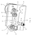
- Figure 1 shows a drive mechanism 10 for a windshield wiper.
- the drive mechanism provides an oscillating pivot for driving or moving a wiper arm through a wipe angle, the predetermined angular range for wiping a windshield.
- the mechanism shown has a single pivot for driving a single wiper arm and therefore, is particularly suited for use in trucks and buses or other large vehicles with independent wipers or for use with rear windows.
- the drive mechanism 10 comprises an electric motor 11 driving an output shaft 12 through a gearbox 13.
- the motor 11 and gearbox 13 are mounted on the back of a U-shaped bracket 14.
- An offset lever or crank 15 is fixed to the output shaft 12 for rotation therewith.
- the crank 15 drives a pivot 16 in an oscillating motion through a connecting link 17 and a lever 18.
- the effective lengths of the crank 15, link 17 and lever 18 determine the angular oscillations of the pivot 16.
- the connecting link 17 is pivotably connected to the crank 16 and lever 18 by drivers 19.
- the lever 18 is fixed to the pivot 16 for rotational movement therewith.
- the pivot 16 is supported by a bearing 20 which is mounted to the U-shaped bracket 14 which is used to mount the wiper mechanism to a vehicle for use therewith.
- the pivot 16 has a distal end 21 remote from the lever 18 to which the wiper arm is connected.
- the distal end 21 of the pivot has an internally threaded axial hole 22 for receiving a screw 23 for fixing the wiper arm thereto.
- the outer surface of the distal end 21 has a tapered knurled portion 24 forming a coupling surface dimensioned to mate with a DIN style mounting socket of a wiper arm.
- a ferrule 25 is provided for optional use to connect the pivot to a US style mounting socket of a wiper arm.
- the ferrule 25 has a through hole 26 with a tapered knurled inner surface (not shown) arranged to mate with the DIN style tapered knurled portion 24 of the pivot 16.
- the outer surface 27 of the ferrule 25 is tapered and knurled according to US style wiper requirements.
- the ferrule 25 is placed on the tapered portion 24 of the pivot 16 with the knurls meshed and a wiper arm with a US style mounting socket is placed onto the ferrule and the screw 23 placed through a hole in the wiper arm mount and the ferrule hole 26 and threadedly engages the hole 22 in the pivot 16.
- the screw 23 is tightened so that a flange 28 on the head of the screw bears down on the wiper arm mount and maintains the wiper arm fixedly secured to the pivot via the ferrule.
- Wiper arms with DIN style mounting sockets are fitted in a similar way directly to the tapered knurled portion 24 of the pivot 16 without the use of the ferrule 25.
- Use of the ferrule negates the need to manufacture and maintain separate wiper mechanisms for DIN style and US style wiper arms, thereby reducing inventory.
- the connecting link 17 is a generally elongated plate having a hole 29 at one end and two holes 30, 31 at the other end.
- Each hole has a plastic lining or grommet 32 providing a bearing interface between the connecting link 17 and the pivotable connection or driver 19 used to connect the connecting link 17 to the crank 15 and pivot lever 18.
- the distance between holes 29 and 30 is less than the distance between the holes 29 and 31.
- the grommets 32 may be molded directly to the link 17 in which case the grommets 32 for holes 30 and 31 may be integrally formed or joined together.
- the end of the connecting link with a single hole or first hole 29 is connected to the crank 15 via a first driver 19.
- the other end of the connecting link 17 is connected to the pivot 16 via a second driver 19 attached to the lever 18 and coupled to one of the two available holes 30, 31 of the link.
- the second and third holes 30, 31 are formed or located at predetermined distances from the first hole 29 such that the first and second predetermined distances are not equal.
- the first distance, the distance between the first hole 29 and the second hole 30 is 72 mm while the second predetermined distance, the distance between the first hole 29 and the third hole 31, is 81 mm, center to center.
- Coupling the driver 19 on the lever 18 to the second hole 30 or the third hole 31 changes the effective or operational length of the connecting link 17 which in turn changes the wipe angle, i.e., the angular distance that one turn of the crank 15 will cause the pivot 16 to move.
- this one connecting link 17 now can provide the function of two separate connecting links. While a connecting link with three holes can provide two desired wipe angles, connecting links with more than three holes are possible, such as four holes (two at each end) (four separate distances) or three holes at one end and one hole at the other end (three separate distances) could be used.
- the pivot lever 18 is provided with a number of holes 33 for mounting of the driver 19.
- the lever 18 has three separate driver mounting holes 33, each giving a different effective lever length (from pivot to driver), thus giving a different range of movement of the pivot when use with the second hole 30 or third hole 31 of the connecting link 17.
- three different effective lever lengths with two different effective connecting link lengths give six different wipe angles.
- these six wipe angles could be, say, 100°, 85°, 70°, 60°, 50°, 40°.
- the driver 19 has a part spherical portion 34 which mates with the plastic liner 32 of the connecting link 17 and a base portion 35 which spaces the spherical portion 34 away from the lever 18.
- the holes 29 in the lever 18 are hexagonal and receive a screw 36 with a hexagonal shank 37.
- the driver 19 also has a hexagonal hole 38 for receiving the screw 36.
- a nut 39 is threaded on the end of the screw 36 to fix the driver 19 to the lever 18.
- the driver may have an offset or eccentricism as illustrated by the eccentric drivers of the preferred embodiments where the hole through the driver is offset from the central axis of the part spherical portion 34.
- the driver 19 can be positioned in one of six different orientations. By careful selection of the offset direction and the orientation of the hexagonal mounting holes 29 in the lever 18, these six different orientations can give up to six different effective lever lengths or throws (distance from pivot center to driver center).
- the throw will be varied depending on driver orientation and the amount of offset.
- a total of 216 different combinations are possible affecting the wipe angle of the pivot.
- some combinations may result in duplicate wipe angles.
- a typical combination may give 54 unique wipe angles ranging from 41° to 108°.
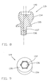
- Figures 8 and 9 illustrate an alternative offset or eccentric driver where the mounting hole and screw are replaced by an driver 119 with an integral shaft 136 which projects from the base portion 135 for mounting to the lever or crank.
- the shaft 136 engages a nut (not shown) to secure the driver 119 to the lever or crank and the shaft 136 has a hexagonal shank 137 for keying the driver 119 to the hexagonal holes in the lever or crank.
- a recess 140 is formed on the top of the driver 119 to form a reservoir for grease to lubricate the coupling.
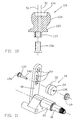
- Figure 10 shows a driver similar to the driver of Figures 8 and 9 except that the shank 137 has an internally threaded hole 141 and a separate screw 136 nips the driver 119 to the lever.
- FIGS 11 and 12 illustrate a driver 119 having a coaxial mounting hole 138 which receives a shaft portion of fixing screw 136.
- a nut 39 is screwed onto the shaft to fix the driver to the lever.
- the mounting screw has an integral shank 127 which mates in various orientations with the hole 29 in the lever 18 and the axis of the threaded screw portion is offset, i.e., non-coaxial with the axis of the shank portion.
- this offset mounting screw in the mounting hole of the lever produce variations in the mounting position of the body portion of the driver.
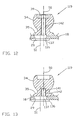
- Figure 13 illustrates a variation on the driver of Figure 12 in that the mounting screw 136 is screwed directly onto the base portion 35 of the driver 119.
- the mounting screw 136 is screwed directly onto the base portion 35 of the driver 119.
- the mounting axis 51 which is the axis of the shank 137 is laterally offset.
- Figure 14 illustrates a further variation over Figure 12 in that the shank 137 is a separate item from the screw and base portion.
- the shank 137 has a through hole for receiving a mounting screw 136 and is able to be fixed or keyed to the hole 29 in the lever 18 at a number of orientations.
- the hole in the shank is not co-axial with the mounting axis of the shank, as the shank is rotated with respect to the lever, the position of the hole rotates about the mounting axis, causing an offset effect in the location of the driver which is secured to the lever by the screw 136 passing through a through hole in the driver which is coaxial with the axis of symmetry 50 of the body portion 34 and a nut 79 nips the driver to the lever 18.
- Figure 15 is similar to the driver arrangement of Figure 14 with the nut 39 being replaced by an internally threaded hole 141 coaxial with the axis of symmetry 50.
- the screw could be replaced by a screw shaft integral with the base or body portions passing through the shank and engaging a nut to nip the driver to the lever.
- an acceptable wiper model may not be necessary for an acceptable wiper model to include all of the features of the preferred embodiment such as the extra hole in the connecting link and in the lever or maybe to provide extra holes in the crank instead.
- the driver or its mounting screw may have a shank which is not hexagonal in cross section, e.g. square giving up to four offset lengths or triangular giving up to only three offset lengths, etc.
Landscapes
- Engineering & Computer Science (AREA)
- Mechanical Engineering (AREA)
- General Engineering & Computer Science (AREA)
- Pivots And Pivotal Connections (AREA)
- Transmission Devices (AREA)
Abstract
Description
Claims (17)
- A driver for pivotable connection of linkage in a wiper mechanism, the driver (19) comprising:characterised in thata body portion (34) having a part spherical outer surface for mating with a bearing surface of a connecting linkage;a base portion (35) for locating the body portion (34) a predetermined distance from a lever (18) to which the driver (19) is mounted; andfixing means (36, 39) for fixing the driver (19) to the lever (18),
the fixing means allowing the driver (19) to be orientated with respect to the lever (18) whereby the effective length of the lever (18) is varied by varying the orientation of the driver (19). - The driver of claim 1 wherein the fixing means allows the driver (19) to be fixed to the lever at a desired orientation, said orientation being determined by rotation of the body portion about a mounting axis which is parallel to but spaced from an axis of symmetry of the body portion.
- The driver of claim 2 wherein the fixing means includes a shank (37, 137) and a hole (33) in the lever (18) through which the shank (37) extends.
- The driver of claim 3 wherein the hole (33) is non-circular and the shank (37) is non-circular and keyed to the hole (33).
- The driver of claim 4 wherein the shank (137) is integral with the base portion (135) and non-coaxial with an axis of symmetry of the body portion (134).
- The driver of claim 5 wherein the shank (137) has a threaded distal end (136) and the fixing means includes a nut (39) screwed onto the threaded distal end of the shank to fix the driver (19) to the lever (18).
- The driver of claim 5 wherein the shank (137) has an axially extending internally threaded hole (141) and the fixing means further includes a screw (136) threadedly engaged with the threaded hole (141) in the shank (137) to nip the driver (19) to the lever (18).
- The driver of claim 3 wherein the shank (37, 137) has a multi-sided geometric cross section.
- The driver of claim 3 wherein the shank (37, 137) is hexagonal.
- The driver of claim 3 wherein the hole (33) has a multi-sided geometric cross section.
- The driver of claim 3 wherein the hole (33) has the same geometric cross section as the shank (37, 137).
- The driver of claim 3 wherein the shank (37) is a part of a shaft of a screw (36), the shaft having a threaded free end; wherein the body portion (34) has a through hole (38) coaxial with the mounting axis and shaped to key with the shank (37) in a number of orientations and wherein a nut (39) is screwed onto the threaded free end of the shaft to nip the driver (19) to the lever (18).
- The driver of claim 3 wherein the fixing means includes a screw (136) and the shank (137) is a part of a shaft of the screw (136), the screw (136) has a threaded free end (142) having an axis (50) which is offset from an axis of the shank(51), the screw (136) being threadedly engaged with an internally threaded hole (141) in the base portion (135), said hole being coaxial with the axis of symmetry of the body portion (34).
- The driver of claim 3 wherein the fixing means includes a,screw (136) and the shank (137) is a part of a shaft of the screw (136), the screw (136) has a threaded free end (142) which is non-coaxial with the shank (137), the screw (136) passing through a hole in the body portion (34), said hole being coaxial with the axis of symmetry (50) of the body portion (34), and a nut (39) engaging the screw (136) nips the driver (19) to the lever (18).
- The driver of claim 3 wherein the fixing means includes a screw (136) threadedly engaged with a hole (141) in the base portion (35), said hole (141) being coaxial with the axis of symmetry (50) of the body portion (34), and the shank (137) is a separate spacer having an offset through hole accommodating the screw (136).
- The driver of claim 3 wherein the fixing means includes a screw passing through a hole in the base portion (35), said hole being coaxial with the axis of symmetry (50) of the body portion (34), and the shank (137) is a separate spacer having an offset through hole accommodating the screw (136).
- The driver of claim 1 when used in a wiper mechanism having a pivot lever (18) having more than one hole (33) for mounting the driver (19).
Applications Claiming Priority (2)
| Application Number | Priority Date | Filing Date | Title |
|---|---|---|---|
| US46373003P | 2003-04-18 | 2003-04-18 | |
| US463730P | 2003-04-18 |
Publications (2)
| Publication Number | Publication Date |
|---|---|
| EP1468886A2 true EP1468886A2 (en) | 2004-10-20 |
| EP1468886A3 EP1468886A3 (en) | 2005-03-23 |
Family
ID=32908758
Family Applications (1)
| Application Number | Title | Priority Date | Filing Date |
|---|---|---|---|
| EP04252194A Withdrawn EP1468886A3 (en) | 2003-04-18 | 2004-04-15 | Wiper mechanism |
Country Status (4)
| Country | Link |
|---|---|
| US (1) | US20040206202A1 (en) |
| EP (1) | EP1468886A3 (en) |
| JP (1) | JP2004314953A (en) |
| CN (1) | CN1537761A (en) |
Cited By (2)
| Publication number | Priority date | Publication date | Assignee | Title |
|---|---|---|---|---|
| FR2899188A1 (en) * | 2006-03-31 | 2007-10-05 | Valeo Systemes Dessuyage | Lock and windshield wiper motor module for motor vehicle, has lock and windshield wiper arm driving system`s swivel pin that are centered on longitudinal central axis of vehicle, and motor that is off centered with respect to axis |
| WO2011000594A1 (en) * | 2009-06-29 | 2011-01-06 | Robert Bosch Gmbh | Drive unit of a windshield wiper device in a vehicle |
Families Citing this family (10)
| Publication number | Priority date | Publication date | Assignee | Title |
|---|---|---|---|---|
| DE102004009717A1 (en) * | 2004-02-27 | 2005-09-15 | Robert Bosch Gmbh | Crankshaft arrangement and molded part for a crankshaft arrangement |
| DE102005062695A1 (en) * | 2005-12-28 | 2007-07-05 | Robert Bosch Gmbh | Method for adjusting the wiping angle in a wiper system with a reversing motor for a vehicle window |
| JP4884992B2 (en) * | 2007-01-25 | 2012-02-29 | 津田駒工業株式会社 | Drive amount change mechanism in crank drive |
| EP3388293B1 (en) * | 2017-04-14 | 2020-03-18 | Valeo Autosystemy SP. Z.O.O. | Movement transmission device for vehicle wiper device |
| FR3069519B1 (en) * | 2017-07-28 | 2019-08-16 | Valeo Systemes D'essuyage | FIXING DEVICE FOR WIPING ACTUATOR PIPING SYSTEM |
| US11131337B1 (en) | 2017-11-01 | 2021-09-28 | Northstar Manufacturing Co., Inc. | Adjustable ball joint |
| CN108045551A (en) * | 2017-11-22 | 2018-05-18 | 西安庆安电气控制有限责任公司 | A kind of rain brush resetting apparatus |
| FR3100504B1 (en) * | 2019-09-09 | 2022-04-15 | Valeo Systemes Dessuyage | Crankpin, ball joint and corresponding windshield wiper operating linkage system and method of assembling same |
| US11260903B2 (en) * | 2020-03-16 | 2022-03-01 | The Boeing Company | Variable linkage for tie-rods |
| US11845316B1 (en) | 2021-09-08 | 2023-12-19 | Northstar Manufacturing Co., Inc. | Adjustable pivot joint for vehicle suspensions |
Family Cites Families (12)
| Publication number | Priority date | Publication date | Assignee | Title |
|---|---|---|---|---|
| US215795A (en) * | 1879-05-27 | Improvement in pitman-connections and crank-pins | ||
| US2728244A (en) * | 1951-07-17 | 1955-12-27 | O'shei William Edward | Crank fittings |
| DE2036704A1 (en) * | 1970-07-24 | 1972-01-27 | Rau Swf Autozubehoer | Drive crank, in particular for the drive motor of a windshield wiper linkage |
| GB1449521A (en) * | 1974-02-20 | 1976-09-15 | Rolls Royce Motors Ltd | Transmission mechanism particularly for a windscreen wiper system |
| CA1015983A (en) * | 1974-08-28 | 1977-08-23 | Inco Limited | Double-eccentric variable drive system |
| DE2630067C2 (en) * | 1976-07-03 | 1985-06-05 | Robert Bosch Gmbh, 7000 Stuttgart | Wiper device for windows of motor vehicles |
| DE3738924A1 (en) * | 1987-11-17 | 1989-06-01 | Swf Auto Electric Gmbh | TRANSMISSION PART FOR A WIPING SYSTEM OF MOTOR VEHICLES AND METHOD FOR PRODUCING THE SAME |
| US5031265A (en) * | 1988-03-15 | 1991-07-16 | Asmo Co., Ltd. | Wiper device for wiping a vehicle windshield |
| US5556577A (en) * | 1992-06-03 | 1996-09-17 | Colgate-Palmolive Co. | High foaming nonionic surfactant based liquid detergent |
| DE4219480A1 (en) * | 1992-06-13 | 1993-12-23 | Swf Auto Electric Gmbh | Drive device for a windshield wiper for a motor vehicle |
| DE19746376A1 (en) * | 1997-10-21 | 1999-04-22 | Itt Mfg Enterprises Inc | Eccentric ball pin for windscreen wiper |
| US6131474A (en) * | 1997-11-06 | 2000-10-17 | Albany Magento Equipment, Inc. | Windshield wiper drive train |
-
2004
- 2004-04-14 JP JP2004118795A patent/JP2004314953A/en not_active Abandoned
- 2004-04-15 US US10/824,382 patent/US20040206202A1/en not_active Abandoned
- 2004-04-15 EP EP04252194A patent/EP1468886A3/en not_active Withdrawn
- 2004-04-16 CN CNA2004100368679A patent/CN1537761A/en active Pending
Cited By (4)
| Publication number | Priority date | Publication date | Assignee | Title |
|---|---|---|---|---|
| FR2899188A1 (en) * | 2006-03-31 | 2007-10-05 | Valeo Systemes Dessuyage | Lock and windshield wiper motor module for motor vehicle, has lock and windshield wiper arm driving system`s swivel pin that are centered on longitudinal central axis of vehicle, and motor that is off centered with respect to axis |
| WO2011000594A1 (en) * | 2009-06-29 | 2011-01-06 | Robert Bosch Gmbh | Drive unit of a windshield wiper device in a vehicle |
| CN102470825A (en) * | 2009-06-29 | 2012-05-23 | 罗伯特·博世有限公司 | Drive unit of a windshield wiper device in a vehicle |
| CN102470825B (en) * | 2009-06-29 | 2015-08-19 | 罗伯特·博世有限公司 | The driver element of the windshield wiper in vehicle |
Also Published As
| Publication number | Publication date |
|---|---|
| JP2004314953A (en) | 2004-11-11 |
| EP1468886A3 (en) | 2005-03-23 |
| US20040206202A1 (en) | 2004-10-21 |
| CN1537761A (en) | 2004-10-20 |
Similar Documents
| Publication | Publication Date | Title |
|---|---|---|
| EP1468886A2 (en) | Wiper mechanism | |
| EP1468885B1 (en) | Wiper mechanism | |
| US8359702B2 (en) | Ball and socket joint utilizing a single ball, for driving more than one driven member | |
| JP4325403B2 (en) | Electric steering column device | |
| US5473955A (en) | Wiper system double ball joint | |
| KR100563497B1 (en) | Mirror driving device | |
| EP1266810B1 (en) | Wiper apparatus for motor vehicle | |
| EP0904983A2 (en) | Wiper for a vehicular mirror | |
| JPH0132603Y2 (en) | ||
| US20040205923A1 (en) | Wiper mechanism | |
| US7610649B2 (en) | Wiper device | |
| JP2002539999A (en) | Wiper drive with reversible geared motor | |
| US20140250622A1 (en) | Windshield wiper assembly | |
| KR200200223Y1 (en) | Wiper linkage assembly for use in an automobile | |
| JP3516046B2 (en) | Vehicle wiper pivot device | |
| CA1258186A (en) | Windshield wiper ball joint | |
| JP4038313B2 (en) | Wiper device | |
| JP4009400B2 (en) | Wiper pivot and wiper device | |
| CN111661131B (en) | Automatic return electronic steering wheel | |
| CN220682568U (en) | Motorcycle pedal adjustment components | |
| JP3859395B2 (en) | Wiper unit | |
| JP3586132B2 (en) | Pantograph wiper | |
| JP3515984B2 (en) | Wiper link device | |
| KR20240174394A (en) | Connection device for attaching a bicycle and a sidecar | |
| JPH08133021A (en) | Wiper device for vehicle |
Legal Events
| Date | Code | Title | Description |
|---|---|---|---|
| PUAI | Public reference made under article 153(3) epc to a published international application that has entered the european phase |
Free format text: ORIGINAL CODE: 0009012 |
|
| AK | Designated contracting states |
Kind code of ref document: A2 Designated state(s): AT BE BG CH CY CZ DE DK EE ES FI FR GB GR HU IE IT LI LU MC NL PL PT RO SE SI SK TR |
|
| AX | Request for extension of the european patent |
Extension state: AL HR LT LV MK |
|
| PUAL | Search report despatched |
Free format text: ORIGINAL CODE: 0009013 |
|
| AK | Designated contracting states |
Kind code of ref document: A3 Designated state(s): AT BE BG CH CY CZ DE DK EE ES FI FR GB GR HU IE IT LI LU MC NL PL PT RO SE SI SK TR |
|
| AX | Request for extension of the european patent |
Extension state: AL HR LT LV MK |
|
| 17P | Request for examination filed |
Effective date: 20050808 |
|
| AKX | Designation fees paid |
Designated state(s): AT BE BG CH CY CZ DE DK EE ES FI FR GB GR HU IE IT LI LU MC NL PL PT RO SE SI SK TR |
|
| STAA | Information on the status of an ep patent application or granted ep patent |
Free format text: STATUS: THE APPLICATION IS DEEMED TO BE WITHDRAWN |
|
| 18D | Application deemed to be withdrawn |
Effective date: 20060613 |