EP1468639A2 - Improved mop assembly with liquid detergent supply - Google Patents
Improved mop assembly with liquid detergent supply Download PDFInfo
- Publication number
- EP1468639A2 EP1468639A2 EP04008737A EP04008737A EP1468639A2 EP 1468639 A2 EP1468639 A2 EP 1468639A2 EP 04008737 A EP04008737 A EP 04008737A EP 04008737 A EP04008737 A EP 04008737A EP 1468639 A2 EP1468639 A2 EP 1468639A2
- Authority
- EP
- European Patent Office
- Prior art keywords
- pipe
- liquid detergent
- pump
- storage bottle
- disposed
- Prior art date
- Legal status (The legal status is an assumption and is not a legal conclusion. Google has not performed a legal analysis and makes no representation as to the accuracy of the status listed.)
- Withdrawn
Links
Images


Classifications
-
- A—HUMAN NECESSITIES
- A47—FURNITURE; DOMESTIC ARTICLES OR APPLIANCES; COFFEE MILLS; SPICE MILLS; SUCTION CLEANERS IN GENERAL
- A47L—DOMESTIC WASHING OR CLEANING; SUCTION CLEANERS IN GENERAL
- A47L13/00—Implements for cleaning floors, carpets, furniture, walls, or wall coverings
- A47L13/10—Scrubbing; Scouring; Cleaning; Polishing
- A47L13/20—Mops
- A47L13/22—Mops with liquid-feeding devices
-
- A—HUMAN NECESSITIES
- A47—FURNITURE; DOMESTIC ARTICLES OR APPLIANCES; COFFEE MILLS; SPICE MILLS; SUCTION CLEANERS IN GENERAL
- A47L—DOMESTIC WASHING OR CLEANING; SUCTION CLEANERS IN GENERAL
- A47L13/00—Implements for cleaning floors, carpets, furniture, walls, or wall coverings
- A47L13/10—Scrubbing; Scouring; Cleaning; Polishing
- A47L13/20—Mops
- A47L13/24—Frames for mops; Mop heads
- A47L13/254—Plate frames
- A47L13/258—Plate frames of adjustable or foldable type
Definitions
- the present invention relates to an improved mop assembly with liquid detergent supply, comprising a detachable storage bottle, a detachable handle, and a detachable mop that constitute a linear body after assembling the foregoing components.
- a detachable storage bottle By means of the reciprocating movement of the handle, the pump in the storage bottle is squeezed to convey the detergent for convenient use, and the present invention can reduce the packaging volume for transportation and lower the cost.
- a contractible support rod is disposed on each on both sides of the mop to fit the mops of different specifications and thus enhancing the cost-effectiveness of such technical area.
- a mop is a common cleaning tool that has existed for a long time. It is generally used together with a piece of cotton cloth or a polyester cloth to offer convenience of cleaning highly recognized by consumers.
- liquids such as clean water or liquid detergent
- the primary objective of the present invention is to solve the foregoing problems by taking the following measures.
- the present invention can achieve the following effects:
- a mop 1 comprises a connecting pipe 12 pivotally coupled to a pivotal connector 11; a screw pipe 21 extended from the bottom of a storage bottle 2; a pivotal groove 22 disposed in the front end, wherein a flow hole being disposed at its center; a leak-proof spacer 23 surrounding the flow hole 221, and said pivotal groove 22 at its end opening having four flanges 222; an outlet nozzle 224 (refer to FIG.
- a fixed bottle cover 25 is secured onto another end of the storage bottle and a washer 251 is used to prevent leakage, and an inject hole 25 is disposed at an appropriate position of the fixed bottle cover 25 and sealed by a stopper 253 to facilitate the fill-up of liquid detergent; and an axial hole 254 is disposed at the top of said fixed bottle cover 25, and an O-shape ring 2542 is disposed on the hole edge 2541 at the bottom of the axial hole 254, and a radial fixing serration 255 is disposed on the surface of said central hole 2541; a push member 26 is disposed at the bottom of said fixing serration 255 having a sleeve 261 at one end, and a radial latch serration 262 is disposed at a position of said serration 255 corresponsive to the surface of the push member
- the curved pipe 3 is connected to a suction pipe 32 extending into a storage bottle 2, and a sphere stopper is placed in a pump 4 at the position where such suction pipe 32 and its passage 33 are connected; a pump 4 having a sphere stopper 41 at its top is supported by a compressed spring 42 to press against the front end of a passage opening 411, and said compressed spring presses against a sealing stopper 43, and one end of said sealing blocking stopper is plugged into a piston 44 and a relay push pipe 45 presses against the bottom of said sealing stopper 43, while said relay push pipe 45 covers the lower end of said relay push pipe by a main push pipe 46, and the front end of the blocking edge 461 of the main push pipe 46 is sleeved from a main push pipe 45 by a bottle stopper 49 and embedded into the bottom of the pump 4 such that the bottle stopper 49 supports said piston 44 and the blocking edge 461 of the main push pipe 46 while keeping an appropriate distance between the piston 44 and the blocking edge 461 of the main push pipe 46 and pressing
- the lower end of the main push pipe 46 is embedded into the fixed hole 223 at the bottom of the storage bottle 2 and the outer periphery of the main push pipe 46 has a secondary spring 47 being supported between the bottom of the pump 4 and the bottom of the storage bottle 4, so that the handle connecting pipe A, push member 26, bump 4, main push pipe 46, connecting pipe 12, and mop 1 form a longitudinal line vertical to a central line, and the relay push pipe 45, main push pipe 46, fixed hole 223, flow hole 221, and the nozzle opening 242 of the outlet nozzle 24 constitute a liquid detergent passage.
- the aforementioned structure can extend the third embodiment of this invention; please see Fig.15, Fig.16, Fig.17 and Fig.18-A.
- the handle connecting pipe A is set between the aforementioned limit axle bolt 27 and is tightened with the stud R.
- the handle 7, which consists of two half-shape handles 71, 72 is fastened at the end of the handle connecting pipe A with a pivot 73 inside the handle.
- the handle 7 is fastened at the other end of the handle connecting pipe A.
- a pivot hole 741 is disposed in the appropriate position.
- the butting part 742 is set at the end of the pivot hole 741, and at the other end, the triggering part 743 is disposed.
- the pivot hole 741 of the trigger 74 is set between the two half-shape handles 71, 72 with the pivot 73 piercing and set in the hole, by the high frequency or other measures (like locking), the trigger 74 can lever wit pivot 73 as an axle center.
- a control rod A1 is disposed inside the handle connecting pipe A.
- Fig.18-A, B When the triggering part 743 of the trigger 74 is triggered, the butting part 742 would butt the control rod A1 and relatively butt the push member 6 and then squeeze pump 4. The liquid detergent would be squeezed out form inside the pump 4 and from the spray nozzle 24, and a spray of detergent would spurt out.
- the control rod A1 When the auxiliary spring 47 and the squeezed spring 42 together with the pump 4 return to its normal state, the control rod A1 would relatively butt the triggering part 742 of the trigger 74; at the same time, the suction pipe 3 also takes in detergent W and the detergent would be stored in the pump to prepare for next trigger and do the action as what has mentioned above again.
- the mop 1 offers the function of cleaning any places and comers easily and conveniently and offers the other function of watering plants; the new invention would reach all-direction effect.
Landscapes
- Cleaning Implements For Floors, Carpets, Furniture, Walls, And The Like (AREA)
Abstract
Description
- 1.The present invention relates to an improved mop assembly with liquid detergent supply, comprising a detachable storage bottle, a detachable handle, and a detachable mop that constitute a linear body after assembling the foregoing components. By means of the reciprocating movement of the handle, the pump in the storage bottle is squeezed to convey the detergent for convenient use, and the present invention can reduce the packaging volume for transportation and lower the cost. Additionally, a contractible support rod is disposed on each on both sides of the mop to fit the mops of different specifications and thus enhancing the cost-effectiveness of such technical area.
- 2.A mop is a common cleaning tool that has existed for a long time. It is generally used together with a piece of cotton cloth or a polyester cloth to offer convenience of cleaning highly recognized by consumers. However, when a user needs to remove dirt by liquids such as clean water or liquid detergent, it is necessary to spray the dirty place first and wipe off the dirt by a mop, and thus causing inconvenience to users for such operation. Therefore, the following prior arts came to their place:
- (1) The first prior art hangs a storage bottle on the handle of a mop and installs a small direct current pump outside the storage bottle; a press switch is disposed at the top of the handle; an electric cable extends along the exterior of a pipe of the sectional handle to such small electric pump for supplying power from a battery outside the storage bottle; and by means of pressing the switch, the electric pump is controlled to spray liquid detergent from the storage bottle.
- (2) The second prior art also sets a press switch at the top of the handle of a mop, and uses the siphon principle of an air pump as well as extends the pipeline from the interior of the pipe of the handle into a storage bottle. By pressing the switch, the air pump is controlled to spray the liquid detergent.
-
- The aforementioned first prior art still has the following shortcomings:
- (1) The storage bottle is hung outside the handle of the mop. Since the storage bottle protrudes from the outer side, and liquid detergent is stored in the storage bottle when the mop is being used, the center of gravity deviates from the mop, which causes an unstable operation of the mop.
- (2) Battery is used as power supply to the electric pump, and the power consumption is large. It is necessary to replace the battery quite often, and causes inconvenience to its use. The storage bottle is dipped or wetted by the liquid detergent easily, and causes corrosions and damages to the battery and the battery compartment.
- (3) The electric cable is installed in the pipe of a sectional handle, which makes the assembling procedure complicated and increases costs. In addition, when the mops are packed separately, the volume is larger and thus increasing the volume of material for transportation as well as the transportation cost.
- (4) The electric cable installed in the pipe of the sectional handle has a specific length, so that the length of the handle cannot be adjusted according to the height of the user, which limits its use.
- (5) The foregoing mop is of a fixed specification, and cannot be used together with a longer piece of cloth for the mops of other specifications.
-
- The aforementioned second prior art still has the following shortcomings:
- (1) Since the press switch is installed at the top of the handle, and there is a pipeline inside the pipe of the sectional handle. To detach the sections of the handle, a pipe connector is needed at each end of the joint for the connection of the sections of the handle. Air leakage may occur and make the operation impossible if such joint is loosened during the assembling or while the mop is in use.
- (2) The assembling procedure of the aforementioned handle is complicated, and thus increasing the cost.
- (3) The foregoing storage bottle is hung outside the front of the handle of the mop. Since the storage bottle stores liquid detergent and its center of gravity deviates from the mop, causing an unstable operation.
- (4) Since the pipeline is too long, it is difficult for the air pump to provide a fixed quantity of the sprayed liquid detergent. It is necessary to press the press switch many times to spray the required amount of detergent, and thus making the use time-consuming and a waste of efforts.
- (5) The foregoing mop is also of fixed specification, and cannot be used together with a longer piece of cloth of other specifications.
-
- The primary objective of the present invention is to solve the foregoing problems by taking the following measures.
- (1) The present invention directly connects a storage bottle with a sectional handle and a mop, such that the center of gravity of the storage bottle falls onto the mop, and makes the operation stable for users, and can reduce the volume of material for individual packaging and lower the transportation cost.
- (2) A pump is installed inside the storage bottle, and the back-and-forth pressing movement drives the handle to squeeze the pump in a longitudinal direction, and the compression is larger than that of the aforementioned electric pump, so that the liquid detergent can be spread out and sprayed evenly.
- (3) There is no pipeline or electric cable inside the pipe of the sectional pipe in accordance with the present invention, which makes the assembly easy and saves assembling costs. In addition, the length of the sectional handle can be adjusted according to the height of the user, which flexibly expands the effect of its applications.
- (4) The mop of the present invention has a contractible support rod at the interior of both sides to provide the extension of the mop's length and fit the cloths of different specifications.
- (5) In this invention, a control rod bottle is set in the handle connecting pipe. And one end of the handle connecting pipe is fastened to the abovementioned limit axle bolt of the fixed bottle cover. The fixation makes the two ends of the control rod, which is within the handle connecting pipe, respectively butt the top of the pump and the butting part of the trigger. The butting part of the trigger can do the push directly to the control rod and relatively squeeze the pump. So, through the restoration of the squeezed auxiliary spring under the pump and the restoration of the squeezed spring inside the pump, it is liable to reach the effect upon controlling the spray of liquid cleaner.
- (6) The suction pipe set in the pump as mentioned above adopts the suction of the material of soft quality and the material with weight, so it can totally set inside the cleaner to offer all-direction effects no matter how the storage bottle angles.
-
- Therefore, the present invention can achieve the following effects:
- (1) The present invention makes the assembling easy, saves costs, reduces the volume of material after packaging individually, and lowers the transportation cost.
- (2) The present invention is easy to operate, and gives a larger quantity of sprayed liquid detergent.
- (3) The present invention provides a stable operation for users without the phenomenon of deviated center of gravity.
- (4) There is no pipeline or electric cable inside the sectional handle, and the length of the handle can be adjusted according to the height of the user.
- (5) According to the third embodiment, to raise the effect, our invention offers the function of spraying cleaner in various comers and places.
- (6) The mop of the present invention allows contractible adjustments to fit the cloths of different specifications and thus expanding the effect of its applications.
-
- Other features and advantages of the present invention will become apparent in the following detailed description of the preferred embodiments with reference to the accompanying drawings, in which:
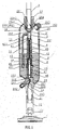
- FIG.1 is a cross-sectional diagram of the assembled structure of the present invention.
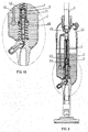
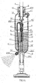
- FIG.2 is a perspective cross-sectional diagram of the fixed bottle cover of the present invention.
- FIG.3 is a perspective diagram of the disassembled parts of the outlet nozzle and storage bottle of the present invention.
- FIG.4 is a cross-sectional diagram illustrating the first step of the movement according to a preferred embodiment of the present invention.
- FIG.4A is an enlargement of a part of FIG. 4.
- FIG. 5 is a cross-sectional diagram illustrating the second and fourth steps of the movement according to a preferred embodiment of the present invention.
- FIG.5A is an enlargement of a part of FIG. 5.
- FIG.6 is a cross-sectional diagram illustrating the third step of the movement according to a preferred embodiment of the present invention.
- FIG.6A is an enlargement of a part of FIG. 6.
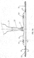
- FIG.7 is an illustrative diagram of the present invention when it is in use.
- FIG.8 is a cross-sectional diagram showing the operation of the outlet nozzle according to the present invention.
- FIG.9 is a cross-sectional diagram of the assembled parts according to a second preferred embodiment of the present invention.
- FIG. 10 is a cross-sectional diagram illustrating the first step of the movement according to a second preferred embodiment of the present invention.
- FIG.11 is a cross-sectional diagram illustrating the second step of the movement according to a second preferred embodiment of the present invention.
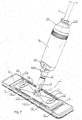
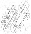
- FIG. 12 is a perspective diagram of the disassembled parts of the mop according to the present invention.
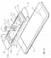
- FIG.13 is a perspective diagram of the assembled parts of the mop according to the present invention.
- FIG.13A is a planar illustrative diagram of the mop according to a preferred embodiment of the present invention.
- FIG. 14 is a perspective diagram of the mop according to another preferred embodiment of the present invention.
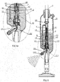
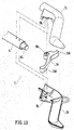
- FIG 15 is a perspective diagram of the allocation of the disassembled parts according to the third embodiment of the present invention.
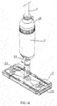
- FIG 16 is a perspective diagram of the assembled parts of the handle according to the third embodiment of the present invention.
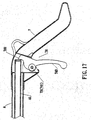
- FIG 17 is a cross-sectional diagram of the assembled parts according to the third embodiment of the present invention.
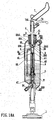
- FIG18A is a cross-sectional diagram of the assembled parts according to the third embodiment of the present invention.
- FIG18B is a cross-sectional diagram of the assembled parts according to the third embodiment of the present invention.
-
- To make it easier for our examiner to understand the objective of the invention, its structure, innovative features, and performance, we use two preferred embodiments together with the attached drawings for the detailed description of the invention.
- Please refer to FIGs. 1, and 2 for the first preferred embodiment. In the figure, a
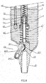
mop 1 comprises a connectingpipe 12 pivotally coupled to apivotal connector 11; ascrew pipe 21 extended from the bottom of astorage bottle 2; apivotal groove 22 disposed in the front end, wherein a flow hole being disposed at its center; a leak-proof spacer 23 surrounding theflow hole 221, and saidpivotal groove 22 at its end opening having fourflanges 222; an outlet nozzle 224 (refer to FIG. 3) having an arcedrotary head 241 at one end and aspray nozzle 24 at the other end, through which anoutlet passage 243 passes; saidrotary head 241 is embedded and protruded from saidflanges 222 into saidpivotal groove 22 such that the flange just exceeds the diameter of saidrotary head 241 and theoutlet passage 243 in therotary head 241 connects to saidflow hole 221 under normal conditions. When saidoutlet nozzle 24 is moved vertically such that theoutlet passage 243 separates from theflow hole 221 and blocks the liquid detergent by a leak-proof spacer 23 to stop the supply or leakage of liquid detergent; further, a fixedbottle cover 25 is secured onto another end of the storage bottle and awasher 251 is used to prevent leakage, and an injecthole 25 is disposed at an appropriate position of the fixedbottle cover 25 and sealed by astopper 253 to facilitate the fill-up of liquid detergent; and anaxial hole 254 is disposed at the top of said fixedbottle cover 25, and an O-shape ring 2542 is disposed on thehole edge 2541 at the bottom of theaxial hole 254, and aradial fixing serration 255 is disposed on the surface of saidcentral hole 2541; apush member 26 is disposed at the bottom of said fixingserration 255 having asleeve 261 at one end, and aradial latch serration 262 is disposed at a position of saidserration 255 corresponsive to the surface of thepush member 26, and a limit member is extended from the bottom of thepush member 26. When thesleeve 261 of saidpush member 26 is sheathed and secured onto the handle connecting pipe A and passes through thecentral hole 25 of saidaxial hole 254, the pipe wall of the handle connecting pipe A exactly presses against said O-shape ring 2542 and is secured into saidaxial hole 254 by alimit axle bolt 27 to limit the positions of the O-shapedring 2542 and the handle connecting pipe A. In the meantime, thelatch serration 262 of saidpush member 26 is engaged with the fixingserration 255 on the surface of saidcentral hole 2541, and thelimit member 26 at the bottom of saidpush member 26 is embedded into alimit groove 31 at the top of thecurved pipe 3. Thecurved pipe 3 is connected to asuction pipe 32 extending into astorage bottle 2, and a sphere stopper is placed in apump 4 at the position wheresuch suction pipe 32 and itspassage 33 are connected; apump 4 having asphere stopper 41 at its top is supported by acompressed spring 42 to press against the front end of apassage opening 411, and said compressed spring presses against a sealingstopper 43, and one end of said sealing blocking stopper is plugged into apiston 44 and arelay push pipe 45 presses against the bottom of said sealingstopper 43, while saidrelay push pipe 45 covers the lower end of said relay push pipe by amain push pipe 46, and the front end of the blockingedge 461 of themain push pipe 46 is sleeved from amain push pipe 45 by a bottle stopper 49 and embedded into the bottom of thepump 4 such that the bottle stopper 49 supports saidpiston 44 and the blockingedge 461 of themain push pipe 46 while keeping an appropriate distance between thepiston 44 and the blockingedge 461 of themain push pipe 46 and pressing against the blockingedge 461 of themain push pipe 46 to prevent themain push pipe 46 from falling out. In the meantime, the lower end of themain push pipe 46 is embedded into the fixedhole 223 at the bottom of thestorage bottle 2 and the outer periphery of themain push pipe 46 has asecondary spring 47 being supported between the bottom of thepump 4 and the bottom of thestorage bottle 4, so that the handle connecting pipe A,push member 26,bump 4,main push pipe 46, connectingpipe 12, andmop 1 form a longitudinal line vertical to a central line, and therelay push pipe 45,main push pipe 46,fixed hole 223,flow hole 221, and thenozzle opening 242 of theoutlet nozzle 24 constitute a liquid detergent passage. - Please refer to FIG. 1. Before the mop according to the present invention is used, inject the liquid detergent into the
storage bottle 2 through the injecthole 252 and seal the bottle with astopper 253, and follow the procedure as follows: - (1) Adjust the handle connecting pipe A according to the user's height or
requirements and secure it to the sectional handle. To prevent the
bump 4 in thestorage bottle 2 from being rotated when securing the handle, use the upward pushing force of thecompressed spring 42 in thebump 4 and thesecondary spring 47 at lower end of the bump to prop thepush member 26 towards the surface of thecentral hole 2541 at the top of the interior of thestorage bottle 2, and engage thelatch serration 262 on thepush member 262 and the fixedserration 255 on the surface of thecentral hole 2541 such that the fixedpush member 26 and the handle connecting pipe A will not rotate as the sectional handle is being secured. - (2) Please refer to FIGS. 4 and 4A. Before the mop of the present invention has ever
been used, there is no liquid detergent W in the
bump 4. When the handle A erects thestorage bottle 2 to a vertical position, the handle is in the most power saving condition for compressing thebump 4, therefore when the handle connecting pipe A compresses thepush member 26, thebump 4 sinks and themain push pipe 46 relatively enters into thebump 4 while pushing the sealingstopper 43 up and separating thepiston 44 and leaving a gap B behind. Please refer to FIGS. 5 and 5A. Therelay push pipe 45 keeps on being pushed forward by themain push pipe 46 and the blockingedge 461 of themain push pipe 46 in turn pushes thepiston 44 to squeeze the air in the squeezingchamber 48 in thebump 4. Thesphere stopper 41 squeezed by the air pressure on one hand, and pushed by thecompressed spring 42 on the other hand clogs thepassage opening 411. The air is compressed by thepiston 44, and enters through the gap B into therelay push pipe 45,main push pipe 46,flow hole 221, and nozzle opening 242 ofoutlet nozzle 24, and then discharge the air. - (3) Please refer to FIGS. 6 and 6A. If the user no longer pushes the handle A, then
the resuming forces of the
compressed spring 42 in thebump 4 and thesecondary spring 47 are used to push thebump 4 upward, while thepiston 44 uses the friction of the inner wall of thebump 4 to keep thepiston 44 still in the original position. The sealingstopper 43 drops to the position of thepiston 44 and clog the gap B. At that time, since thebump 4 rises, it is equivalent to the drop of thepiston 44 to extract the air in the squeezingchamber 48 of thebump 4 such that thesphere stopper 41 is separated from thepassage opening 411 by the suction and forms a gap B. Such suction sucks the liquid detergent W by thesuction pipe 32 through thecurved pipe 3,passage 33, passage opening 411, gap B' and then into the squeezingchamber 48 of thebump 4 for temporary storage. - (4) The liquid detergent W temporarily stored in the squeezing
chamber 48 is blocked by the sealing between the sealingstopper 43 and thepiston 44, and squeezed by thepiston 44 according to the previous step (2), which is also shown in FIGS. 5 and 5A. The liquid detergent is squeezed into therelay push pipe 45 through the gap B between the sealingstopper 43 and thepiston 44, and then sprayed out through themain push pipe 46,flow hole 221, and nozzle opening 242 of theoutlet nozzle 24. - (5) In the foregoing step, the back and forth movement of the handle can squeeze and
resume the
bump 4 to spray the required quantity of the liquid detergent. - (7) The handle is usually set to an appropriate angle to use the mop (as shown in
FIG. 7), and the
mop 1 is placed in front of the user to facilitate the movement of the mop. Therefore the force exerting on thebump 4 produced by the inclination of the handle plus the resisting forces by thecompressed spring 42 and thesecondary spring 47 will not sufficient to squeeze thebump 4 when a pushing force is applied onto the mop when it is in use. - (8) Please refer to FIG. 8. To prevent the mop of the present invention from
dripping the liquid detergent remained in the nozzle opening or spraying the
detergent by accidentally trigger the handle to squeeze the
bump 4, theoutlet nozzle 24 can be lifted upward to detach theoutlet passage 243 from the flow hole 211 and seal by theanti-leakage spacer 23 to prevent further spray of liquid detergent.
Please refer to FIG. 9 for the second preferred embodiment of the present invention.
In the figure, the pump 4' has a structure identical to the -
- The operation procedure is as follows:
- (1) Please refer to FIG. 10. If the handle connecting pipe A pushes the push
member 62 to sink the main push pipe 46', and the
main push pipe 46 relatively enters into the bump 4', while pressing the sealingstopper 43 down, and separating thepiston 44 to form a gap B between them. Please refer to FIG. 11. Saidrelay push pipe 45 keeps on being pushed forward by the main push pipe 46', and the blockingedge 461 pushes thepiston 44 to squeeze the liquid detergent W in the squeezingchamber 48 of the bump 4'. Thesphere stopper 41 is pressed by the pressure on one hand, and pushed by thecompressed spring 42 on the other hand to block the passage opening 411'. Therefore, the liquid detergent W is compressed by thepiston 4 to enter into said gap B and then into therelay push pipe 45,main push pipe 46, conveying pipe D, the outlet passage 243' of the outlet nozzle 24', and then discharged from the nozzle 242'. - (2) If the user no longer pushes the handle A, but resumes the movement as
shown in FIG. 11 to the movement as shown in FIG. 9. Therefore, the
resuming force by the
compressed spring 42 and the secondary spring 47' in the bump 4' is used to push the main push pipe 46' up, while thepistons 44 uses the friction on the inner wall of the bump 4' to drop thepiston 44 to the position of the sealingstopper 43 and blocks the gap B. At that time, since the main push pipe 46' rises, it relatively makes the piston to pump the liquid detergent W in the squeezingchamber 48 of the bump 4' and separates thesphere stopper 41 from the passage opening 411' by said suction to form a gap. Such suction sucks the liquid detergent W through thesuction opening 321 and the suction pipe 32' and the gap B' into the squeezingchamber 48 of the bump 4' for temporary storage. - (3) The required quantity of liquid detergent can be sprayed by the back and forth squeezing and resuming movement of the handle on the bump 4' as described in the previous step. Please refer to FIGS. 12 and 13. The
-
- The aforementioned structure can extend the third embodiment of this invention; please see Fig.15, Fig.16, Fig.17 and Fig.18-A. The handle connecting pipe A is set between the aforementioned
limit axle bolt 27 and is tightened with the stud R. And thehandle 7, which consists of two half-shape handles 71, 72, is fastened at the end of the handle connecting pipe A with apivot 73 inside the handle. And, with thepivot 73 inside thehandle 7, which consists of two half-shape handles71, 72, thehandle 7 is fastened at the other end of the handle connecting pipe A. In the middle of thetrigger 74, apivot hole 741 is disposed in the appropriate position. The buttingpart 742 is set at the end of thepivot hole 741, and at the other end, the triggeringpart 743 is disposed. As thepivot hole 741 of thetrigger 74 is set between the two half-shape handles 71, 72 with thepivot 73 piercing and set in the hole, by the high frequency or other measures (like locking), thetrigger 74 can leverwit pivot 73 as an axle center. A control rod A1 is disposed inside the handle connecting pipe A. One of its ends is fastened into theaforementioned push member 26; (the measures of the fixation of the control rod A1 can be the direct insertion into thesleeve 261 of thepush member 26 without the screw S or the insertion with the screw S) and the other end lies against the buttingpart 742 of thetrigger 74. - Please see Fig.18-A, B: When the triggering
part 743 of thetrigger 74 is triggered, the buttingpart 742 would butt the control rod A1 and relatively butt the push member 6 and then squeezepump 4. The liquid detergent would be squeezed out form inside thepump 4 and from thespray nozzle 24, and a spray of detergent would spurt out. When theauxiliary spring 47 and the squeezedspring 42 together with thepump 4 return to its normal state, the control rod A1 would relatively butt the triggeringpart 742 of thetrigger 74; at the same time, thesuction pipe 3 also takes in detergent W and the detergent would be stored in the pump to prepare for next trigger and do the action as what has mentioned above again. - Therefore, the
mop 1 offers the function of cleaning any places and comers easily and conveniently and offers the other function of watering plants; the new invention would reach all-direction effect. - While the invention has been described by way of example and in terms of a preferred embodiment, it is to be understood that the invention is not limited thereto. To the contrary, it is intended to cover various modifications and similar arrangements and procedures, and the scope of the appended claims therefore should be accorded the broadest interpretation so as to encompass all such modifications and similar arrangements and procedures.
Claims (14)
a board surface, and said mop being used with a piece of cleaning cloth or polyester cloth of the same specification, characterized in that:
Applications Claiming Priority (2)
| Application Number | Priority Date | Filing Date | Title |
|---|---|---|---|
| US10/412,212 US6692172B1 (en) | 2003-04-14 | 2003-04-14 | Mop assembly with liquid detergent supply |
| US412212 | 2003-04-14 |
Publications (2)
| Publication Number | Publication Date |
|---|---|
| EP1468639A2 true EP1468639A2 (en) | 2004-10-20 |
| EP1468639A3 EP1468639A3 (en) | 2008-06-18 |
Family
ID=32908281
Family Applications (1)
| Application Number | Title | Priority Date | Filing Date |
|---|---|---|---|
| EP04008737A Withdrawn EP1468639A3 (en) | 2003-04-14 | 2004-04-13 | Improved mop assembly with liquid detergent supply |
Country Status (1)
| Country | Link |
|---|---|
| EP (1) | EP1468639A3 (en) |
Cited By (5)
| Publication number | Priority date | Publication date | Assignee | Title |
|---|---|---|---|---|
| CN106361225A (en) * | 2016-08-29 | 2017-02-01 | 李汉文 | Medical rotation type efficient ward ground cleaning device |
| CN106419779A (en) * | 2016-08-31 | 2017-02-22 | 嘉兴捷顺旅游制品有限公司 | Separating spray mob |
| CN107049171A (en) * | 2017-04-27 | 2017-08-18 | 包丰阁 | A kind of watering mop certainly |
| CN109208267A (en) * | 2018-10-22 | 2019-01-15 | 慈溪市顺达实业有限公司 | A kind of automatic adding device of detachable replaceable container |
| CN117225662A (en) * | 2023-07-30 | 2023-12-15 | 华能伊敏煤电有限责任公司 | Desulfurization circulating pump impeller repairing method and equipment |
Citations (5)
| Publication number | Priority date | Publication date | Assignee | Title |
|---|---|---|---|---|
| WO1998023385A1 (en) * | 1996-11-26 | 1998-06-04 | The Procter & Gamble Company | Decoupled liquid delivery system |
| WO1998023200A1 (en) * | 1996-11-26 | 1998-06-04 | The Procter & Gamble Company | Cleaning implement having a sprayer nozzle attached to a cleaning head member |
| US20010006588A1 (en) * | 1999-12-30 | 2001-07-05 | A.Z. International S.A. | Broom provided with a regulator for controlling the flow of floor cleaning and treatment products |
| WO2001072195A1 (en) * | 2000-03-24 | 2001-10-04 | The Clorox Company | Advanced cleaning system |
| US20030053845A1 (en) * | 2001-09-14 | 2003-03-20 | Dale Aberegg | Cleaning device with a trigger-actuated spray canister |
-
2004
- 2004-04-13 EP EP04008737A patent/EP1468639A3/en not_active Withdrawn
Patent Citations (6)
| Publication number | Priority date | Publication date | Assignee | Title |
|---|---|---|---|---|
| WO1998023385A1 (en) * | 1996-11-26 | 1998-06-04 | The Procter & Gamble Company | Decoupled liquid delivery system |
| WO1998023200A1 (en) * | 1996-11-26 | 1998-06-04 | The Procter & Gamble Company | Cleaning implement having a sprayer nozzle attached to a cleaning head member |
| US20010006588A1 (en) * | 1999-12-30 | 2001-07-05 | A.Z. International S.A. | Broom provided with a regulator for controlling the flow of floor cleaning and treatment products |
| US20030035679A1 (en) * | 1999-12-30 | 2003-02-20 | Bruno Zorzo | Broom provided with a regulator for controlling the flow of floor cleaning and treatment products |
| WO2001072195A1 (en) * | 2000-03-24 | 2001-10-04 | The Clorox Company | Advanced cleaning system |
| US20030053845A1 (en) * | 2001-09-14 | 2003-03-20 | Dale Aberegg | Cleaning device with a trigger-actuated spray canister |
Cited By (7)
| Publication number | Priority date | Publication date | Assignee | Title |
|---|---|---|---|---|
| CN106361225A (en) * | 2016-08-29 | 2017-02-01 | 李汉文 | Medical rotation type efficient ward ground cleaning device |
| CN106419779A (en) * | 2016-08-31 | 2017-02-22 | 嘉兴捷顺旅游制品有限公司 | Separating spray mob |
| CN107049171A (en) * | 2017-04-27 | 2017-08-18 | 包丰阁 | A kind of watering mop certainly |
| CN109208267A (en) * | 2018-10-22 | 2019-01-15 | 慈溪市顺达实业有限公司 | A kind of automatic adding device of detachable replaceable container |
| CN109208267B (en) * | 2018-10-22 | 2024-01-19 | 慈溪市顺达实业有限公司 | Automatic adding device capable of disassembling and replacing container |
| CN117225662A (en) * | 2023-07-30 | 2023-12-15 | 华能伊敏煤电有限责任公司 | Desulfurization circulating pump impeller repairing method and equipment |
| CN117225662B (en) * | 2023-07-30 | 2024-04-19 | 华能伊敏煤电有限责任公司 | Desulfurization circulating pump impeller repairing method and equipment |
Also Published As
| Publication number | Publication date |
|---|---|
| EP1468639A3 (en) | 2008-06-18 |
Similar Documents
| Publication | Publication Date | Title |
|---|---|---|
| US6692172B1 (en) | Mop assembly with liquid detergent supply | |
| US7470078B2 (en) | Cleaning implement | |
| US6811100B2 (en) | Telescopic spray arm | |
| US20190217312A1 (en) | Pressurizable fluid container and flexible dispenser | |
| US20060039743A1 (en) | Cleaning implements | |
| JPH05184509A (en) | Improved cleaning device | |
| US20110020051A1 (en) | Floor mopping apparatus | |
| KR20040083332A (en) | Mop Assembly with Liquid Detergent Supply | |
| EP1468639A2 (en) | Improved mop assembly with liquid detergent supply | |
| CN211674041U (en) | Sweeper with water tank | |
| FR2814158A1 (en) | Gripping device for flexible bag dispenser comprises connector to dispensing head which has set of fins under head for supporting user's fingers | |
| CN109124511B (en) | Assembled water spray mop | |
| US20070020030A1 (en) | Liquid dispensing devices including an attached cleaning element | |
| KR200459769Y1 (en) | Water ejection type water cleaner | |
| WO2005084515A1 (en) | Cleaning implements | |
| WO2022116344A1 (en) | Rod pressing-type water-spraying mop | |
| CN214712430U (en) | A kind of swab | |
| CN2351080Y (en) | Mop | |
| CN2590526Y (en) | Liquid spraying mop | |
| CN211355269U (en) | Water storage bottle detachable connection structure of water spraying mop | |
| CN205548465U (en) | Water receiver mechanism for mop of area water spray function | |
| JP3101540U (en) | Mop structure that can supply cleaning liquid | |
| CN212489801U (en) | Water squeezer for flat mop and cleaning tool applying same | |
| CN212281251U (en) | Self-stroking water spraying horizontal plate mop | |
| KR100865228B1 (en) | Cleaning outfit |
Legal Events
| Date | Code | Title | Description |
|---|---|---|---|
| PUAI | Public reference made under article 153(3) epc to a published international application that has entered the european phase |
Free format text: ORIGINAL CODE: 0009012 |
|
| AK | Designated contracting states |
Kind code of ref document: A2 Designated state(s): AT BE BG CH CY CZ DE DK EE ES FI FR GB GR HU IE IT LI LU MC NL PL PT RO SE SI SK TR |
|
| AX | Request for extension of the european patent |
Extension state: AL HR LT LV MK |
|
| PUAL | Search report despatched |
Free format text: ORIGINAL CODE: 0009013 |
|
| AK | Designated contracting states |
Kind code of ref document: A3 Designated state(s): AT BE BG CH CY CZ DE DK EE ES FI FR GB GR HU IE IT LI LU MC NL PL PT RO SE SI SK TR |
|
| AX | Request for extension of the european patent |
Extension state: AL HR LT LV MK |
|
| AKX | Designation fees paid | ||
| STAA | Information on the status of an ep patent application or granted ep patent |
Free format text: STATUS: THE APPLICATION IS DEEMED TO BE WITHDRAWN |
|
| 18D | Application deemed to be withdrawn |
Effective date: 20081219 |
|
| REG | Reference to a national code |
Ref country code: DE Ref legal event code: 8566 |