CN212489801U - Water squeezer for flat mop and cleaning tool applying same - Google Patents
Water squeezer for flat mop and cleaning tool applying same Download PDFInfo
- Publication number
- CN212489801U CN212489801U CN201921620531.5U CN201921620531U CN212489801U CN 212489801 U CN212489801 U CN 212489801U CN 201921620531 U CN201921620531 U CN 201921620531U CN 212489801 U CN212489801 U CN 212489801U
- Authority
- CN
- China
- Prior art keywords
- mop
- water
- frame
- extrusion
- flat mop
- Prior art date
- Legal status (The legal status is an assumption and is not a legal conclusion. Google has not performed a legal analysis and makes no representation as to the accuracy of the status listed.)
- Active
Links
Images


Abstract
The utility model relates to a water squeezer for flat mop and cleaning appliance using the same, which comprises a squeezing frame and a squeezer, wherein the squeezing frame is provided with a squeezing port for inserting the flat mop, the squeezer is arranged at the position of the squeezing port, the squeezer can contact the wiping material on the flat mop head to scrape the wiping material, the squeezing frame is provided with a buffer chamber which can buffer the water squeezed out by the squeezing port, the buffer chamber is at least provided with an inlet which is in fluid communication with the squeezing port on one wall, compared with the prior art, the utility model has the advantages that the water squeezer can be used in cooperation with a plurality of cleaning tools as an independent product through a connecting structure, the water squeezer can be supported by the connecting structure during use, and the mop rod can be held by two hands to clean and dewater the flat mop, and provides a cleaning implement such as a mop bucket or sink that cooperates with the support member to facilitate cleaning and wringing from the mop bucket at any time and place.
Description
Technical Field
The utility model relates to a burnisher's technical field especially relates to a wringer for dull and stereotyped mop, still relates to an application has this wringer's burnisher.
Background
The general structure of the squeeze plate mop cleaning tool is: the mop comprises a mop bucket and a flat mop, wherein the flat mop comprises a mop rod and a flat mop plate movably connected to the mop rod, and wiping materials are arranged on the flat mop plate; the mop bucket is provided with an extrusion port extrusion device, and the flat mop plate is rotated to a state capable of being cleaned and extruded during cleaning and extrusion; the flat mop plate moves and squeezes between the squeezing opening squeezing device and the flat mop plate so as to perform moving squeezing cleaning and water squeezing on the wiping matters.
Squeeze tablet cleaners come in two types, one is a single barrel squeeze tablet cleaner and the other is a dual barrel squeeze tablet cleaner. The single-barrel extrusion flat plate cleaning tool is characterized in that only one mop barrel is provided with an extrusion opening extrusion device; the double-barrel extrusion flat plate cleaning tool means that the mop barrel is provided with a cleaning area and a dewatering area which are not communicated with each other, and extrusion port extrusion devices are arranged in the cleaning area and the dewatering area.
In order to achieve a better mopping effect and improve mopping efficiency, the length of the flat mop plate is generally desired to be longer, however, in the existing extrusion flat mopping cleaning tool, the whole flat mop plate is made of a hard plate body, and when the flat mop plate is inserted into an extrusion port extrusion device for extrusion during water extrusion and cleaning, if the length of the flat mop plate is longer, the height of a corresponding mop bucket is higher, so that the problems of huge size, inconvenience in packaging and transportation and the like of the mop bucket are caused. In order to solve the above problem, the applicant of the present invention provides a cleaning tool, which comprises a mop and a barrel body, wherein two side edges of the barrel body are hinged with a handle, and the cleaning tool is characterized in that the cleaning tool comprises: the water squeezing mechanism is arranged on the handle, and the water squeezing device is provided with an opening for the mop to pass through so as to carry out up-and-down movement for dehydration; and locking mechanical system, the utility model provides an advantage lies in when using, put into the staving with the mop and wash, utilize the wringing mechanism on the handle to wring water out after the washing, not the time spent with the mop card on the opening on the handle, the mop head hangs down naturally, the water that drips directly drips in the staving, the articulated department of staving and handle still is provided with locking mechanical system, this locking mechanical system can be according to the use needs and with the handle locking in required position, make wringing mechanism also correspondingly lock simultaneously in required position in order to wring water out the wringing to the mop, even dull and stereotyped mop board length is solved ingeniously to this scheme is longer, also can adaptively switch over the handle to the position of adaptation flat mop board length, with the dull and stereotyped mop board of adaptation different length. But it has disadvantages in that: the handle sets up on the staving, and this wringing mechanism must realize the relative movement extrusion motion between wringing mechanism and the dull and stereotyped mop board with the staving cooperation, can not use with other burnishers like sink or wall body cooperation, uses flexibility and practicality and all comparatively limits to, and in addition, the holistic height of staving that the handle corresponds is higher, causes the mop staving to be long-pending huge, inconvenient packing transportation scheduling problem easily.
SUMMERY OF THE UTILITY MODEL
The utility model aims to solve the first technical problem that provides a water squeezer for flat mop that can effectively prevent that the water that extrudes when the wiper on the flat mop head pushes down from splashing extrusion mouth to above-mentioned prior art current situation.
The second technical problem to be solved by the present invention is to provide a water squeezer for a flat mop, which can be matched with a plurality of cleaning tools at an optimal use height, in view of the above-mentioned current state of the art.
The third technical problem to be solved by the present invention is to provide a cleaning tool with the above water squeezing device in view of the current situation of the prior art.
The fourth technical problem to be solved by the present invention is to provide a cleaning tool capable of ingeniously storing a water squeezing device in a cleaning tool in view of the above current situation of the prior art.
The utility model provides a technical scheme that above-mentioned technical problem adopted does: this a water squeezer for dull and stereotyped mop is including extrusion frame and squeezer, the extrusion frame on offer and supply dull and stereotyped mop male extrusion mouth, the squeezer set up in extrusion mouth position, the squeezer can contact the wiper on the dull and stereotyped mop head and scrape its characterized in that to the wiper: the extrusion frame is provided with a buffer chamber which can buffer water extruded by the extrusion opening, and at least one wall of the buffer chamber is provided with an inlet which is communicated with the extrusion opening in a fluid mode.
Further, the buffer chamber may be formed by: the buffer chamber comprises a bottom wall and a side peripheral wall, the extrusion frame is directly used as the bottom wall of the buffer chamber, and the side walls of the buffer chamber are provided with two: the extruder is also arranged on the second side peripheral wall and is opposite to the inlet.
In order to prevent most of the water squeezed out from the first side wall from splashing out, the buffer chamber further comprises a frame cover covering the first side wall and the second side wall. Of course, the frame cover and the extrusion frame can be integrally arranged.
Furthermore, the squeezer comprises a scraping plate and an extruding part arranged opposite to the scraping plate, the extruding opening is formed between the scraping plate and the extruding part, and the upper end face of the scraping plate is provided with a guide slope inclining downwards. When dull and stereotyped mop head inserts the extrusion mouth and gets into to push down crowded water like this, the overwhelming majority of water that extrudes gets into the surge chamber, and only few partial water droplet falls in the extrusion mouth, and the wiping of dull and stereotyped mop head absorbs this few partial water once more, can be crowded dry with the wiping after crowded water many times like this.
The first side peripheral wall guide slope or buffer chamber may also be formed by: the buffer chamber comprises a bottom wall, side peripheral walls and a frame cover, and the side walls of the buffer chamber are provided with two: the extrusion frame comprises a frame body, the frame body is directly used as the bottom wall of the buffer chamber, the frame cover extends downwards to form the first side circumferential wall, the center of the frame body is arranged on the second side circumferential wall and provided with the extruder and a scraping plate opposite to the extruder, the extrusion opening is formed between the scraping plate and the extrusion piece, the upper end face of the scraping plate is provided with a downward inclined guide slope, and the guide slope is positioned below the inlet. Meanwhile, the scheme can realize that the frame cover has a guiding function.
First side peripheral wall guide slope further, the frame cover has a guide edge inclined downward toward the guide slope of the squeegee.
In order to more smoothly press water squeezed out of the wiping object on the flat mop head into the inlet in the first side peripheral wall, the guide edge preferably extends downwards along the length direction with spaced guide vanes, and the adjacent guide vanes form a sub-inlet which divides the inlet into at least two sub-inlets for supplying water into the buffer chamber.
The first side peripheral wall and the first side peripheral wall are connected with the extrusion frame, so that the extrusion frame can be suspended at the connected position.
The form of the connecting structure can be various, and one scheme is as follows: the connecting structure is a support member disposed under at least a portion of the compression rack such that the compression rack can be positioned in a supported position.
The supporting member may be independently disposed under at least a portion of the compression rack, and may be formed to extend under at least a portion of the compression rack, and in order to achieve better connection between the supporting member and the compression rack, it is preferable that the supporting member includes a neck portion detachably connected under at least a portion of the compression rack and a trunk portion coupled to the neck portion.
Preferably, the neck is formed to extend directly from beneath at least a portion of the extrusion frame.
In order to realize the function of effectively transferring the water squeezed out when the body part presses down the wiping matters on the flat mop head while supporting the squeezing frame, the body part is provided with a water guide device for transferring the water in the buffer chamber.
The water squeezed out when the wipe is pressed down on the flat mop head is preferably transferred in such a way that the water guiding means is a water guiding channel which at least partially runs through the trunk.
In order to realize the connection function of the neck part, the neck part is also connected with a body part serving as a water guide flow passage, the neck part is provided with an introduction port for introducing water in the buffer chamber into the water guide flow passage, and the body part is provided with a discharge port for discharging the water in the water guide flow passage.
Preferably, a filtering device for filtering water in the water guide channel and then discharging the water through the discharge port is further arranged in the body part, and/or a filtering device is arranged in the buffer chamber at the inlet.
In order to extrude the wiping material on the flat mop head, the extruding part comprises an extruding strip, an extruding sheet, a water extruding roller or a roller which is fixedly arranged or movably arranged at the extruding opening position of the extruding frame through an elastic device.
In order to achieve the second technical problem of the present invention, preferably, the trunk portion includes a first trunk portion and a second trunk portion movable relative to the first trunk portion, and the first trunk portion is provided with a stopper device for limiting the movement of the second trunk portion.
In view of the processing cost, it is preferable that the second body portion is moved relative to the first body portion manually.
One of the preferred ways to achieve a fit with a variety of cleaning implements to the optimum height of use is: the limiting device comprises an elastic piece nested on the inner wall of the first body part, a socket for inserting the lower end of the second body part is formed between the elastic piece and the inner wall of the first body part, and the elastic piece always tends to reduce the socket.
Preferably, the elastic member has a notch at a local portion thereof, a spring and a stopper are disposed at a central position of the notch, a stopper opening for ejecting the stopper is disposed at a position of the first body portion corresponding to the notch, and the stopper opening is capable of ejecting the stopper from the first body portion by pressing the elastic member in a state where the elastic member is inserted into the lower end of the second body portion.
The second preferred way to achieve the best height for use with a variety of cleaning implements is: the limiting device comprises an elastic sleeve sleeved on the inner wall of the first body part, the elastic sleeve is provided with a sleeve insertion opening for inserting the lower end of the second body part, the outer wall of the elastic sleeve is provided with an elastic outer convex part, the first body part is provided with a first mounting hole for the outer convex part to pass through, the outer wall of the first body part is sleeved with a first limiting sleeve, the first limiting sleeve is also provided with a second mounting hole for the outer convex part to pass through, the first limiting sleeve comprises a lock seat and a handle hinged to the lock seat through a pin shaft, and the elastic outer convex part always has the tendency of outwards bouncing the handle.
A third preferred way of achieving the best possible fit with a variety of cleaning tools is: the limiting device comprises a positioning sleeve sleeved on the inner wall of the first body part, the positioning sleeve is provided with a sleeve opening for inserting the lower end of the second body part, a first threaded sleeve is sleeved on the outer wall of the first body part, and a second threaded sleeve in threaded connection with the first threaded sleeve is sleeved on the lower end of the second body part.
Additionally, the utility model discloses a realize connection structure and be connected with the extrusion frame for the extrusion frame can be suspended in the position connection structure's that is connected form can have a plurality ofly, and wherein the scheme of connection structure two is: the connecting structure is a supporting leg transversely extending from the peripheral wall of the extrusion frame.
The third scheme of the connecting structure is as follows: the connecting structure is the support arm that is "L" type, the horizontal arm of support arm with the extrusion frame periphery wall is connected, the vertical arm of support arm is provided with the second and adheres to the piece, vertical arm still has and adheres to a first spanner of articulated with the second. When the mop is used, the second attachment piece is placed in the lateral peripheral wall of the washing tank or the mop bucket and then pulled downwards by the first wrench to pull up the second attachment piece, so that the second attachment piece is under the action of atmospheric pressure, strong adsorption is carried out on the lateral peripheral wall of the washing tank, and when the adhesive force of the second attachment piece is to be removed, the first wrench is pulled upwards only, so that the operation is convenient. Wherein the attachment member may be a suction cup when used in a sink.
The fourth scheme of the connecting structure is as follows: the connecting structure is a first support and a second support which can move relatively, the first support and the second support are both connected with the peripheral wall of the extrusion frame, a third attachment piece and a fourth attachment piece are respectively arranged on the joint surface of the first support and the second support, and a first adjusting piece capable of adjusting the relative position between the third attachment piece and the fourth attachment piece is arranged on the second support.
Furthermore, the first adjusting part comprises a first screw rod penetrating through the first support and the second support, the head of the first screw rod is meshed with the first support, the tail of the first screw rod extends out of the second support and is hinged with a second wrench, and the relative position between a third attachment part of the first support and a fourth attachment part on the second support can be adjusted in the state that the second wrench is rotated. When the mop is used, the water squeezing frame is connected to the lateral peripheral wall of the washing pool or the mop bucket through the gap between the first support and the second support, the second wrench is rotated to enable the first support and the second support to move relatively, and finally the third sucker of the first support is adsorbed in the lateral peripheral wall of the washing pool or the mop bucket and the fourth attachment on the second support is adsorbed outside the lateral peripheral wall of the washing pool or the mop bucket, and then the second wrench is pulled downwards to pull up the third sucker and the fourth attachment, so that the third attachment and the fourth attachment are strongly attached to the lateral peripheral wall of the washing pool or the mop bucket under the action of atmospheric pressure, and when the adsorption force of the third attachment and the fourth attachment is to be relieved, only the second wrench needs to be pulled upwards. Wherein the attachment member may be a suction cup when used in a sink.
The fifth scheme of the connecting structure is as follows: the connecting structure comprises a connecting frame for supporting the extrusion frame, a first connecting port and a second connecting port respectively extend from two sides of the connecting frame along the transverse direction of the side surface of the washing tank, the first connecting port can be detachably connected with a first connecting rod, and the tail end of the first connecting rod is connected with a first connecting mechanism; the second connecting port can be detachably connected with a second connecting rod, and the tail end of the second connecting rod is connected with a second connecting mechanism. Wherein, the detachable connection between the first connecting rod and the first connecting port and between the second connecting rod and the second connecting port can adopt the threaded connection in the prior art, and the spring acts on the elastic block to make the elastic block part eject from the tail parts of the first connecting port and the second connecting port by inserting or through the spring and the elastic block arranged on the first connecting rod and the second connecting rod.
Furthermore, the first connecting mechanism is a third bracket and a fourth bracket which can move relatively, a third connecting port for connecting the tail end of the first connecting rod is arranged at the top end of the third bracket, a fifth attachment piece and a sixth attachment piece are respectively arranged on the joint surface of the third bracket, which is opposite to the fourth bracket, and a second adjusting piece which can adjust the relative position between the fifth attachment piece and the sixth attachment piece is arranged on the fourth bracket. The manner of connecting the squeezing frame to the first lateral wall of the washing tank or the mop bucket by using the third support and the fourth support is basically the same as that of the first support and the second support of the fourth connecting structure, and the description is omitted.
Furthermore, the second adjusting part comprises a second lead screw penetrating through the third support and the fourth support, the head of the second lead screw is meshed with the third support, the tail of the second lead screw extends out of the fourth support and is hinged with a third wrench, and the relative position between a fifth attachment of the third support and a sixth attachment on the fourth support can be adjusted in the state that the third wrench is rotated. The way of adjusting the third bracket and the fourth bracket by the second adjusting part is basically the same as that of the first adjusting part of the fourth connecting structure, and the details are not repeated here.
Furthermore, the second connecting mechanism is a fifth bracket and a sixth bracket which can move relatively, a fifth connecting port for connecting the tail end of the second connecting rod is arranged at the top end of the fifth bracket, a seventh attaching part and an eighth attaching part are respectively arranged on the joint surface of the fifth bracket, which is opposite to the sixth bracket, and a third adjusting part capable of adjusting the relative position between the seventh attaching part and the eighth attaching part is arranged on the sixth bracket. The manner of connecting the squeezing frame to the second lateral wall of the washing tank or the mop bucket by using the fifth bracket and the sixth bracket is basically the same as that of connecting the first bracket and the second bracket of the fourth bracket of the structure, and the description is omitted.
Furthermore, the third adjusting part comprises a third screw rod penetrating through the fifth support and the sixth support, the head of the third screw rod is meshed with the fifth support, the tail of the third screw rod extends out of the sixth support and is hinged with a fourth wrench, and the relative position between a seventh attachment of the fifth support and an eighth attachment on the sixth support can be adjusted in the state that the fourth wrench is rotated. The third adjusting member adjusts the fifth bracket and the sixth bracket in the same manner as the first adjusting member of the fourth connecting structure, and the details are not repeated herein.
Furthermore, a water inlet part for external water to enter the extrusion opening is arranged on the extrusion frame. This extrusion frame can connect on the wash tank, utilizes tap and the portion of intaking on water piping connection wash tank or the mop bucket, realizes leading-in the crowded water frame with the clean water on the tap, realizes can wasing and the dehydration to the wiper on the dull and stereotyped mop, collects difunctional in an organic whole.
The utility model provides a solve fourth technical problem and provide a burnisher who is used for water squeezer of dull and stereotyped mop as aforesaid, characterized in that: the mop comprises a mop bucket or a washing pool and a flat mop, wherein the flat mop comprises a mop rod and a flat mop head movably connected to the mop rod, the flat mop head is provided with a wiping material, and the wiping material can contact with a squeezer on a squeezing frame.
One of the preferred implementations for achieving that the wringer can be used as a stand-alone component with a variety of cleaning implements is: the lower end of the trunk portion can be fixedly connected to the mop bucket or the washing tank.
The very straightforward approach is: the upper surface of the bottom of the mop barrel or the washing tank is provided with a positioning seat for inserting the lower end of the trunk.
In order to further optimize the insertion mode, an opening is formed in the positioning seat, a spring and an elastic block are arranged at the lower end of the body part, and the spring acts on the elastic block to enable the elastic block to be partially ejected out of the opening of the positioning seat.
In order to solve the fifth technical problem, the wringer can be skillfully accommodated in the cleaning appliance, and preferably, the lower end of the trunk part can be rotatably connected to the mop bucket or the washing tank. When the water squeezer is supported on the mop barrel or the washing tank through the body part to squeeze water for the flat mop head, the water squeezer after water squeezing can be stored on the mop barrel or the washing tank, and storage is skillfully realized.
In order to not occupy other spaces of the mop bucket or the washing tank, the wringer after wringing is preferably accommodated in a cavity for accommodating cleaning water in the mop bucket or the washing tank, the body part further comprises a second limiting sleeve detachably connected to the lower end of the body part, and the upper surface of the bottom of the mop bucket is provided with a base rotatably connected with the second limiting sleeve.
In order to achieve that the wringer does not shake when supported on the mop bucket or wash basin via the trunk portion to wring a flat mop head, it is preferred that the wringer includes a retaining element disposed on the mop bucket or wash basin and operatively associated with the trunk portion for retaining the trunk portion in a fixed position relative to the mop bucket when the trunk portion supports the wringing frame.
In order to realize that the wringing device is in a working state, one of the preferable realization modes that no shaking occurs is as follows: the retaining element is a retaining sleeve capable of preventing the second position-limiting sleeve from rotating relative to the base, and the retaining sleeve can slide relative to the trunk part. When the retaining sleeve slides to a position between the second limiting sleeve and the base, the second limiting sleeve can be prevented from rotating relative to the base.
In order to realize that the wringing device is in a working state, the second preferred realization mode without shaking is as follows: the holding element is a holding frame arranged at the edge of the opening of the mop bucket, the holding frame further comprises a frame opening which is approximately U-shaped and faces the body part, and the frame opening is provided with a first frame supporting leg and a second frame supporting leg which are oppositely arranged and used for fixing the body part. The trunk part is directly fixed to the frame opening through the first frame supporting leg and the second frame supporting leg, and therefore the trunk part can be fixed.
In order to realize that the wringing device is in a working state, the third preferred implementation mode without shaking is as follows: the locking mechanism is arranged at the joint of the base and the second stop collar and used for locking the second stop collar and the trunk part at a required use position. In this way, the second position-limiting sleeve and the trunk part can be adjusted to the required use position and can be directly fixed to the required use position.
Preferably, the central position of the second limiting sleeve is partially provided with a concave part which is concave upwards from bottom to top, the base is positioned in the concave part, both ends of the base are open ends,
the locking mechanism comprises:
the clamping ring comprises a clamping ring head arranged in the open end part of the base and a clamping ring tail part positioned outside the open end part of the base, and the peripheral surface of the clamping ring tail part is provided with clamping teeth;
the button comprises a base part and a free end formed by extending the base part to the base, and the base part is fixedly connected with the middle part of the latch;
the tail end of the second limiting sleeve is hollow and is used for being sleeved outside the clamping ring and the button, the free end of the button is exposed out of the tail end of the second limiting sleeve, and a flange meshed with the clamping teeth is arranged on the inner peripheral wall of the tail end of the second limiting sleeve;
and one end of the elastic piece is connected in the base, and the other end of the elastic piece is connected on the base of the button, so that the latch at the tail part of the clamping ring always has the tendency of being meshed with the flange on the inner peripheral wall of the second limiting sleeve.
In order to realize the function of the mop bucket or the washing tank for cleaning the flat mop head, the lower end of the body part can be fixedly or rotatably connected on the mop bucket or the washing tank through a washboard which is detachably arranged on the upper surface of the bottom of the mop bucket or the washing tank. Meanwhile, the washboard has the dual-purpose function of one object, namely the washboard also has the function of connecting the trunk part, so that the water squeezer can be independently matched with the washboard for use.
In order to realize that the water squeezer can be independently matched with a washboard for use, the washboard comprises a plate body, a local concave area is arranged at the central part of the plate body, and convex edges are arranged on the local concave area at intervals.
In order to prevent excessive water on the flat mop head from being stored on the washboard, at least one draining hole for draining water is arranged on the other part of the plate body outside the through hole.
Preferably, the washing tank is a ceramic washing tank.
Compared with the prior art, the utility model has the advantages that the wringing device can be used as an independent product to be matched with a plurality of cleaning tools through the connecting structure, when in use, the wringing device is only supported by the connecting structure, and the mop rod can be held by both hands to clean and dewater the flat mop, so that the flat mop head and the wringing device can be relatively squeezed and moved to clean and wring water, meanwhile, in order to prevent the water squeezed out in the water squeezing process from being splashed back, the water squeezing device is provided with a buffer chamber for buffering the squeezed water, after the structure is adopted, when the water squeezed out from the squeezing port is too fast, the buffer chamber can play a role of buffering, prevent water from overflowing out of the extrusion port, save more labor and more convenient operation, can extrude the wiping object to be drier during water extrusion, and a cleaning tool such as a mop bucket or a washing tank matched with the supporting piece is provided, so that the cleaning and water squeezing can be conveniently carried out at any time and any place; the cleaning tool of the utility model can also skillfully store the water squeezing device therein, and has the characteristic of convenient use.
Drawings
FIG. 1 is a schematic structural diagram of a structure of a wringer according to an embodiment of the present invention;
FIG. 2 is an exploded view of FIG. 1;
FIG. 3 is a cross-sectional view of FIG. 1;
FIG. 4 is a schematic structural diagram of another structure of the wringer of the present invention;
FIG. 5 is an exploded view of FIG. 4;
FIG. 6 is a schematic structural view of the present invention, wherein the wringer is connected with a supporting member;
FIG. 7 is a cross-sectional view of FIG. 6;
FIG. 8 is a schematic structural view of an angle in a first embodiment of the mop bucket stopping device of the present invention;
fig. 9 is a schematic structural view of another angle in the first embodiment of the limiting device of the present invention;
FIG. 10 is a schematic illustration of an exploded view of FIG. 9;
FIG. 11 is a schematic view of the structure of the elastic member shown in FIG. 9;
FIG. 12 is a schematic view of another exploded structure of FIG. 9;
FIG. 13 is a schematic view of a structure of an angle of a second embodiment of the mop bucket stopping device of the present invention;
FIG. 14 is a schematic structural view of another angle in the second embodiment of the mop bucket stopping device of the present invention;
FIG. 15 is a partial cross-sectional view of FIG. 14;
FIG. 16 is an exploded view of FIG. 14;
FIG. 17 is a schematic structural view of the first stop collar of FIG. 14;
FIG. 18 is a schematic view of the construction of the elastic sleeve of FIG. 14;
FIG. 19 is a cross-sectional view of FIG. 18;
FIG. 20 is a schematic structural view of a third embodiment of the mop bucket spacing device of the present invention;
FIG. 21 is a cross-sectional view of FIG. 20;
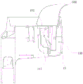
fig. 22 is a schematic structural view of a mop bucket according to a first embodiment of the present invention (a flat mop is omitted):
fig. 23 is a schematic structural view of a second embodiment of the mop bucket of the present invention (omitting the flat mop):
FIG. 24 is a cross-sectional view of FIG. 23;
FIG. 25 is a schematic structural view of a first embodiment of a retaining member according to a third embodiment of the mop bucket of the present invention;
FIG. 26 is a schematic view of the rotation of the second position-limiting sleeve relative to the base of FIG. 25 with the retaining sleeve removed;
FIG. 27 is a schematic structural view of a second embodiment of the retaining member of the third embodiment of the mop bucket of the present invention;
FIG. 28 is a schematic structural view of the locking mechanism of the mop bucket of the present invention in a supporting state (a washboard is provided in the mop bucket);
FIG. 29 is a schematic view of the washboard shown in FIG. 28;
FIG. 30 is an exploded view of the locking mechanism of FIG. 29;
FIG. 31 is a schematic structural view of the second stop collar of FIG. 30;
FIG. 32 is a front view of FIG. 29;
3 FIG. 333 3 is 3a 3 cross 3- 3 sectional 3 view 3 taken 3 along 3 line 3A 3- 3A 3 of 3 FIG. 3 32 3; 3
FIG. 34 is a schematic view of a fourth embodiment of the mop bucket of the present invention (showing a flat mop head);
FIG. 35 is a schematic view of the washboard of the present invention with draining holes;
FIG. 36 is a schematic view of the structure of the wringing rack of the present invention that can be fixedly or rotatably connected to the mop bucket or the washing tub through the lower end of the trunk via the washboard;
FIG. 37 is a schematic view of the wringing rack of FIG. 36 rotating relative to the washboard;
FIG. 38 is a schematic view of another structure of the wringing rack of the present invention, which is fixedly or rotatably connected to the mop bucket or the washing tub through the lower end of the trunk via the washboard;
FIG. 39 is a schematic view of the wringing rack of the present invention connected to the mop bucket or the washing tub through the lower end of the trunk via the washboard and the locking mechanism (showing the wringing rack rotating relative to the washboard);
FIG. 40 is a schematic view of the structure of the wringing rack of the present invention connected to the mop bucket or the washing tub through the lower end of the trunk via the washboard and the locking mechanism;
FIG. 41 is an exploded view of FIG. 40;
FIG. 42 is a schematic view of a water squeezer according to an embodiment of the present invention;
FIG. 43 is a schematic view of the connection structure of FIG. 42 connected to a washing tub;
FIG. 44 is a schematic structural view of a wringer in a second embodiment of the washing tank of the present invention;
FIG. 45 is a schematic view of the connection structure of FIG. 44 to a sink;
FIG. 46 is a schematic view of the first suction cup of FIG. 45;
FIG. 47 is a schematic view of an angle of the water squeezing device according to the third embodiment of the present invention;
FIG. 48 is a schematic view of another angle of the wringer of the third embodiment of the washing tank of the present invention;
FIG. 49 is a schematic view of the connection structure of FIG. 47 to a sink;
FIG. 50 is a schematic view of a water squeezer in a fourth embodiment of the washing tank of the present invention;
FIG. 51 is a cross-sectional view of FIG. 50;
FIG. 52 is a schematic view of the connection structure of FIG. 50 to a sink;
FIG. 53 is a schematic view of a water squeezer in a fifth embodiment of the washing tank of the present invention;
FIG. 54 is a cross-sectional view of FIG. 53;
FIG. 55 is a schematic view of the connection structure of FIG. 53 to a sink;
FIG. 56 is a schematic structural view of a seventh embodiment of the mop bucket of the present invention;
FIG. 57 is a schematic view of FIG. 56 with the filter arrangement omitted;
FIG. 58 is a schematic view of a splash guard according to an embodiment of the present invention;
FIG. 59 is a cross-sectional view of FIG. 58;
FIG. 60 is a schematic view of a seventh embodiment of the filter device of the washing tank of the present invention;
FIG. 61 is a schematic view showing a structure of a washing tank with a flat mop according to a seventh embodiment of the present invention;
FIG. 62 is a schematic structural view of an eighth embodiment of the washing tank of the present invention, wherein the washing tank has a flat mop;
FIG. 63 is a schematic view of a water squeezer in an eighth embodiment of the washing tank of the present invention;
FIG. 64 is a sectional view of a water squeezer in an eighth embodiment of the washing tank of the present invention;
FIG. 65 is a schematic structural view of a filtering device according to an eighth embodiment of the present invention;
fig. 66 is a sectional view of a filter device according to an eighth embodiment of the washing tank of the present invention.
Detailed Description
The present invention will be described in further detail with reference to the following embodiments.
The utility model discloses an embodiment one of a water squeezer for dull and stereotyped mop 40:
as shown in FIGS. 1 to 37, the present invention is a first preferred embodiment of a wringer for a flat mop 40. The water squeezer for the flat mop 40 in the embodiment comprises a squeezing frame 1 and a squeezer 2, wherein the squeezing frame 1 is provided with a squeezing port 11 for inserting the flat mop 40, the squeezer 2 is arranged at the position of the squeezing port 11, and the squeezer 2 can contact with a wiping object on a flat mop head 402 to scrape the wiping object, and the water squeezer further comprises a support member which is arranged below at least one part of the squeezing frame 1, so that the squeezing frame 1 can be positioned at a supported position. The supporting member may be independently disposed under at least a portion of the compression rack 1, and may be formed to extend under at least a portion of the compression rack 1, and in order to achieve better connectivity of the supporting member with the compression rack 1, it is preferable that the supporting member includes a neck portion 12 extending under at least a portion of the compression rack 1 and a trunk portion 3 combined with the neck portion 12. In the embodiment, the squeezing device 2 comprises a scraping plate 21 and a squeezing piece 22 arranged opposite to the scraping plate 21, the squeezing opening 11 is formed between the scraping plate 21 and the squeezing piece, and the upper end surface of the scraping plate 21 is provided with a downward inclined guide slope 211; the buffer chamber 130 comprises a bottom wall and a side peripheral wall, the extrusion frame 1 directly serves as the bottom wall of the buffer chamber 130, and the side walls of the buffer chamber have two: the first side peripheral wall 13 extending upwards from the outer periphery of the bottom wall, the second side peripheral wall 13b opposite to the first side peripheral wall 13, the second side peripheral wall 13b is provided with an inlet 102, the squeezer 2 is also arranged on the second side peripheral wall 13b and is opposite to the inlet 102, the first side peripheral wall guide slope of the first side peripheral wall is such that when the flat mop head 402 is inserted into the squeezing opening 11 to press and squeeze water downwards, most of the squeezed water enters the buffer chamber 130, only a very small part of the water drops into the squeezing opening 11, the wiping object of the flat mop head 402 absorbs the very small part of the water again, and the wiping object can be squeezed to be dry after multiple times of squeezing water. Wherein, in order to realize that the body part 3 can effectively transfer the water squeezed out when the wiping matters on the flat mop head 402 are pressed down while supporting the extrusion frame 1, the body part 3 is provided with a water guide device for transferring the water in the buffer chamber 130, and the water guide device can also be matched with a water pumping device, in view of the simple structure, the water guide means is preferably a water guide passage 31 which penetrates at least partially through the body portion 3, the neck portion 12 has an inlet 121 for introducing water in the buffer chamber 130 into the water guide passage 31, the body portion 3 is provided with an outlet 311 for discharging water in the water guide passage 31, this also realizes that the neck portion 12 has a connection function and also has a relationship with the body portion 3 serving as the water guide passage 31, and the body portion 3 functions as the water guide passage 31 in addition to a support function. In order to prevent most of the water squeezed out from the buffer chamber 130 from splashing out, the buffer chamber 130 further includes a frame cover 10 covering the first side peripheral wall 13 and the second side peripheral wall 13b, and the first side peripheral wall 10 and the frame body may be integrally provided. Wherein the frame cover 10 also has a guiding function, the frame cover 10 has a guiding edge 101 which is inclined downwards towards the guiding slope 211 of the scraper 21, an inlet 102 for water squeezed out by the wiping matters on the flat mop head 402 to enter the buffer chamber 130 is formed between the guiding slope 211 and the guiding edge 101, in order to more smoothly enter the inlet 102 for water squeezed out by the wiping matters on the flat mop head 402 to enter the buffer chamber 130, the guiding edge 101 extends downwards along the length direction with a plurality of guiding sheets 103 which are arranged at intervals, and a sub-inlet 104 which divides the inlet 102 into at least two water inlets to enter the buffer chamber 130 is formed between the adjacent guiding sheets 103. When water squeezed from the mop on the flat mop head 402 enters the inlet 102 in the buffer chamber 130, the water is guided into the buffer chamber 130 by the guiding edge 101 of the cover 10 and the guiding plate 103, and then is guided into the body 3 through the inlet 121 of the neck 12 and discharged from the outlet 311 of the body 3, preferably, the body 3 is further provided with a filtering device for filtering the water in the water guiding channel 31 and then discharging the filtered water through the outlet 311.
The utility model discloses another structure that is arranged in dull and stereotyped mop 40's embodiment one buffer chamber:
as shown in fig. 4 to 7, the buffer chamber 130 includes a bottom wall, a side peripheral wall and a frame cover, and the two side walls of the buffer chamber include: the extrusion frame 1 comprises a frame body which is directly used as the bottom wall of the buffer chamber 130, a first side peripheral wall 13 extending upwards from the outer periphery of the bottom wall, and a second side peripheral wall 13b opposite to the first side peripheral wall 13, wherein the frame body extends downwards to form the first side peripheral wall 13, the center of the frame body is arranged on the second side peripheral wall 13b and is provided with an extruder 2 and a scraper 21 opposite to the extruder 2, an extrusion opening 11 is formed between the scraper 21 and an extrusion piece 22, the upper end face of the scraper 21 is provided with a downward inclined guide slope 211, and the guide slope 211 is positioned below the inlet 102.
The structure of the extrusion 22 of the present invention can take the following four forms:
the extrusion strip, or the extrusion sheet, the water extrusion roller, or the roller is fixedly arranged or movably arranged at the position of the extrusion opening 11 of the extrusion frame 1 through an elastic device.
The extruding part 22 of the embodiment adopts a roller which is movably arranged at the position of the extruding opening 11 of the extruding frame 1 through an elastic device to be matched with the scraping plate 21 for extruding water.
The utility model discloses a realize trunk 3's height-adjustable, can adopt following structure:
the trunk unit 3 includes a first trunk unit 32 and a second trunk unit 33 movable relative to the first trunk unit 32, and the first trunk unit 32 is provided with a stopper device for restricting the movement of the second trunk unit 33. From the viewpoint of processing cost, it is preferable that the second body portion 33 is moved relative to the first body portion 32 in a manual manner in order to achieve fitting with various cleaning tools at an optimum use height;
the first embodiment of the limiting device is as follows:
as shown in fig. 8 to 12, the stopper device includes the elastic member 4 fitted to the inner wall of the first body portion 32, the elastic member 4 and the inner wall of the first body portion 32 are formed with the insertion hole 41 into which the lower end of the second body portion 33 is inserted, and the elastic member 4 tends to be smaller in the insertion hole 41 at all times. When the lower end of the second trunk portion 33 is inserted into the insertion opening 41, the elastic member 4 is pressed, and the elastic member 4 is retracted to fix the second trunk portion 33 in the insertion opening 41 by the elastic restoring force. In order to enhance the fixing force of the elastic member 4, preferably, the elastic member 4 has a notch 42 in a part thereof, a spring 421 and a stopper 422 are provided at a central position of the notch 42, a stopper hole 321 for ejecting a part of the stopper 422 is opened at a position of the first body portion 32 corresponding to the notch 42, and the stopper 422 can be partially ejected from the stopper hole 321 of the first body portion 32 by pressing the elastic member 4 in a state where the elastic member 4 is inserted into the lower end of the second body portion 33.
The second embodiment of the limiting device is as follows:
as shown in fig. 13 to 19, the stopper device includes an elastic sleeve 4 ' fitted around the inner wall of the first body portion 32, and the elastic sleeve 4 ' has a sleeve insertion opening 41 ' into which the lower end of the second body portion 33 is inserted, which is different from the first embodiment: the outer wall of elastic sleeve 4 ' has elasticity convex part 42 ', and it has a first mounting hole 322 that supplies the convex part to pass to open on first trunk 32 to overlap at first trunk 32 outer wall and be equipped with first stop collar 320, and the same second mounting hole 3201 that supplies the convex part to pass is seted up on first stop collar 320, and first stop collar 320 is including lock seat 3202 and the handle 3203 that articulates on lock seat 3202 through the round pin axle, and elasticity convex part 42 ' has the trend of outwards playing handle 3203 all the time. The handle 3203 is pulled downward after the lower end of the second trunk 33 is inserted into the sleeve insertion opening 41 ' of the elastic sleeve 4 ', so that the handle 3203 presses the elastic outer protrusion 42 ' inward, the lower end of the second trunk 33 is effectively positioned in the elastic sleeve 4 ', and if the fixing force of the elastic outer protrusion 42 ' is to be released, the handle 3203 is pulled upward, and the operation of adjusting the height is very convenient.
The third embodiment of the limiting device is as follows:
as shown in fig. 20 and 21, the stopper device includes a positioning sleeve 4 "fitted around the inner wall of the first body portion 32, the positioning sleeve 4" has a sleeve opening 41 "into which the lower end of the second body portion 33 is inserted, a first threaded sleeve 324 is fitted around the outer wall of the first body portion 32, and a second threaded sleeve 323 screwed with the first threaded sleeve 324 is fitted around the lower end of the second body portion 33. The positive locking connection between the first and second trunk parts 32, 33 is achieved relatively simply by a screw-tight fit.
The utility model discloses an embodiment two of a water squeezer for dull and stereotyped mop 40:
the structure of the water squeezer is basically the same as that of the first embodiment of the water squeezer, and the only difference is that: elastically disposed opposite the squeegee 21 is a pressing piece.
The utility model discloses an embodiment three of a wringer for dull and stereotyped mop 40:
the structure of the water squeezer is basically the same as that of the first embodiment of the water squeezer, and the only difference is that: disposed elastically opposite the squeegee 21 is an extrusion strip.
The utility model discloses an embodiment four of a wringer for flat mop 40:
the structure of the water squeezer is basically the same as that of the first embodiment of the water squeezer, and the only difference is that: the periphery of the frame body is not provided with a buffer cavity 130, and the extruder 2 comprises a scraping plate 21 and an extrusion strip movably arranged at the position of an extrusion opening 11 in the extrusion frame 1 through an elastic device.
The embodiment of the utility model for a water squeezer of dull and stereotyped mop 40 is five:
the structure of the water squeezer is basically the same as that of the second embodiment, and the only difference is that: the periphery of the shelf does not have a buffer chamber 130.
The utility model discloses an embodiment six of a wringer for flat mop 40:
the structure of the water squeezer is basically the same as that of the first embodiment of the water squeezer, and the only difference is that: the periphery of the frame body is not provided with a buffer cavity 130, and the extruder 2 comprises a scraping plate 21 and a water squeezing roller which is movably arranged at the position of an extrusion opening 11 in the extrusion frame 1 through an elastic device.
In the cleaning tool of the present invention, which is applied to the above-mentioned water squeezing device for the flat mop 40, the mop bucket 20 and the washing tub 30 are both adapted to be connected to the water squeezing device via a support member, and the description will be made by taking the mop bucket 20 as an example, wherein,
the first embodiment of the mop bucket 20 of the present invention:
as shown in fig. 22, the flat mop 40 comprises a mop bucket 20 and a flat mop 40, wherein the flat mop 40 comprises a mop rod 401 and a flat mop head 402 movably connected to the mop rod 401, a wiping material is arranged on the flat mop head 402, the wiping material can contact with the squeezer 2 on the squeezing frame 1, the squeezer 2 is fixedly connected to the mop bucket 20 through the lower end of a body 3 of a support, and a positioning seat 50 for inserting the lower end of the body 3 is correspondingly arranged on the upper surface of the bottom of the mop bucket 20.
The second embodiment of the mop bucket 20 of the present invention:
as shown in fig. 23 and 24, the difference from the first embodiment of mop bucket 20 is that: satisfy that positioning seat 50 can supply the lower extreme of trunk 3 to insert and establish and can also effectively fix a position, wherein seted up opening 501 on the positioning seat 50, the lower extreme of trunk 3 is equipped with spring 421 and bullet piece 35, spring 421 acts on bullet piece 35 and makes bullet piece 35 part pop out in opening 501 of positioning seat 50, press bullet piece 35 when inserting the lower extreme of trunk 3 and establish, spring 421 is compressed this moment, when waiting to insert and establish in place, bullet piece 35 is located opening 501 of positioning seat 50 under the effect of the resilience force of spring 421, and then be located the lower extreme of trunk 3 on positioning seat 50 effectively.
The third embodiment of the mop bucket 20 of the present invention:
the differences from the first embodiment of mop bucket 20 are: the lower end of the body part 3 can be rotatably connected to the mop bucket 20, the second limiting sleeve 3200 detachably connected to the lower end of the body part 3 is adopted in a rotating mode, the base 60 rotatably connected with the second limiting sleeve 3200 is arranged on the upper surface of the bottom of the mop bucket 20, the squeezer 2 connected to the body part 3 can be contained in the mop bucket 20, and in order not to occupy other spaces of the mop bucket 20, the squeezer after squeezing is preferably contained in a containing cavity used for containing cleaning water in the mop bucket 20. In order to achieve that the wringer does not wobble when supported on the mop bucket 20 via the body 3 to wring the flat mop head 402, the wringer further includes a retaining element disposed on the mop bucket 20 and operatively associated with the body 3 for retaining the body 3 in a fixed position relative to the mop bucket 20 when the body 3 is in a supported position with the wringing frame 1 supported by the body 3.
The first embodiment of the retaining element in this embodiment:
as shown in fig. 25 and 26, the retaining member is a retaining sleeve 70 capable of preventing the second position-limiting sleeve 3200 from rotating relative to the base 60, and the retaining sleeve 70 is capable of sliding relative to the trunk portion 3. When the retaining sleeve 70 slides between the second position-limiting sleeve 3200 and the base 60, the second position-limiting sleeve 3200 is prevented from rotating relative to the base 60.
The second embodiment of the holding member in this embodiment:
as shown in fig. 27, the retaining member is a retainer 70 'disposed at the edge of the opening 501 of the mop bucket 20, the retainer 70' further includes a generally "U" shaped opening 701 'facing the body portion 3, the opening 701' having a first leg 702 'and a second leg 703' disposed opposite to each other for securing the body portion 3. The fixation of the trunk portion 3 can be achieved by directly fixing the trunk portion 3 to the frame opening 701 ' through the first frame leg 702 ' and the second frame leg 703 '.
In order to prevent the wringer from shaking when the wringer is in the working state in the embodiment, in addition to the above two schemes of the holding elements, the wringer can be realized by the following locking mechanism 80:
the locking mechanism 80 is arranged at the joint of the base 60 and the second position-limiting sleeve 3200 to lock the second position-limiting sleeve 3200 and the body part 3 at a required use position, wherein a concave part which is concave upwards from bottom to top is locally arranged at the central position of the second position-limiting sleeve 3200, the base 60 is positioned at the concave part, both ends of the base 60 are open ends, the locking mechanism 80 comprises a collar head part 8011 arranged in the end part of the open end of the base 60 and a collar 801 of a collar tail part 8012 arranged outside the end part of the open end of the base 60, and the peripheral surface of the collar tail part 8012 is provided with clamping teeth 8013; the button 802 includes a base portion 8021 and a free end 8022 formed by extending the base portion 8021 to the base 60, and the base portion 8021 is fixedly connected to the middle portion of the latch 8013; the device further comprises a second limiting sleeve 3200, wherein the tail end of the second limiting sleeve 3200 is hollow and is used for being sleeved outside the clamping ring 801 and the button 802, the free end 8022 of the button 802 is exposed out of the tail end of the second limiting sleeve 3200, and a flange meshed with the clamping teeth 8013 is arranged on the inner peripheral wall of the tail end of the second limiting sleeve 3200; and an elastic element 4 is further included, one end of the elastic element 4 is connected in the base 60, and the other end of the elastic element 4 is connected to the base 8021 of the button 802, so that the latch teeth 8013 of the collar tail portion 8012 always have a tendency to engage with the flange of the inner peripheral wall of the second position-limiting sleeve 3200. When the button 802 is used, the free end 8022 of the button 802 is pressed, the base portion 8021 of the button 802 drives the collar head portion 8011 and the collar tail portion 8012 of the collar 801 to move towards the open end of the base 60, at this time, the latch 8013 of the collar tail portion 8012 is separated from the flange of the inner peripheral wall of the second position-limiting sleeve 3200 so as to adjust the body portion 3 at a desired using position, the elastic member 4 is preferably a compression spring 421, and is in a compressed state, after the body portion 3 is adjusted at the desired using position, the free end 8022 of the button 802 is released, and under the elastic restoring force of the compression spring 421, the latch 8013 of the collar tail portion 8012 is reengaged with the flange of the inner peripheral wall of the second position-limiting sleeve 3200, so that the body portion 3 is fixed at the desired using position.
The fourth embodiment of the mop bucket 20 of the present invention:
as shown in fig. 34, in order to achieve the effect of the mop bucket 20 or the washing tub 30 of cleaning the flat mop head 402, the lower end of the body portion 3 can be fixedly or rotatably connected to the mop bucket 20 through the washboard 90, the washboard 90 can be detachably arranged on the upper surface of the mop bucket 20 or the bottom, and the washboard 90 also has the dual-purpose function of one object, namely, the function of connecting the body portion 3, so that the water squeezer can also be independently matched with the washboard 90 for use.
The embodiment five of the mop bucket 20 of the utility model is as follows:
as shown in fig. 35, the structure of the mop bucket 20 of the present invention is substantially the same as that of the fourth embodiment, the only difference is that the plate body is provided with at least one draining hole 903 for draining water at another position outside the through hole, and the draining hole 903 can prevent excessive water squeezed onto the flat mop head 402 from being deposited on the washboard 90.
The embodiment of the mop bucket 20 of the utility model is six:
on the basis of the first, second, third or fourth embodiment of the mop bucket 20, the squeezing frame 1 is provided with a water inlet part for external water to enter the squeezing port 11, the squeezing frame 1 can be connected to the washing tank 30, and a water tap and the water inlet part on the mop bucket 20 are connected by a water pipe, so that cleaning water on the water tap is guided into the squeezing frame, and the cleaning and dewatering of the wiping objects on the flat mop 40 can be realized, and the dual functions are integrated.
The mop bucket 20 of the utility model has the seventh embodiment:
the difference from the above embodiment is that: the body part 3 is provided with a filtering device for filtering the water in the water guide channel 31 and then discharging the water through the outlet 311, the filtering device of this embodiment comprises a filtering shell 400 (as shown in fig. 60) capable of covering the outlet 311, the filtering shell 400 is provided with at least two filtering holes 4001, the side edge of the filtering shell 400 is provided with a rim 4002, two inner side walls of the mouth part of the outlet 311 of the body part 3 are provided with sliding grooves 3111 for the insertion of the rim 4003 of the filtering shell 400, which is convenient for a user to clean the garbage gathered in the filtering shell 400 in time, as shown in fig. 56 and 57, and in order to prevent the water squeezed out during the squeezing process from being splashed back, a splash guard 500 for preventing the water from splashing is further arranged on the squeezing frame, (as shown in fig. 58 and 59), the splash guard 500 is arranged adjacent to the squeezing opening 11 of the squeezer, wherein the longitudinal section of the splash guard 500 is S in an "S", the inner surface of the splash guard 500 is provided with a shape of "S" guiding the water splashed, wherein the shelf cover 10 has a communication port 1001 (as shown in fig. 61) for re-guiding the splashback water into the pressing port 11, and the bottom of the shelf body 1 is gradually inclined toward the trunk part 3 from the top down, so that the water splashed out of the outer surface of the splash guard 500 can gradually flow toward the trunk part 3 along the shelf body from the top down.
The embodiment eight of the mop bucket 20 of the utility model:
the seventh embodiment of the mop bucket 20 is different in structure in that: the filtering device is disposed in the buffer chamber 130, specifically or disposed at a position where the extrusion opening 11 is in fluid communication with the buffer chamber 130, and the buffer chamber 130 reserves a socket 5004 for inserting the filtering device, wherein as shown in the figure, the filtering device of the present embodiment has a U-shaped cross section, and includes a first filtering wall 5001 in fluid communication with the extrusion opening 11, a second filtering wall 5002 parallel to and spaced from the first filtering wall, and a third filtering bottom wall 5003 connecting the first filtering wall 5001 and the second filtering wall 5002, specifically, the bottom of the third filtering bottom wall 5003 has at least two filtering holes 5003a, and the first filtering wall 5001 has a filtering opening 5001b for allowing water squeezed out when the wiper contacts the wiper on the flat plate mop head 40 to scrape the wiper, and in addition, in order to achieve fluid communication between the filtering device and the buffer chamber 130, the second filtering wall 5002 also has at least two filtering holes 5003a, thirdly, through the at least two filtering holes 5003a at the bottom of the filtering bottom wall 5003 and the at least two filtering holes 5003a of the second filtering wall 5002, the purpose that when the squeezer contacts the wiping matters on the flat mop head 40 to scrape the wiping matters, the squeezed water flows into the filtering opening 5001b is achieved, the filtering is firstly carried out, then the filtering enters the buffer chamber 130, the filtered dirt is remained in the third filtering bottom wall 5003, and finally the filtering device can be detachably connected with the socket so as to be convenient for cleaning the filtering device is achieved, as shown in fig. 62-66.
The embodiment of the washing tank 30 of the present invention is as follows:
as shown in fig. 42 and 43, the connecting structure is a supporting leg 3 ' extending transversely from the peripheral wall of the extrusion frame 1, and correspondingly, the top peripheral edge of the washing tank 30 is provided with a groove 30 ' for accommodating the supporting leg 3 ', and the supporting leg 3 ' is directly clamped in the groove 30 '. The shape of the extruder 2 can be selected in many ways, and preferably, the first extruding member and the second extruding member are extruding strips, or extruding sheets, rotatable water extruding rollers or rolling wheels, and the extruding strips, or extruding sheets, water extruding rollers or rolling wheels are fixed or installed at the position of the extruding opening 11 of the extruding frame 1 through elastic devices. Alternatively, the extruder 2 may be constructed using the wringing devices of the applicant's patents ZL201621281181.0 and ZL201620823490.x or ZL 201620889333.9.
The second embodiment of the washing tank 30 of the present invention:
as shown in fig. 44 and 45, the connection structure is a support rod 300 detachably connected to the lower surface of the extrusion frame 1, correspondingly, the bottom upper surface of the washing tank 30 has a connection seat 310 for the lower end of the support rod to be inserted, the connection seat can be fixedly connected with the bottom upper surface of the washing tank 30 and also can be detachably connected, and the connection mode as detachable connection is: the connection base 310 is a first suction cup 320 ' capable of being absorbed on the upper surface of the bottom of the washing pool 30, the middle of the first suction cup 320 ' is provided with a convex wall 321 extending upwards, the space surrounded by the convex wall 321 is used for accommodating the lower end of the support rod 300, in order to realize the function of guiding the cleaning water of the first suction cup 320, the convex wall 3210 of the first suction cup 320 ' extends downwards to form an extension part 330 capable of extending into the drainage outlet of the washing pool 30, wherein, the convex wall 321, the extension part 330 are communicated with the drainage outlet of the washing pool 30.
The third embodiment of the washing tank 30 of the present invention:
as shown in fig. 47 to 49, the connection structure is an L-shaped support arm 3", a transverse arm 31" of the support arm 3 "is connected to the outer peripheral wall of the extrusion frame 1, a vertical arm 32" of the support arm 3 "is connected to the lateral peripheral wall of the washing pool 30, a second suction cup is arranged on the joint surface of the vertical arm 32" and the lateral peripheral wall of the washing pool 30, and the vertical arm 32 "further has a first wrench 34" hinged to the suction cup. Place the second sucking disc in the side direction perisporium of wash bowl 30 after down pull first spanner 34 "pull up the second sucking disc, make the second sucking disc under the effect of atmospheric pressure, powerful absorption in the side direction perisporium of wash bowl 30, and when will removing the adsorption affinity of second sucking disc, only need upwards pull first spanner 34" can, convenient operation.
The embodiment of the washing tank 30 of the present invention is four:
the connecting structure is a first support 3 ' and a second support 3 ' which can move relatively, the first support 3 ' is positioned in the lateral peripheral wall of the washing pool 30 and is connected with the peripheral wall of the extrusion frame 1, the second support 3 ' is positioned outside the lateral peripheral wall of the washing pool 30, a third attachment 31 ' such as a third suction cup is arranged on the joint surface of the first support 3 ' and the lateral peripheral wall of the washing pool 30, a fourth attachment 32 ' such as a fourth suction cup is arranged on the joint surface of the first support 3 ' and the lateral peripheral wall of the washing pool 30, and a first adjusting piece 5 which can adjust the relative position between the third suction cup and the fourth suction cup is arranged on the second support 3 '. In order to realize that the third sucker of the first bracket 3 'can be adsorbed inside the lateral peripheral wall of the washing tank 30 and the fourth sucker of the second bracket 3 "can be adsorbed outside the lateral peripheral wall of the washing tank 30, the first adjusting part 5 comprises a first screw rod 51 penetrating through the first bracket 3' and the second bracket 3", the head of the first screw rod 51 is meshed with the first bracket 3 ', the tail of the first screw rod 51 extends out of the second bracket 3 "and is hinged with a second wrench 52, and the relative position between the third sucker of the first bracket 3' and the fourth sucker on the second bracket 3" can be adjusted in the state of rotating the second wrench 52. During the use, utilize the gap between first support 3 ' and the second support 3 "to connect the crowded water frame on the side direction perisporium of wash basin 30, rotate second spanner 52 again and make first support 3 ' and second support 3" relative movement, make the third sucking disc that can first support 3 ' adsorb in the side direction perisporium of wash basin 30 and the fourth sucking disc on the second support 3 "pull second spanner 52 and pull third sucking disc and fourth sucking disc after the side direction perisporium of wash basin 30 is outside, make third sucking disc and fourth sucking disc under the effect of atmospheric pressure, powerful absorption is on the side direction perisporium of wash basin 30, and when will removing the adsorption affinity of third sucking disc and fourth sucking disc, only need upwards pull second spanner 52 can.
The embodiment of the washing tank 30 of the utility model is five:
as shown in fig. 53 to 55, the connection structure includes a connection frame 3 ″ supporting the compression frame 1, the connection frame 3 'has a first connection port 31' and a second connection port 32 'extending from both sides of the lateral side of the wash basin 30 in the transverse direction, respectively, the first connection port 31' is detachably connected with a first connection rod 33 ', and the distal end of the first connection rod 33' is connected to the first lateral wall of the wash basin 30 via a first connection mechanism 6; the second connection port 32 ' is detachably connected with a second connection rod 34 ', the tip of the second connection rod 34 ' being connected with a second lateral wall of the wash basin 30 via a second connection mechanism 7, wherein the first and second lateral walls are oppositely arranged, which implementation enables to suspend the extrusion frame 1 in a central position of the wash basin 30. Wherein the detachable connection of the first connecting rod 33 'with the first connecting port 31' and the second connecting rod 34 'with the second connecting port 32' is realized by means of a spring 36 and a dog 35 provided on the first connecting rod 33 'and the second connecting rod 34', which spring 36 acts on the dog 35 to partially eject the dog 35 out of the tail of the first connecting port 31 'and the second connecting port 32', so as to quickly realize the plugging of the first connecting rod 33 'with the first connecting port 31', the second connecting rod 34 'and the second connecting port 32'.
And the first connecting means 6 are a third bracket 61 and a fourth bracket 62 which are relatively movable, the third bracket 61 and the fourth bracket 62 being arranged substantially in the same manner as the first bracket 3 'and the second bracket 3 "of the fourth implementation, the only difference being that the third bracket 61 has a third connecting port 611 at the top end thereof for connection of the distal end of the first connecting rod 33' ″. The method specifically comprises the following steps: the third bracket 61 is located inside the first lateral wall of the washing tank 30 and connected with the outer circumferential wall of the pressing frame 1, the fourth bracket 62 is located outside the first lateral wall of the washing tank 30, and the top end of the third bracket 61 has a third connection port 611 for connecting the end of the first connection rod 33' ″, the joint surface of the third bracket 61 and the first lateral wall of the washing tank 30 is provided with a fifth suction cup, the joint surface of the fourth bracket 62 and the first lateral wall of the washing tank 30 is provided with a sixth suction cup, the fourth bracket 62 is provided with a second adjusting member 8 capable of adjusting the relative position between the fifth suction cup and the sixth suction cup, the second adjusting member 8 comprises a second lead screw 81 penetrating through the third bracket 61 and the fourth bracket 62, the head of the second lead screw 81 is engaged with the third bracket 61, the tail of the second lead screw 81 extends out of the fourth bracket 62 and is hinged with a third wrench 82, and the third wrench 82 is capable of adjusting the fifth suction cup of the third bracket 61 and the sixth suction cup on the fourth bracket 62 in a state of rotating the third wrench 82 Relative positions of the third bracket 61 and the fourth bracket 62 are substantially the same as those of the fourth embodiment of the washing tub 30, and the third bracket 61 and the fourth bracket 62 are adjusted by the second adjusting member 8 in such a manner that the pressing frame 1 is connected to the first lateral wall of the washing tub 30 by the third bracket 61 and the fourth bracket 62, which will not be described again.
In addition, the second connecting mechanism 7 is a fifth bracket 71 and a sixth bracket 72 which can move relatively, the fifth bracket 71 is positioned inside the second lateral wall of the washing tank 30 and connected with the outer peripheral wall of the squeezing frame 1, the sixth bracket 72 is positioned outside the second lateral wall of the washing tank 30, and the top end of the fifth bracket 71 is provided with a fifth connecting port 711 for connecting the tail end of the second connecting rod 34' ″, the joint surface of the fifth bracket 71 and the second lateral wall of the washing tank 30 is provided with a seventh sucking disc, the joint surface of the fifth bracket 71 and the second lateral wall of the washing tank 30 is provided with an eighth sucking disc, the sixth bracket 72 is provided with a third adjusting member 9 capable of adjusting the relative position between the seventh sucking disc and the eighth sucking disc, the third adjusting member 9 comprises a third screw 91 which penetrates through the fifth bracket 71 and the sixth bracket 72, the head of the third screw 91 is engaged with the fifth bracket 71, the tail of the third screw 91 extends out of the sixth bracket 72 and is hinged with a fourth wrench 92, the relative positions of the seventh suction cup of the fifth bracket 71 and the eighth suction cup of the sixth bracket 72 can be adjusted by rotating the fourth wrench 92, and the manner of connecting the pressing frame 1 to the second lateral wall of the washing tub 30 by using the fifth bracket 71 and the sixth bracket 72 and the manner of adjusting the fifth bracket 71 and the sixth bracket 72 by using the third adjusting member 9 are substantially the same as those of the fourth embodiment of the washing tub 30, and thus, detailed description thereof is omitted.
The embodiment of the washing tank 30 of the utility model is six:
on the basis of the first, second, third or fourth embodiment of the washing tank 30, the squeezing frame 1 is provided with a water inlet part for external water to enter the squeezing port 11, the squeezing frame 1 can be connected to the washing tank 30, a water tap and the water inlet part on the washing tank 30 are connected through a water pipe, cleaning water on the water tap is guided into the squeezing frame, cleaning and dewatering of the wiping objects on the flat mop 40 can be realized, and double functions are integrated.
Claims (37)
1. The utility model provides a water squeezer for dull and stereotyped mop, including extrusion frame (1) and squeezer (2), extrusion frame (1) on offer and supply dull and stereotyped mop (40) male extrusion mouth (11), squeezer (2) set up in extrusion mouth (11) position, squeezer (2) can contact the wiper on dull and stereotyped mop (40) and scrape the wiper, its characterized in that: the extrusion frame (1) is provided with a buffer chamber (130) which can buffer water extruded by the extrusion opening (11), and at least one wall of the buffer chamber (130) is provided with an inlet (102) which is communicated with the extrusion opening (11) in a fluid mode.
2. The wringer for a flat mop of claim 1, wherein: the buffer chamber (130) comprises a bottom wall and a side peripheral wall, the extrusion frame (1) is directly used as the bottom wall of the buffer chamber (130), and the side walls of the buffer chamber have two parts: a first side peripheral wall (13) extending upwards from the outer periphery of the bottom wall, and a second side peripheral wall (13b) opposite to the first side peripheral wall (13), wherein the inlet (102) is arranged on the second side peripheral wall (13b), and the squeezer (2) is also arranged on the second side peripheral wall (13b) and is opposite to the inlet (102).
3. The wringer for a flat mop of claim 2, wherein: the buffer chamber (130) further comprises a frame cover (10) covering the first side peripheral wall (13) and the second side peripheral wall (13 b).
4. The wringer for a flat mop of claim 3, wherein: the squeezer (2) comprises a scraping plate (21) positioned below the inlet (102) and a squeezing piece (22) arranged opposite to the scraping plate (21), the squeezing opening (11) is formed between the scraping plate (21) and the squeezing piece (22), and the upper end surface of the scraping plate (21) is provided with a downward inclined guide slope (211).
5. The wringer for a flat mop of claim 4, wherein: the buffer chamber (130) comprises a bottom wall, side peripheral walls and a frame cover, and the side walls of the buffer chamber are two: the extrusion frame (1) comprises a frame body which is directly used as the bottom wall of the buffer chamber (130), the frame cover (10) extends downwards to form the first side peripheral wall (13), the center of the frame body is arranged on the second side peripheral wall (13b) and is provided with the extruder (2) and a scraper (21) which is arranged opposite to the extruder (2), the extrusion opening (11) is formed between the scraper (21) and the extrusion piece (22), the upper end surface of the scraper (21) is provided with a downward inclined guide slope (211), and the guide slope (211) is positioned below the inlet (102).
6. The wringer for a flat mop of claim 5, wherein: the frame cover (10) has a guide edge (101) inclined downward toward a guide slope (211) of the squeegee (21).
7. The wringer for a flat mop of claim 6, wherein: the guide edge (101) extends downwards along the length direction to form guide vanes (103) which are arranged at intervals, and a sub-inlet (104) which divides the inlet (102) into at least two water inlets into the buffer chamber (130) is formed between the adjacent guide vanes (103).
8. The wringer for a flat mop of any one of claims 1 to 7, wherein: the extrusion device also comprises a connecting structure, wherein the connecting structure is connected with the extrusion frame (1) so that the extrusion frame (1) can be suspended at the connected position.
9. The wringer for a flat mop of claim 8, wherein: the connecting structure is a support member arranged under at least a part of the extrusion frame (1) so that the extrusion frame (1) can be located at a supported position.
10. The wringer for a flat mop of claim 9, wherein: the support member includes a neck portion (12) detachably connected to at least a portion of the squeeze frame (1) and a trunk portion (3) combined with the neck portion (12).
11. The wringer for a flat mop of claim 10, wherein: the neck (12) is formed to extend directly from under at least a portion of the extrusion frame (1).
12. The wringer for a flat mop of claim 11, wherein: the body part (3) is provided with a water guide device for transferring water in the buffer chamber (130).
13. The wringer for a flat mop of claim 12, wherein: the water guide device is a water guide channel (31) which at least partially penetrates through the body part (3).
14. The wringer for a flat mop of claim 13, wherein: the neck portion (12) has an inlet (121) for introducing water in the buffer chamber (130) into the water guide channel (31), and the body portion (3) is provided with a discharge port (311) for discharging water in the water guide channel (31).
15. The wringer for a flat mop of claim 14, wherein: the body part (3) is also internally provided with a filtering device which filters the water in the water guide flow passage (31) and then discharges the water through the discharge port (311), and/or the buffer chamber (130) is internally provided with a filtering device at the inlet (102).
16. The wringer for a flat mop of any one of claims 4 or 5, wherein: the extrusion part (22) comprises an extrusion strip, an extrusion sheet, a water extrusion roller or a roller which is fixedly arranged or movably arranged at the position of the extrusion opening (11) of the extrusion frame (1) through an elastic device.
17. The wringer for a flat mop of any one of claims 10 to 15, wherein: the trunk part (3) comprises a first trunk part (32) and a second trunk part (33) which can move relative to the first trunk part (32), and the first trunk part (32) is provided with a limiting device which limits the movement of the second trunk part (33).
18. The wringer for a flat mop of claim 17, wherein: the second body part (33) is moved relative to the first body part (32) manually.
19. The wringer for a flat mop of claim 18, wherein: the limiting device comprises an elastic piece (4) nested on the inner wall of the first body part (32), a socket (41) for inserting the lower end of the second body part (33) is formed on the elastic piece (4) and the inner wall of the first body part (32), and the elastic piece (4) always tends to reduce the socket (41).
20. The wringer for a flat mop of claim 19, wherein: the elastic piece (4) is provided with a notch (42) at a local part, a spring (421) and a limiting block (422) are arranged at the central position of the notch (42), a limiting opening (321) for popping out the limiting block (422) is formed in the position, corresponding to the notch (42), of the first body part (32), and the elastic piece (4) can be pressed to enable the limiting block (422) to pop out of the limiting opening (321) of the first body part (32) partially under the condition that the elastic piece (4) is inserted into the lower end of the second body part (33).
21. The wringer for a flat mop of claim 20, wherein: the limiting device comprises an elastic sleeve (4') sleeved on the inner wall of the first trunk part (32), the elastic sleeve (4 ') has a sleeve insertion opening (41') into which the lower end of the second body part (33) is inserted, the outer wall of the elastic sleeve (4 ') is provided with an elastic convex part (42 '), the first body part (32) is provided with a first mounting hole (322) for the convex part (42 ') to pass through, a first stop collar (320) is sleeved on the outer wall of the first trunk part (32), the first limiting sleeve (320) is also provided with a second mounting hole (3201) for the outward protruding part (42') to pass through, the first limiting sleeve (320) comprises a lock seat (3202) and a handle (3203) hinged on the lock seat (3202) through a pin shaft, the resilient outward protrusion (42') always has a tendency to spring the handle (3203) outward.
22. The wringer for a flat mop of claim 20, wherein: the limiting device comprises a positioning sleeve (4 ') sleeved on the inner wall of the first body part (32), the positioning sleeve (4 ') is provided with a sleeve opening (41 ') for inserting the lower end of the second body part (33), a first threaded sleeve (324) is sleeved on the outer wall of the first body part (32), and a second threaded sleeve (323) in threaded connection with the first threaded sleeve (324) is sleeved on the lower end of the second body part (33).
23. A cleaning implement to which the wringer for a flat mop of any one of claims 1 to 22 is applied, characterized in that: the mop comprises a mop bucket (20) or a washing pool (30) and a flat mop (40), wherein the flat mop (40) comprises a mop rod (401) and a flat mop head (402) movably connected to the mop rod (401), the flat mop head (402) is provided with a wiping material, and the wiping material can contact with an extruder (2) on the extrusion frame (1).
24. The cleaning implement of claim 23, wherein: the lower end of the trunk part (3) can be fixedly connected to the mop bucket (20) or the washing tank (30).
25. The cleaning implement of claim 24, wherein: the upper surface of the bottom of the mop bucket (20) or the washing tank (30) is provided with a positioning seat (50) for the lower end of the trunk part (3) to be inserted.
26. The cleaning implement of claim 25, wherein: an opening (501) is formed in the positioning seat (50), a spring (421) and an elastic block (35) are arranged at the lower end of the body part (3), and the spring (421) acts on the elastic block (35) to enable part of the elastic block (35) to be ejected out of the opening (501) of the positioning seat (50).
27. The cleaning implement of claim 26, wherein: the lower end of the trunk part (3) can be rotatably connected to the mop bucket (20) or the washing tank (30).
28. The cleaning implement of claim 27, wherein: the body part (3) further comprises a second limiting sleeve (3200) detachably connected to the lower end of the body part (3), and a base (60) rotatably connected with the second limiting sleeve (3200) is arranged on the upper surface of the bottom of the mop bucket (20) or the washing pool (30).
29. The cleaning implement of claim 28, wherein: and a holding element arranged on the mop bucket (20) or the washing pool (30), wherein the holding element can be in operable communication with the body part (3) and is used for holding the body part (3) in a fixed state relative to the mop bucket (20) or the washing pool (30) in a state that the body part (3) supports the squeezing frame (1).
30. The cleaning implement of claim 29, wherein: the retaining element is a retaining sleeve (70) capable of preventing the second limiting sleeve (3200) from rotating relative to the base (60), and the retaining sleeve (70) can slide relative to the trunk part (3).
31. The cleaning implement of claim 30, wherein: the holding element is a holding frame (70 ') arranged at the edge of the opening (501) of the mop bucket (20), the holding frame (70') further comprises a frame opening (701 ') which is approximately U-shaped and faces the body part (3), and the frame opening (701') is provided with a first frame supporting leg (702 ') and a second frame supporting leg (703') which are oppositely arranged and used for fixing the body part (3).
32. The cleaning implement of claim 28, wherein: the device also comprises a locking mechanism (80) which is arranged at the joint of the base (60) and the second position-limiting sleeve (3200) so as to lock the second position-limiting sleeve (3200) and the trunk part (3) at a required use position.
33. The cleaning implement of claim 32, wherein: a concave part which is concave upwards from bottom to top is locally arranged at the central position of the second limit sleeve (3200), the base (60) is positioned at the concave part, both ends of the base (60) are open ends,
the locking mechanism (80) comprises:
the clamping ring (801) comprises a clamping ring head part (8011) arranged in the open end part of the base (60) and a clamping ring tail part (8012) arranged outside the open end part of the base (60), wherein the clamping ring tail part (8012) is provided with clamping teeth (8013) on the peripheral surface;
the button (802), the button (802) includes the basal portion (8021) and extends the free end (8022) that forms from the basal portion (8021) to the said base (60), the said basal portion (8021) is affixed to the middle part of the said latch (8013);
the tail end of the second limiting sleeve (3200) is hollow and is sleeved outside the clamping ring (801) and the button (802), the free end (8022) of the button (802) is exposed out of the tail end of the second limiting sleeve (3200), and a flange meshed with the clamping teeth (8013) is arranged on the inner peripheral wall of the tail end of the second limiting sleeve (3200);
one end of the elastic element (4) is connected into the base (60), the other end of the elastic element (4) is connected onto the base (8021) of the button (802), and the latch (8013) of the clamping ring tail part (8012) always tends to be meshed with the flange of the inner peripheral wall of the second limiting sleeve (3200).
34. The cleaning implement according to any one of claims 27 to 33, wherein: the lower end of the trunk part (3) can be fixedly or rotatably connected to the mop bucket (20) or the washing tank (30) through a washboard (90), and the washboard (90) can be detachably arranged on the upper surface of the bottom of the mop bucket (20) or the washing tank (30).
35. The cleaning implement of claim 34, wherein: the washboard (90) comprises a plate body, a local concave area (901) is arranged at the central part of the plate body, and convex ribs (902) are arranged on the local concave area (901) at intervals.
36. The cleaning implement of claim 35, wherein: the other parts of the plate body outside the concave area (901) are provided with at least one draining hole (903) for draining water.
37. A cleaning implement according to claim 35 or 36 wherein: the washing tank (30) is a ceramic washing tank (30).
Priority Applications (1)
| Application Number | Priority Date | Filing Date | Title |
|---|---|---|---|
| CN201921620531.5U CN212489801U (en) | 2019-09-26 | 2019-09-26 | Water squeezer for flat mop and cleaning tool applying same |
Applications Claiming Priority (1)
| Application Number | Priority Date | Filing Date | Title |
|---|---|---|---|
| CN201921620531.5U CN212489801U (en) | 2019-09-26 | 2019-09-26 | Water squeezer for flat mop and cleaning tool applying same |
Publications (1)
| Publication Number | Publication Date |
|---|---|
| CN212489801U true CN212489801U (en) | 2021-02-09 |
Family
ID=74386346
Family Applications (1)
| Application Number | Title | Priority Date | Filing Date |
|---|---|---|---|
| CN201921620531.5U Active CN212489801U (en) | 2019-09-26 | 2019-09-26 | Water squeezer for flat mop and cleaning tool applying same |
Country Status (1)
| Country | Link |
|---|---|
| CN (1) | CN212489801U (en) |
-
2019
- 2019-09-26 CN CN201921620531.5U patent/CN212489801U/en active Active
Similar Documents
| Publication | Publication Date | Title |
|---|---|---|
| CN109008855B (en) | Cleaning tool | |
| CN210204644U (en) | Mop bucket for cleaning and squeezing flat mop | |
| CN213216778U (en) | Cleaning tool for squeezing flat mop | |
| CN213850543U (en) | Extrusion flat mop cleaning device | |
| CN212489801U (en) | Water squeezer for flat mop and cleaning tool applying same | |
| CN111973101B (en) | Cleaning device and method for cleaning tool by using same | |
| CN211796274U (en) | Water squeezer for flat mop and cleaning tool applying same | |
| CN111839391A (en) | Water squeezer for flat mop and cleaning tool applying same | |
| CN215457783U (en) | Mop bucket is washd in slant extrusion | |
| CN211066455U (en) | Flat mop cleaning device | |
| CN213464930U (en) | A burnisher for dull and stereotyped mop and applied this burnisher | |
| CN212140360U (en) | Water squeezer for flat mop and cleaning tool applying same | |
| CN209107255U (en) | Foamed cotton mop cleaning tool | |
| WO2004100754A1 (en) | Arrangement for a floor mop provided with a handle | |
| CN212879207U (en) | Water squeezer for flat mop | |
| CN219763280U (en) | Multipurpose mop bucket | |
| CN211723041U (en) | Water squeezer for flat mop and cleaning tool applying same | |
| CN211704491U (en) | Cleaning device with water squeezing bag | |
| CN212879206U (en) | Water squeezer for flat mop | |
| CN217610930U (en) | Mop cleaning tool | |
| CN211704492U (en) | Scraping and washing piece and cleaning device comprising same | |
| CN215128151U (en) | Flat mop free of hand washing | |
| CN217338478U (en) | Easy-to-dismount flat mop cleaning barrel | |
| CN219742640U (en) | Mop cleaning machine | |
| CN217338483U (en) | Mop bucket fixed by suction disc |
Legal Events
| Date | Code | Title | Description |
|---|---|---|---|
| GR01 | Patent grant | ||
| GR01 | Patent grant |