EP1468132B1 - Hybrid cords, method for obtaining same and composite fabrics incorporating same - Google Patents
Hybrid cords, method for obtaining same and composite fabrics incorporating same Download PDFInfo
- Publication number
- EP1468132B1 EP1468132B1 EP03706357A EP03706357A EP1468132B1 EP 1468132 B1 EP1468132 B1 EP 1468132B1 EP 03706357 A EP03706357 A EP 03706357A EP 03706357 A EP03706357 A EP 03706357A EP 1468132 B1 EP1468132 B1 EP 1468132B1
- Authority
- EP
- European Patent Office
- Prior art keywords
- crown
- ply
- cables
- core
- hooping
- Prior art date
- Legal status (The legal status is an assumption and is not a legal conclusion. Google has not performed a legal analysis and makes no representation as to the accuracy of the status listed.)
- Expired - Lifetime
Links
Images

Classifications
-
- D—TEXTILES; PAPER
- D02—YARNS; MECHANICAL FINISHING OF YARNS OR ROPES; WARPING OR BEAMING
- D02G—CRIMPING OR CURLING FIBRES, FILAMENTS, THREADS, OR YARNS; YARNS OR THREADS
- D02G3/00—Yarns or threads, e.g. fancy yarns; Processes or apparatus for the production thereof, not otherwise provided for
- D02G3/22—Yarns or threads characterised by constructional features, e.g. blending, filament/fibre
-
- B—PERFORMING OPERATIONS; TRANSPORTING
- B60—VEHICLES IN GENERAL
- B60C—VEHICLE TYRES; TYRE INFLATION; TYRE CHANGING; CONNECTING VALVES TO INFLATABLE ELASTIC BODIES IN GENERAL; DEVICES OR ARRANGEMENTS RELATED TO TYRES
- B60C9/00—Reinforcements or ply arrangement of pneumatic tyres
- B60C9/005—Reinforcements made of different materials, e.g. hybrid or composite cords
-
- D—TEXTILES; PAPER
- D02—YARNS; MECHANICAL FINISHING OF YARNS OR ROPES; WARPING OR BEAMING
- D02G—CRIMPING OR CURLING FIBRES, FILAMENTS, THREADS, OR YARNS; YARNS OR THREADS
- D02G3/00—Yarns or threads, e.g. fancy yarns; Processes or apparatus for the production thereof, not otherwise provided for
- D02G3/44—Yarns or threads characterised by the purpose for which they are designed
- D02G3/48—Tyre cords
-
- Y—GENERAL TAGGING OF NEW TECHNOLOGICAL DEVELOPMENTS; GENERAL TAGGING OF CROSS-SECTIONAL TECHNOLOGIES SPANNING OVER SEVERAL SECTIONS OF THE IPC; TECHNICAL SUBJECTS COVERED BY FORMER USPC CROSS-REFERENCE ART COLLECTIONS [XRACs] AND DIGESTS
- Y10—TECHNICAL SUBJECTS COVERED BY FORMER USPC
- Y10T—TECHNICAL SUBJECTS COVERED BY FORMER US CLASSIFICATION
- Y10T152/00—Resilient tires and wheels
- Y10T152/10—Tires, resilient
- Y10T152/10495—Pneumatic tire or inner tube
- Y10T152/10522—Multiple chamber
- Y10T152/10576—Annular chambers
- Y10T152/10594—Mutually free walls
-
- Y—GENERAL TAGGING OF NEW TECHNOLOGICAL DEVELOPMENTS; GENERAL TAGGING OF CROSS-SECTIONAL TECHNOLOGIES SPANNING OVER SEVERAL SECTIONS OF THE IPC; TECHNICAL SUBJECTS COVERED BY FORMER USPC CROSS-REFERENCE ART COLLECTIONS [XRACs] AND DIGESTS
- Y10—TECHNICAL SUBJECTS COVERED BY FORMER USPC
- Y10T—TECHNICAL SUBJECTS COVERED BY FORMER US CLASSIFICATION
- Y10T428/00—Stock material or miscellaneous articles
- Y10T428/29—Coated or structually defined flake, particle, cell, strand, strand portion, rod, filament, macroscopic fiber or mass thereof
- Y10T428/2913—Rod, strand, filament or fiber
Definitions
- the present invention relates to hybrid cables, a method for obtaining them and a composite fabric usable in a tire which incorporates said cables.
- the invention also relates to a tire and a mounted assembly that each incorporate such a composite fabric.
- a solution conventionally used for these "high speed" tire architectures consists in covering the working crown plies of these tires, which comprise metal or textile reinforcing elements, by a so-called hooping top ply, usually reinforced by textile cables.
- This crowning crown ply which is for example arranged radially outside the crown reinforcement of the tire, is characterized in that the cables which reinforce it are arranged in a spiral at an angle of 0 ° or close to 0. ° with the median circumferential plane of the tire. It is also known to have strips or relatively narrow plies at an angle of about 0 ° in place of the aforementioned cables, to fulfill a fretting function of the crown reinforcement.
- a major disadvantage of these hybrid cables with twisted structure lies in the excessive hooping tension that presents the sheet comprising these cables, including at reduced speeds typically less than 120 km / h, (i.e. relatively small deformations).
- a rolling noise due to the tire is significant at these speeds, which represents a significant source of discomfort for the occupants of the vehicle.
- the value of the ratio (final tangent modulus / initial tangent modulus) which characterizes the hybrid cables according to the invention is greater than those of the same ratios characterizing the hybrid cables obtained to date, which are always less than 10.
- this ratio is greater than 12 for the hybrid cables according to the invention, and it is for example between 12 and 30.
- the present invention is in no way limited to use in hoop crimping webs of these hybrid cables, and that it encompasses any use in tires which may be of the tourism type or intended to carry heavy loads, for example heavy-duty tires, agricultural or civil engineering.
- the hybrid cables according to the invention make it possible to improve the high speed endurance (typically greater than 120 km / h) of the tire crown reinforcement, the top of which is reinforced by these cables.
- hybrid cable is meant in the present description a composite cable, i.e. consisting of at least two materials of different nature and / or properties.
- initial tangent modulus of the hybrid cable according to the invention is meant in the present description the slope of the tangent to the force / elongation curve of this cable corresponding to zero elongation.
- final tangent module of this hybrid cable is meant the slope of the tangent to the force / elongation curve of said cable for an elongation corresponding to its rupture.
- the hybrid cables according to the invention each have a force / elongation curve which is very close to the tracing of the aforementioned tangents to this curve respectively corresponding to a zero elongation and to the breaking of the cable, which results in a decoupling of the tangent modules of said cable at low and high deformations (ie at respectively reduced and high speeds of rolling).
- said hybrid cables are of guiped type, comprising a textile core of initial modulus of less than 900 cN / tex and a textile guipe of initial modulus higher than 1300 cN / tex which is wound on said soul.
- initial module of the core or the guipe is meant in the present description the low-strain extension module of each of these components which has previously been extracted hybrid cable guiped.
- This initial modulus is defined as the slope of the linear part of the force / elongation curve of the unrefined core or web, measured just after a standard pretension of 0.5 cN / tex.
- gimped cable is meant by definition in the present description a "straight" soul on which is wound a guipe, for example helically.
- guipe for example helically.
- US patent documents US-A-4,343,343 and US-A-4,893,665 for the description of gimped cables meeting this definition.
- the term "wire” designates both a yarn based on a multitude of elementary filaments of small diameter which are twisted together (for example a yarn based on one hundred elementary filaments each having a similar diameter about ten microns), a single monofilament.
- Monofilament means a unit filament (not twisted by definition) whose diameter or thickness D (ie the smallest transverse dimension of its cross section when it is not circular) is at least equal. at 40 ⁇ m (minimum titre of 1.7 tex).
- This definition thus covers both monofilaments of substantially cylindrical shape (i.e, circular section) or oblong monofilaments, of flattened shape, or strips or films of thickness D.
- the hybrid cable guizza is such that said core consists of a single yarn and said guipe consists of one or more yarns twisted together, preferably two to four yarns twisted together.
- the yarn forming the core has been subjected to a torsion of the order of several tens or even several hundred revolutions / meter, before proceeding to the winding of the guipe on said core.
- the hybrid cable guitig is such that said core consists of several yarns twisted together and said yoke consists of one or more yarns twisted together.
- the hybrid cable guidozens is such that said core consists of a monofilament and said guipe consists of a single yarn or several yarns twisted together.
- the hybrid cable guitig is such that said core consists of a single yarn or several yarns twisted together and said yoke consists of a monofilament.
- the hybrid cable guidozens is such that said core and said guipe are each made of a monofilament.
- the yarn count was determined on at least three samples, each corresponding to a length of 50 m, by weighing this length of yarn.
- the title is given in tex (weight in g of 1000 m of yarn - booster: 0.111 tex equal to 1 denier).
- the elongation at break is indicated in%.
- the wrapped hybrid cable comprises an aliphatic polyamide core, such as a polyamide 6,6, and an aromatic polyamide yarn, such as aramid, or cellulose high modulus of origin crystal-liquid.
- the hybrid cable guitig is such that said core has an elongation at break greater than 10%.
- the hybrid cable covered has a force curve (daN) / elongation (%) having a transition point, below which the extension module of the cable is substantially equal to that of the the core and beyond which the module in extension of this cable is substantially equal to that of the guipe, this transition point corresponding to an elongation of between 1 and 7%, preferably between 2 and 4%.
- transition point (or point of change of slope) is the point corresponding to the elongation for which the two tangents with zero elongation and rupture intersect.
- This assembly is for example carried out by means of a volumetric wiring device and a ring type loom.
- a composite fabric according to the invention comprises a rubber composition based on at least one diene elastomer which is reinforced by said hybrid cables according to the invention (ie each having a ratio (final tangent modulus / initial tangent modulus) greater than 10 ), and this composite fabric can be used advantageously in a tire.
- diene elastomer in known manner an elastomer derived at least in part (ie a homopolymer or a copolymer) of monomers dienes that is to say monomers carrying two carbon-carbon double bonds, conjugated or otherwise.
- this rubber composition is based on at least one diene elastomer whose molar content of units derived from conjugated dienes is greater than 15% (such a diene elastomer is commonly called "essentially unsaturated").
- diene elastomers such as butyl rubbers or copolymers of dienes and alpha-olefins of the EPDM type do not fall within the above definition and may be termed "essentially saturated” diene elastomers. "(molar rate of units derived from dienes always less than 15%).
- this rubber composition is based on at least one diene elastomer whose molar content of units derived from conjugated dienes is greater than 50% (such a diene elastomer is commonly called "highly unsaturated”).
- This diene elastomer is then preferably selected from the group consisting of polybutadienes, natural rubber, synthetic polyisoprenes, the various butadiene copolymers, the various isoprene copolymers, and mixtures of these elastomers.
- Particularly suitable polybutadienes are those having a 1,2-unit content of between 4% and 80% or those having a cis-1,4 content of greater than 80%.
- cis-1,4-polyisoprenes are particularly suitable, preferably those having a cis-1,4 bond ratio greater than 90%.
- copolymers of butadiene or isoprene is meant in particular the copolymers obtained by copolymerization of at least one of these two monomers with one or more vinylaromatic compounds having from 8 to 20 carbon atoms.
- Suitable vinylaromatic compounds are, for example, styrene, ortho-, meta-, para-methylstyrene, the commercial "vinyl-toluene" mixture, para-tert-butylstyrene, methoxystyrenes, chlorostyrenes, vinylmesitylene, divinylbenzene, vinylnaphthalene.
- the copolymers may contain between 99% and 20% by weight of diene units and between 1% and 80% by weight of vinylaromatic units.
- butadiene or isoprene copolymers mention will preferably be made of butadiene-styrene copolymers, isoprene-butadiene copolymers, isoprene-styrene copolymers or isoprene-butadiene-styrene copolymers.
- a diene elastomer chosen from the group of "highly unsaturated" diene elastomers consisting of polybutadienes (BR), natural rubber (NR), synthetic polyisoprenes (IR) and butadiene-styrene copolymers ( SBR), isoprene-butadiene copolymers (BIR), isoprene-styrene copolymers (SIR), butadiene-styrene-isoprene copolymers (SBIR) and mixtures of these elastomers.
- BR polybutadienes
- NR natural rubber
- IR synthetic polyisoprenes
- SBR butadiene-styrene copolymers
- BIR isoprene-butadiene copolymers
- SIR isoprene-styrene copolymers
- SBIR butadiene-styrene-isoprene copolymers
- the rubber composition of the composite fabric according to the invention comprises predominantly (ie in a mass fraction greater than 50%) or in all one or more "highly unsaturated” diene elastomers as defined above, optionally in combination with one or more "essentially saturated” or non-dienic diene elastomers used in a minority capacity, and / or in combination with polymers other than elastomers (for example thermoplastic polymers) also used in a minority capacity.
- the rubber compositions of the composite fabrics according to the invention also comprise all or part of the additives normally used in the manufacture of tires, such as reinforcing fillers such as carbon black or silica, anti-aging agents, for example antioxidants, extension oils, plasticizers or agents facilitating the use of the compositions in the green state, a crosslinking system based on either sulfur, or sulfur and / or peroxide donors, accelerators, activators or vulcanization retarders, acceptors and donors of methylene, resins, known adhesion promoter systems of the "RFS" type (resorcinol-formaldehyde-silica) or metal salts, especially cobalt salts.
- additives normally used in the manufacture of tires such as reinforcing fillers such as carbon black or silica, anti-aging agents, for example antioxidants, extension oils, plasticizers or agents facilitating the use of the compositions in the green state, a crosslinking system based on either sulfur, or sulfur and / or peroxide donors, accelerators,
- the composite fabric according to the invention can be in various forms, for example in the form of a sheet, a strip, a strip or a rubber block in which the metal reinforcement is incorporated by means of various means known to those skilled in the art, such as, for example, molding, calendering or extrusion means.
- this tire is such that said hooping crown ply is disposed radially outside said reinforcing crown ply or plies.
- this tire is such that said hooping crown ply is disposed radially inside said carcass ply.
- this tire is such that said crown comprises at least two superimposed reinforcing crown plies each comprising parallel cables which are crossed from one ply to the other by making with said circumferential direction of angles ( ⁇ , ⁇ ) between 10 and 45 degrees, and said hooping crown ply is disposed between said reinforcing top plies.
- this tire is such that said crown comprises at least two superimposed reinforcing crown plies each comprising parallel cables which are crossed from one ply to the other by making with said circumferential direction of the angles ( ⁇ , ⁇ ) between 10 and 45 degrees, and such that said hooping crown ply is disposed between said carcass ply and the reinforcing crown ply which is disposed the most radially inside.
- said tire is advantageously such that, over its entire width, the hybrid cables of said hooping crown ply have a hot contraction potential (CS ), in the vulcanized and new state of said tire, which is less than or equal to the potential heat shrinking these same adhesive cables prior to their incorporation into said hooping crown web.
- CS hot contraction potential
- the hybrid cables used are, in the vulcanized tire and on the entire web, in a state very close to that of the adhered cables before they are placed in a tire.
- adhesive cables means cables having undergone a suitable coating treatment, called sizing or adhesion, capable of adhering, after an appropriate heat treatment, to the aforementioned rubber composition.
- the cables are glued in a series of steps by passing through glue baths typical of the state of the art, and thermally treated under tension to give them the required level of contraction potential (CS).
- CS level of contraction potential
- hot contraction potential is meant the relative variation in length of a textile reinforcement positioned under a pretension equal to the half-sum of the titles of each of the elementary strands, between the trays of an oven (device of the TESTRITE type) regulated at a constant temperature of 185 ⁇ 0.5 ° C.
- the length L 1 is measured after a period of stabilization of the reinforcement at the temperature of 185 ° C, equal to 120 s ⁇ 2%.
- the standard deviation on the CS measurement is ⁇ 0.15%.
- the hot contraction potential of the hybrid cables according to the invention before their incorporation into the tire is preferably greater than 0.5% and even more preferably greater than 1%.
- the manufacture of the tire according to the invention can advantageously be carried out on a rigid core imposing the shape of its internal cavity, such as those described in patent documents EP-A-242 840 or EP A-822 047 is applied to this core, in the order required by the final architecture, all the constituents of the tire, which are arranged directly in their final place, without undergoing any conformation at any time of manufacture.
- the cooking is carried out on a core, the latter being removed only after the vulcanization phase.
- This method of manufacture has the advantage of greatly reducing or even eliminating the prestressing imposed on the cables, particularly the hybrid cables oriented at 0 °, during the traditional phases of conformation.
- the hybrid cables on a shape with the same geometry as the target shape in the baking mold.
- the crown block is then assembled with the complementary blank of the tire according to transfer techniques known to those skilled in the art, then, again according to known principles, the tire is fitted and pressurized by deployment of a membrane. inside the tire.
- This embodiment also guarantees the absence of prestresses due to the conformation in vulcanization press.
- An assembly mounted according to an exemplary embodiment of the invention usable to equip a heavy vehicle, comprises a rim, a tire mounted on said rim and a support membrane which is mounted on said rim inside said tire and which is adapted to support said tire in the event of a drop in pressure therein, such that said mounted assembly has in its internal space two mutually sealed cavities which are separated from each other by said membrane, which is reinforced at its top by at least one reinforcing crown ply and with a crimping crown ply, which comprises cables oriented in the circumferential direction of said mounted assembly.
- This assembled assembly is such that said hooping crown ply consists of the composite fabric according to the invention as defined above.
- the internal cavity of this membrane is intended to be inflated to a pressure greater than that of the remaining cavity of the tire.
- the membrane has a radius of rolling at the top which is less than the crushed radius of the tire used at its recommended pressure.
- the core yarn is twisted in the direction S in a pitch of 200 revolutions / meter (S200), and the yarns of guipe are twisted together in the direction Z in a same step (Z200).
- the guip yarn is then spirally wrapped around the core wire, imparting an additional twist of 115 revolutions / meter, by means of a volumetric wiring device and a ring-type loom, this additional twist being performed in the direction of overtension (S) of the core, such that the pitch of torsion of the core in the covered cable is 315 turns / meter in the S direction, and that of the guipe in said cable is 85 rpm / meter in the Z direction.
- S overtension
- the gimped hybrid cable thus obtained was then glued using a treatment voltage of 0.25 daN.
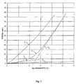
- FIG. 1 Also shown in this FIG. 1 the tangents to the curve 1 of the hybrid cable gimped according to the invention, on the one hand, for a zero elongation (tangent T i ) and, on the other hand, for an elongation corresponding to the rupture of the cable (tangent T R ). These tangents intersect at a transition point corresponding to an elongation of the cable of about 2.5%.
- the extended module of the gimped hybrid cable corresponds substantially to that of the core that it comprises (see FIG. the similar slopes of characteristics 1 and 3 with low elongation), which results in a reduced rolling noise, when this cable is used as reinforcing element of a shrink web of a tire.
- the extended module of the hybrid cable guiped substantially corresponds to that of the guipe it comprises (see Figure 1 similar slopes of characteristics 1 and 2 with high elongation), which results in a satisfying hooping function of the crown ply reinforced by these cables.
- each of these tires comprises two crossed reinforcing plies each comprising 6.23 non-shrunk metal cables at a pitch of 1.5 mm, as well as a hooping crown ply comprising cables oriented in the circumferential direction of the tire.
- the cables of this crown hoop are made of polyamide 6.6 (conventional solution of "high performance" tire binding).
- this sheet is arranged in two superposed layers by a spiral winding technique of a strip of cables embedded in rubber. The density of these cables is 200 cables per dm.
- the cables of this crown hoop are made of aramid.
- This sheet is arranged in a single layer with a cable density of 50 cables per dm.
- the cables of this crown hoop are constituted by hybrid cables gimped according to the invention manufactured according to the embodiment example above (based on an aramid yoke wound helically on a core polyamide 6,6).
- This sheet is also arranged in a single layer with a cable density of 50 cables per dm.
- Tables 1 and 2 below show the results obtained. ⁇ u> Table 1: ⁇ / u> pneumatic Summit tablecloth Tablecloth density ° (cables / dm) Case hum Trackside noise Contact Resistance to speed AT Polyamide 6.6 Bi-layer - 200 reference reference reference 100 VS Guiped hybrids Single layer - 50 -0.4 dB (A) equal to reference -0.5 pts 110
- This table 1 shows that the gimped hybrid cables used in the hooping crown ply give the tires C according to the invention, compared to the "control" tires A incorporating polyamide 6.6 cables in the hooping crown ply, an improvement speed resistance and a reduction in "box hum” and “contact” noise, despite the lower cable density than that used in these "control” tires.
- This table 2 shows that, considering the tire B as "control”, the gimped hybrid cables give the tire C according to the invention a strong reduction of noise "edge of the track", without the resistance to speed is penalized.
- Second series of rolling tests of a vehicle equipped with touring tires the top of which comprises two crossed crown reinforcement plies, two other reinforcement top plies and a hoop top ply.
- each of these tires comprises two crossed reinforcing plies each comprising metallic cables 2.23 not shrunk in 0.7 mm pitch, two other reinforcing crown plies each comprising metal cables 4.23 not shrunk at a pitch of 1.25 mm, and a hooping crown ply having cables oriented in the circumferential direction of the tire.
- the cables of this crown hoop are made of polyamide 6.6.
- This sheet is arranged in two superposed layers by a spiral winding technique of a strip of cables embedded in rubber. The density of these cables is 200 cables per dm.
- the cables of this crown hoop are constituted by hybrid cables gimped according to the embodiment of the invention above (based on an aramid sleeve wound helically on a web polyamide 6,6).
- This sheet is arranged in a single layer with a cable density of 50 cables per dm.
- Table 3 below presents the results obtained for drift rigidity, "box hum” (abbreviated below) and "contact” tests.
- This table 3 shows that the gimped hybrid cables used in the hooping crown ply give the tires E according to the invention a greatly improved drift rigidity as well as reduced “box hum” and “contact” noise compared with the tires. Witness.
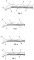
- Fig. 2 shows an axial half-section of a tire P according to the invention, which comprises an apex 4 extended by two flanks 5 and two beads (not shown).
- the top 4 comprises a carcass ply 6 anchored in a known manner in the two beads, two reinforcing plies 7 and 8 formed of parallel cables in each ply and crossed from one ply to the next ply making angles ( ⁇ with the circumferential direction). , ⁇ ) of the order of 30 degrees, and a hooping crown ply 9 comprising the hybrid cables gimped according to the invention.
- These gimped hybrid cables are spirally wound to ensure a good hooping of the crown 4, and they are oriented in the circumferential direction of the tire P.
- the carcass ply 6 is of radial type, being oriented substantially at 90 degrees relative to this circumferential direction.
- Fig. 3 shows a partial axial half-section of a tire P 'comprising, as previously, a carcass ply 6, two crossed reinforcing plies 7, 8, and a hooping crown ply 9 which is arranged radially between the carcass ply 6 and both
- This arrangement has the advantage of protecting the hooping crown ply 9 from any damage caused by perforations of the tread.
- Fig. 4 shows a partial axial half-section of a tire P "comprising, as before, a carcass ply 6, two crossed reinforcing plies 7, 8, and a hooping crown ply 9 which is disposed between the two crossed reinforcing plies 7 and 8.
- Fig. 5 shows a partial axial half-section of a tire P "'comprising, as before, a carcass ply 6, two crossed reinforcing plies 7, 8, and a hooping crown ply 9 arranged radially inside the carcass ply 6 .
- the hybrid cables covered by the invention give the tires P, P ', P "or P'" whose hooping crown ply 9 incorporates these cables the abovementioned advantages of reduction of rolling noise at reduced speed and of hooping. satisfactory at high speed.
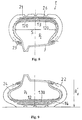
- Figs. 6 and 7 show a mounted assembly E according to the invention for heavy vehicle comprising a tire P, a mounting rim J and a support membrane M.
- the tire P conventionally comprises flanks 20 joined radially on the outside to a tread 21, and radially extended inside by two beads 22, each bead being reinforced by at least one rod 23 around which is anchored a radial carcass reinforcement 24 to form overturns 25.
- the carcass reinforcement 24 is radially surmounted in the crown by a crown reinforcement 26, composed of at least two plies of wires or metallic cables parallel to each other in each ply and crossed from one sheet to the next by making with the circumferential direction of the tire P an angle which can be between 5 ° and 45 °.
- the tire P is said to be chamberless, and comprises an inner layer made of a rubber composition impermeable to inflation gases.
- the tire assembly P and rim J defines a first internal cavity 27 sealed.
- the pneumatic support membrane M defines inside the first cavity 27 a second sealed cavity 15.
- This membrane M is closed, has flanks 11 and is reinforced at its apex by a crown reinforcement 12.
- the latter easily expandable, is associated with a hooping reinforcement 13 composed for example of a crimp top 130 of cables circumferentially oriented.
- these circumferential cords of the hooping crown ply 130 are hybrid cords wrapped according to the invention, for example consisting of an aramid yarn spirally wound on a polyamide core 6.6.
- These gimped hybrid cables allow the ply 130 to provide a satisfactory shrinking function of the membrane M, on the one hand, against the forces due to the centrifugal force and, on the other hand, against the forces due to the pressure differential p 0 - p 1 , p 0 being the inflation pressure in the cavity 15 of the support membrane M, equal for example to 9.5 ⁇ 10 5 Pa, and p 1 being the pressure in the cavity 27 of the tire P equals, for example at 9,0.10 5 Pa.
- These inflation values are the cold nominal values in the example chosen.
- This shrinking function allows the membrane M to maintain, under the normal running conditions of the mounted assembly E, that is to say under the conditions of load, pressure and speed recommended for the tire P concerned, a radius R M substantially constant and less than the crushed radius R E of the tire P (Fig. 7 shows the crushed portion of the assembled assembly E under normal driving conditions).
- the membrane M is completed by the covering of the hooping frame 13, by a rubber layer 14 of small thickness.
- the mounted assembly E operates under a lower pressure p 2 , leading to a crushed radius R ' E running in degraded mode less than the crushed radius R E in normal driving (see Fig. 9).
- the radius R ' E allows a moderate speed taxi to the next maintenance area without major degradation of the tire P and without human intervention, maintenance area where it is then possible to provide the additional pressure necessary to obtain a radius very close to the radius R E and allow rolling under almost normal conditions.
Abstract
Description
La présente invention concerne des câbles hybrides, un procédé pour leur obtention et un tissu composite utilisable dans un pneumatique qui incorpore lesdits câbles. L'invention concerne également un pneumatique et un ensemble monté qui incorporent chacun un tel tissu composite.The present invention relates to hybrid cables, a method for obtaining them and a composite fabric usable in a tire which incorporates said cables. The invention also relates to a tire and a mounted assembly that each incorporate such a composite fabric.
Le développement des pneumatiques destinés à équiper des véhicules de tourisme de type roulant à des vitesses élevées a suscité la mise au point d'architectures toujours plus performantes pour ces pneumatiques.The development of tires intended to equip passenger vehicles of the rolling type at high speeds has led to the development of increasingly efficient architectures for these tires.
Une solution classiquement utilisée pour ces architectures de pneumatiques « haute vitesse » consiste à couvrir les nappes sommet de travail de ces pneumatiques, qui comportent des éléments de renforcement métalliques ou textiles, par une nappe sommet dite de frettage, usuellement renforcée par des câbles textiles. Cette nappe sommet de frettage, qui est par exemple disposée radialement à l'extérieur de l'armature de sommet du pneumatique, est notamment caractérisée en ce que les câbles qui la renforcent sont disposés en spirale selon un angle de 0° ou proche de 0° avec le plan circonférentiel médian du pneumatique. Il est également connu de disposer des bandelelettes ou des nappes relativement étroites selon un angle d'environ 0° à la place des câbles précités, pour remplir une fonction de frettage de l'armature de sommet.A solution conventionally used for these "high speed" tire architectures consists in covering the working crown plies of these tires, which comprise metal or textile reinforcing elements, by a so-called hooping top ply, usually reinforced by textile cables. This crowning crown ply, which is for example arranged radially outside the crown reinforcement of the tire, is characterized in that the cables which reinforce it are arranged in a spiral at an angle of 0 ° or close to 0. ° with the median circumferential plane of the tire. It is also known to have strips or relatively narrow plies at an angle of about 0 ° in place of the aforementioned cables, to fulfill a fretting function of the crown reinforcement.
A titre de câbles textiles pour nappe sommet de frettage, on a testé par le passé des câbles hybrides de type retors, qui sont constitués de deux fils à base de matériaux respectivement de bas et haut modules initiaux qui sont tordus ensemble, en vue de conférer au câble ainsi obtenu un module en extension réduit à faible déformation et au contraire élevé à forte déformation. Ce découplage des modules en extension du câble se traduit par la présence d'un point de transition sur la courbe force-allongement dudit câble, et il est par exemple obtenu en utilisant un polyamide 6,6 pour le matériau de bas module et de l'aramide pour celui de haut module initial.As textile cords for hoop crown ply, hybrid cords of the plied type have been tested in the past, which consist of two yarns based on materials respectively of initial low and high moduli which are twisted together, in order to confer to the cable thus obtained a module in reduced extension with low deformation and on the contrary high with high deformation. This decoupling of the modules in extension of the cable results in the presence of a transition point on the force-elongation curve of said cable, and it is for example obtained by using a
Pour la description de tels câbles hybrides, on pourra se référer au document de brevet américain US-A-3 977 172 et au compte-rendu de la conférence Kautschuk + Gummi Kunststoffe, vol. 40, n° 2, février 1987, pages 130-135, à Heidelberg (Allemagne), E. R. Barron, intitulée « hybrid tire cords containing kevlar® aramid ».For the description of such hybrid cables, reference may be made to US patent document US-A-3,977,172 and the proceedings of the Kautschuk + Gummi Kunststoffe conference, vol. 40, No. 2, February 1987, pages 130-135, in Heidelberg (Germany), ER Barron, entitled "hybrid tire cords containing kevlar® aramid".
Un inconvénient majeur de ces câbles hybrides à structure retordue réside dans la tension de frettage excessive que présente la nappe comportant ces câbles, y compris à des vitesses réduites typiquement inférieures à 120 km/h, (i.e. à des déformations relativement faibles). II résulte de cette tension ou «raidissement» prématuré des câbles un bruit de roulage dû au pneumatique qui est significatif à ces vitesses, ce qui représente une source notable d'inconfort pour les occupants du véhicule.A major disadvantage of these hybrid cables with twisted structure lies in the excessive hooping tension that presents the sheet comprising these cables, including at reduced speeds typically less than 120 km / h, (i.e. relatively small deformations). As a result of this premature voltage or "stiffening" of the cables, a rolling noise due to the tire is significant at these speeds, which represents a significant source of discomfort for the occupants of the vehicle.
Le but de la présente invention est de remédier à cet inconvénient, et il est atteint en ce que les demanderesses viennent d'obtenir d'une manière surprenante des câbles hybrides présentant chacun un rapport (module tangent final/ module tangent initial) supérieur à 10, ce qui permet par exemple de renforcer une nappe sommet de frettage d'un pneumatique de telle manière que :
- à des déformations réduites inhérentes à une vitesse de roulage inférieure à 100 ou 120 km/h, la nappe sommet de frettage engendre un bruit de roulage réduit, et que
- à des déformations élevées inhérentes à une vitesse de roulage typiquement supérieure à 120 km/h, cette nappe sommet assure sa fonction de frettage d'une manière satisfaisante.
- at reduced deformations inherent to a driving speed of less than 100 or 120 km / h, the hooping crown ply generates a reduced rolling noise, and that
- at high deformations inherent to a rolling speed typically greater than 120 km / h, this crown ply performs its function of hooping in a satisfactory manner.
On notera que la valeur du rapport (module tangent final/ module tangent initial) qui caractérise les câbles hybrides selon l'invention est supérieure à celles des mêmes rapports caractérisant les câbles hybrides obtenus à ce jour, qui sont toujours inférieures à 10.It will be noted that the value of the ratio (final tangent modulus / initial tangent modulus) which characterizes the hybrid cables according to the invention is greater than those of the same ratios characterizing the hybrid cables obtained to date, which are always less than 10.
Avantageusement, ce rapport est supérieur à 12 pour les câbles hybrides selon l'invention, et il est par exemple compris entre 12 et 30.Advantageously, this ratio is greater than 12 for the hybrid cables according to the invention, and it is for example between 12 and 30.
On notera que la présente invention n'est nullement limitée à une utilisation en nappe sommet de frettage de ces câbles hybrides, et qu'elle englobe toute utilisation dans des pneumatiques pouvant être de type tourisme ou destinés à porter de lourdes charges, par exemple des pneumatiques poids-lourd, agricole ou de génie civil.It should be noted that the present invention is in no way limited to use in hoop crimping webs of these hybrid cables, and that it encompasses any use in tires which may be of the tourism type or intended to carry heavy loads, for example heavy-duty tires, agricultural or civil engineering.
On notera également que les câbles hybrides selon l'invention permettent d'améliorer l'endurance à vitesse élevée (typiquement supérieure à 120 km/h) de l'armature de sommet de pneumatiques dont la nappe sommet de frettage est renforcée par ces câbles.It will also be noted that the hybrid cables according to the invention make it possible to improve the high speed endurance (typically greater than 120 km / h) of the tire crown reinforcement, the top of which is reinforced by these cables.
Par « câble hybride », on entend dans la présente description un câble composite, i.e. constitué d'au moins deux matériaux de nature et/ou de propriétés différentes.By "hybrid cable" is meant in the present description a composite cable, i.e. consisting of at least two materials of different nature and / or properties.
Par « module tangent initial » du câble hybride selon l'invention, on entend dans la présente description la pente de la tangente à la courbe force/ allongement de ce câble correspondant à un allongement nul.By "initial tangent modulus" of the hybrid cable according to the invention is meant in the present description the slope of the tangent to the force / elongation curve of this cable corresponding to zero elongation.
Par « module tangent final » de ce câble hybride, on entend la pente de la tangente à la courbe force/ allongement dudit câble pour un allongement correspondant à sa rupture.By "final tangent module" of this hybrid cable is meant the slope of the tangent to the force / elongation curve of said cable for an elongation corresponding to its rupture.
On notera que les câbles hybrides selon l'invention présentent chacun une courbe force/ allongement qui est très proche du tracé des tangentes précitées à cette courbe correspondant respectivement à un allongement nul et à la rupture du câble, ce qui se traduit par un découplage des modules tangents dudit câble à faibles et fortes déformations (i.e. à des vitesses de roulage respectivement réduites et élevées).It will be noted that the hybrid cables according to the invention each have a force / elongation curve which is very close to the tracing of the aforementioned tangents to this curve respectively corresponding to a zero elongation and to the breaking of the cable, which results in a decoupling of the tangent modules of said cable at low and high deformations (ie at respectively reduced and high speeds of rolling).
Selon un mode préférentiel de réalisation de l'invention, lesdits câbles hybrides sont de type guipés, comportant une âme textile de module initial inférieur à 900 cN/tex et une guipe textile de module initial supérieur à 1300 cN/tex qui est enroulée sur ladite âme.According to a preferred embodiment of the invention, said hybrid cables are of guiped type, comprising a textile core of initial modulus of less than 900 cN / tex and a textile guipe of initial modulus higher than 1300 cN / tex which is wound on said soul.
Par « module initial » de l'âme ou de la guipe, on entend dans la présente description le module en extension à basse déformation de chacun de ces constituants qui a au préalable été extrait du câble hybride guipé. Ce module initial est défini comme étant la pente de la partie linéaire de la courbe force/ allongement de l'âme ou de la guipe à l'état écru, mesurée juste après une prétension standard de 0,5 cN/tex.By "initial module" of the core or the guipe is meant in the present description the low-strain extension module of each of these components which has previously been extracted hybrid cable guiped. This initial modulus is defined as the slope of the linear part of the force / elongation curve of the unrefined core or web, measured just after a standard pretension of 0.5 cN / tex.
Lesdits modules initiaux et lesdits modules tangents, ainsi que l'ensemble des propriétés mécaniques en extension mentionnées dans la présente description (ténacité, allongement à la rupture, notamment) sont mesurés de manière connue au moyen de mesures de type force (daN)/ allongement (%), réalisées au moyen d'une machine « INSTRON » avec pinces « 4D » et en utilisant les paramètres opératoires suivants :
- longueur de traction : 400 mm,
- vitesse de traction : 200 mm/min,
- prétension standard : 0,5 cN/tex.
- pulling length: 400 mm,
- pulling speed: 200 mm / min,
- standard pretension: 0.5 cN / tex.
Par câble guipé, on entend par définition dans la présente description une âme « droite » sur laquelle est enroulée une guipe, par exemple en hélice. On pourra par exemple se reporter aux documents de brevet américains US-A-4 343 343 et US-A-4 893 665 pour la description de câbles guipés répondant à cette définition.By gimped cable, is meant by definition in the present description a "straight" soul on which is wound a guipe, for example helically. For example, reference may be made to US patent documents US-A-4,343,343 and US-A-4,893,665 for the description of gimped cables meeting this definition.
Par l'expression « âme droite » (usuellement désignée en Anglais par le terme « core » ou core yarn »), on entend un fil unique ou plusieurs fils tordus ensemble sur laquelle vient s'enrouler la guipe (souvent désignée en Anglais par le terme « sheath » ou « sheath yarn »), laquelle est également constituée d'un fil unique ou de plusieurs fils tordus ensemble. L'assemblage de la guipe sur l'âme est donc réalisé sans opération de retordage de ces deux constituants, à la différence des câbles à structure retordue précités.By the expression "right soul" (usually referred to in English as "core" or "core yarn") is meant a single thread or several twisted threads together on which the guipe (often referred to in English by term "sheath" or "sheath yarn"), which also consists of a single yarn or several yarns twisted together. The assembly of the guipe on the core is therefore performed without twisting operation of these two components, unlike the above twisted structure cables.
Dans la présente description, le terme « fil » désigne aussi bien un filé à base d'une multitude de filaments élémentaires de faible diamètre qui sont tordus ensemble (par exemple un filé à base d'une centaine de filaments élémentaires présentant chacun un diamètre voisin d'une dizaine de microns), qu'un unique monofilament.In the present description, the term "wire" designates both a yarn based on a multitude of elementary filaments of small diameter which are twisted together (for example a yarn based on one hundred elementary filaments each having a similar diameter about ten microns), a single monofilament.
Par monofilament, on entend un filament unitaire (non tordu par définition) dont le diamètre ou l'épaisseur D (i.e. la plus petite dimension transversale de sa section droite lorsque celle-ci n'est pas circulaire) est au moins égal(e) à 40 µm (titre minimal de 1,7 tex). Cette définition couvre donc aussi bien des monofilaments de forme essentiellement cylindrique (i.e, à section circulaire) que des monofilaments oblongs, de forme aplatie, ou encore des bandelettes ou films d'épaisseur D.Monofilament means a unit filament (not twisted by definition) whose diameter or thickness D (ie the smallest transverse dimension of its cross section when it is not circular) is at least equal. at 40 μm (minimum titre of 1.7 tex). This definition thus covers both monofilaments of substantially cylindrical shape (i.e, circular section) or oblong monofilaments, of flattened shape, or strips or films of thickness D.
Selon un exemple de réalisation dudit mode préférentiel selon l'invention, le câble hybride guipé est tel que ladite âme est constituée d'un filé unique et que ladite guipe est constituée d'un ou de plusieurs filés tordus ensemble, de préférence de deux à quatre filés tordus ensemble. Dans ce cas, on a imposé au filé formant l'âme une torsion de l'ordre de plusieurs dizaines voire plusieurs centaines de tours/mètre, avant de procéder à l'enroulement de la guipe sur ladite âme.According to an exemplary embodiment of said preferred embodiment according to the invention, the hybrid cable guipé is such that said core consists of a single yarn and said guipe consists of one or more yarns twisted together, preferably two to four yarns twisted together. In this case, the yarn forming the core has been subjected to a torsion of the order of several tens or even several hundred revolutions / meter, before proceeding to the winding of the guipe on said core.
Selon un autre exemple de réalisation dudit mode préférentiel selon l'invention, le câble hybride guipé est tel que ladite âme est constituée de plusieurs filés tordus ensemble et que ladite guipe est constituée d'un ou de plusieurs filés tordus ensemble.According to another exemplary embodiment of said preferred embodiment according to the invention, the hybrid cable guipé is such that said core consists of several yarns twisted together and said yoke consists of one or more yarns twisted together.
Selon un autre exemple de réalisation dudit mode préférentiel selon l'invention, le câble hybride guipé est tel que ladite âme est constituée d'un monofilament et que ladite guipe est constituée d'un filé unique ou de plusieurs filés tordus ensemble.According to another exemplary embodiment of said preferred embodiment according to the invention, the hybrid cable guipé is such that said core consists of a monofilament and said guipe consists of a single yarn or several yarns twisted together.
Selon un autre exemple de réalisation dudit mode préférentiel selon l'invention, le câble hybride guipé est tel que ladite âme est constituée d'un filé unique ou de plusieurs filés tordus ensemble et que ladite guipe est constituée d'un monofilament.According to another exemplary embodiment of said preferred embodiment according to the invention, the hybrid cable guipé is such that said core consists of a single yarn or several yarns twisted together and said yoke consists of a monofilament.
Selon un autre exemple de réalisation dudit mode préférentiel selon l'invention, le câble hybride guipé est tel que ladite âme et ladite guipe sont chacune constituées d'un monofilament.According to another exemplary embodiment of said preferred embodiment according to the invention, the hybrid cable guipé is such that said core and said guipe are each made of a monofilament.
Dans la présente description, le titre des filés a été déterminé sur au moins trois échantillons, chacun correspondant à une longueur de 50 m, par pesée de cette longueur de filé. Le titre est donné en tex (poids en g de 1000 m de filé - rappel: 0,111 tex égal à 1 denier).In the present description, the yarn count was determined on at least three samples, each corresponding to a length of 50 m, by weighing this length of yarn. The title is given in tex (weight in g of 1000 m of yarn - booster: 0.111 tex equal to 1 denier).
La ténacité (force-rupture divisée par le titre) et les divers modules d'extension sont indiqués en cN/tex (1 cN/tex = 0, 11 g/den). L'allongement à la rupture est indiqué en %.The tenacity (breaking strength divided by the title) and the various extension modules are indicated in cN / tex (1 cN / tex = 0, 11 g / den). The elongation at break is indicated in%.
A titre non limitatif, l'âme du câble hybride guipé de l'invention peut être constituée :
- d'un polyamide aliphatique, tel qu'un
polyamide - d'un polyester aliphatique, tel que le polyéthylène téréphtalate (PET), le polyéthylène naphtalate (PEN), ou
- de rayonne.
- an aliphatic polyamide, such as a
polyamide - an aliphatic polyester, such as polyethylene terephthalate (PET), polyethylene naphthalate (PEN), or
- of rayon.
La guipe du câble hybride guipé selon l'invention peut être par exemple constituée :
- d'un polyamide aromatique, tel que l'aramide, ou
- d'un polyester aromatique, tel que le polyester commercialisé sous la dénomination « VECTRA », ou encore
- d'une cellulose ou d'un dérivé de cellulose d'origine cristal-liquide à haut module initial (notamment supérieur à 1500 cN/tex), tels que décrits par exemple dans les documents de brevet WO-A-85/05115, WO-A-96/09356, WO-A-97/06294.
- an aromatic polyamide, such as aramid, or
- an aromatic polyester, such as the polyester marketed under the name "VECTRA", or
- a cellulose or a cellulose derivative of crystalline origin with a high initial modulus (in particular greater than 1500 cN / tex), as described for example in patent documents WO-A-85/05115, WO -A-96/09356, WO-A-97/06294.
Selon un exemple de réalisation dudit mode de préférentiel selon l'invention, le câble hybride guipé comporte une âme en polyamide aliphatique, tel qu'un polyamide 6,6, et une guipe en polyamide aromatique, tel que l'aramide, ou en cellulose à haut module d'origine cristal-liquide.According to an exemplary embodiment of said preferred embodiment according to the invention, the wrapped hybrid cable comprises an aliphatic polyamide core, such as a
Selon une autre caractéristique dudit mode préférentiel selon l'invention, le câble hybride guipé est tel que ladite âme présente un allongement à la rupture supérieur à 10 %.According to another characteristic of said preferred embodiment according to the invention, the hybrid cable guipé is such that said core has an elongation at break greater than 10%.
Selon une autre caractéristique dudit mode préférentiel selon l'invention, le câble hybride guipé présente une courbe force (daN)/ allongement (%) présentant un point de transition, en deçà duquel le module en extension du câble est sensiblement égal à celui de l'âme et au-delà duquel le module en extension de ce câble est sensiblement égal à celui de la guipe, ce point de transition correspondant à un allongement compris entre 1 et 7 %, de préférence compris entre 2 et 4 %.According to another feature of said preferred embodiment according to the invention, the hybrid cable covered has a force curve (daN) / elongation (%) having a transition point, below which the extension module of the cable is substantially equal to that of the the core and beyond which the module in extension of this cable is substantially equal to that of the guipe, this transition point corresponding to an elongation of between 1 and 7%, preferably between 2 and 4%.
De manière connue, on appelle « point de transition » (ou point de changement de pente) le point correspondant à l'allongement pour lequel les deux tangentes à allongement nul et à la rupture se croisent.In known manner, the term "transition point" (or point of change of slope) is the point corresponding to the elongation for which the two tangents with zero elongation and rupture intersect.
Le câble hybride guipé selon ledit mode préférentiel de réalisation de l'invention est obtenu par un procédé consistant essentiellement à :
- obtenir séparément une âme et une guipe formées chacune d'un fil unique ou de plusieurs fils tordus ensemble, puis
- à enrouler, par exemple en hélice, la guipe sur l'âme, de telle sorte que le pas de torsion de l'âme dans le câble guipé soit supérieur à celui de la guipe.
- separately obtain a soul and a guipe each formed of a single thread or several threads twisted together, then
- winding, for example helically, the guipe on the soul, so that the pitch of torsion of the core in the wrapped cable is greater than that of the guipe.
Cet assemblage est par exemple réalisé au moyen d'un dispositif de câblage volumétrique et d'un métier de type à anneaux.This assembly is for example carried out by means of a volumetric wiring device and a ring type loom.
Un tissu composite selon l'invention comporte une composition de caoutchouc à base d'au moins un élastomère diénique qui est renforcée par lesdits câbles hybrides selon l'invention (i.e. présentant chacun un rapport (module tangent final/ module tangent initial) supérieur à 10), et ce tissu composite est utilisable avantageusement dans un pneumatique.A composite fabric according to the invention comprises a rubber composition based on at least one diene elastomer which is reinforced by said hybrid cables according to the invention (ie each having a ratio (final tangent modulus / initial tangent modulus) greater than 10 ), and this composite fabric can be used advantageously in a tire.
Par élastomère diénique, on entend de manière connue un élastomère issu au moins en partie (i.e. un homopolymère ou un copolymère) de monomères diènes c'est-à-dire de monomères porteurs de deux doubles liaisons carbone-carbone, conjuguées ou non.By diene elastomer is meant in known manner an elastomer derived at least in part (ie a homopolymer or a copolymer) of monomers dienes that is to say monomers carrying two carbon-carbon double bonds, conjugated or otherwise.
De préférence, cette composition de caoutchouc est à base d'au moins un élastomère diénique dont le taux molaire d'unités issues de diènes conjugués est supérieur à 15 % (un tel élastomère diénique est communément dit « essentiellement insaturé »).Preferably, this rubber composition is based on at least one diene elastomer whose molar content of units derived from conjugated dienes is greater than 15% (such a diene elastomer is commonly called "essentially unsaturated").
C'est ainsi, par exemple, que des élastomères diéniques tels que les caoutchoucs butyle ou les copolymères de diènes et d'alpha-oléfines de type EPDM n'entrent pas dans la définition précédente et peuvent être qualifiés d'élastomères diéniques "essentiellement saturés" (taux molaire d'unités issues de diènes toujours inférieur à 15 %).Thus, for example, diene elastomers such as butyl rubbers or copolymers of dienes and alpha-olefins of the EPDM type do not fall within the above definition and may be termed "essentially saturated" diene elastomers. "(molar rate of units derived from dienes always less than 15%).
A titre encore plus préférentiel, cette composition de caoutchouc est à base d'au moins un élastomère diénique dont le taux molaire d'unités issues de diènes conjugués est supérieur à 50 % (un tel élastomère diénique est communément appelé "fortement insaturé"). Cet élastomère diénique est alors préférentiellement choisi dans le groupe constitué par les polybutadiènes, le caoutchouc naturel, les polyisoprènes de synthèse, les différents copolymères de butadiène, les différents copolymères d'isoprène, et les mélanges de ces élastomères.Even more preferably, this rubber composition is based on at least one diene elastomer whose molar content of units derived from conjugated dienes is greater than 50% (such a diene elastomer is commonly called "highly unsaturated"). This diene elastomer is then preferably selected from the group consisting of polybutadienes, natural rubber, synthetic polyisoprenes, the various butadiene copolymers, the various isoprene copolymers, and mixtures of these elastomers.
Parmi les polybutadiènes, conviennent en particulier ceux ayant une teneur en unités - 1,2 comprise entre 4% et 80% ou ceux ayant une teneur en cis-1,4 supérieure à 80%.Particularly suitable polybutadienes are those having a 1,2-unit content of between 4% and 80% or those having a cis-1,4 content of greater than 80%.
Parmi les polyisoprènes de synthèse, conviennent en particulier les cis-1,4-polyisoprènes, de préférence ceux ayant un taux de liaisons cis-1,4 supérieur à 90%.Of the synthetic polyisoprenes, cis-1,4-polyisoprenes are particularly suitable, preferably those having a cis-1,4 bond ratio greater than 90%.
Parmi les copolymères de butadiène ou d'isoprène, on entend en particulier les copolymères obtenus par copolymérisation d'au moins l'un de ces deux monomères avec un ou plusieurs composés vinylaromatique ayant de 8 à 20 atomes de carbone. A titre de composés vinylaromatiques conviennent par exemple le styrène, l'ortho-, méta-, para-méthylstyrène, le mélange commercial "vinyle-toluène", le para-tertiobutylstyrène, les méthoxystyrènes, les chlorostyrènes, le vinylmésitylène, le divinylbenzène, le vinylnaphtalène. Les copolymères peuvent contenir entre 99% et 20% en poids d'unités diéniques et entre 1% et 80% en poids d'unités vinylaromatiques.Among the copolymers of butadiene or isoprene, is meant in particular the copolymers obtained by copolymerization of at least one of these two monomers with one or more vinylaromatic compounds having from 8 to 20 carbon atoms. Suitable vinylaromatic compounds are, for example, styrene, ortho-, meta-, para-methylstyrene, the commercial "vinyl-toluene" mixture, para-tert-butylstyrene, methoxystyrenes, chlorostyrenes, vinylmesitylene, divinylbenzene, vinylnaphthalene. The copolymers may contain between 99% and 20% by weight of diene units and between 1% and 80% by weight of vinylaromatic units.
Parmi les copolymères de butadiène ou d'isoprène ci-dessus, on citera préférentiellement les copolymères de butadiène-styrène, les copolymères d'isoprène-butadiène, les copolymères d'isoprène-styrène ou les copolymères d'isoprène-butadiène-styrène.Among the butadiene or isoprene copolymers above, mention will preferably be made of butadiene-styrene copolymers, isoprene-butadiene copolymers, isoprene-styrene copolymers or isoprene-butadiene-styrene copolymers.
En résumé, convient de préférence un élastomère diénique choisi dans le groupe des élastomères diéniques « fortement insaturés » constitué par les polybutadiènes (BR), le caoutchouc naturel (NR), les polyisoprènes de synthèse (IR), les copolymères de butadiène-styrène (SBR), les copolymères d'isoprène-butadiène (BIR), les copolymères d'isoprène-styrène (SIR), les copolymères de butadiène-styrène-isoprène (SBIR) et les mélanges de ces élastomères.In summary, a diene elastomer chosen from the group of "highly unsaturated" diene elastomers consisting of polybutadienes (BR), natural rubber (NR), synthetic polyisoprenes (IR) and butadiene-styrene copolymers ( SBR), isoprene-butadiene copolymers (BIR), isoprene-styrene copolymers (SIR), butadiene-styrene-isoprene copolymers (SBIR) and mixtures of these elastomers.
Avantageusement, la composition de caoutchouc du tissu composite selon l'invention comprend à titre majoritaire (i.e. selon une fraction massique supérieure à 50 %) ou en totalité un ou plusieurs élastomères diéniques « fortement insaturés » tels que définis ci-dessus, éventuellement en association avec un ou plusieurs élastomères diéniques « essentiellement saturés » ou non diéniques utilisés à titre minoritaire, et/ou en association avec des polymères autres que des élastomères (par exemple des polymères thermoplastiques) également utilisés à titre minoritaire.Advantageously, the rubber composition of the composite fabric according to the invention comprises predominantly (ie in a mass fraction greater than 50%) or in all one or more "highly unsaturated" diene elastomers as defined above, optionally in combination with one or more "essentially saturated" or non-dienic diene elastomers used in a minority capacity, and / or in combination with polymers other than elastomers (for example thermoplastic polymers) also used in a minority capacity.
Les compositions de caoutchouc des tissus composites conformes à l'invention comportent également tout ou partie des additifs habituellement utilisés dans la fabrication de pneumatiques, tels que des charges renforçantes comme le noir de carbone ou la silice, des agents anti-vieillissement, par exemple des antioxydants, des huiles d'extension, des plastifiants ou des agents facilitant la mise en oeuvre des compositions à l'état cru, un système de réticulation à base soit de soufre, soit de donneurs de soufre et/ou de peroxyde, des accélérateurs, des activateurs ou retardateurs de vulcanisation, des accepteurs et donneurs de méthylène, des résines, des systèmes promoteurs d'adhésion connus du type "RFS" (résorcinol-formaldéhyde-silice) ou sels métalliques, notamment sels de cobalt.The rubber compositions of the composite fabrics according to the invention also comprise all or part of the additives normally used in the manufacture of tires, such as reinforcing fillers such as carbon black or silica, anti-aging agents, for example antioxidants, extension oils, plasticizers or agents facilitating the use of the compositions in the green state, a crosslinking system based on either sulfur, or sulfur and / or peroxide donors, accelerators, activators or vulcanization retarders, acceptors and donors of methylene, resins, known adhesion promoter systems of the "RFS" type (resorcinol-formaldehyde-silica) or metal salts, especially cobalt salts.
Le tissu composite selon l'invention peut se présenter sous des formes variées, par exemple sous la forme d'une nappe, d'une bande, bandelette ou d'un bloc de caoutchouc dans lequel est incorporé le renfort métallique à l'aide de différents moyens connus de l'homme du métier, tels que par exemple des moyens de moulage, de calandrage ou de boudinage.The composite fabric according to the invention can be in various forms, for example in the form of a sheet, a strip, a strip or a rubber block in which the metal reinforcement is incorporated by means of various means known to those skilled in the art, such as, for example, molding, calendering or extrusion means.
Un pneumatique selon un premier mode de réalisation de la présente invention comporte un sommet qui est prolongé par deux flancs et deux bourrelets et qui comporte une nappe carcasse ancrée dans lesdits bourrelets, ledit sommet comportant :
- au moins une nappe sommet de renforcement comportant des câbles parallèles qui sont orientés par rapport à la direction circonférentielle d'un angle α compris entre 10 et 45 degrés, et
- au moins une nappe sommet de frettage comportant des câbles orientés selon ladite direction circonférentielle qui sont enroulés en spirale,
et ce pneumatique est tel que ladite nappe sommet de frettage est constituée du tissu composite selon l'invention tel que défini précédemment.A tire according to a first embodiment of the present invention comprises a crown which is extended by two flanks and two beads and which comprises a carcass ply anchored in said beads, said crown comprising:
- at least one reinforcing crown ply having parallel ropes which are oriented with respect to the circumferential direction by an angle α of between 10 and 45 degrees, and
- at least one fretted crown ply having cables oriented in said circumferential direction which are spirally wound,
and this tire is such that said hooping crown ply consists of the composite fabric according to the invention as defined above.
Selon un exemple de réalisation de ce premier mode selon l'invention, ce pneumatique est tel que ladite nappe sommet de frettage est disposée radialement à l'extérieur de ladite ou desdites nappes sommet de renforcement.According to an exemplary embodiment of this first embodiment according to the invention, this tire is such that said hooping crown ply is disposed radially outside said reinforcing crown ply or plies.
Selon un autre exemple de réalisation de ce premier mode selon l'invention, ce pneumatique est tel que ladite nappe sommet de frettage est disposée radialement à l'intérieur de ladite nappe carcasse.According to another exemplary embodiment of this first embodiment according to the invention, this tire is such that said hooping crown ply is disposed radially inside said carcass ply.
Selon un autre exemple de réalisation de ce premier mode selon l'invention, ce pneumatique est tel que ledit sommet comporte au moins deux nappes sommet de renforcement superposées comportant chacune des câbles parallèles qui sont croisés d'une nappe à l'autre en faisant avec ladite direction circonférentielle des angles (α, β) compris entre 10 et 45 degrés, et que ladite nappe sommet de frettage est disposée entre lesdites nappes sommet de renforcement.According to another exemplary embodiment of this first embodiment according to the invention, this tire is such that said crown comprises at least two superimposed reinforcing crown plies each comprising parallel cables which are crossed from one ply to the other by making with said circumferential direction of angles (α, β) between 10 and 45 degrees, and said hooping crown ply is disposed between said reinforcing top plies.
Selon un autre exemple de réalisation de ce premier mode selon l'invention, ce pneumatique est tel que ledit sommet comporte au moins deux nappes sommet de renforcement superposées comportant chacune des câbles parallèles qui sont croisés d'une nappe à l'autre en faisant avec ladite direction circonférentielle des angles (α, β) compris entre 10 et 45 degrés, et tel que ladite nappe sommet de frettage est disposée entre ladite nappe carcasse et la nappe sommet de renforcement qui est disposée le plus radialement à l'intérieur.According to another exemplary embodiment of this first embodiment according to the invention, this tire is such that said crown comprises at least two superimposed reinforcing crown plies each comprising parallel cables which are crossed from one ply to the other by making with said circumferential direction of the angles (α, β) between 10 and 45 degrees, and such that said hooping crown ply is disposed between said carcass ply and the reinforcing crown ply which is disposed the most radially inside.
En référence à l'un quelconque de ces exemples de réalisation dudit premier mode selon l'invention, ledit pneumatique est avantageusement tel que, sur toute sa largeur, les câbles hybrides de ladite nappe sommet de frettage présentent un potentiel de contraction à chaud (CS), à l'état vulcanisé et neuf dudit pneumatique, qui est inférieur ou égal au potentiel de contraction à chaud de ces mêmes câbles adhérisés avant leur incorporation dans ladite nappe sommet de frettage.With reference to any one of these embodiments of said first mode according to the invention, said tire is advantageously such that, over its entire width, the hybrid cables of said hooping crown ply have a hot contraction potential (CS ), in the vulcanized and new state of said tire, which is less than or equal to the potential heat shrinking these same adhesive cables prior to their incorporation into said hooping crown web.
Les demanderesses ont constaté que cette caractéristique de potentiel de contraction à chaud des câbles hybrides de la nappe sommet de frettage permet de réduire d'une manière encore plus marquée le bruit de roulement du pneumatique à vitesse réduite, tout en lui conférant un haut niveau de résistance à haute vitesse.The applicants have found that this characteristic of the hot contraction potential of the hybrid cables of the hooping crown ply makes it possible to reduce even more markedly the rolling noise of the tire at a reduced speed, while conferring on it a high level of high speed resistance.
Les câbles hybrides posés circonférentiellement avec des diamètres de pose s'écartant, sur toute la largeur du sommet, de moins de 0,5 % des diamètres finaux de ces câbles dans le pneumatique après vulcanisation, ne subissent au cours de la confection du pneumatique ou de sa vulcanisation aucune opération de conformation notable. Une telle conformation notable entraînerait par exemple, lors de la confection ou de la vulcanisation, une extension locale de ces câbles supérieure à 2 ou 3 %. Cette extension affecte généralement les propriétés des câbles ainsi déformés, notamment leur module, leur potentiel de contraction et leur état de tension.Hybrid cables placed circumferentially with laying diameters deviating, over the entire width of the crown, from less than 0.5% of the final diameters of these cables in the tire after vulcanization, do not undergo during the manufacture of the tire or its vulcanization no significant conformation operation. Such a noticeable conformation would entail, for example, during the manufacture or vulcanization, a local extension of these cables greater than 2 or 3%. This extension generally affects the properties of the cables thus deformed, in particular their modulus, their contraction potential and their state of tension.
II en résulte que les câbles hybrides utilisés sont, dans le pneumatique vulcanisé et sur l'ensemble de la nappe, dans un état très proche de celui des câbles adhérisés avant leur mise en pneumatique.As a result, the hybrid cables used are, in the vulcanized tire and on the entire web, in a state very close to that of the adhered cables before they are placed in a tire.
On entend par « câbles adhérisés » des câbles ayant subi un traitement d'enduction approprié, dit d'encollage ou d'adhérisation, susceptible de les faire adhérer, après un traitement thermique approprié, à la composition de caoutchouc précitée. Les câbles sont encollés en une succession d'étapes par passage dans des bains de colle typiques de l'état de l'art, et traité thermiquement sous une tension permettant de leur conférer le niveau de potentiel de contraction (CS) requis.The term "adhesive cables" means cables having undergone a suitable coating treatment, called sizing or adhesion, capable of adhering, after an appropriate heat treatment, to the aforementioned rubber composition. The cables are glued in a series of steps by passing through glue baths typical of the state of the art, and thermally treated under tension to give them the required level of contraction potential (CS).
On entend par « potentiel de contraction à chaud » (CS), la variation relative de longueur d'un renfort textile positionné, sous une prétension égale à la demi-somme des titres de chacun des brins élémentaires, entre les plateaux d'un four (appareil du type TESTRITE) régulé à une température constante de 185 ± 0,5° C. Ce potentiel est exprimé en % par la formule suivante : CS (%) = 100 × | L1 - L0 | /L0 où L0 est la longueur initiale du renfort adhérisé, à la température ambiante sous une prétension égale à la demi somme des titres de chacun des brins élémentaires et L1 la longueur de ce même renfort à 185° C. La longueur L1 est mesurée au bout d'une durée de stabilisation du renfort à la température de 185° C, égale à 120 s ± 2 %. L'écart type sur la mesure de CS est de ± 0,15 %.By "hot contraction potential" (CS) is meant the relative variation in length of a textile reinforcement positioned under a pretension equal to the half-sum of the titles of each of the elementary strands, between the trays of an oven (device of the TESTRITE type) regulated at a constant temperature of 185 ± 0.5 ° C. This potential is expressed in% by the following formula: CS (%) = 100 × | L 1 - L 0 | / L 0 where L 0 is the initial length of the reinforcement adhered at room temperature under a pretension equal to half the sum of the titles of each of the elementary strands and L 1 the length of this same reinforcement at 185 ° C. The length L 1 is measured after a period of stabilization of the reinforcement at the temperature of 185 ° C, equal to 120 s ± 2%. The standard deviation on the CS measurement is ± 0.15%.
Ce potentiel est directement la conséquence de l'ensemble des opérations que le renfort a subi lors de son élaboration ou lors de sa mise en oeuvre.This potential is directly the consequence of all the operations that the reinforcement has undergone during its elaboration or during its implementation.
Le potentiel de contraction à chaud des câbles hybrides selon l'invention avant leur incorporation dans le pneumatique est préférentiellement supérieur à 0,5 % et encore plus préférentiellement supérieur à 1 %.The hot contraction potential of the hybrid cables according to the invention before their incorporation into the tire is preferably greater than 0.5% and even more preferably greater than 1%.
Après vulcanisation d'un pneumatique selon l'invention, on a réalisé une extraction de plusieurs tronçons de câbles hybrides de la nappe sommet de frettage et l'on a mesuré immédiatement (c'est-à-dire que l'intervalle de temps séparant l'extraction des câbles de l'introduction de ces mêmes câbles dans le four du TESTRITE est inférieur à 60 secondes) leur potentiel de contraction à chaud. Ces mesures ont confirmé que la valeur de leur CS est bien inférieure ou égale à celle qu'ils avaient avant leur introduction dans le pneumatique, quelle que soit leur position axiale dans le pneumatique.After vulcanization of a tire according to the invention, an extraction of several hybrid cable sections from the hooping crown ply was measured and measured immediately (i.e. the time interval between the extraction of the cables from the introduction of these same cables into the furnace of the TESTRITE is less than 60 seconds) their contraction potential when hot. These measurements have confirmed that the value of their CS is much lower than or equal to that they had before their introduction into the tire, regardless of their axial position in the tire.
Selon un mode de réalisation selon l'invention, la confection du pneumatique selon l'invention peut avantageusement être réalisée sur un noyau rigide imposant la forme de sa cavité intérieure, tels ceux décrits dans les documents de brevet EP-A-242 840 ou EP-A-822 047. On applique sur ce noyau, dans l'ordre requis par l'architecture finale, tous les constituants du pneumatique, qui sont disposés directement à leur place finale, sans subir de conformation à aucun moment de la confection. La cuisson s'effectue sur noyau, celui-ci n'étant retiré qu'après la phase de vulcanisation.According to one embodiment of the invention, the manufacture of the tire according to the invention can advantageously be carried out on a rigid core imposing the shape of its internal cavity, such as those described in patent documents EP-A-242 840 or EP A-822 047 is applied to this core, in the order required by the final architecture, all the constituents of the tire, which are arranged directly in their final place, without undergoing any conformation at any time of manufacture. The cooking is carried out on a core, the latter being removed only after the vulcanization phase.
Ce mode de fabrication a l'avantage de réduire fortement voire d'éliminer les précontraintes imposées aux câbles, particulièrement aux câbles hybrides orientés à 0°, lors des phases traditionnelles de conformation.This method of manufacture has the advantage of greatly reducing or even eliminating the prestressing imposed on the cables, particularly the hybrid cables oriented at 0 °, during the traditional phases of conformation.
On peut aussi refroidir partiellement le bandage sur le noyau pour maintenir les renforts dans l'état de déformation imposé lors de la pose.It is also possible to partially cool the bandage on the core to maintain the reinforcements in the state of deformation imposed during the laying.
Selon un autre mode de réalisation de l'invention, on peut, d'une manière équivalente, fabriquer le pneumatique sur un tambour tel que décrit dans les documents de brevet WO-A-97/47 463 ou EP-A-718 090, à condition de réaliser la conformation de l'ébauche du pneumatique avant d'effectuer la pose des câbles hybrides orientés circonférentiellement.According to another embodiment of the invention, it is possible, in an equivalent manner, to manufacture the tire on a drum as described in patent documents WO-A-97/47. 463 or EP-A-718 090, provided the conformation of the tire blank before laying the circumferentially oriented hybrid cables.
Selon un autre mode de réalisation selon l'invention, on peut encore réaliser la pose des câbles hybrides sur une forme à la géométrie identique à la forme visée dans le moule de cuisson. Le bloc sommet est ensuite assemblé avec l'ébauche complémentaire du pneumatique suivant des techniques de transfert connues de l'homme de l'art, puis, toujours suivant des principes connus, le pneumatique est emboîté et mis sous pression par déploiement d'une membrane à l'intérieur du pneumatique.According to another embodiment of the invention, it is still possible to lay the hybrid cables on a shape with the same geometry as the target shape in the baking mold. The crown block is then assembled with the complementary blank of the tire according to transfer techniques known to those skilled in the art, then, again according to known principles, the tire is fitted and pressurized by deployment of a membrane. inside the tire.
Ce mode de réalisation garantit aussi l'absence de précontraintes dues à la conformation en presse de vulcanisation.This embodiment also guarantees the absence of prestresses due to the conformation in vulcanization press.
Tous ces modes de réalisation permettent d'obtenir que les câbles hybrides orientés circonférentiellement soient enroulés en spirale avec des diamètres de pose s'écartant, sur toute la largeur du sommet, de moins de 0,5 % des diamètres finaux de ces câbles dans le pneumatique après vulcanisation.All these embodiments make it possible to obtain that the circumferentially oriented hybrid cables are wound in a spiral with laying diameters deviating, over the entire width of the crown, from less than 0.5% of the final diameters of these cables in the pneumatic after vulcanization.
Un ensemble monté selon un exemple de réalisation de l'invention, utilisable pour équiper un véhicule poids-lourd, comporte une jante, un pneumatique monté sur ladite jante et une membrane de soutien qui est montée sur ladite jante à l'intérieur dudit pneumatique et qui est adaptée pour soutenir ledit pneumatique en cas de chute de la pression à l'intérieur de celui-ci, de telle manière que ledit ensemble monté comporte dans son espace interne deux cavités mutuellement étanches qui sont séparées l'une de l'autre par ladite membrane, laquelle est renforcée en son sommet par au moins une nappe sommet de renforcement et par une nappe sommet de frettage, laquelle comporte des câbles orientés selon la direction circonférentielle dudit ensemble monté.An assembly mounted according to an exemplary embodiment of the invention, usable to equip a heavy vehicle, comprises a rim, a tire mounted on said rim and a support membrane which is mounted on said rim inside said tire and which is adapted to support said tire in the event of a drop in pressure therein, such that said mounted assembly has in its internal space two mutually sealed cavities which are separated from each other by said membrane, which is reinforced at its top by at least one reinforcing crown ply and with a crimping crown ply, which comprises cables oriented in the circumferential direction of said mounted assembly.
Cet ensemble monté est tel que ladite nappe sommet de frettage est constituée du tissu composite selon l'invention tel que défini précédemment.This assembled assembly is such that said hooping crown ply consists of the composite fabric according to the invention as defined above.
La cavité interne à cette membrane est destinée à être gonflée à une pression supérieure à celle de la cavité restante du pneumatique. Dans ces conditions usuelles d'utilisation, la membrane a un rayon de roulement au sommet qui est inférieur au rayon écrasé du pneumatique utilisé à sa pression recommandée.The internal cavity of this membrane is intended to be inflated to a pressure greater than that of the remaining cavity of the tire. Under these usual conditions of use, the membrane has a radius of rolling at the top which is less than the crushed radius of the tire used at its recommended pressure.
En cas de crevaison du pneumatique, dès que la différence de pression entre la cavité interne à la membrane et celle du pneumatique dépasse une valeur donnée, la nappe sommet de frettage de la membrane se rompt, entraînant le déploiement de la membrane sous le pneumatique et permettant ainsi à l'ensemble monté de poursuivre son roulage dans des conditions acceptables en mode dégradé. On pourra se reporter au document de brevet WO-A-98/23457 pour une description du fonctionnement général de cet ensemble monté.In the event of a tire puncture, as soon as the pressure difference between the internal cavity of the diaphragm and that of the tire exceeds a given value, the crimping crown ply of the diaphragm breaks, causing the diaphragm to deploy under the tire and thus allowing the mounted assembly to continue driving in acceptable conditions in degraded mode. Reference can be made to patent document WO-A-98/23457 for a description of the general operation of this mounted assembly.
Les caractéristiques précitées de la présente invention, ainsi que d'autres, seront mieux comprises à la lecture de la description suivante de plusieurs exemples de réalisation de l'invention, donnés à titre illustratif et non limitatif, ladite description étant réalisée en référence avec les dessins joints, parmi lesquels :
- La Fig. 1 est un graphique illustrant la caractéristique force-allongement d'un câble hybride guipé selon l'invention,
- la Fig. 2 est une vue en demi-coupe axiale d'un pneumatique comportant une nappe sommet de frettage disposée selon un exemple de réalisation de l'invention,
- la Fig. 3 est une vue en demi-coupe axiale d'un pneumatique comportant une nappe sommet de frettage disposée selon un autre exemple de réalisation de l'invention,
- la Fig. 4 est une vue en demi-coupe axiale d'un pneumatique comportant une nappe sommet de frettage disposée selon un autre exemple de réalisation de l'invention,
- la Fig. 5 est une vue en demi-coupe axiale d'un pneumatique comportant une nappe sommet de frettage disposée selon un autre exemple de réalisation de l'invention,
- les Figs. 6
et 7 représentent respectivement, d'une manière schématique, des sections méridiennes diamétralement opposées d'un ensemble monté comportant une jante, un pneumatique et une membrane de sécurité, lorsque le pneumatique est écrasé sous charge et roule sous des conditions normales, et - les Figs. 8
et 9 représentent respectivement, d'une manière schématique à l'instar des Figs. 6et 7, les sections méridiennes du même ensemble monté qui est soumis à un roulage en mode dégradé.
- Fig. 1 is a graph illustrating the force-elongation characteristic of a hybrid cable gimped according to the invention,
- FIG. 2 is an axial half-sectional view of a tire comprising a hooping crown ply arranged according to an exemplary embodiment of the invention,
- FIG. 3 is an axial half-sectional view of a tire comprising a hooping crown ply arranged according to another exemplary embodiment of the invention,
- FIG. 4 is an axial half-sectional view of a tire comprising a hooping crown ply arranged according to another embodiment of the invention,
- FIG. 5 is an axial half-section view of a tire comprising a hooping crown ply arranged according to another embodiment of the invention,
- Figs. 6 and 7 respectively show schematically diametrically opposed meridian sections of a mounted assembly having a rim, a tire and a safety diaphragm, when the tire is crushed under load and rolls under normal conditions, and
- Figs. 8 and 9 respectively show, in a schematic manner like Figs. 6 and 7, the meridian sections of the same assembled assembly which is subjected to a run in degraded mode.
On a réalisé un câble hybride guipé selon l'invention en réalisant séparément, en sens inverse et selon un même pas de torsion :
- d'une part, un fil tordu sur lui-même (communément appelé « surtors » par l'homme du métier) à base d'un filé en
polyamide - d'autre part, un fil à base de deux filés retordus ensemble (communément appelé « retors » par l'homme du métier) en Kevlar® (aramide), présentant chacun un titre égal à 167 tex, ce fil étant destiné à constituer la guipe dudit câble.
- on the one hand, a wire twisted on itself (commonly called "surtors" by the skilled person) based on a polyamide 6.6 thread of title equal to 94 tex which is intended to constitute the soul cable and,
- on the other hand, a yarn based on two yarns twisted together (commonly called "twists" by those skilled in the art) in Kevlar® (aramid), each having a title equal to 167 tex, this thread being intended to constitute the guipe said cable.
Plus précisément, le filé d'âme est tordu dans le sens S selon un pas de 200 tours/mètre (S200), et les filés de guipe sont tordus ensemble dans le sens Z selon un même pas (Z200).Specifically, the core yarn is twisted in the direction S in a pitch of 200 revolutions / meter (S200), and the yarns of guipe are twisted together in the direction Z in a same step (Z200).
On enroule ensuite en hélice le fil de guipe sur le fil d'âme en imprimant une torsion supplémentaire de 115 tours/mètre, au moyen d'un dispositif de câblage volumétrique et d'un métier de type à anneaux, cette torsion supplémentaire étant réalisée dans le sens de surtorsion (S) de l'âme, de telle manière que le pas de torsion de l'âme dans le câble guipé soit de 315 tours/mètre dans le sens S, et que celui de la guipe dans ledit câble soit de 85 tours/mètre dans le sens Z.The guip yarn is then spirally wrapped around the core wire, imparting an additional twist of 115 revolutions / meter, by means of a volumetric wiring device and a ring-type loom, this additional twist being performed in the direction of overtension (S) of the core, such that the pitch of torsion of the core in the covered cable is 315 turns / meter in the S direction, and that of the guipe in said cable is 85 rpm / meter in the Z direction.
On a ensuite procédé à l'encollage du câble hybride guipé ainsi obtenu, en utilisant une tension de traitement de 0,25 daN.The gimped hybrid cable thus obtained was then glued using a treatment voltage of 0.25 daN.
La Fig. 1 montre la courbe force-allongement obtenue pour ce câble hybride guipé encollé selon l'invention (référence 1 sur cette Fig. 1), en comparaison :
- de la courbe 2 d'un fil de type retors, qui est constitué de deux filés de Kevlar® tordus ensemble (présentant chacun un titre de 167 tex et étant tordus selon un pas de 315 tours/mètre), et
- de la courbe 3 d'un filé en
polyamide 6,6 (présentant un titre de 94 tex et tordu sur lui-même selon un pas de 300 tours/mètre).
-
curve 2 of a twisted yarn, which consists of two yarns of Kevlar® twisted together (each having a title of 167 tex and being twisted in a pitch of 315 revolutions / meter), and - of the
curve 3 of a polyamide 6.6 yarn (having a title of 94 tex and twisted on itself in a pitch of 300 revolutions / meter).
On a représenté également sur cette Fig. 1 les tangentes à la courbe 1 du câble hybride guipé selon l'invention, d'une part, pour un allongement nul (tangente Ti) et, d'autre part, pour un allongement correspondant à la rupture du câble (tangente TR). Ces tangentes se croisent en un point de transition correspondant à un allongement du câble d'environ 2,5 %.Also shown in this FIG. 1 the tangents to the
Le calcul des pentes de ces tangentes Ti et TR donne les modules tangents initiaux et finaux du câble pour un allongement nul et à la rupture, respectivement. On en déduit le rapport (module tangent final / module tangent initial) dudit câble.The calculation of the slopes of these tangents T i and T R gives the initial and final tangent modules of the cable for zero elongation and at break, respectively. We deduce the ratio (final tangent module / initial tangent module) of said cable.
On obtient, pour la tangente TR, une pente d'environ 1,01 daN et, pour la tangente Ti, une pente d'environ 0,078 daN, d'où une valeur de 12,95 pour la valeur du rapport (module tangent final / module tangent initial) du câble hybride guipé selon l'invention.For the tangent T R , a slope of approximately 1.01 daN is obtained and, for the tangent T i , a slope of approximately 0.078 daN, hence a value of 12.95 for the value of the ratio (modulus final tangent / initial tangent module) hybrid cable wrapped according to the invention.
Ce découplage très significatif des modules tangents à faibles et fortes déformations se traduit par le fait que la courbe force-allongement du câble hybride guipé selon l'invention est très proche du tracé des tangentes Ti et TR.This very significant decoupling of tangent modules with small and strong deformations results in the fact that the force-elongation curve of the hybrid cable covered according to the invention is very close to the pattern of tangents T i and T R.
On notera qu'à des déformations réduites inhérentes à une vitesse de roulage inférieure à 120 km/h par exemple, le module en extension du câble hybride guipé correspond sensiblement à celui de l'âme qu'il comporte (voir sur la Fig. 1 les pentes analogues des caractéristiques 1 et 3 à faible allongement), ce qui se traduit par un bruit au roulage réduit, lorsque ce câble est utilisé comme élément de renforcement d'une nappe sommet de frettage d'un pneumatique.It will be noted that at reduced deformations inherent to a running speed of less than 120 km / h, for example, the extended module of the gimped hybrid cable corresponds substantially to that of the core that it comprises (see FIG. the similar slopes of
On notera également qu'à des déformations élevées inhérentes à une vitesse de roulage par exemple supérieure à 120 km/h, le module en extension du câble hybride guipé correspond sensiblement à celui de la guipe qu'il comporte (voir sur la Fig. 1 les pentes analogues des caractéristiques 1 et 2 à allongement élevé), ce qui se traduit par une fonction de frettage satisfaisante de la nappe sommet renforcée par ces câbles.Note also that at high deformations inherent to a driving speed for example greater than 120 km / h, the extended module of the hybrid cable guiped substantially corresponds to that of the guipe it comprises (see Figure 1 similar slopes of
Les deux séries d'essais suivantes permettent d'illustrer les avantages procurés par les câbles hybrides guipés selon l'invention dans des nappes sommet de frettage de pneumatique.The following two series of tests make it possible to illustrate the advantages provided by the hybrid cables wrapped according to the invention in tire hoop crown plies.
Ces essais concernent des pneumatiques A, B et C de dimensions 235/55-17 destinés à équiper des véhicules rapides de type tourisme. Le bloc sommet de chacun de ces pneumatiques comporte deux nappes de renforcement croisées comportant chacune des câbles métalliques 6.23 non frettés au pas de 1,5 mm, ainsi qu'une nappe sommet de frettage comportant des câbles orientés dans la direction circonférentielle du pneumatique.These tests concern tires A, B and C of dimensions 235 / 55-17 intended to equip fast vehicles of the tourism type. The crown block of each of these tires comprises two crossed reinforcing plies each comprising 6.23 non-shrunk metal cables at a pitch of 1.5 mm, as well as a hooping crown ply comprising cables oriented in the circumferential direction of the tire.
Dans le cas des pneumatiques A, les câbles de cette nappe sommet de frettage sont constitués de polyamide 6,6 (solution classique de frettage de pneumatique «haute performance »). Pour obtenir une résistance à la vitesse acceptable, cette nappe est disposée en deux couches superposées par une technique d'enroulement en spirale d'une bande de câbles enrobés dans du caoutchouc. La densité de ces câbles est de 200 câbles par dm.In the case of tires A, the cables of this crown hoop are made of polyamide 6.6 (conventional solution of "high performance" tire binding). To obtain a resistance to the acceptable speed, this sheet is arranged in two superposed layers by a spiral winding technique of a strip of cables embedded in rubber. The density of these cables is 200 cables per dm.
Dans le cas des pneumatiques B, les câbles de cette nappe sommet de frettage sont constitués d'aramide. Cette nappe est disposée en une seule couche avec une densité de câbles de 50 câbles par dm.In the case of tires B, the cables of this crown hoop are made of aramid. This sheet is arranged in a single layer with a cable density of 50 cables per dm.
Dans le cas des pneumatiques C, les câbles de cette nappe sommet de frettage sont constitués des câbles hybrides guipés selon l'invention fabriqués selon l'exemple de réalisation ci-dessus (à base d'une guipe en aramide enroulée en hélice sur une âme en polyamide 6,6). Cette nappe est également disposée en une seule couche avec une densité de câbles de 50 câbles par dm.In the case of tires C, the cables of this crown hoop are constituted by hybrid cables gimped according to the invention manufactured according to the embodiment example above (based on an aramid yoke wound helically on a
Quatre tests ont été réalisés pour chacun de ces pneumatiques A, B et C :
- « bourdonnement de caisse » : ce test est représentatif pour un passager de la gêne acoustique provoquée au passage du véhicule à vitesse constante sur un sol de granulométrie moyenne, de type routier. On fait passer un véhicule à une vitesse donnée sur une aire de mesure normalisée, et des microphones enregistrent le niveau de bruit en dB(A) ;
- bruit « bord de piste » ou « coast by » : ce test est représentatif pour un riverain de la gêne acoustique provoquée au passage du véhicule à vitesse constante sur un sol de granulométrie intermédiaire, de type autoroutier. On fait passer le véhicule à une vitesse donnée, boîte de vitesse au point mort et moteur coupé, sur une aire de mesure normalisée (norme
ISO DIS 10 844), et des microphones enregistrent les niveaux de bruit en dB(A) ; - « contact » : ce test est représentatif pour un passager de la gêne vibratoire et acoustique provoquée au passage du véhicule à vitesse constante sur un obstacle de type plaque d'égout. On fait passer sur cette plaque le véhicule à une vitesse donnée, et l'opérateur apprécie le niveau vibratoire et acoustique puis traduit le gain (-) ou la déchéance (+) sur une échelle de -2 à +2, le pneumatique « témoin » (référence) étant à 0 ;
- résistance à la vitesse : à charge et pression de gonflage données, on augmente progressivement la vitesse du pneumatique jusqu'à la destruction de celui-ci, et le résultat du test est donné par la vitesse maximale atteinte et par l'observation de la cause de la destruction du pneumatique.
- "Body buzz": this test is representative for a passenger of the acoustic discomfort caused by the passage of the vehicle at a constant speed on a medium-grained soil of the road type. A vehicle is run at a given speed over a standard measurement area, and microphones record the noise level in dB (A);
- noise "edge of track" or "coast by": this test is representative for a resident of the acoustic discomfort caused to the passage of the vehicle at constant speed on a ground of intermediate granulometry, motorway type. The vehicle is driven at a specified speed, neutral gearbox and engine off, to a standard measurement area (
ISO DIS 10 844), and microphones record noise levels in dB (A); - "Contact": this test is representative for a passenger of the vibratory and acoustic discomfort caused by the passage of the vehicle at a constant speed over a manhole-type obstacle. This plate is passed over the vehicle at a given speed, and the operator assesses the vibratory and acoustic level and then translates the gain (-) or the decay (+) on a scale of -2 to +2, the tire "control" (Reference) being 0;
- resistance to speed: at given load and inflation pressure, the speed of the tire is gradually increased until it is destroyed, and the result of the test is given by the maximum speed reached and by the observation of the cause the destruction of the tire.
Les tableaux 1 et 2 ci-après présentent les résultats obtenus.
Ce tableau 1 montre que les câbles hybrides guipés utilisés dans la nappe sommet de frettage confèrent aux pneumatiques C selon l'invention, par rapport aux pneumatiques A « témoin » incorporant des câbles de polyamide 6,6 dans la nappe sommet de frettage, une amélioration de la résistance à la vitesse ainsi qu'une réduction du bruit de « bourdonnement de caisse » et de « contact », en dépit de la densité de câbles inférieure à celle utilisée dans ces pneumatiques A « témoin ».This table 1 shows that the gimped hybrid cables used in the hooping crown ply give the tires C according to the invention, compared to the "control" tires A incorporating polyamide 6.6 cables in the hooping crown ply, an improvement speed resistance and a reduction in "box hum" and "contact" noise, despite the lower cable density than that used in these "control" tires.
On notera que ces câbles hybrides guipés ne pénalisent pas le bruit « bord de piste » des pneumatiques C selon l'invention, par rapport à celui des pneumatiques « témoin » A.
Ce tableau 2 montre que, en considérant le pneumatique B comme « témoin », les câbles hybrides guipés confèrent au pneumatique C selon l'invention une forte réduction du bruit « bord de piste », sans que la résistance à la vitesse ne soit pénalisée.This table 2 shows that, considering the tire B as "control", the gimped hybrid cables give the tire C according to the invention a strong reduction of noise "edge of the track", without the resistance to speed is penalized.
Ces essais concernent également des pneumatiques D et E de dimensions 235/55-17 destinés à équiper des véhicules rapides de type tourisme. Le bloc sommet de chacun de ces pneumatiques comporte deux nappes de renforcement croisées comportant chacune des câbles métalliques 2.23 non frettés au pas de 0,7 mm, deux autres nappes sommet de renforcement comportant chacune des câbles métalliques 4.23 non frettés au pas de 1,25 mm, ainsi qu'une nappe sommet de frettage comportant des câbles orientés dans la direction circonférentielle du pneumatique.These tests also concern tires D and E of dimensions 235 / 55-17 intended to equip fast vehicles of the tourism type. The top block of each of these tires comprises two crossed reinforcing plies each comprising metallic cables 2.23 not shrunk in 0.7 mm pitch, two other reinforcing crown plies each comprising metal cables 4.23 not shrunk at a pitch of 1.25 mm, and a hooping crown ply having cables oriented in the circumferential direction of the tire.
Dans le cas des pneumatiques D, les câbles de cette nappe sommet de frettage sont constitués de polyamide 6,6. Cette nappe est disposée en deux couches superposées par une technique d'enroulement en spirale d'une bande de câbles enrobés dans du caoutchouc. La densité de ces câbles est de 200 câbles par dm.In the case of tires D, the cables of this crown hoop are made of polyamide 6.6. This sheet is arranged in two superposed layers by a spiral winding technique of a strip of cables embedded in rubber. The density of these cables is 200 cables per dm.
Dans le cas des pneumatiques E, les câbles de cette nappe sommet de frettage sont constitués des câbles hybrides guipés selon l'exemple de réalisation de l'invention ci-dessus (à base d'une guipe en aramide enroulée en hélice sur une âme en polyamide 6,6). Cette nappe est disposée en une seule couche avec une densité de câbles de 50 câbles par dm.In the case of tires E, the cables of this crown hoop are constituted by hybrid cables gimped according to the embodiment of the invention above (based on an aramid sleeve wound helically on a
Un test supplémentaire a été réalisé pour ces pneumatiques D et E :
- détermination de la rigidité de dérive : à vitesse, pression de gonflage et charge données, on impose un angle de dérive et on mesure la poussée de dérive résultante, le résultat s'exprimant en faisant le rapport poussée de dérive / angle de dérive. La mesure est effectuée d'une manière connue entre ± 1 degré d'angle de dérive.
- determination of drift rigidity: at given speed, inflation pressure and load, a drift angle is imposed and the resulting drift thrust is measured, the result being expressed as the drift / drift angle ratio. The measurement is made in a known manner between ± 1 degree of drift angle.
Le tableau 3 ci-après présente les résultats obtenus pour les tests de rigidité de dérive, de « bourdonnement de caisse » (BdC en abrégé ci-dessous) et de « contact ».
Ce tableau 3 montre que les câbles hybrides guipés utilisés en nappe sommet de frettage confèrent aux pneumatiques E selon l'invention une rigidité de dérive fortement améliorée ainsi que des bruits de « bourdonnement de caisse » et de « contact » réduits, par rapport aux pneumatiques D « témoin ».This table 3 shows that the gimped hybrid cables used in the hooping crown ply give the tires E according to the invention a greatly improved drift rigidity as well as reduced "box hum" and "contact" noise compared with the tires. Witness.
La Fig. 2 présente une demi-coupe axiale d'un pneumatique P selon l'invention, qui comporte un sommet 4 prolongé par deux flancs 5 et deux bourrelets (non représentés).Fig. 2 shows an axial half-section of a tire P according to the invention, which comprises an apex 4 extended by two
Le sommet 4 comporte une nappe carcasse 6 ancrée de façon connue dans les deux bourrelets, deux nappes de renforcement 7 et 8 formées de câbles parallèles dans chaque nappe et croisés d'une nappe à la suivante en faisant avec la direction circonférentielle des angles (α, β) de l'ordre de 30 degrés, et une nappe sommet de frettage 9 comportant les câbles hybrides guipés selon l'invention.The top 4 comprises a
Ces câbles hybrides guipés sont enroulés en spirale pour assurer un bon frettage du sommet 4, et ils sont orientés dans la direction circonférentielle du pneumatique P.These gimped hybrid cables are spirally wound to ensure a good hooping of the
La nappe carcasse 6 est de type radiale, étant orientée sensiblement à 90 degrés relativement à cette direction circonférentielle.The carcass ply 6 is of radial type, being oriented substantially at 90 degrees relative to this circumferential direction.
La Fig. 3 présente une demi-coupe axiale partielle d'un pneumatique P' comportant comme précédemment une nappe carcasse 6, deux nappes de renforcement croisées 7, 8, et une nappe sommet de frettage 9 qui est disposée radialement entre la nappe carcasse 6 et les deux nappes de renforcement croisées 7 et 8. Cette disposition a l'avantage de protéger la nappe sommet de frettage 9 d'éventuels dommages dus à des perforations de la bande de roulement.Fig. 3 shows a partial axial half-section of a tire P 'comprising, as previously, a
La Fig. 4 présente une demi-coupe axiale partielle d'un pneumatique P" comportant comme précédemment une nappe carcasse 6, deux nappes de renforcement croisées 7, 8, et une nappe sommet de frettage 9 qui est disposée entre les deux nappes de renforcement croisées 7 et 8.Fig. 4 shows a partial axial half-section of a tire P "comprising, as before, a
La Fig. 5 présente une demi-coupe axiale partielle d'un pneumatique P"' comportant comme précédemment une nappe carcasse 6, deux nappes de renforcement croisées 7, 8, et une nappe sommet de frettage 9 disposée radialement à l'intérieur de la nappe carcasse 6.Fig. 5 shows a partial axial half-section of a tire P "'comprising, as before, a
On notera que les câbles hybrides guipés selon l'invention confèrent aux pneumatiques P, P', P" ou P'" dont la nappe sommet de frettage 9 incorpore ces câbles les avantages précités de réduction de bruit de roulage à vitesse réduite et de frettage satisfaisant à vitesse élevée.It will be noted that the hybrid cables covered by the invention give the tires P, P ', P "or P'" whose hooping crown ply 9 incorporates these cables the abovementioned advantages of reduction of rolling noise at reduced speed and of hooping. satisfactory at high speed.
Les Figs. 6 et 7 présentent un ensemble monté E selon l'invention pour véhicule poids-lourd comportant un pneumatique P, une jante de montage J et une membrane de soutien M.Figs. 6 and 7 show a mounted assembly E according to the invention for heavy vehicle comprising a tire P, a mounting rim J and a support membrane M.
Le pneumatique P comporte classiquement des flancs 20 réunis radialement à l'extérieur à une bande de roulement 21, et prolongés radialement à l'intérieur par deux bourrelets 22, chaque bourrelet étant renforcé par au moins une tringle 23 autour de laquelle vient s'ancrer une armature de carcasse radiale 24 pour former des retournements 25. L'armature de carcasse 24 est surmontée radialement dans le sommet par une armature de sommet 26, composée d'au moins deux nappes de fils ou câbles métalliques parallèles entre eux dans chaque nappe et croisés d'une nappe à la suivante en faisant avec la direction circonférentielle du pneumatique P un angle pouvant être compris entre 5° et 45°.The tire P conventionally comprises
Le pneumatique P est dit sans chambre, et comprend une couche intérieure constituée d'une composition de caoutchouc imperméable aux gaz de gonflage. L'ensemble pneumatique P et jante J définit une première cavité interne 27 étanche.The tire P is said to be chamberless, and comprises an inner layer made of a rubber composition impermeable to inflation gases. The tire assembly P and rim J defines a first
La membrane de soutien pneumatique M définit à l'intérieur de la première cavité 27 une seconde cavité 15 étanche. Cette membrane M est fermée, comporte des flancs 11 et est renforcée en son sommet par une armature de sommet 12. Cette dernière, facilement expansible, est associée à une armature de frettage 13 composée par exemple d'une nappe sommet de frettage 130 de câbles orientés circonférentiellement.The pneumatic support membrane M defines inside the first cavity 27 a second sealed
Selon l'invention, ces câbles circonférentiels de la nappe sommet de frettage 130 sont des câbles hybrides guipés conformes à l'invention, par exemple constitués d'une guipe en aramide enroulée en hélice sur une âme en polyamide 6,6.According to the invention, these circumferential cords of the hooping crown ply 130 are hybrid cords wrapped according to the invention, for example consisting of an aramid yarn spirally wound on a polyamide core 6.6.
Ces câbles hybrides guipés permettent à la nappe 130 d'assurer une fonction de frettage satisfaisante de la membrane M, d'une part, contre les efforts dus à la force centrifuge et, d'autre part, contre les efforts dus au différentiel de pression p0 - p1, p0 étant la pression de gonflage dans la cavité 15 de la membrane de soutien M, égale par exemple à 9,5.105 Pa, et p1 étant la pression dans la cavité 27 du pneumatique P égale par exemple à 9,0.105 Pa. Ces valeurs de gonflage sont les valeurs nominales à froid dans l'exemple choisi.These gimped hybrid cables allow the
Cette fonction de frettage permet à la membrane M de conserver, dans les conditions normales de roulage de l'ensemble monté E, c'est-à-dire dans les conditions de charge, de pression et de vitesse recommandées pour le pneumatique P concerné, un rayon RM pratiquement constant et inférieur au rayon RE écrasé du pneumatique P (la Fig. 7 représentant la partie écrasée de l'ensemble monté E dans les conditions normales de roulage).This shrinking function allows the membrane M to maintain, under the normal running conditions of the mounted assembly E, that is to say under the conditions of load, pressure and speed recommended for the tire P concerned, a radius R M substantially constant and less than the crushed radius R E of the tire P (Fig. 7 shows the crushed portion of the assembled assembly E under normal driving conditions).
La membrane M est complétée par le recouvrement de l'armature de frettage 13, par une couche de caoutchouc 14 de faible épaisseur.The membrane M is completed by the covering of the hooping
Lorsque le pneumatique P perd de la pression interne, de manière lente ou subite, et quelle que soit la raison de cette perte de pression (p1 décroît), la différence de pression p0 - p1 augmente jusqu'à devenir telle que les câbles de la nappe 130 se rompent et permettent ainsi l'expansion de la membrane de soutien M jusqu'à occupation complète de la cavité 27 du pneumatique P (voir Figs. 8 et 9).When the tire P loses internal pressure, slowly or suddenly, and whatever the reason for this loss of pressure (p 1 decreases), the pressure difference p 0 - p 1 increases until it becomes such that the The cables of the
L'augmentation de volume entraînant une diminution de la pression intérieure p0 initiale de la membrane M, l'ensemble monté E opère sous une pression p2 inférieure, conduisant à un rayon écrasé R'E en roulage en mode dégradé inférieur au rayon écrasé RE en roulage normal (voir Fig. 9). Le rayon R'E permet cependant un roulage à vitesse modérée jusqu'à la prochaine aire d'entretien sans dégradation majeure du pneumatique P et sans intervention humaine, aire d'entretien où il est alors possible d'apporter le supplément de pression nécessaire pour obtenir un rayon très voisin du rayon RE et permettre un roulage sous des conditions pratiquement normales.The increase in volume causing a decrease in the initial internal pressure p 0 of the membrane M, the mounted assembly E operates under a lower pressure p 2 , leading to a crushed radius R ' E running in degraded mode less than the crushed radius R E in normal driving (see Fig. 9). The radius R ' E, however, allows a moderate speed taxi to the next maintenance area without major degradation of the tire P and without human intervention, maintenance area where it is then possible to provide the additional pressure necessary to obtain a radius very close to the radius R E and allow rolling under almost normal conditions.
Claims (23)
- A hybrid cable, characterised in that it has a ratio of final tangent modulus : initial tangent modulus greater than 10.
- A hybrid cable according to Claim 1, characterised in that said ratio of final tangent modulus : initial tangent modulus is greater than 12.
- A hybrid cable according to Claim 1 or 2, characterised in that it comprises a textile core of an initial modulus of less than 900 cN/tex and a textile wrap of an initial modulus greater than 1300 cN/tex which is wound on said core.
- A hybrid cable according to Claim 3, characterised in that said core has an elongation at break greater than 10%.
- A hybrid cable according to Claim 3 or 4, characterised in that it has a force/elongation curve having a transition point corresponding to an elongation of between 1% and 7%, said cable having a tensile modulus which is substantially equal to the initial modulus of said core on this side of said point, and which is substantially equal to the initial modulus of said wrap beyond said point.
- A hybrid cable according to Claim 5, characterised in that said transition point corresponds to an elongation of between 2% and 4%.
- A hybrid cable according to one of Claims 3 to 6, characterised in that said core and said wrap are each formed of a single thread or a plurality of threads twisted together, said or each thread being formed either of a spun yarn based on a multitude of elementary filaments, or of a monofilament.
- A hybrid cable according to Claim 7, characterised in that said core is formed of a single spun yarn and that said wrap is formed of one or more spun yarns twisted together.
- A hybrid cable according to Claim 7, characterised in that said core is formed of a plurality of spun yarns twisted together and in that said wrap is formed of one or more spun yarns twisted together.
- A hybrid cable according to Claim 7, characterised in that said core is formed of a monofilament and in that said wrap is formed of a single spun yarn or of a plurality of spun yarns twisted together.
- A hybrid cable according to Claim 7, characterised in that said core is formed of a single spun yarn or a plurality of spun yarns twisted together and in that said wrap is formed of a monofilament.
- A hybrid cable according to Claim 7, characterised in that said core and said wrap are each formed of a monofilament.
- A process for obtaining a hybrid cable according to one of Claims 3 to 12, characterised in that it consists essentially of winding said wrap on said core in a helix, such that the twisting pitch of the core in the cable is greater than that of the wrap.
- A composite fabric usable in a tyre (P, P', P", P"'), characterised in that it comprises a rubber composition based on at least one diene elastomer which is reinforced by hybrid cables according to one of Claims 1 to 12.
- A composite fabric according to Claim 14, characterised in that said rubber composition is based on at least one diene elastomer the molar ratio of units originating from conjugated dienes of which is greater than 15%.
- A composite fabric according to Claim 15, characterised in that said rubber composition is based on at least one diene elastomer belonging to the group consisting of polybutadienes, natural rubber, synthetic polyisoprenes, butadiene/styrene copolymers, isoprene/butadiene copolymers, isoprene/styrene copolymers and butadiene/styrene/isoprene copolymers.
- A tyre (P, P', P", P"') comprising a crown (4) which is extended by two sidewalls (5) and two beads and which comprises a carcass ply (6) anchored in said beads, said crown (4) comprising:- at least one reinforcing crown ply (7, 8) comprising parallel cables which are oriented relative to the circumferential direction by an angle α of between 10 and 45 degrees, and- at least one hooping crown ply (9) comprising cables oriented in said circumferential direction which are wound in a spiral,
characterised in that said hooping crown ply (9) is made of a composite fabric according to one of Claims 14 to 16. - A tyre (P) according to Claim 17, characterised in that said hooping crown ply (9) is arranged radially to the outside of said reinforcing crown ply (plies) (7, 8).
- A tyre (P"') according to Claim 17, characterised in that said hooping crown ply (9) is arranged radially to the inside of said carcass ply (6).
- A tyre (P") according to Claim 17, in which said crown (4) comprises at least two superposed reinforcing crown plies (7, 8) each comprising parallel cables which are crossed from one ply (7, 8) to the other, forming with said circumferential direction angles (α, β) of between 10 and 45 degrees, characterised in that said hooping crown ply (9) is arranged between said reinforcing crown plies (7, 8).
- A tyre (P') according to Claim 17, in which said crown (4) comprises at least two superposed reinforcing crown plies (7, 8) each comprising parallel cables which are crossed from one ply (7, 8) to the other, forming with said circumferential direction angles (α, β) of between 10 and 45 degrees, characterised in that said hooping crown ply (9) is arranged between said carcass reinforcement (6) and the reinforcing crown ply (7) located radially furthest to the inside.
- A tyre (P, P', P", P"') according to one of Claims 17 to 21, characterised in that, over its entire width, the hybrid cables of said hooping crown ply (9) have a high-temperature contraction potential (CS), in the vulcanised, new state of said tyre (P, P', P", P"'), which is less than or equal to the high-temperature contraction potential of these same cables which have been adherised before their incorporation into said hooping crown ply (9).
- A mounted assembly (E) usable for fitting on a heavy vehicle, said mounted assembly (E) comprising a rim (J), a tyre (P) mounted on said rim (J) and a support membrane (M) which is mounted on said rim (J) within said tyre (P) and which is adapted to support said tyre (P) in the event of a drop in the pressure within said tyre, such that said mounted assembly (E) comprises in its inner space two mutually airtight cavities (15, 27) which are separated from each other by said membrane (M), which is reinforced in its crown by at least one reinforcing crown ply (12) and by a hooping crown ply (130), which comprises cables oriented in the circumferential direction of said mounted assembly (E),
characterised in that said hooping crown ply (130) is made of a composite fabric according to one of Claims 14 to 16.
Applications Claiming Priority (3)
| Application Number | Priority Date | Filing Date | Title |
|---|---|---|---|
| FR0200571A FR2834724A1 (en) | 2002-01-17 | 2002-01-17 | GUIDED HYBRID CABLES, PROCESS FOR OBTAINING SAME, AND COMPOSITE FABRICS FOR TIRES INCORPORATING THE SAME |
| FR0200571 | 2002-01-17 | ||
| PCT/EP2003/000311 WO2003060212A1 (en) | 2002-01-17 | 2003-01-15 | Hybrid cords, method for obtaining same and composite fabrics incorporating same |
Publications (2)
| Publication Number | Publication Date |
|---|---|
| EP1468132A1 EP1468132A1 (en) | 2004-10-20 |
| EP1468132B1 true EP1468132B1 (en) | 2006-02-01 |
Family
ID=8871338
Family Applications (1)
| Application Number | Title | Priority Date | Filing Date |
|---|---|---|---|
| EP03706357A Expired - Lifetime EP1468132B1 (en) | 2002-01-17 | 2003-01-15 | Hybrid cords, method for obtaining same and composite fabrics incorporating same |
Country Status (11)
| Country | Link |
|---|---|
| US (2) | US7222481B2 (en) |
| EP (1) | EP1468132B1 (en) |
| JP (2) | JP2005533933A (en) |
| KR (1) | KR100899298B1 (en) |
| CN (1) | CN100476050C (en) |
| AT (1) | ATE317028T1 (en) |
| AU (1) | AU2003208324A1 (en) |
| BR (1) | BR0306728A (en) |
| DE (1) | DE60303437T2 (en) |
| FR (1) | FR2834724A1 (en) |
| WO (1) | WO2003060212A1 (en) |
Families Citing this family (37)
| Publication number | Priority date | Publication date | Assignee | Title |
|---|---|---|---|---|
| US6799618B2 (en) | 2002-12-18 | 2004-10-05 | The Goodyear Tire & Rubber Company | Pneumatic tire having an overlay reinforcement |
| FR2857619B1 (en) * | 2003-07-18 | 2005-08-19 | Michelin Soc Tech | PNEUMATIC FOR HEAVY VEHICLES |
| US7721780B2 (en) | 2005-07-21 | 2010-05-25 | The Goodyear Tire & Rubber Company | Monoply pneumatic run-flat tire with composite ply cord |
| US7484545B2 (en) * | 2005-12-20 | 2009-02-03 | The Goodyear Tire & Rubber Co. | Radial tire for aircraft with specified merged cords |
| US7721518B2 (en) * | 2007-01-26 | 2010-05-25 | Pascale Industries, Inc. | Yarns for cut-resistant webbing and other products |
| JP4956311B2 (en) * | 2007-07-20 | 2012-06-20 | 住友ゴム工業株式会社 | Pneumatic tire |
| ATE517766T1 (en) | 2007-10-24 | 2011-08-15 | Pirelli | TIRE WITH A STRUCTURAL ELEMENT REINFORCED WITH A HYBRID YARN |
| US20090107609A1 (en) * | 2007-10-31 | 2009-04-30 | Walter Kevin Westgate | High Extensible Cut-Resistant Barrier |
| JP4361111B2 (en) * | 2007-11-30 | 2009-11-11 | 横浜ゴム株式会社 | Pneumatic radial tire |
| JP4316641B2 (en) * | 2007-11-30 | 2009-08-19 | 横浜ゴム株式会社 | Pneumatic radial tire |
| JP4316660B2 (en) * | 2007-11-30 | 2009-08-19 | 横浜ゴム株式会社 | Pneumatic tire |
| FR2944230B1 (en) * | 2009-04-09 | 2011-04-08 | Michelin Soc Tech | TIRE WITH RADIAL CARCASS FRAMES |
| JP4814979B2 (en) * | 2009-06-12 | 2011-11-16 | 住友ゴム工業株式会社 | Tire cord and pneumatic tire using the same |
| KR101353700B1 (en) * | 2010-09-17 | 2014-01-21 | 코오롱인더스트리 주식회사 | Hybrid fiber and Method for manufacturing the same |
| DE102010052033A1 (en) | 2010-11-23 | 2012-05-24 | Leibniz-Institut Für Neue Materialien Gemeinnützige Gmbh | Process for the production of metallic structures |
| JP5890114B2 (en) * | 2011-06-16 | 2016-03-22 | 株式会社ブリヂストン | Pneumatic tire |
| GB2505250A (en) * | 2012-08-24 | 2014-02-26 | Knightsbridge Pme Ltd | Cake leveller |
| US9353466B2 (en) | 2012-09-12 | 2016-05-31 | Timken Smo Llc | Hybrid power transmission cord |
| FR2996807B1 (en) * | 2012-10-12 | 2015-01-02 | Michelin & Cie | PNEUMATIC ADAPTABLE FOR FLAT ROLLING INCLUDING HYBRID CARCASS TABLET. |
| DE102013221728A1 (en) | 2013-10-25 | 2015-04-30 | Continental Reifen Deutschland Gmbh | Hybrid strength carrier for elastomeric products, in particular for the belt bandage of pneumatic vehicle tires |
| US9990906B2 (en) * | 2014-03-03 | 2018-06-05 | D'addario & Company, Inc. | Musical string with high modulus fiber winding |
| JP6423177B2 (en) * | 2014-06-09 | 2018-11-14 | 株式会社ブリヂストン | Pneumatic tire |
| KR101740769B1 (en) | 2014-10-21 | 2017-05-29 | 한국타이어 주식회사 | Hybrid cord and high performance radial tire comprising the same |
| US20170253085A1 (en) * | 2014-10-28 | 2017-09-07 | Compagnie Generale Des Etablissements Michelin | Aircraft tire |
| US20180319217A1 (en) | 2015-10-22 | 2018-11-08 | Kordsa Teknik Tekstil Anonim Sirketi | Hybrid cord as carcass reinforcement in bias tires |
| FR3045462B1 (en) * | 2015-12-17 | 2017-12-29 | Michelin & Cie | PNEUMATIC ASSEMBLY COMPRISING IMPREGNATED FABRIC (S) OR KNIT (S) AND MEANS FOR SACRIFICIAL MAINTENANCE |
| KR101869147B1 (en) * | 2016-01-25 | 2018-06-19 | 한국타이어 주식회사 | Hybrid cord and tire using the same |
| DE102016222725A1 (en) * | 2016-11-18 | 2018-05-24 | Continental Reifen Deutschland Gmbh | Hybrid cord for use as a strength member in a component of a pneumatic vehicle tire and pneumatic vehicle tires |
| EP3727826B1 (en) * | 2017-12-22 | 2023-07-12 | Compagnie Generale Des Etablissements Michelin | Method for producing a threadlike reinforcement element |
| JP7365342B2 (en) * | 2017-12-22 | 2023-10-19 | コンパニー ゼネラール デ エタブリッスマン ミシュラン | Tires with improved hooping plies |
| WO2019122619A1 (en) * | 2017-12-22 | 2019-06-27 | Compagnie Generale Des Etablissements Michelin | Pneumatic tyre comprising an improved bracing ply |
| CN113015632B (en) * | 2018-11-14 | 2023-02-17 | 米其林集团总公司 | Tyre for two-wheeled vehicles comprising a hybrid hoop reinforcement |
| KR102285436B1 (en) | 2018-12-27 | 2021-08-02 | 코오롱인더스트리 주식회사 | Hybrid Tire Cord with Strong Adhesion to Rubber and Excellent Fatigue Resistance and Method for Manufacturing The Same |
| EP3956157B1 (en) * | 2019-04-17 | 2023-10-04 | Pirelli Tyre S.p.A. | Hybrid cord and tyre with such cord |
| IT202000014521A1 (en) | 2020-06-17 | 2021-12-17 | Pirelli | TIRE FOR VEHICLE WHEELS |
| IT202000014512A1 (en) | 2020-06-17 | 2021-12-17 | Pirelli | TIRE FOR VEHICLE WHEELS |
| US20220176745A1 (en) * | 2020-12-03 | 2022-06-09 | The Goodyear Tire & Rubber Company | Fabric structure for a tire |
Family Cites Families (28)
| Publication number | Priority date | Publication date | Assignee | Title |
|---|---|---|---|---|
| NL94573C (en) * | 1956-02-16 | Michelin & Cie | ||
| US3977172A (en) * | 1975-02-06 | 1976-08-31 | E. I. Du Pont De Nemours And Company | Reinforcement cord |
| US4343343A (en) * | 1981-01-29 | 1982-08-10 | The Goodyear Tire & Rubber Company | Elongatable reinforcement cord for an elastomeric article |
| US4534262A (en) * | 1983-04-01 | 1985-08-13 | The United States Of America As Represented By The Secretary Of The Navy | Safety mooring line |
| AU580060B2 (en) * | 1984-04-27 | 1988-12-22 | Michelin Recherche Et Technique S.A. | Anisotropic cellulose-ester compositions |
| US4651514A (en) * | 1984-11-01 | 1987-03-24 | Nationwide Glove Co. Inc. | Electrically nonconductive, abrasion and cut resistant yarn |
| US4688615A (en) * | 1985-05-28 | 1987-08-25 | The Goodyear Tire & Rubber Company | Reinforcing structure for a rubber article |
| FR2597783B1 (en) | 1986-04-25 | 1988-08-26 | Michelin & Cie | RIGID MOLD FOR MOLDING AND VULCANIZING TIRES |
| JPS63287604A (en) * | 1987-05-20 | 1988-11-24 | Inoue Mtp Co Ltd | Bicycle tire |
| US4893665A (en) * | 1988-02-17 | 1990-01-16 | The Goodyear Tire & Rubber Company | Cables for reinforcing deformable articles and articles reinforced by said cables |
| JP2757940B2 (en) * | 1988-03-28 | 1998-05-25 | 住友ゴム工業株式会社 | Pneumatic tire |
| JP2981254B2 (en) * | 1990-04-18 | 1999-11-22 | 旭化成工業株式会社 | Cap ply cord |
| DE4135599C2 (en) * | 1991-10-29 | 1994-11-03 | Continental Ag | Pneumatic vehicle tires |
| JPH05139112A (en) * | 1991-11-15 | 1993-06-08 | Sumitomo Rubber Ind Ltd | Pneumatic tire |
| US5768875A (en) * | 1993-03-17 | 1998-06-23 | Rhone-Poulenc Viscosuisse S.A. | Filter fabric with core sheating thread, and a bag produced therefrom |
| JP3424993B2 (en) * | 1993-12-28 | 2003-07-07 | 住友ゴム工業株式会社 | Pneumatic radial tire |
| EP0661179B1 (en) * | 1993-12-28 | 1997-05-21 | Sumitomo Rubber Industries Limited | Pneumatic radial tyre |
| FR2724662B1 (en) | 1994-09-19 | 1997-01-24 | Michelin Rech De Tech Sa | CRYSTAL-LIQUID SOLUTIONS BASED ON CELLULOSE AND AT LEAST ONE PHOSPHORIC ACID |
| FR2728192A1 (en) | 1994-12-19 | 1996-06-21 | Michelin & Cie | TIRE DRUM ASSEMBLY |
| FR2737735A1 (en) * | 1995-08-10 | 1997-02-14 | Michelin Rech Tech | CELLULOSIC FIBERS WITH IMPROVED RUPTURE ELONGATION |
| FR2749536A1 (en) | 1996-06-11 | 1997-12-12 | Michelin & Cie | DRUM FOR ASSEMBLING A TIRE |
| EP0822047B1 (en) * | 1996-08-01 | 2002-10-23 | Conception et Développement Michelin | Destructible core particularly useful for manufacturing tyres |
| JPH1058911A (en) * | 1996-08-26 | 1998-03-03 | Inoac Corp | Tire for vehicle |
| FR2756221B1 (en) * | 1996-11-27 | 1998-12-31 | Michelin & Cie | TREAD SUPPORT MEMBRANE |
| JP3987207B2 (en) * | 1998-07-13 | 2007-10-03 | 住友ゴム工業株式会社 | Pneumatic tire |
| JP4097820B2 (en) * | 1998-12-25 | 2008-06-11 | 株式会社ブリヂストン | Steel cord for rubber article reinforcement |
| JP4448229B2 (en) * | 2000-04-24 | 2010-04-07 | 住友ゴム工業株式会社 | Bead core and pneumatic tire using the same |
| JP2001355139A (en) * | 2000-06-13 | 2001-12-26 | Asahi Kasei Corp | Rubber reinforcing cord |
-
2002
- 2002-01-17 FR FR0200571A patent/FR2834724A1/en active Pending
-
2003
- 2003-01-15 AU AU2003208324A patent/AU2003208324A1/en not_active Abandoned
- 2003-01-15 KR KR1020047010964A patent/KR100899298B1/en not_active IP Right Cessation
- 2003-01-15 DE DE60303437T patent/DE60303437T2/en not_active Expired - Lifetime
- 2003-01-15 WO PCT/EP2003/000311 patent/WO2003060212A1/en active IP Right Grant
- 2003-01-15 CN CNB038024497A patent/CN100476050C/en not_active Expired - Fee Related
- 2003-01-15 AT AT03706357T patent/ATE317028T1/en not_active IP Right Cessation
- 2003-01-15 EP EP03706357A patent/EP1468132B1/en not_active Expired - Lifetime
- 2003-01-15 BR BR0306728-9A patent/BR0306728A/en not_active IP Right Cessation
- 2003-01-15 JP JP2003560287A patent/JP2005533933A/en active Pending
-
2004
- 2004-06-25 US US10/877,364 patent/US7222481B2/en not_active Expired - Fee Related
-
2007
- 2007-03-23 US US11/726,812 patent/US20070169867A1/en not_active Abandoned
-
2010
- 2010-06-08 JP JP2010130686A patent/JP2010242284A/en active Pending
Also Published As
| Publication number | Publication date |
|---|---|
| ATE317028T1 (en) | 2006-02-15 |
| EP1468132A1 (en) | 2004-10-20 |
| DE60303437D1 (en) | 2006-04-13 |
| JP2010242284A (en) | 2010-10-28 |
| FR2834724A1 (en) | 2003-07-18 |
| KR20040077875A (en) | 2004-09-07 |
| WO2003060212A1 (en) | 2003-07-24 |
| US7222481B2 (en) | 2007-05-29 |
| AU2003208324A1 (en) | 2003-07-30 |
| US20040265581A1 (en) | 2004-12-30 |
| US20070169867A1 (en) | 2007-07-26 |
| CN100476050C (en) | 2009-04-08 |
| DE60303437T2 (en) | 2006-09-07 |
| KR100899298B1 (en) | 2009-05-26 |
| CN1620532A (en) | 2005-05-25 |
| BR0306728A (en) | 2004-12-21 |
| JP2005533933A (en) | 2005-11-10 |
Similar Documents
| Publication | Publication Date | Title |
|---|---|---|
| EP1468132B1 (en) | Hybrid cords, method for obtaining same and composite fabrics incorporating same | |
| EP1075968B1 (en) | Tyre with enhanced rolling noise performance | |
| EP2416955B1 (en) | Pneumatic tyre, the belt of which is reinforced by a thermoplastic polymer film | |
| EP2379796B1 (en) | Tyre having low-permeability carcass reinforcement cables, and textile cords associated with the carcass reinforcement | |
| EP3568289B1 (en) | Assembly comprising an elastic structure and a supporting structure | |
| EP3568291B1 (en) | Tyre assembly comprising a breakable structure and a bearing structure, tyre and method of manufacturing said tyre | |
| EP2358548B1 (en) | Tyre comprising low-permeability carcass reinforcing cables, and reduced thicknesses of rubber compounds | |
| EP1115587B1 (en) | Radial tyre breaker reinforcement | |
| FR3061674A1 (en) | ASSEMBLY COMPRISING PARTIALLY BREAKABLE FABRIC AND CARRIER STRUCTURE | |
| FR2864556A1 (en) | Multi-layer reinforcing cord for heavy vehicle pneumatic tyres has core surrounded by one or two layers encased in rubber sleeve | |
| EP2507071B1 (en) | Tire comprising hybrid carcass reinforcement cables | |
| EP3277869B1 (en) | Hybrid reinforcing element with differential twist | |
| EP2507070B1 (en) | Tire comprising carcass reinforcement cables having different degrees of permeability | |
| FR2841573A1 (en) | LAYERED HYBRID CABLES FOR REINFORCING TIRES | |
| EP1305171B1 (en) | Tyre with aramid fibre protective crown ply | |
| EP0356159B1 (en) | Pneumatic tires | |
| EP1233870B1 (en) | Tyre with improved tenacity | |
| EP4045298B1 (en) | Assembly comprising a fabric with a meltable core and a supporting structure | |
| EP3996904B1 (en) | Assembly comprising a partially breakable fabric and a supporting structure | |
| EP3996903A1 (en) | Assembly comprising a plastically deformable fabric and a supporting structure | |
| FR3103733A1 (en) | ASSEMBLY INCLUDING AN ADAPTABLE SUPPORTING STRUCTURE | |
| FR3103732A1 (en) | ASSEMBLY INCLUDING AN ADAPTABLE SUPPORTING STRUCTURE |
Legal Events
| Date | Code | Title | Description |
|---|---|---|---|
| PUAI | Public reference made under article 153(3) epc to a published international application that has entered the european phase |
Free format text: ORIGINAL CODE: 0009012 |
|
| 17P | Request for examination filed |
Effective date: 20040817 |
|
| AK | Designated contracting states |
Kind code of ref document: A1 Designated state(s): AT BE BG CH CY CZ DE DK EE ES FI FR GB GR HU IE IT LI LU MC NL PT SE SI SK TR |
|
| AX | Request for extension of the european patent |
Extension state: AL LT LV MK RO |
|
| GRAP | Despatch of communication of intention to grant a patent |
Free format text: ORIGINAL CODE: EPIDOSNIGR1 |
|
| GRAC | Information related to communication of intention to grant a patent modified |
Free format text: ORIGINAL CODE: EPIDOSCIGR1 |
|
| GRAS | Grant fee paid |
Free format text: ORIGINAL CODE: EPIDOSNIGR3 |
|
| GRAA | (expected) grant |
Free format text: ORIGINAL CODE: 0009210 |
|
| AK | Designated contracting states |
Kind code of ref document: B1 Designated state(s): AT BE BG CH CY CZ DE DK EE ES FI FR GB GR HU IE IT LI LU MC NL PT SE SI SK TR |
|
| PG25 | Lapsed in a contracting state [announced via postgrant information from national office to epo] |
Ref country code: FI Free format text: LAPSE BECAUSE OF FAILURE TO SUBMIT A TRANSLATION OF THE DESCRIPTION OR TO PAY THE FEE WITHIN THE PRESCRIBED TIME-LIMIT Effective date: 20060201 Ref country code: IT Free format text: LAPSE BECAUSE OF FAILURE TO SUBMIT A TRANSLATION OF THE DESCRIPTION OR TO PAY THE FEE WITHIN THE PRESCRIBED TIME-LIMIT;WARNING: LAPSES OF ITALIAN PATENTS WITH EFFECTIVE DATE BEFORE 2007 MAY HAVE OCCURRED AT ANY TIME BEFORE 2007. THE CORRECT EFFECTIVE DATE MAY BE DIFFERENT FROM THE ONE RECORDED. Effective date: 20060201 Ref country code: NL Free format text: LAPSE BECAUSE OF FAILURE TO SUBMIT A TRANSLATION OF THE DESCRIPTION OR TO PAY THE FEE WITHIN THE PRESCRIBED TIME-LIMIT Effective date: 20060201 Ref country code: AT Free format text: LAPSE BECAUSE OF FAILURE TO SUBMIT A TRANSLATION OF THE DESCRIPTION OR TO PAY THE FEE WITHIN THE PRESCRIBED TIME-LIMIT Effective date: 20060201 Ref country code: SK Free format text: LAPSE BECAUSE OF FAILURE TO SUBMIT A TRANSLATION OF THE DESCRIPTION OR TO PAY THE FEE WITHIN THE PRESCRIBED TIME-LIMIT Effective date: 20060201 Ref country code: IE Free format text: LAPSE BECAUSE OF FAILURE TO SUBMIT A TRANSLATION OF THE DESCRIPTION OR TO PAY THE FEE WITHIN THE PRESCRIBED TIME-LIMIT Effective date: 20060201 Ref country code: SI Free format text: LAPSE BECAUSE OF FAILURE TO SUBMIT A TRANSLATION OF THE DESCRIPTION OR TO PAY THE FEE WITHIN THE PRESCRIBED TIME-LIMIT Effective date: 20060201 |
|
| REG | Reference to a national code |
Ref country code: GB Ref legal event code: FG4D Free format text: NOT ENGLISH |
|
| REG | Reference to a national code |
Ref country code: CH Ref legal event code: EP |
|
| REG | Reference to a national code |
Ref country code: IE Ref legal event code: FG4D Free format text: LANGUAGE OF EP DOCUMENT: FRENCH |
|
| REF | Corresponds to: |
Ref document number: 60303437 Country of ref document: DE Date of ref document: 20060413 Kind code of ref document: P |
|
| PG25 | Lapsed in a contracting state [announced via postgrant information from national office to epo] |
Ref country code: BG Free format text: LAPSE BECAUSE OF FAILURE TO SUBMIT A TRANSLATION OF THE DESCRIPTION OR TO PAY THE FEE WITHIN THE PRESCRIBED TIME-LIMIT Effective date: 20060501 Ref country code: DK Free format text: LAPSE BECAUSE OF FAILURE TO SUBMIT A TRANSLATION OF THE DESCRIPTION OR TO PAY THE FEE WITHIN THE PRESCRIBED TIME-LIMIT Effective date: 20060501 Ref country code: SE Free format text: LAPSE BECAUSE OF FAILURE TO SUBMIT A TRANSLATION OF THE DESCRIPTION OR TO PAY THE FEE WITHIN THE PRESCRIBED TIME-LIMIT Effective date: 20060501 |
|
| PG25 | Lapsed in a contracting state [announced via postgrant information from national office to epo] |
Ref country code: ES Free format text: LAPSE BECAUSE OF FAILURE TO SUBMIT A TRANSLATION OF THE DESCRIPTION OR TO PAY THE FEE WITHIN THE PRESCRIBED TIME-LIMIT Effective date: 20060512 |
|
| NLV1 | Nl: lapsed or annulled due to failure to fulfill the requirements of art. 29p and 29m of the patents act | ||
| PG25 | Lapsed in a contracting state [announced via postgrant information from national office to epo] |
Ref country code: PT Free format text: LAPSE BECAUSE OF FAILURE TO SUBMIT A TRANSLATION OF THE DESCRIPTION OR TO PAY THE FEE WITHIN THE PRESCRIBED TIME-LIMIT Effective date: 20060703 |
|
| GBT | Gb: translation of ep patent filed (gb section 77(6)(a)/1977) |
Effective date: 20060619 |
|
| REG | Reference to a national code |
Ref country code: IE Ref legal event code: FD4D |
|
| PLBE | No opposition filed within time limit |
Free format text: ORIGINAL CODE: 0009261 |
|
| STAA | Information on the status of an ep patent application or granted ep patent |
Free format text: STATUS: NO OPPOSITION FILED WITHIN TIME LIMIT |
|
| 26N | No opposition filed |
Effective date: 20061103 |
|
| PG25 | Lapsed in a contracting state [announced via postgrant information from national office to epo] |
Ref country code: MC Free format text: LAPSE BECAUSE OF NON-PAYMENT OF DUE FEES Effective date: 20070131 Ref country code: LI Free format text: LAPSE BECAUSE OF NON-PAYMENT OF DUE FEES Effective date: 20070131 Ref country code: CH Free format text: LAPSE BECAUSE OF NON-PAYMENT OF DUE FEES Effective date: 20070131 |
|
| REG | Reference to a national code |
Ref country code: CH Ref legal event code: PL |
|
| BERE | Be: lapsed |
Owner name: MICHELIN RECHERCHE ET TECHNIQUE S.A. Effective date: 20070131 Owner name: SOC. DE TECHNOLOGIE MICHELIN Effective date: 20070131 |
|
| PG25 | Lapsed in a contracting state [announced via postgrant information from national office to epo] |
Ref country code: BE Free format text: LAPSE BECAUSE OF NON-PAYMENT OF DUE FEES Effective date: 20070131 |
|
| PG25 | Lapsed in a contracting state [announced via postgrant information from national office to epo] |
Ref country code: GR Free format text: LAPSE BECAUSE OF FAILURE TO SUBMIT A TRANSLATION OF THE DESCRIPTION OR TO PAY THE FEE WITHIN THE PRESCRIBED TIME-LIMIT Effective date: 20060502 Ref country code: CZ Free format text: LAPSE BECAUSE OF FAILURE TO SUBMIT A TRANSLATION OF THE DESCRIPTION OR TO PAY THE FEE WITHIN THE PRESCRIBED TIME-LIMIT Effective date: 20060201 |
|
| PG25 | Lapsed in a contracting state [announced via postgrant information from national office to epo] |
Ref country code: EE Free format text: LAPSE BECAUSE OF FAILURE TO SUBMIT A TRANSLATION OF THE DESCRIPTION OR TO PAY THE FEE WITHIN THE PRESCRIBED TIME-LIMIT Effective date: 20060201 |
|
| PG25 | Lapsed in a contracting state [announced via postgrant information from national office to epo] |
Ref country code: CY Free format text: LAPSE BECAUSE OF FAILURE TO SUBMIT A TRANSLATION OF THE DESCRIPTION OR TO PAY THE FEE WITHIN THE PRESCRIBED TIME-LIMIT Effective date: 20060201 |
|
| PG25 | Lapsed in a contracting state [announced via postgrant information from national office to epo] |
Ref country code: TR Free format text: LAPSE BECAUSE OF FAILURE TO SUBMIT A TRANSLATION OF THE DESCRIPTION OR TO PAY THE FEE WITHIN THE PRESCRIBED TIME-LIMIT Effective date: 20060201 Ref country code: HU Free format text: LAPSE BECAUSE OF FAILURE TO SUBMIT A TRANSLATION OF THE DESCRIPTION OR TO PAY THE FEE WITHIN THE PRESCRIBED TIME-LIMIT Effective date: 20060802 |
|
| PGFP | Annual fee paid to national office [announced via postgrant information from national office to epo] |
Ref country code: LU Payment date: 20101214 Year of fee payment: 9 |
|
| PGFP | Annual fee paid to national office [announced via postgrant information from national office to epo] |
Ref country code: GB Payment date: 20110120 Year of fee payment: 9 |
|
| PGFP | Annual fee paid to national office [announced via postgrant information from national office to epo] |
Ref country code: IT Payment date: 20120124 Year of fee payment: 10 |
|
| GBPC | Gb: european patent ceased through non-payment of renewal fee |
Effective date: 20120115 |
|
| PG25 | Lapsed in a contracting state [announced via postgrant information from national office to epo] |
Ref country code: GB Free format text: LAPSE BECAUSE OF NON-PAYMENT OF DUE FEES Effective date: 20120115 |
|
| PG25 | Lapsed in a contracting state [announced via postgrant information from national office to epo] |
Ref country code: IT Free format text: LAPSE BECAUSE OF NON-PAYMENT OF DUE FEES Effective date: 20130115 |
|
| PG25 | Lapsed in a contracting state [announced via postgrant information from national office to epo] |
Ref country code: LU Free format text: LAPSE BECAUSE OF NON-PAYMENT OF DUE FEES Effective date: 20120115 |
|
| REG | Reference to a national code |
Ref country code: FR Ref legal event code: PLFP Year of fee payment: 14 |
|
| REG | Reference to a national code |
Ref country code: FR Ref legal event code: PLFP Year of fee payment: 15 |
|
| REG | Reference to a national code |
Ref country code: FR Ref legal event code: PLFP Year of fee payment: 16 |
|
| PGFP | Annual fee paid to national office [announced via postgrant information from national office to epo] |
Ref country code: DE Payment date: 20180122 Year of fee payment: 16 |
|
| PGFP | Annual fee paid to national office [announced via postgrant information from national office to epo] |
Ref country code: FR Payment date: 20180119 Year of fee payment: 16 |
|
| REG | Reference to a national code |
Ref country code: DE Ref legal event code: R119 Ref document number: 60303437 Country of ref document: DE |
|
| PG25 | Lapsed in a contracting state [announced via postgrant information from national office to epo] |
Ref country code: FR Free format text: LAPSE BECAUSE OF NON-PAYMENT OF DUE FEES Effective date: 20190131 Ref country code: DE Free format text: LAPSE BECAUSE OF NON-PAYMENT OF DUE FEES Effective date: 20190801 |