EP1467502A2 - Diversity receiving apparatus capable of preventing reduction of C/N ratio - Google Patents
Diversity receiving apparatus capable of preventing reduction of C/N ratio Download PDFInfo
- Publication number
- EP1467502A2 EP1467502A2 EP04006247A EP04006247A EP1467502A2 EP 1467502 A2 EP1467502 A2 EP 1467502A2 EP 04006247 A EP04006247 A EP 04006247A EP 04006247 A EP04006247 A EP 04006247A EP 1467502 A2 EP1467502 A2 EP 1467502A2
- Authority
- EP
- European Patent Office
- Prior art keywords
- phase
- level
- signal
- input
- signals
- Prior art date
- Legal status (The legal status is an assumption and is not a legal conclusion. Google has not performed a legal analysis and makes no representation as to the accuracy of the status listed.)
- Withdrawn
Links
Images

Classifications
-
- H—ELECTRICITY
- H04—ELECTRIC COMMUNICATION TECHNIQUE
- H04B—TRANSMISSION
- H04B7/00—Radio transmission systems, i.e. using radiation field
- H04B7/02—Diversity systems; Multi-antenna system, i.e. transmission or reception using multiple antennas
- H04B7/04—Diversity systems; Multi-antenna system, i.e. transmission or reception using multiple antennas using two or more spaced independent antennas
- H04B7/08—Diversity systems; Multi-antenna system, i.e. transmission or reception using multiple antennas using two or more spaced independent antennas at the receiving station
- H04B7/0837—Diversity systems; Multi-antenna system, i.e. transmission or reception using multiple antennas using two or more spaced independent antennas at the receiving station using pre-detection combining
- H04B7/084—Equal gain combining, only phase adjustments
Definitions
- the present invention relates to a diversity receiving apparatus suitable for a vehicle-mounted receiver for terrestrial digital TV broadcasting that is driven using an OFDM (Orthogonal Frequency Division Multiplex) method.
- OFDM Orthogonal Frequency Division Multiplex
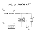
- Fig. 2 shows a conventional diversity receiving apparatus in which a gain synthesizing method is used to maximize a C/N ratio after diversity synthesis.
- one receiving system comprises an antenna 21 and a receiver 22 connected to the antenna 21, and the other receiving system comprises an antenna 23 and a receiver 24 connected to the antenna 23.
- An adder 25 adds a reception signal output from the receiver 22 to a reception signal output from the receiver 24 to synthesize them, and a phase shifter 26 is provided between the receiver 24 and the adder 25.
- a phase difference detector 27 detects the phase difference between the reception signal output from the receiver 22 and the reception signal output from the receiver 24 and thus the phase shifter 26 is controlled based on the detected results.
- the phase difference detector 27 controls the phase shifter 26 to remove the phase difference.
- the phase difference detector 27 controls the phase shifter 26 to remove the phase difference.
- two reception signals to be input into the adder 25 are controlled to have the same phases, and thus the signal synthesized by the adder 25 has the maximum C/N ratio (for example, see Non-Patent Document 1).
- the reception signal synthesized by the adder 25 is converted into a base-band signal by OFDM demodulating means (not shown).
- phase of the signal having a high C/N ratio is controlled so as to match to the phase of the signal having a low C/N ratio. Therefore, in an extreme case, the phase of the signal having a high C/N ratio is continuously varied for phase matching, and thus it is difficult to improve a C/N ratio of the synthesized signal and to synchronize signals.
- the present invention is made to solve the above problems, and it is an object of the present invention to prevent reduction in C/N ratio when phases of the signals to be input into adding means are matched to perform diversity synthesis and to easily synchronize signals during demodulation.
- a diversity receiving apparatus comprising a plurality of antennas, a plurality of receiving circuits connected to the plurality of antennas, respectively, adding means for adding reception signals output from the respective receiving circuits, and phase shifting means for making phases of the reception signals to be input into the adding means equal, wherein level comparing means for comparing the levels of the reception signals output from the respective receiving circuits is provided, phases of reception signals other than the maximum-level reception signal are controlled so as to match to the phase of the maximum-level reception signal, and then the phase-controlled signals are input into the adding means.
- the diversity receiving apparatus further comprises phase controlling means for controlling the amount of phase shift of the phase shifting means, the phase shifting means is provided in each receiving system between the antenna and the adding means, and the phase controlling means is controlled by the level comparing means so as to control only the amount of phase shift of the phase shifting means corresponding to the reception signals other than the maximum-level reception signal.
- Fig. 1 illustrates two receiving systems.
- a first receiving circuit 2 is connected to a first antenna 1.
- the first receiving circuit 2 comprises a first low-noise amplifier 2a for amplifying a reception signal, a first mixer 2b for converting frequency of the amplified signal, a first oscillator 2c for supplying a local oscillation signal to the first mixer 2b, a first PLL circuit 2d for controlling an oscillation frequency of the first oscillator 2c, a first intermediate frequency amplifier 2f for amplifying an intermediate frequency signal output from the first mixer 2b, and a first band-pass filter 2e interposed between the first mixer 2b and the first intermediate frequency amplifier 2f.
- a second receiving circuit 4 is connected to a second antenna 3.
- the second receiving circuit 4 comprises a second low-noise amplifier 4a for amplifying a reception signal, a second mixer 4b for frequency-converting the amplified signal, a second oscillator 4c for supplying a local oscillation signal to the second mixer 4b, a second PLL circuit 4d for controlling an oscillation frequency of the second oscillator 4c, a second intermediate frequency amplifier 4f for amplifying an intermediate frequency signal output from the second mixer 4b, and a second band-pass filter 4e provided between the second mixer 4b and the second intermediate frequency amplifier 4f.
- a reference oscillator 5 supplies a reference signal to the first PLL circuit 2d and the second PLL circuit 4d.
- the signal (the intermediate frequency signal) output from the first receiving circuit 2 is input into adding means 7 via first phase shifting means 6, and the signal output from the second receiving circuit 4 is input into the adding means 7 via second phase shifting means 8.
- the first and second phase shifting means 6 and 8 do not necessarily interpose between the receiving means 2 and 4 and the adding means 7, respectively.
- the first and second phase shifting means 6 and 8 may be provided in the receiving means 2 and 4, respectively, to vary the phase of a local oscillation signal.
- the first and second phase shifting means 2 and 4 may be provided at any position where the respective reception signals which are input into the adding means 7 to have the same phase.
- Phase controlling means 9 controls the amount of phase shift imparted by the first and second phase shifting means 6 and 8.
- level comparing means 10 is provided for comparing the levels of the signal output from the first receiving circuit 2 and the signal output from the second receiving circuit 4 and for controlling the phase controlling means based on the level difference.
- the level comparing means 10 comprises first detecting means 10a for detecting the level of the signal output from the first receiving circuit 2, second detecting means 10b for detecting the level of the signal output from the second receiving circuit 4, and comparing means 10c for comparing the two detected levels.
- a detection signal output from the first detecting means 10a is input to a non-inversion input terminal (+) of the comparing means 10c, and a detection signal output from the second detecting means 10b is input to an inversion input terminal (-) thereof. Therefore, the comparing means 10c outputs a voltage corresponding to the difference between levels detected by the detecting means 10a and 10b. In this way, the comparing means 10c controls the phase controlling means 9.
- the phase controlling means 9 controls two reception signals to be input into the adding means 7 to have the same phase based on the comparison results from the comparing means 10c, so that the added signal has the maximum level. That is, the phase controlling means 9 is controlled by the comparing means 10c such that phases of signals other than the maximum level signal among the signals to be input into the adding means 7 are controlled to have the same phase as the maximum level signal.
- Fig. 1 illustrates a case in which two signals are received. Therefore, example, when the level of the signal output from the first receiving circuit 2 is high and the level of the signal output from the second receiving circuit 4 is low, the signal output from the second receiving circuit 4 is a signal other than the maximum level signal.
- the phase controlling means 9 does not control the phase of the signal output from the first receiving circuit 2, but controls the second phase shifting means 8 such that the phase of the signal output from the second receiving circuit 4 is varied until the signal output from the adding means 7 reaches the maximum level. As such, when two signals to be input into the adding means 7 are controlled to have the same phase, the level of the added signal is maximized.
- the present invention is not limited thereto and may be formed of three receiving systems including antennas and receiving circuits.
- the levels of reception signals input into the respective receiving systems are compared with each other by the level comparing means 10, the phases of signals other than the maximum level signal are controlled so as to have the same phase as the phase of the maximum level signal, and the phase-controlled signals are input into the adding means 7.
- the level comparing means 10 may be formed of a digital circuit as well as an analog circuit to digitally control the phase controlling means 9. Also, it is preferable that the comparing means 10c have a hysteresis characteristic in order to stabilize the operation of the phase controlling means 9.
- a diversity receiving apparatus comprises a plurality of antennas, a plurality of receiving circuits connected to the plurality of antennas, respectively, adding means for adding reception signals output from the respective receiving circuits, and phase shifting means for making phases of the reception signals to be input into the adding means equal, wherein level comparing means for comparing the levels of the reception signals output from the respective receiving circuits is provided, the phases of signals other than the maximum level signal are controlled so as to have the same phase as the phase of the maximum level signal, and the phase-controlled signals are input into the adding means.
- the phase of the maximum level signal is not controlled, the phase thereof is not varied, and a C/N ratio thereof is not reduced.
- the diversity receiving apparatus further comprises phase controlling means for controlling the amount of phase shift of the phase shifting means, the phase shifting means is provided in every receiving system between the antenna and the adding means, and the phase controlling means is controlled by the level comparing means so as to controls only the amount of phase shift of the phase shifting means corresponding to the reception signals other than the maximum level signal. Therefore, even though a signal input into any receiving system has the maximum level, the phases of the signals other than the maximum level signal can be controlled.
Landscapes
- Engineering & Computer Science (AREA)
- Computer Networks & Wireless Communication (AREA)
- Signal Processing (AREA)
- Radio Transmission System (AREA)
Abstract
There is provided a diversity receiving apparatus
capable of preventing a reduction in C/N ratio when
phases of signals to be input into adding means are
matched for diversity synthesis and of easily taking
synchronization during demodulation. The diversity
receiving apparatus comprises a plurality of antennas 1
and 3, a plurality of receiving circuits 2 and 4
connected to the plurality of antennas 1 and 3,
respectively, adding means 7 for adding reception signals
output from the respective receiving circuits 2 and 4,
and phase shifting means 6 and 8 for making phases of the
reception signals to be input into the adding means 7
equal, wherein level comparing means 10 for comparing the
levels of the reception signals output from the
respective receiving circuits 2 and 4 is provided, phases
of reception signals other than a maximum-level reception
signal are controlled so as to have the same phase as the
phase of the maximum-level reception signal, and the
phase-controlled signals are input into the adding means.
Description
- The present invention relates to a diversity receiving apparatus suitable for a vehicle-mounted receiver for terrestrial digital TV broadcasting that is driven using an OFDM (Orthogonal Frequency Division Multiplex) method.
- Fig. 2 shows a conventional diversity receiving apparatus in which a gain synthesizing method is used to maximize a C/N ratio after diversity synthesis. In Fig. 2, one receiving system comprises an
antenna 21 and areceiver 22 connected to theantenna 21, and the other receiving system comprises anantenna 23 and areceiver 24 connected to theantenna 23. - An
adder 25 adds a reception signal output from thereceiver 22 to a reception signal output from thereceiver 24 to synthesize them, and aphase shifter 26 is provided between thereceiver 24 and theadder 25. In addition, aphase difference detector 27 detects the phase difference between the reception signal output from thereceiver 22 and the reception signal output from thereceiver 24 and thus thephase shifter 26 is controlled based on the detected results. - According to this configuration, when a phase difference exists between two reception signals, the
phase difference detector 27 controls thephase shifter 26 to remove the phase difference. As a result, two reception signals to be input into theadder 25 are controlled to have the same phases, and thus the signal synthesized by theadder 25 has the maximum C/N ratio (for example, see Non-Patent Document 1). - 'Modulation and Demodulation in Digital Wireless Communication' written by Yoichi Saito and published by the Institute of Electronics, Information and Communication Engineers of Japan (IEICE) on February 10, 1996, pp. 189 to 191 and Fig. 5.19
- The reception signal synthesized by the
adder 25 is converted into a base-band signal by OFDM demodulating means (not shown). - According to the aforementioned method, for example, when the
antenna 21 receives a signal having a low C/N ratio that mainly includes noise components and theantenna 22 receives a signal having a high C/N ratio that mainly includes signal components, phase of the signal having a high C/N ratio is controlled so as to match to the phase of the signal having a low C/N ratio. Therefore, in an extreme case, the phase of the signal having a high C/N ratio is continuously varied for phase matching, and thus it is difficult to improve a C/N ratio of the synthesized signal and to synchronize signals. - The present invention is made to solve the above problems, and it is an object of the present invention to prevent reduction in C/N ratio when phases of the signals to be input into adding means are matched to perform diversity synthesis and to easily synchronize signals during demodulation.
- In order to achieve the above object, there is provided a diversity receiving apparatus comprising a plurality of antennas, a plurality of receiving circuits connected to the plurality of antennas, respectively, adding means for adding reception signals output from the respective receiving circuits, and phase shifting means for making phases of the reception signals to be input into the adding means equal, wherein level comparing means for comparing the levels of the reception signals output from the respective receiving circuits is provided, phases of reception signals other than the maximum-level reception signal are controlled so as to match to the phase of the maximum-level reception signal, and then the phase-controlled signals are input into the adding means.
- Furthermore, according to the present invention, the diversity receiving apparatus further comprises phase controlling means for controlling the amount of phase shift of the phase shifting means, the phase shifting means is provided in each receiving system between the antenna and the adding means, and the phase controlling means is controlled by the level comparing means so as to control only the amount of phase shift of the phase shifting means corresponding to the reception signals other than the maximum-level reception signal.
-
- Fig. 1 is a circuit diagram illustrating the structure of a diversity receiving apparatus according to the present invention; and
- Fig. 2 is a circuit diagram illustrating the structure of a conventional diversity receiving apparatus.
-
- A diversity receiving apparatus according to the present invention will now be described with reference to Fig. 1. Fig. 1 illustrates two receiving systems.
- A
first receiving circuit 2 is connected to afirst antenna 1. Thefirst receiving circuit 2 comprises a first low-noise amplifier 2a for amplifying a reception signal, afirst mixer 2b for converting frequency of the amplified signal, afirst oscillator 2c for supplying a local oscillation signal to thefirst mixer 2b, afirst PLL circuit 2d for controlling an oscillation frequency of thefirst oscillator 2c, a firstintermediate frequency amplifier 2f for amplifying an intermediate frequency signal output from thefirst mixer 2b, and a first band-pass filter 2e interposed between thefirst mixer 2b and the firstintermediate frequency amplifier 2f. - A second receiving circuit 4 is connected to a second antenna 3. The second receiving circuit 4 comprises a second low-
noise amplifier 4a for amplifying a reception signal, asecond mixer 4b for frequency-converting the amplified signal, a second oscillator 4c for supplying a local oscillation signal to thesecond mixer 4b, asecond PLL circuit 4d for controlling an oscillation frequency of the second oscillator 4c, a second intermediate frequency amplifier 4f for amplifying an intermediate frequency signal output from thesecond mixer 4b, and a second band-pass filter 4e provided between thesecond mixer 4b and the second intermediate frequency amplifier 4f. - A reference oscillator 5 supplies a reference signal to the
first PLL circuit 2d and thesecond PLL circuit 4d. - The signal (the intermediate frequency signal) output from the
first receiving circuit 2 is input into addingmeans 7 via first phase shifting means 6, and the signal output from the second receiving circuit 4 is input into the addingmeans 7 via second phase shifting means 8. Note that the first and second phase shifting means 6 and 8 do not necessarily interpose between thereceiving means 2 and 4 and the addingmeans 7, respectively. Alternatively, for example, the first and second phase shifting means 6 and 8 may be provided in thereceiving means 2 and 4, respectively, to vary the phase of a local oscillation signal. In short, the first and second phase shifting means 2 and 4 may be provided at any position where the respective reception signals which are input into the addingmeans 7 to have the same phase. Phase controlling means 9 controls the amount of phase shift imparted by the first and second phase shifting means 6 and 8. - Furthermore, level comparing means 10 is provided for comparing the levels of the signal output from the
first receiving circuit 2 and the signal output from the second receiving circuit 4 and for controlling the phase controlling means based on the level difference. - The level comparing means 10 comprises first detecting means 10a for detecting the level of the signal output from the
first receiving circuit 2, second detecting means 10b for detecting the level of the signal output from the second receiving circuit 4, and comparingmeans 10c for comparing the two detected levels. A detection signal output from the first detecting means 10a is input to a non-inversion input terminal (+) of the comparing means 10c, and a detection signal output from the second detecting means 10b is input to an inversion input terminal (-) thereof. Therefore, the comparing means 10c outputs a voltage corresponding to the difference between levels detected by the detecting means 10a and 10b. In this way, the comparing means 10c controls thephase controlling means 9. - The phase controlling means 9 controls two reception signals to be input into the adding
means 7 to have the same phase based on the comparison results from thecomparing means 10c, so that the added signal has the maximum level. That is, the phase controllingmeans 9 is controlled by thecomparing means 10c such that phases of signals other than the maximum level signal among the signals to be input into the addingmeans 7 are controlled to have the same phase as the maximum level signal. Fig. 1 illustrates a case in which two signals are received. Therefore, example, when the level of the signal output from thefirst receiving circuit 2 is high and the level of the signal output from the second receiving circuit 4 is low, the signal output from the second receiving circuit 4 is a signal other than the maximum level signal. - Thus, the phase controlling means 9 does not control the phase of the signal output from the
first receiving circuit 2, but controls the second phase shifting means 8 such that the phase of the signal output from the second receiving circuit 4 is varied until the signal output from the addingmeans 7 reaches the maximum level. As such, when two signals to be input into the addingmeans 7 are controlled to have the same phase, the level of the added signal is maximized. - During this process, since the phase of the maximum level signal output from the
first receiving circuit 2 is not controlled, the phase of the signal is not varied, and thus a C/N ratio thereof is not reduced. Therefore, synchronization can be easily achieved when demodulated by using OFDM demodulating means (although not shown, which is connected to the latter part of the adding means 7). - As a specific example, two receiving systems including antennas and receiving circuits are illustrated in Fig. 1. However, the present invention is not limited thereto and may be formed of three receiving systems including antennas and receiving circuits. In short, preferably, the levels of reception signals input into the respective receiving systems are compared with each other by the level comparing means 10, the phases of signals other than the maximum level signal are controlled so as to have the same phase as the phase of the maximum level signal, and the phase-controlled signals are input into the adding
means 7. - Furthermore, the level comparing means 10 may be formed of a digital circuit as well as an analog circuit to digitally control the
phase controlling means 9. Also, it is preferable that the comparing means 10c have a hysteresis characteristic in order to stabilize the operation of thephase controlling means 9. - As described above, a diversity receiving apparatus according to the present invention comprises a plurality of antennas, a plurality of receiving circuits connected to the plurality of antennas, respectively, adding means for adding reception signals output from the respective receiving circuits, and phase shifting means for making phases of the reception signals to be input into the adding means equal, wherein level comparing means for comparing the levels of the reception signals output from the respective receiving circuits is provided, the phases of signals other than the maximum level signal are controlled so as to have the same phase as the phase of the maximum level signal, and the phase-controlled signals are input into the adding means. Thus, since the phase of the maximum level signal is not controlled, the phase thereof is not varied, and a C/N ratio thereof is not reduced.
- Furthermore, according to the present invention, the diversity receiving apparatus further comprises phase controlling means for controlling the amount of phase shift of the phase shifting means, the phase shifting means is provided in every receiving system between the antenna and the adding means, and the phase controlling means is controlled by the level comparing means so as to controls only the amount of phase shift of the phase shifting means corresponding to the reception signals other than the maximum level signal. Therefore, even though a signal input into any receiving system has the maximum level, the phases of the signals other than the maximum level signal can be controlled.
Claims (2)
- A diversity receiving apparatus comprising a plurality of antennas, a plurality of receiving circuits connected to the plurality of antennas, respectively, adding means for adding reception signals output from the respective receiving circuits, and phase shifting means for making phases of the reception signals to be input into the adding means equal,
wherein level comparing means for comparing the levels of the reception signals output from the respective receiving circuits is provided, and
wherein phases of reception signals other than a maximum-level reception signal are controlled so as to have the same phase as the phase of the maximum-level reception signal, and the phase-controlled signals are input into the adding means. - The diversity receiving apparatus according to Claim 1, further comprising phase controlling means for controlling the amount of phase shift of the phase shifting means,
wherein the phase shifting means is provided in each receiving system from the antenna to the adding means, and
wherein the phase controlling means is controlled by the level comparing means so as to control only the amount of phase shift of the phase shifting means corresponding to the reception signals other than the maximum-level reception signal.
Applications Claiming Priority (2)
| Application Number | Priority Date | Filing Date | Title |
|---|---|---|---|
| JP2003105792A JP2004312562A (en) | 2003-04-09 | 2003-04-09 | Diversity receiving device |
| JP2003105792 | 2003-04-09 |
Publications (1)
| Publication Number | Publication Date |
|---|---|
| EP1467502A2 true EP1467502A2 (en) | 2004-10-13 |
Family
ID=32866755
Family Applications (1)
| Application Number | Title | Priority Date | Filing Date |
|---|---|---|---|
| EP04006247A Withdrawn EP1467502A2 (en) | 2003-04-09 | 2004-03-16 | Diversity receiving apparatus capable of preventing reduction of C/N ratio |
Country Status (3)
| Country | Link |
|---|---|
| US (1) | US6961394B2 (en) |
| EP (1) | EP1467502A2 (en) |
| JP (1) | JP2004312562A (en) |
Cited By (1)
| Publication number | Priority date | Publication date | Assignee | Title |
|---|---|---|---|---|
| FR2905814A1 (en) * | 2006-09-13 | 2008-03-14 | France Telecom | METHOD FOR RECEIVING MODULAR AMRF SIGNALS AND RECEIVING DEVICE USING THE SAME. |
Families Citing this family (2)
| Publication number | Priority date | Publication date | Assignee | Title |
|---|---|---|---|---|
| JP7275651B2 (en) * | 2019-02-28 | 2023-05-18 | 沖電気工業株式会社 | radio equipment |
| US10680694B1 (en) * | 2020-01-29 | 2020-06-09 | The Florida International University Board Of Trustees | Cross-mixing beamformer |
Family Cites Families (5)
| Publication number | Priority date | Publication date | Assignee | Title |
|---|---|---|---|---|
| JPS5683146A (en) * | 1979-10-31 | 1981-07-07 | Nec Corp | Synthesizing system of pass band optimum ratio in diversity communication |
| US4373207A (en) * | 1980-12-17 | 1983-02-08 | Bell Telephone Laboratories, Incorporated | Space diversity signal combiner |
| CA2029876C (en) * | 1989-03-28 | 1999-08-24 | Shigeki Saito | Diversity receiver |
| JP2713128B2 (en) * | 1993-12-28 | 1998-02-16 | 日本電気株式会社 | Diversity reception signal synthesis circuit |
| JP2003318857A (en) | 2002-04-25 | 2003-11-07 | Mitsubishi Electric Corp | Digital broadcast receiver |
-
2003
- 2003-04-09 JP JP2003105792A patent/JP2004312562A/en not_active Withdrawn
-
2004
- 2004-03-16 EP EP04006247A patent/EP1467502A2/en not_active Withdrawn
- 2004-03-29 US US10/811,648 patent/US6961394B2/en not_active Expired - Lifetime
Cited By (2)
| Publication number | Priority date | Publication date | Assignee | Title |
|---|---|---|---|---|
| FR2905814A1 (en) * | 2006-09-13 | 2008-03-14 | France Telecom | METHOD FOR RECEIVING MODULAR AMRF SIGNALS AND RECEIVING DEVICE USING THE SAME. |
| WO2008031963A1 (en) * | 2006-09-13 | 2008-03-20 | France Telecom | Method of receiving amrf-modulated signals and reception device implementing this method |
Also Published As
| Publication number | Publication date |
|---|---|
| JP2004312562A (en) | 2004-11-04 |
| US20040203545A1 (en) | 2004-10-14 |
| US6961394B2 (en) | 2005-11-01 |
Similar Documents
| Publication | Publication Date | Title |
|---|---|---|
| US6757029B2 (en) | Television receiving apparatus | |
| EP0813312A2 (en) | Multiband mobile unit communication apparatus | |
| EP1290469B1 (en) | Integrated gps/dab receiver | |
| EP1318641A2 (en) | Carrier recovery with antenna diversity | |
| US7454180B2 (en) | Vehicle-mounted receiving apparatus for reducing distortion, improving reception sensitivity, and saving power | |
| EP1274181A1 (en) | Multiantennae receiver for improving the carrier-to-noise ratio by adapting the phases of the antenna signals | |
| EP1463214A2 (en) | Diversity reception device outputting maximized C/N ratio of synthesized signal | |
| US20020140872A1 (en) | Dual digital television tuner | |
| US7376406B2 (en) | Diversity reception apparatus | |
| US6961394B2 (en) | Diversity receiving apparatus capable of preventing reduction of C/N ratio | |
| EP1083673A1 (en) | Radio device and transmitting/receiving method | |
| US6633345B2 (en) | Receiver selectively receiving, demodulating and outputting a tv broadcast signal and an FM radio broadcast signal | |
| US20100045874A1 (en) | Intermediate frequency processing device for processing both analogue and digital television intermediate frequency signals | |
| EP1686704A2 (en) | Vehicle-mounted receiving apparatus | |
| US20070146550A1 (en) | Receiving circuit, receiving apparatus, and receiving method | |
| JP2003179531A (en) | Ofdm signal receiver | |
| US20070071148A1 (en) | Diversity reception circuit | |
| EP0757483A2 (en) | Digital I-Q converter circuit | |
| JP3100994B2 (en) | Receiving level display circuit in satellite broadcasting receiver | |
| JP3342854B2 (en) | In-phase synthesis / phase difference detection circuit | |
| JP2002135668A (en) | Digital broadcast receiver | |
| JP2001024721A (en) | Shared receiver | |
| JPH0564101A (en) | Receiver including at least two types of demodulation circuits sharing a tuner device | |
| JPH07107024A (en) | Diversity circuit | |
| JP2007281653A (en) | Semiconductor integrated circuit, TV broadcast receiving apparatus and TV broadcast receiving method |
Legal Events
| Date | Code | Title | Description |
|---|---|---|---|
| PUAI | Public reference made under article 153(3) epc to a published international application that has entered the european phase |
Free format text: ORIGINAL CODE: 0009012 |
|
| AK | Designated contracting states |
Kind code of ref document: A2 Designated state(s): AT BE BG CH CY CZ DE DK EE ES FI FR GB GR HU IE IT LI LU MC NL PL PT RO SE SI SK TR |
|
| AX | Request for extension of the european patent |
Extension state: AL LT LV MK |
|
| STAA | Information on the status of an ep patent application or granted ep patent |
Free format text: STATUS: THE APPLICATION HAS BEEN WITHDRAWN |
|
| 18W | Application withdrawn |
Effective date: 20090821 |