EP1467424A1 - Method of producing fuel cell-use separator and device for producing it - Google Patents
Method of producing fuel cell-use separator and device for producing it Download PDFInfo
- Publication number
- EP1467424A1 EP1467424A1 EP02790738A EP02790738A EP1467424A1 EP 1467424 A1 EP1467424 A1 EP 1467424A1 EP 02790738 A EP02790738 A EP 02790738A EP 02790738 A EP02790738 A EP 02790738A EP 1467424 A1 EP1467424 A1 EP 1467424A1
- Authority
- EP
- European Patent Office
- Prior art keywords
- etching
- metal material
- separator
- tank
- passivation treatment
- Prior art date
- Legal status (The legal status is an assumption and is not a legal conclusion. Google has not performed a legal analysis and makes no representation as to the accuracy of the status listed.)
- Granted
Links
Images


Classifications
-
- H—ELECTRICITY
- H01—ELECTRIC ELEMENTS
- H01M—PROCESSES OR MEANS, e.g. BATTERIES, FOR THE DIRECT CONVERSION OF CHEMICAL ENERGY INTO ELECTRICAL ENERGY
- H01M8/00—Fuel cells; Manufacture thereof
- H01M8/02—Details
- H01M8/0202—Collectors; Separators, e.g. bipolar separators; Interconnectors
- H01M8/0204—Non-porous and characterised by the material
- H01M8/0206—Metals or alloys
-
- H—ELECTRICITY
- H01—ELECTRIC ELEMENTS
- H01M—PROCESSES OR MEANS, e.g. BATTERIES, FOR THE DIRECT CONVERSION OF CHEMICAL ENERGY INTO ELECTRICAL ENERGY
- H01M8/00—Fuel cells; Manufacture thereof
- H01M8/02—Details
-
- H—ELECTRICITY
- H01—ELECTRIC ELEMENTS
- H01M—PROCESSES OR MEANS, e.g. BATTERIES, FOR THE DIRECT CONVERSION OF CHEMICAL ENERGY INTO ELECTRICAL ENERGY
- H01M8/00—Fuel cells; Manufacture thereof
- H01M8/02—Details
- H01M8/0202—Collectors; Separators, e.g. bipolar separators; Interconnectors
- H01M8/0204—Non-porous and characterised by the material
- H01M8/0223—Composites
- H01M8/0228—Composites in the form of layered or coated products
-
- Y—GENERAL TAGGING OF NEW TECHNOLOGICAL DEVELOPMENTS; GENERAL TAGGING OF CROSS-SECTIONAL TECHNOLOGIES SPANNING OVER SEVERAL SECTIONS OF THE IPC; TECHNICAL SUBJECTS COVERED BY FORMER USPC CROSS-REFERENCE ART COLLECTIONS [XRACs] AND DIGESTS
- Y02—TECHNOLOGIES OR APPLICATIONS FOR MITIGATION OR ADAPTATION AGAINST CLIMATE CHANGE
- Y02E—REDUCTION OF GREENHOUSE GAS [GHG] EMISSIONS, RELATED TO ENERGY GENERATION, TRANSMISSION OR DISTRIBUTION
- Y02E60/00—Enabling technologies; Technologies with a potential or indirect contribution to GHG emissions mitigation
- Y02E60/30—Hydrogen technology
- Y02E60/50—Fuel cells
-
- Y—GENERAL TAGGING OF NEW TECHNOLOGICAL DEVELOPMENTS; GENERAL TAGGING OF CROSS-SECTIONAL TECHNOLOGIES SPANNING OVER SEVERAL SECTIONS OF THE IPC; TECHNICAL SUBJECTS COVERED BY FORMER USPC CROSS-REFERENCE ART COLLECTIONS [XRACs] AND DIGESTS
- Y02—TECHNOLOGIES OR APPLICATIONS FOR MITIGATION OR ADAPTATION AGAINST CLIMATE CHANGE
- Y02P—CLIMATE CHANGE MITIGATION TECHNOLOGIES IN THE PRODUCTION OR PROCESSING OF GOODS
- Y02P70/00—Climate change mitigation technologies in the production process for final industrial or consumer products
- Y02P70/50—Manufacturing or production processes characterised by the final manufactured product
-
- Y—GENERAL TAGGING OF NEW TECHNOLOGICAL DEVELOPMENTS; GENERAL TAGGING OF CROSS-SECTIONAL TECHNOLOGIES SPANNING OVER SEVERAL SECTIONS OF THE IPC; TECHNICAL SUBJECTS COVERED BY FORMER USPC CROSS-REFERENCE ART COLLECTIONS [XRACs] AND DIGESTS
- Y10—TECHNICAL SUBJECTS COVERED BY FORMER USPC
- Y10T—TECHNICAL SUBJECTS COVERED BY FORMER US CLASSIFICATION
- Y10T29/00—Metal working
- Y10T29/49—Method of mechanical manufacture
- Y10T29/49002—Electrical device making
- Y10T29/49117—Conductor or circuit manufacturing
Definitions
- This invention relates to a fuel cell separator manufacturing method and manufacturing apparatus suitable for achieving productivity improvement, cost reduction, quality improvement and quality stabilization of a metal separator.
- solid high polymer electrolyte fuel cell units because they are of a structure such that the desired output is obtained by stacking together multiple fuel cells, for the separators that divide these fuel cells, metal materials, which compared to polymer materials are stronger with respect to pressure applied at the time of stacking and are advantageous to size reduction after stacking, are seen as leading.
- Known fuel cells employing metal separators of this kind include for example 1 ⁇ JP-A-8-180883, “Solid High Polymer Electrolyte Fuel Cell” (hereinafter, Related Art 1 ⁇ ), 2 ⁇ JP-A-2000-164228, “Solid High Polymer Electrolyte Fuel Cell Separator and Manufacturing Method Thereof” (hereinafter, Related Art 2 ⁇ ).
- Electrodes films are disposed on both sides of a solid high polymer electrolyte film, these electrode films are sandwiched with for example stainless steel separators, and the edge parts of the separators are sealed with seals.
- a single cell of a fuel cell wherein an anode electrode and a cathode electrode are disposed on either side of a solid high polymer film, and the anode electrode and the cathode electrode are sandwiched by separators with for example stainless steel as their base material.
- a metal material 400 to constitute the material of a separator is rolled before being press-formed to a predetermined shape.
- an abnormal layer 401 is formed at the surface layer of the metal material 400.
- the above-mentioned abnormal layer 401 is removed by etching.
- a first passivation treatment is carried out and a first passivation film 402 is formed.
- particulate conductors 403... (... denotes a plurality. The same applies hereinafter.) consisting of the above-mentioned intermetallic compounds naturally included in the metal material 400 are good electrical conductors, with the object of reducing the electrical contact resistance between the separator and an adjacent separator or electrode when the metal material 400 is made a separator and stacked in a fuel cell, exposing of the conductors 403... is carried out. To perform this exposing, etching is carried out.
- ST101 A metal material press-formed after rolling is degreased.
- the process liquid is an aqueous surfactant solution, the treatment temperature is 30°C, and the treatment time is 1 minute.
- the abnormal layer formed at the time of rolling is removed by etching.
- the process liquid is a solution of aqua regia and a surfactant, the treatment temperature is 98°C, and the treatment time is 60 minutes.
- a first passivation treatment is carried out.
- the process liquid is 50% nitric acid, the treatment temperature is 50°C and the treatment time is 30 minutes.
- the metal material is washed.
- the treatment time is 1 minute.
- the process liquid is a solution of 20% nitric acid and 8% hydrofluoric acid, the treatment temperature is 30°C and the treatment time is 10 minutes.
- the process liquid is 50% nitric acid, the treatment temperature is 50°C and the treatment time is 30 minutes.
- the metal material is dried.
- the treatment time is 1 minute.
- the total process time is 137 minutes.
- the contact resistance of the separator is made small.
- the required time from the degreasing of ST101 to the drying of ST111 is 137 minutes in total, and because the number of process steps is large the number of different process liquids and the number of process tanks for holding the process liquids are large and much labor is taken in the temperature management of the process liquids, and consequently, to achieve productivity improvement and cost reduction of metal separators, a reduction in the above-mentioned number of process steps has been needed.
- the quality of the separators can be increased and the quality of the separators can be stabilized, and when the intended processing has not been carried out on a metal material the waste of continuing processing with subsequent steps can also be eliminated.
- Fig. 23 shows a process tank 411 filled with a process liquid 412 and a metal material 414 (a material to eventually become a separator) held in a frame-shaped member 413 immersed in this process liquid 412.
- 415 is a wire suspending the frame-shaped member 413.
- the separator accounts for most of the cost. This is because the separator requires a structure finely formed with flow passages for fuel gas and oxidant gas and cooling water, and surface treatment to prevent corrosion by electrolytes. Accordingly, if the productivity of the separators is raised and their cost reduced, the cost of fuel cells is greatly reduced and a contribution is made to the spread of fuel cell vehicles.
- Fig. 23 for example when the metal material 414 is treated with the process liquid 412 of the above-mentioned process tank 411, (1) to quicken the treatment of the metal material 414 and also to effect it uniformly, it is effective to agitate the process liquid 412 with an agitating device, but when there are multiple process tanks 411, an agitating device must be provided for each of them, leading to increased cost, and (2) if the carrying of the metal material 414 to the process tanks 411 and the holding of the metal material 414 for the immersion of the carried metal material 414 in the process liquid 412 are not coordinated well, the flow of the production process cannot be made smooth, and the production time increases, and (3) if the number of metal materials processed at once is low, the number of units produced per unit time is low, and if this can be improved, productivity improvement and cost reduction of separators can be achieved.
- the invention provides a fuel cell separator manufacturing method comprising an abnormal layer removing step of removing an abnormal layer arising at the surface layer of a metal material to be used as a separator when it is rolled; a conductor exposing step of causing portions of conductors included in a surface layer part of the metal material itself to project; and a passivation treatment step of carrying out a passivation treatment on the surface layer part of the metal material itself.
- the removing of the abnormal layer with the abnormal layer removing step and the removing of the surface layer part of the separator with the conductor exposing step are possible in the same process, chemically or electro-chemically, and the number of steps can be cut and increased productivity and reduced cost of separators can be achieved.
- the method of the invention comprises: a step of rolling a metal material with rolling means; a step of forming the rolled material to a predetermined shape with pressing means; the abnormal layer removing step and the conductor exposing step carried out by etching; and the passivation treatment step, and the abnormal layer removal step and the conductor exposing step are carried out in a single etching.
- the above-mentioned etching process is carried out with the temperature and composition of the etching liquid selected in correspondence with the state of the abnormal layer.
- constituents with a stronger abnormal layer removing action as the constituents of the etching liquid and raising the temperature of the etching liquid when the abnormal layer is formed thick to the extent that conductors cannot be confirmed by visual observation
- constituents with a weaker abnormal layer removing action as the constituents of the etching liquid and making the temperature of the etching liquid low when the abnormal layer is formed thin to the extent that conductors can be confirmed by visual observation
- the etching is carried out with the agitation method changed in correspondence with the state of the abnormal layer.
- the etching is carried out with the concentration of the etching liquid changed in correspondence with the state of the abnormal layer.
- the etching is carried out in a liquid tank selected from among a plurality of liquid tanks holding etching liquids of different compositions.
- the removal of the abnormal layer is promoted by a granular material being mixed with the etching liquid and the etching liquid being agitated.
- the method of the invention comprises: the abnormal layer removing step; a first checking step of checking the weight of the metal material after the abnormal layer is removed; a first passivation treatment step of carrying out a passivation treatment for corrosion resistance on the metal material; the conductor exposing step carried out by etching; a second checking step of checking the weight of the metal material after this step; and a second passivation treatment step of carrying out a passivation treatment again after this, and confirmation of the respective weights is carried out in the first checking step and the second checking step.
- the weight of abnormal layer removed can be confirmed, and if the weight of the metal material measured in the second checking step and the weight measured in the first checking step are compared, an exposure weight constituting a weight of metal material removed to expose the conductors can be confirmed, and an improvement in the quality of the metal material and stabilization of the quality can be achieved.
- the first checking step and the second checking step are carried out after the metal material is washed and dried.
- first checking step and the second checking step being carried out after the metal material is washed and dried, adhered matter adhered to the metal material surface can be removed, and the measurement accuracy of the weight of the metal material in the first checking step and the second checking step can be raised.
- the subsequent steps are not carried out.
- the determination of whether or not the weight obtained in the first checking step and the second checking step is within a predetermined range is carried out by automatic determining means.
- a separator is manufactured from: a step of press-forming the metal material to a predetermined shape; a step of holding a plurality of such formed metal materials on cylindrical holding jig; a step of immersing the held metal materials in a process liquid contained in a process tank and agitating the process liquid with the metal material by driving the cylindrical holding jig with driving means; the abnormal layer removing step; the conductor exposing step; the passivation treatment step; and a step of removing the metal materials from the process tank and drying them.
- the treatment of the metal materials can be quickened and the treatment can be carried out uniformly. Therefore, separators of superior quality can be manufactured efficiently.
- the separator production time can be shortened.
- multiple metal materials held on the cylindrical holding jig can be processed at once, and the number of units produced can be increased.
- the metal materials are held by being fitted in frame members provided on an outer face of the cylindrical holding jig.
- metal materials By the metal materials being held by being fitted in frame members, larger areas of the surfaces of the metal materials can be processed, and the metal materials can be treated effectively.
- it is made up of a step of rolling the metal material with rolling means; a step of forming the rolled material to a predetermined shape with pressing means; the abnormal layer removing step; the conductor exposing step; and the passivation treatment step, and the abnormal layer removing step and the conductor exposing step are carried out by electrolytic etching and this electrolytic etching step and the passivation treatment step are carried out consecutively using electrical potential control.
- the potential control when the metal material is made an anode and an electrode facing this anode is made a cathode, makes the potential difference between the anode and the cathode large in the electrolytic etching and makes the potential difference between the anode and the cathode small in the passivation treatment.
- the current density is kept constant.
- a second aspect of the invention provides a fuel cell separator manufacturing apparatus for manufacturing a separator by press-forming a rolled metal material to a predetermined shape and using etching to remove an abnormal layer arising in the metal material in the rolling and carry out exposing to cause portions of conductors included in a surface layer part of the metal material itself to project and carrying out a passivation treatment on the surface layer part of the metal material itself, the manufacturing apparatus comprising: a degreasing tank for degreasing the rolled metal material; an etching tank for carrying out the etching; a passivation treatment tank for carrying out the passivation treatment; cleaning tanks for removing respective process liquids from the metal material after the degreasing, after the etching and after the passivation treatment; a carrying apparatus for carrying the metal material to these tanks; a driving device for driving the metal material to agitate the process liquids in the tanks with the carried metal material itself; and a control unit for controlling the carrying apparatus and the driving device.
- a separator can be manufactured with a simpler construction, and the cost of the separator manufacturing apparatus can be reduced.
- the manufacturing apparatus comprises an abnormal layer removal tank for removing the abnormal layer, a passivation treatment tank for carrying out the passivation treatment, a conductor exposing tank for carrying out the exposing of conductors, weight measuring means for measuring the weight of the metal material after the abnormal layer removal and after the conductor exposure, and automatic determining means for determining on the basis of weight information from this weight measuring means whether or not the weight is in a predetermined range.
- the automatic determining means determines whether the weight of the metal material measured by the weight measuring means is not within a predetermined range. If it is determined by the automatic determining means that the weight of the metal material measured by the weight measuring means is not within a predetermined range, that metal material can be removed from the production process, and it is possible to stably manufacture separators of good quality only.
- the manufacturing apparatus comprises an etching tank for carrying out etching, a passivation treatment tank for carrying out passivation treatment, a cylindrical holding jig provided with frame members on an outer face thereof to hold a plurality of metal materials to be processed in the etching tank and the passivation treatment tank, driving means for driving the cylindrical holding jig to agitate process liquids of the etching tank and the passivation treatment tank with the metal materials held in this cylindrical holding jig, and carrying means for carrying the cylindrical holding jig to the etching tank and the passivation treatment tank.
- the cylindrical holding jig holding the metal materials can be used both as a metal material carrying tool and as a process liquid agitating tool, and compared to a case wherein these functions are performed by separate devices the number of parts can be reduced and the cost of the separator manufacturing apparatus can be reduced. And, because multiple metal materials can be held, carried, and agitated at once, the productivity of separators can be raised and the cost of separators can be lowered.
- the manufacturing apparatus comprises a process tank filled with a process liquid and having an electrode provided in the process liquid to electrolytically etch the metal material, electricity supply means for supplying electricity between a metal material immersed in the process liquid in this process tank and the electrode, current density detecting means for detecting the current density during the supply of electricity with this electricity supply means, potential control means for controlling the potential difference between the metal material and the electrode in correspondence with the current density detected by this current density detecting means, and a timer for sending a time signal to the potential control means to effect electricity supply for a predetermined time.
- separators can be manufactured with a simple construction, and the cost of the separator manufacturing apparatus can be reduced.
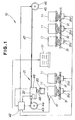
- a separator manufacturing apparatus 10 is made up of process tanks 11 holding process liquids for carrying out treatments which will be further discussed later, a dryer 17 for carrying out drying, a carrying apparatus 21 for carrying a separator workpiece 20 to the positions of the process tanks 11... and the dryer 17, a driving device 22 for driving an electric motor to raise and lower a separator workpiece 20 being moved by this carrying apparatus 21, lifters 31... for raising and lowering the process tanks 11... to immerse the separator workpiece 20 in the process liquids, liquid temperature adjusting devices 41... (although each of the process tanks 11...
- liquid temperature control devices 41 in the figure one is only drawn on one process tank 11
- control unit 42 for controlling the dryer 17, the carrying apparatus 21, the driving device 22, the lifters 31... and the liquid temperature control devices 41.
- 31d are lifter drivers for driving the lifters 31....
- the process tanks 11 are lined up in correspondence with steps shown in Fig. 4 and Fig. 5 (except for weighing steps and drying steps) which will be described later, and for example the leftmost process tank 11 in the figure is a process tank for a degreasing step constituting a first step in the production process.
- the separator workpiece 20 is eventually made into a separator by the separator manufacturing apparatus 10, and is made by rolling a metal material, for example stainless steel (particularly austenite stainless steel) into a thin sheet and then press-forming channels and holes in it for passing fuel gas, oxidant gas and cooling water in a fuel cell.
- a metal material for example stainless steel (particularly austenite stainless steel) into a thin sheet and then press-forming channels and holes in it for passing fuel gas, oxidant gas and cooling water in a fuel cell.
- the dryer 17 is a device operated and stopped by an ON/OFF signal from the control unit 42, and dries the separator workpiece 20 for example by fanning or by radiating heat at the separator workpiece 20.
- the carrying apparatus 21 is disposed above the process tanks 11... and the dryer 17 and is made up of a first drum 44 driven by a first electric motor 43, a second drum 46 driven by a second electric motor 45, a cable 47 running between the first drum 44 and the second drum 46, a separator carrying part 48 attached to this cable 47, and a weight sensor 49 serving as weighing means for measuring the weight of the separator workpiece 20.
- the first electric motor 43 and the second electric motor 45 are rotated synchronously by the control unit 42 to rotate the first drum 44 and the second drum 46 and move the separator carrying part 48, from which the separator workpiece 20 is suspended.
- a state is shown wherein with respect to a separator workpiece 20 for example a lifter 31 provided below a process tank 11 is driven to raise the process tank 11 and immerse the separator workpiece 20 in the process liquid 71 contained in the process tank 11.
- 72, 72 are heaters disposed inside the process tank 11;
- 73 is a power supply for the heaters 72, 72;
- 74 is a temperature sensor for detecting the temperature of the process liquid 71, and by a temperature signal being sent from this temperature sensor 74 to the liquid temperature control device 41, the liquid temperature control device 41 controls a current passing through the heaters 72, 72 from the power supply 73 and adjusts the temperature of the process liquid 71 to a predetermined temperature.
- the lifter 31 is a pantograph type raising and lowering device made up of a base part 76, first bars 78, 78 (the back side first bar 78 is not shown in the figure) each having one end swingably attached to this base part 76 and the other end slidably attached to a process tank bearing part 77 provided below the first process tank 11, second bars 79, 79 (the back side second bar 79 is not shown in the figure) each having one end slidably attached to the base part 76 and the other end swingably attached to the process tank bearing part 77, and a cylinder device (not shown) for driving the first bars 78, 78 or the second bars 79,79.
- An electric motor 82 provided inside the separator carrying part 48 has a drum 83 on its output shaft and takes in a wire 84 onto this drum 83, and a frame-shaped member 85 is removably attached to the end of this wire 84 and the separator workpiece 20 is held by this frame-shaped member 85.
- the speed of the electric motor 82 is controlled by the control unit 42 by way of the driving device 22. By this means, the speed of the up and down movement of the separator workpiece 20 can be changed.
- the speed of the up and down movement in this case is an "agitation speed" which will be discussed later.
- a separator workpiece 20 is rolled before being press-formed to a predetermined shape.
- the abnormal layer 91 is a layer where, due to the rolling, particulate materials (intermetallic compounds and so on) which had been included in the separator workpiece 20 are broken up and their particle size has become smaller, and as a result of oxides and the like being included the conductivity has fallen, which raises the electrical contact resistance when the separator is stacked and becomes a factor reducing the output of the fuel cell.
- 92... denotes particulate conductors, which are good conductors included in the separator workpiece 20, and include for example Cr 2 B, which is an intermetallic compound.
- the shapes of the conductors 92 differ, but for convenience the same reference number has been used.
- the abnormal layer 91 described above is removed by etching. After that, the separator workpiece 20 is weighed, and the removed weight of abnormal layer 91 is obtained.
- a first passivation treatment is carried out, and a first passivation film 93 is formed.
- Etching is carried out to remove a surface layer of the separator workpiece 20 so that the conductors 92 project (are exposed) from the surface of the separator workpiece 20.
- the weight of the separator workpiece 20 removed at this time will be called the exposure weight. After that, the separator workpiece 20 is weighed to obtain the exposure weight.
- a second passivation treatment is carried out to prevent corrosion of the separator workpiece 20, and a second passivation film 94 is formed.
- Fig. 4 the process including the main treatments described with reference to Fig. 3 is illustrated.
- STXX indicates a step number.
- the parts surrounded by broken lines in the figure are steps related to weight measurement.
- the weight of the separator workpiece is measured.
- the weight here will be called the initial weight W1.
- the first passivation treatment is carried out to prevent corrosion of the separator workpiece.
- the embodiment of a separator production process shown in Fig. 5 differs from the metal separator production process shown in Fig. 4 in the time at which the intermediate weight is measured.
- the weight of the separator workpiece is measured.
- the weight here will be called the initial weight W11.
- the first passivation treatment is carried out, to prevent corrosion of the separator workpiece.
- ST42 Etching is carried out to expose the conductors in the separator workpiece.
- the second passivation treatment is carried out to prevent corrosion of the separator workpiece.
- a separator manufacturing apparatus 100 is made up of a first process tank 11 (the process tank 11 mentioned above will from now on be referred to as the first process tank 11) and a second process tank 12 through a sixth process tank 16 holding process liquids for carrying out treatments relating to separator production which will be further discussed later, a dryer 17, a carrying apparatus 121 for carrying a separator workpiece 20 to become a separator to the positions of the first process tank 11 through the sixth process tank 16 and the dryer 17, a driving device 22 for driving an electric motor for raising and lowering a separator workpiece 20 carried by this carrying apparatus 121, a first lifter 31 (the lifter 31 mentioned above will from now on be referred to as the first lifter 31) and a second lifter 32 through a sixth lifter 36 for raising and lowering the first process tank 11 through the sixth process tank 16 respectively to immerse the separator workpiece 20 in the process liquids of the first process tank 11 through the sixth process tank 16, the liquid temperature control devices 41...
- first process tank 11 through the sixth process tank 16 are each provided with one of these liquid temperature control devices 41, in the figure one is drawn only on the first process tank 11) for controlling the temperatures of the process liquids in the first process tank 11 through the sixth process tank 16, and a control unit 42 for controlling the dryer 17, the carrying apparatus 121, the driving device 22, the first lifter 31 through the sixth lifter 36, and the liquid temperature control devices 41.
- 31d through 36d are lifter drivers for driving the respective first lifter 31 through sixth lifter 36.
- the second lifter 32 through the sixth lifter 36 and the lifter drivers 32d through 36d are of the same construction as the first process tank 11 and the lifter driver 31d.
- the above-mentioned first process tank 11 is a degreasing tank
- the second process tank 12 the fourth process tank 14 and the sixth process tank 16 are washing tanks
- the third process tank 13 is an etching tank
- the fifth process tank 15 is a passivation process tank.
- the third process tank 13 is made up of three tanks lined up in the front-rear direction of the paper, namely an A-tank 13a, a B-tank 13b and a C-tank 13c, and the third lifter 33 also is made up of an A-lifter, a B-lifter and a C-lifter, not shown in the figure, corresponding to the A-tank 13a, the B-tank 13b and the C-tank 13c.
- the carrying apparatus 121 is made up of a first drum 44, a second drum 46, a cable 47 and a separator carrying part 48.
- the third lifter 33 also has a horizontal moving mechanism (not shown) for moving the A-tank 13a, the B-tank 13b and the C-tank 13c integrally in the front-rear direction of the paper, and by the A-tank 13a, the B-tank 13b or the C-tank 13c being moved to directly below the separator workpiece 20 and lifted, the separator workpiece 20 can be selectively immersed in the A-tank 13a, the B-tank 13b or the C-tank 13c.
- a separator manufacturing method of a second embodiment is illustrated.
- the process liquid is an aqueous surfactant solution
- the temperature of the process liquid is 30°C
- the treatment time is 1 minute.
- the separator workpiece is washed.
- the treatment time p. 20 is 1 minute.
- the process liquid is a solution of 10% nitric acid and 4% hydrofluoric acid, the process liquid temperature is 60°C and the treatment time is 40 minutes.
- a passivation treatment is carried out on the surface of the separator workpiece, and a passivation film is formed.
- the process liquid is 50% nitric acid, the process liquid temperature is 50°C and the treatment time is 30 minutes.
- the time required for the above production is 75 minutes in total, and is 62 minutes shorter than the total of 137 minutes required for the related art described with reference to Fig. 22.
- the degreasing of ST51 is carried out in the position of the first process tank, the washing of ST52 in that of the second process tank, the etching of ST53 in that of the third process tank, the washing of ST54 in that of the fourth process tank, the passivation treatment of ST55 in that of the fifth process tank, the washing of ST56 in that of the sixth process tank, and the drying of ST57 in that of the dryer.
- Fig. 8A shows an abnormal layer 91 formed on a separator workpiece 20.
- etching is carried out (see ST53 of Fig. 7).
- a surface layer of the separator workpiece 20 itself is removed, and the conductors 92... are caused to project; that is, exposing of the conductors 92... is effected.
- a passivation treatment (see ST55 of Fig. 7) is carried out, and as shown in Fig. 8C a passivation film 95 is formed on the surface of the separator workpiece 20 itself.
- the passivation film 95 is not formed on the surfaces of the conductors 92..., and because the conductors 92... have a large surface area and project from the passivation film 95, when the separator is stacked, the contact resistance between adjacent separators and between separators and electrodes can be made low.
- Fig. 9A is an enlarged sectional view of a main part of a separator workpiece with an abnormal layer 91 formed on the separator workpiece 20.
- the thickness of the abnormal layer 91 varies with the state of the rolling. For example, there is the case where the thickness of the abnormal layer 91 is T1, the case where the thickness is T2, and the case where the thickness is T3. In the range [1] where the thickness is T1 to T2, if the surface is examined with a metal microscope, it appears as shown in Fig. 9B. That is, the conductors 92 cannot be observed.
- the surface is examined with a metal microscope, it appears as shown in Fig. 9D. That is, the particle diameters of the conductors 92 exceed 2 ⁇ m and can be observed at sizes of up to 20 ⁇ m.
- the above-mentioned thickness T1 is about 5 ⁇ m
- the thickness T2 is about 2 ⁇ m
- the thickness T3 is about 0.5 ⁇ m.
- the conditions of the etching for removing the abnormal layer 91 and exposing the conductors 92 namely the constituents of the process liquid, the process liquid temperature, the agitation method (speed etc.) and the treatment time, are changed according to the thickness of the abnormal layer 91.
- one tank is selected from among the A-tank 13a, the B-tank 13b and the C-tank 13c of the third process tank 13 shown in Fig. 6 and the separator is immersed in this and processed under treatment conditions corresponding to that tank.
- Mode Conditions Solution Composition Solution Temp. °C Agitation m/min Treatment Time min 1 Embodiment A1 10% nitric acid 8% hydrofluoric acid 70 10 60 Embodiment B1 20% nitric acid 4% hydrofluoric acid 50 5 30 Embodiment C1 30% nitric acid 2% hydrofluoric acid 30 0.6 10 2 Embodiment A2 10% nitric acid 8% hydrofluoric acid 70 5 30 Embodiment B2 20% nitric acid 4% hydrofluoric acid 50 5 30 Embodiment C2 30% nitric acid 2% hydrofluoric acid 30 5 30 3 Embodiment A3 10% nitric acid 4% hydrofluoric acid 60 10 40 Embodiment B3 10% nitric acid 4% hydrofluoric acid 60 5 20 Embodiment C3 10% nitric acid 4% hydrofluoric acid 60 1 5 4 Embodiment A1 10% nitric acid 8% hydrofluoric acid 70 10 60 Embodiment B1 20%
- This Mode 1 is etching conditions wherein the greater is the thickness of the abnormal layer, as shown above, the smaller is the nitric acid concentration and the larger is the hydrofluoric acid concentration, the higher is the solution temperature, the higher is the agitation speed and the longer is the treatment time.
- This Mode 2 is etching conditions wherein the greater is the thickness of the abnormal layer, as shown above, the smaller is the nitric acid concentration and the larger is the hydrofluoric acid concentration, and the higher is the solution temperature.
- This Mode 3 is etching conditions wherein the greater is the thickness of the abnormal layer, as shown above, the higher is the process liquid agitation speed and the longer is the treatment time.
- This Mode 4 is etching conditions wherein the greater is the thickness of the abnormal layer, as shown above, the greater is the hydrofluoric acid concentration, the higher is the agitation speed, and the longer is the treatment time.
- a granular agitating material 97... which promotes etching for example silicon carbonate (SiC) is mixed with the process liquid 71 of the separator workpiece 20.
- the separator workpiece 20 When in this state the separator workpiece 20 is moved up and down, the grains of agitating material 97... hit the surface of the separator workpiece 20 and perform the role of a polisher, whereby it is possible to quicken the removal of the abnormal layer of the separator workpiece 20 and the exposing of the conductors.
- a separator manufacturing apparatus 200 of a third embodiment shown in Fig. 11 is made up of a first process tank 11 through a sixth process tank 16 and a dryer 17, a carrying apparatus 221 serving as carrying means for carrying a plurality of separator workpieces 20... to the positions of the first process tank 11 through the sixth process tank 16 and the dryer 17, a driving part 22 for driving an electric motor for raising and lowering the separator workpieces 20 moved by this carrying apparatus 221, a first lifter 31 through a sixth lifter 36, liquid temperature control devices 41..., and a control unit 42 for controlling the carrying apparatus 221.
- the carrying apparatus 221 is made up of a first drum 44, a second drum 46, a cable 47, a separator carrying part 48, and a cylindrical holding jig 50 for holding the separator workpieces 20.
- the cylindrical holding jig 50 is a member mounted by attaching a shaft 53 to the output shaft of an electric motor 51 by way of a joint 52 and screwing a nut 54 onto a male thread 53a provided on this shaft 53, and the separator workpieces 20... are held on the circumferential face of the cylindrical holding jig 50.
- 53b is a flange formed integrally with the shaft 53, and 55 is a washer.
- the cylindrical holding jig 50, the joint 52, the shaft 53 and the nut 54 are members made of a material which does not react with the process liquids, or are members surface-treated so that they do not react with the process liquids.
- the cylindrical holding jig 50 is made up of a cylinder part 57 and frame members 58... mounted to the circumferential face 57a of the cylinder part 57 and uniformly spaced in the circumferential direction to hold the separator workpieces 20.
- 57b is a through hole for the shaft 53 (see Fig. 12) to pass through.
- the frame members 58 are each made up of a U-shaped frame proper 61 and a top fitting member 62 which fits to the top of this frame proper 61.
- Each frame proper 61 is made up of a cylinder-mounted part 64 mounted to the cylinder part 57, a frame bottom part 65 extending outward from the bottom end of this cylinder-mounted part 64, and a parallel part 66 which rises from this frame bottom part 65 and is parallel with the cylinder-mounted part 64.
- the frame proper 61 of each of the frame members 58 has a separator insertion groove 61a formed in the cylinder-mounted part 64, the frame bottom part 65 (see Fig. 13) and the parallel part 66 for inserting the edge of a separator workpiece 20 into, and cutaways 61b, 61b formed in the upper ends of the cylinder-mounted part 64 and the parallel part 66.
- the top fitting member 62 has plate-shaped insertable parts 62a, 62a where it is formed into a plate shape and the plate thickness is made smaller than around there, for insertion into the separator insertion groove 61a in the frame proper 61, and fitting parts 62b, 62b projecting from the plate-shaped insertable parts 62a, for fitting into the cutaways 61b, 61b in the frame proper 61.
- Fig. 14B shows a separator workpiece 20 fitted in the separator insertion groove 61a in the frame proper 61 of a frame member 58 and a top fitting member 62 fitted to the top of the frame proper 61.
- Fig. 15 shows for example the first lifter 31 having been driven to raise the first process tank 11 with respect to separator workpieces 20... held by the cylindrical holding jig 50 to immerse the separator workpieces 20... in the process liquid 71.
- the electric motor 51 and the driving part 22 constitute a cylindrical holding jig driving device 75 serving as driving means for driving, i.e. rotating, the cylindrical holding jig 50.
- the separator workpieces 20 immersed in the process liquid 71, if the output shaft of the electric motor 51 is rotated in a fixed direction, or if forward and reverse rotation are repeated, the separator workpieces 20... rotate along with the cylindrical holding jig 50 and agitate the process liquid 71.
- the treatment of the separator workpieces 20 with the process liquid 71 can be quickened, and also by the agitation of the process liquid 71 the process liquid 71 becomes uniform inside the first process tank 11, and the treatment of the separator workpieces 20 can be carried out evenly.
- the flow of the separator manufacturing method of this third embodiment is the same as the flow of ST51 through ST57 shown in Fig. 7.
- a separator manufacturing apparatus 300 of a fourth embodiment shown in Fig. 16 is made up of a first process tank 11 through a fourth process tank 14 and a dryer 17, a carrying apparatus 321 for carrying separator workpieces 20 constituting metal materials to become separators to the positions of the first process tank 11 through the fourth process tank 14 and the dryer 17, a first lifter 31 through a fourth lifter 34, liquid temperature control devices 41...
- an electricity supply 337 serving as electricity supplying means for supplying electricity to an electrode inserted into the process liquid in the third process tank 13 (the details of this will be discussed later) and a separator workpiece 20 immersed in the process liquid in the same third process tank 13, and a control unit 338 serving as electrical potential control means for controlling the dryer 17, the carrying apparatus 321, the first lifter 31 through the fourth lifter 34, the liquid temperature control devices 41 and the electricity supply 337.
- 341 is a timer provided in the control unit 338.
- the above-mentioned first process tank 11 is a degreasing tank
- the second process tank 12 and the fourth process tank 14 are washing tanks for rinsing with water
- the third process tank 13 is an electrolytic etching and passivation treatment tank (the details of which will be discussed later).
- the dryer 17 is a device operated and stopped by an ON/OFF signal from the control unit 338.
- the carrying apparatus 321 is made up of a first drum 44, a second drum 46, a cable 47, and a separator carrying part 348 attached to this cable 47.
- the timer 341 is for supplying to the control unit 338 a time signal for setting a treatment time of the electrolytic etching and passivation treatment carried out in the third process tank 13.
- Fig. 17 shows for example the third lifter 33 having been driven to raise the third process tank 13 with respect to a separator workpiece 20 and immerse the separator workpiece 20 in a process liquid 349 contained in the third process tank 13.
- the separator workpiece 20 is attached to a T-shaped separator holding member 352 by fasteners 353, 353, and this separator holding member 352 is attached to the separator carrying part 348 by a wire 354.
- 355 is a contact point part provided on the separator holding member 352 so as to make contact with the separator workpiece 20, and is a part for supplying electricity from the electricity supply 337.
- 357, 357 are electrodes provided in the third process tank 13 so as to be immersed in the process liquid 349, and by electricity being supplied from the electricity supply 337 to these electrodes 357, 357 and the above-mentioned separator workpiece 20, electrolytic etching and a passivation treatment, which will be discussed later, are carried out on the separator workpiece 20 in the third process tank 13.
- the supply of current is carried out by the electricity supply 337 being connected as a d.c. power source so that the separator workpiece 20 becomes an anode and the electrodes 357, 357 become cathodes.
- a current density detecting device serving as current density detecting means which has an ammeter for detecting the current value of when electricity is supplied from the electricity supply 337 to the separator workpiece 20 and the electrodes 357, 357 and obtains a current value per unit area, i.e. a current density, from the current value detected with this ammeter and the surface area of one of the electrode plates 357.
- 361 is an air agitating device disposed at the bottom of the third process tank 13 for agitating the process liquid 349 by continuously making air bubbles.
- Electrolytic etching is carried out to remove the abnormal layer formed on the separator workpiece and to expose conductors included in the surface layer part of the separator workpiece.
- the process liquid is a solution made up of 30% phosphoric acid, 25% sulfuric acid, 10% nitric acid, 5% hydrogen peroxide, 1% surfactant and the rest water (the respective units are weight %), the temperature of the process liquid is 40°C, the current density during electricity supply to the separator workpiece and the electrodes is 18 A/dm 2 fixed, the agitating method is air agitation, and the process time is 10 minutes.
- the time required for the manufacture described above is 34 minutes, and is 103 minutes shorter than the 137 minutes required for the related art described with reference to Fig. 22.
- the degreasing of ST61 is carried out in the position of the first process tank, the washing of ST62 in that of the second process tank, the electrolytic etching of ST63 and the passivation treatment of ST64 in that of the third process tank, the washing of ST65 in that of the fourth process tank, and the drying of ST66 in that of the dryer.
- abnormal layer removal and conductor exposure are carried out by electrolytic etching and then a passivation film is formed by a passivation treatment.
- Fig. 19 the relationship between the potential difference and the current density of the electrolytic etching and passivation treatment explained with Fig. 18 is illustrated with a graph.
- the vertical axis of the graph shows the current density obtained with the current density detecting device 358 (the units are A/dm 2 ), and the horizontal axis shows the potential difference between the separator workpiece 20 and the electrodes 357 (the units are V).
- the above-mentioned super-passive region is used for the electrolytic etching, removal of the abnormal layer of the separator workpiece and removal of the surface of the separator workpiece itself for conductor exposure can be carried out. And by using the above-mentioned passive region for the passivation treatment, a passivation film can be formed.
- the potential difference Ve is adjusted, that is, potential-controlled, for example so that the current density becomes a constant 18 A/dm 2 .
- the potential difference is kept at a constant 1 V.
- Fig. 20 a construction for the potential control of the electrolytic etching and the passivation treatment is illustrated.
- a potential control device 395 of the separator manufacturing apparatus 300 is made up of the timer 341 (see also Fig. 16) for generating the time signal ST, potential control means 338 (in fact the control unit 338 (see Fig. 16)) for setting the treatment times of the electrolytic etching and the passivation treatment on the basis of the time signal ST from this timer 341 and controlling the potential difference for the electrolytic etching and the passivation treatment, electricity supply means 337 (in fact the electricity supply 337 (see Fig. 16)) for supplying electricity to the separator workpiece 20 and the electrodes 357 in accordance with a control signal SC from this potential control means 338, and current density detecting means 358 (in fact the current density detecting device 358 (see Fig. 17)) for detecting the current density when electricity is supplied by this electricity supply means 337 and supplying a current density signal SD to the potential control means 338 on the basis of the detected current density.
- electricity supply means 337 in fact the electricity supply 337 (see Fig. 16
- the potential control means 338 controls the electricity supply means 337 so that the potential difference between the separator workpiece 20 and the electrodes 357 is 18 V/dm 2 .
- the potential control means 338 controls the electricity supply means 337 to increase the current density so that the potential difference between the separator workpiece 20 and the electrodes 357 increases, and if the detected current density is greater than 18 V/dm 2 , the potential control means 338 controls the electricity supply means 337 to decrease the current density so that the potential difference between the separator workpiece 20 and the electrodes 357 decreases, and the current density is thereby kept at a constant 18 V/dm 2 .
- the potential control means 338 controls the electricity supply means 337 so that the potential difference between the separator workpiece 20 and the electrodes 357 is a constant 1 V.
- the weight measuring means of this invention is not limited to one of a type like the weight sensor 49 shown in Fig. 1, and alternatively it may be one installed on a work table or the like, separately from the separator workpiece carrying apparatus.
- the frame members 58 were each made up of a cylinder-mounted part 64 and a frame bottom part 65 and a parallel part 66, there is no limit to this, and alternatively the frame members may each be made up of a frame bottom part 65 extending outward from the cylinder part 57 and a parallel part 66 and a groove for inserting the edge of a separator may be formed in the circumferential face 57a of the cylinder part 57 and the top fitting member 62 may be fitted to the top ends of the cylinder part 57 and the parallel part 66.
- electrolytic etching step and the passivation treatment step following this step were carried out consecutively in the same process tank using potential control, there is no limit to this, and alternatively the electrolytic etching step and the passivation treatment step may be carried out using potential control consecutively in different process tanks filled with different process liquids.
- the fuel cell separator manufacturing method of this invention includes an abnormal layer removal step of removing an abnormal layer which forms at the surface layer of a metal material for use as separator when it is rolled and becomes a cause of conductivity decrease, a conductor exposing step of causing portions of conducting matter constituting good conductors naturally included in the surface layer part of the metal material itself to project, and a passivation treatment step of performing a passivation treatment on the surface layer part of the metal material itself.
- abnormal layer removal and conductor exposure for lowering the electrical contact resistance of the metal material and raising its resistance to corrosion can be carried out chemically or electro-chemically in the same process, and the number of process steps can be cut.
- the invention is useful in the manufacture of fuel cells and other electrical components (for example primary cells, secondary cells, capacitors) in which surface treatment of a metal material is necessary.
Abstract


Description
- This invention relates to a fuel cell separator manufacturing method and manufacturing apparatus suitable for achieving productivity improvement, cost reduction, quality improvement and quality stabilization of a metal separator.
- In solid high polymer electrolyte fuel cell units, because they are of a structure such that the desired output is obtained by stacking together multiple fuel cells, for the separators that divide these fuel cells, metal materials, which compared to polymer materials are stronger with respect to pressure applied at the time of stacking and are advantageous to size reduction after stacking, are seen as leading.
- Known fuel cells employing metal separators of this kind include for example 1 ○ JP-A-8-180883, "Solid High Polymer Electrolyte Fuel Cell" (hereinafter,
Related Art 1 ○), 2 ○ JP-A-2000-164228, "Solid High Polymer Electrolyte Fuel Cell Separator and Manufacturing Method Thereof" (hereinafter,Related Art 2 ○). - In
Related Art 1 ○, a single cell of a fuel cell is disclosed wherein electrode films are disposed on both sides of a solid high polymer electrolyte film, these electrode films are sandwiched with for example stainless steel separators, and the edge parts of the separators are sealed with seals. - In
Related Art 2 ○, a single cell of a fuel cell is disclosed wherein an anode electrode and a cathode electrode are disposed on either side of a solid high polymer film, and the anode electrode and the cathode electrode are sandwiched by separators with for example stainless steel as their base material. - In the technology of the publications of
Related Art 1 ○ and 2 ○, when for example cold rolling is carried out on stainless steel to become the material of a separator to bring the stainless steel to a predetermined thickness, at the surface layer part of the stainless steel, as a result of the rolling, an abnormal layer made up of oxides and of intermetallic compounds which had been included in the stainless steel sheet, crushed to a small particle size, is formed. Because the conductivity of this abnormal layer is not good, to make the electrical contact resistance of the separator small it is necessary for it to be removed. - To do this, a separator manufacturing method having a step of removing an abnormal layer of stainless steel like this has been conceived. This technology will be described below.
- With reference to Fig. 21 the main points of the manufacture of a metal separator of related art will be explained in order.
- A
metal material 400 to constitute the material of a separator is rolled before being press-formed to a predetermined shape. When themetal material 400 is rolled, anabnormal layer 401 is formed at the surface layer of themetal material 400. - The above-mentioned
abnormal layer 401 is removed by etching. - To prevent corrosion of the surface of the
metal material 400, a first passivation treatment is carried out and afirst passivation film 402 is formed. - Because
particulate conductors 403... (... denotes a plurality. The same applies hereinafter.) consisting of the above-mentioned intermetallic compounds naturally included in themetal material 400 are good electrical conductors, with the object of reducing the electrical contact resistance between the separator and an adjacent separator or electrode when themetal material 400 is made a separator and stacked in a fuel cell, exposing of theconductors 403... is carried out. To perform this exposing, etching is carried out. - After the exposing of the
conductors 403..., so that the surface of themetal material 400 does not corrode a second passivation treatment is carried out, and asecond passivation film 405 is formed. - This completes the manufacture of the separator.
- The separator manufacturing method described above will be explained in detail with reference to Fig. 22. STXXX indicates a step number.
- ST101 A metal material press-formed after rolling is degreased. The process liquid is an aqueous surfactant solution, the treatment temperature is 30°C, and the treatment time is 1 minute.
- ST102 The metal material is washed. The treatment time is 1 minute.
- ST103 The abnormal layer formed at the time of rolling is removed by etching. The process liquid is a solution of aqua regia and a surfactant, the treatment temperature is 98°C, and the treatment time is 60 minutes.
- ST104 The metal material is washed. The treatment time is 1 minute.
- ST105 To prevent corrosion of the surface of the metal material, a first passivation treatment is carried out. The process liquid is 50% nitric acid, the treatment temperature is 50°C and the treatment time is 30 minutes.
- ST106 The metal material is washed. The treatment time is 1 minute.
- ST107 An etching is carried out to expose the conductors in the metal material. The process liquid is a solution of 20% nitric acid and 8% hydrofluoric acid, the treatment temperature is 30°C and the treatment time is 10 minutes.
- ST108 The metal material is washed. The treatment time is 1 minute.
- ST109 To prevent corrosion of the surface of the metal material a second passivation treatment is carried out. The process liquid is 50% nitric acid, the treatment temperature is 50°C and the treatment time is 30 minutes.
- ST110 The metal material is washed. The treatment time is 1 minute.
- ST111 The metal material is dried. The treatment time is 1 minute.
- This completes the manufacture of the separator. The total process time is 137 minutes.
- In the separator manufacturing method described above, by the abnormal layer being removed chemically by etching, and by exposing of the conductors also being carried out by etching, the contact resistance of the separator is made small.
- However, in the above-mentioned Fig. 22, the required time from the degreasing of ST101 to the drying of ST111 is 137 minutes in total, and because the number of process steps is large the number of different process liquids and the number of process tanks for holding the process liquids are large and much labor is taken in the temperature management of the process liquids, and consequently, to achieve productivity improvement and cost reduction of metal separators, a reduction in the above-mentioned number of process steps has been needed.
- When in the above-mentioned ST103 the intended abnormal layer removal etching is not effected, an abnormal layer remains at the surface layer of the metal material, and it is likely that this will affect the conductor exposure etching of ST107 and exposing of the conductors will not be fully effected, and when exposing of the conductors is not sufficient, when the manufactured separator is stacked in the assembly of a fuel cell, the electrical contact resistance between separators or between separators and electrodes will be large and a sufficient output of the fuel cell will not be obtained. This is the same when the intended exposing of conductors is not effected in ST107.
- To avoid this, if it can be checked during the separator manufacturing process described above whether or not the intended treatment has been effected, the quality of the separators can be increased and the quality of the separators can be stabilized, and when the intended processing has not been carried out on a metal material the waste of continuing processing with subsequent steps can also be eliminated.
- Also, the following kind of metal separator manufacturing method will be described.
- Fig. 23 shows a
process tank 411 filled with aprocess liquid 412 and a metal material 414 (a material to eventually become a separator) held in a frame-shapedmember 413 immersed in thisprocess liquid 412. 415 is a wire suspending the frame-shapedmember 413. - In a fuel cell, the separator accounts for most of the cost. This is because the separator requires a structure finely formed with flow passages for fuel gas and oxidant gas and cooling water, and surface treatment to prevent corrosion by electrolytes. Accordingly, if the productivity of the separators is raised and their cost reduced, the cost of fuel cells is greatly reduced and a contribution is made to the spread of fuel cell vehicles.
- In Fig. 23, for example when the
metal material 414 is treated with theprocess liquid 412 of the above-mentionedprocess tank 411, (1) to quicken the treatment of themetal material 414 and also to effect it uniformly, it is effective to agitate theprocess liquid 412 with an agitating device, but when there aremultiple process tanks 411, an agitating device must be provided for each of them, leading to increased cost, and (2) if the carrying of themetal material 414 to theprocess tanks 411 and the holding of themetal material 414 for the immersion of the carriedmetal material 414 in theprocess liquid 412 are not coordinated well, the flow of the production process cannot be made smooth, and the production time increases, and (3) if the number of metal materials processed at once is low, the number of units produced per unit time is low, and if this can be improved, productivity improvement and cost reduction of separators can be achieved. - It is an object of the invention to achieve productivity improvement, cost reduction, quality improvement and quality stabilization of metal separators, and to eliminate waste in the manufacturing process.
- In a first aspect, the invention provides a fuel cell separator manufacturing method comprising an abnormal layer removing step of removing an abnormal layer arising at the surface layer of a metal material to be used as a separator when it is rolled; a conductor exposing step of causing portions of conductors included in a surface layer part of the metal material itself to project; and a passivation treatment step of carrying out a passivation treatment on the surface layer part of the metal material itself.
- The removing of the abnormal layer with the abnormal layer removing step and the removing of the surface layer part of the separator with the conductor exposing step are possible in the same process, chemically or electro-chemically, and the number of steps can be cut and increased productivity and reduced cost of separators can be achieved.
- Preferably, the method of the invention comprises: a step of rolling a metal material with rolling means; a step of forming the rolled material to a predetermined shape with pressing means; the abnormal layer removing step and the conductor exposing step carried out by etching; and the passivation treatment step, and the abnormal layer removal step and the conductor exposing step are carried out in a single etching.
- By performing in one etching process the abnormal layer removal and exposing of conductors which in related art have been carried out in separate etching processes, the number of steps in the process can be reduced and the productivity of metal separators can be raised and their manufacturing cost cut.
- Preferably, the above-mentioned etching process is carried out with the temperature and composition of the etching liquid selected in correspondence with the state of the abnormal layer.
- By selecting constituents with a stronger abnormal layer removing action as the constituents of the etching liquid and raising the temperature of the etching liquid when the abnormal layer is formed thick to the extent that conductors cannot be confirmed by visual observation, and selecting constituents with a weaker abnormal layer removing action as the constituents of the etching liquid and making the temperature of the etching liquid low when the abnormal layer is formed thin to the extent that conductors can be confirmed by visual observation, it is possible to carry out the manufacture of a metal separator efficiently.
- Preferably, the etching is carried out with the agitation method changed in correspondence with the state of the abnormal layer.
- By making the etching liquid agitation speed high and making the agitation time long when the abnormal layer is formed thick to the extent that conductors cannot be confirmed by visual observation, and making the etching liquid agitation speed low and making the agitation time short when the abnormal layer is formed thin to the extent that conductors can be confirmed by visual observation, it is possible to carry out the manufacture of a metal separator efficiently.
- Preferably, the etching is carried out with the concentration of the etching liquid changed in correspondence with the state of the abnormal layer.
- By making the etching liquid concentration high when the abnormal layer is formed thick to the extent that conductors cannot be confirmed by visual observation and making the etching liquid concentration low when the abnormal layer is formed thin to the extent that conductors can be confirmed by visual observation, it is possible to carry out the manufacture of a metal separator efficiently.
- Preferably, the etching is carried out in a liquid tank selected from among a plurality of liquid tanks holding etching liquids of different compositions.
- By for example selecting a liquid tank with the etching liquid concentration raised or the etching liquid concentration and temperature both raised when the abnormal layer is formed thick to the extent that conductors cannot be confirmed by visual observation and for example selecting a liquid tank with the etching liquid concentration weakened or the etching liquid concentration weakened and the temperature lowered when the abnormal layer is formed thin to the extent that conductors can be confirmed by visual observation, it is possible to carry out the manufacture of a metal separator efficiently.
- Preferably, the removal of the abnormal layer is promoted by a granular material being mixed with the etching liquid and the etching liquid being agitated.
- With a granular material it is possible to quicken the removal of the abnormal layer and shorten the treatment time.
- Preferably, the method of the invention comprises: the abnormal layer removing step; a first checking step of checking the weight of the metal material after the abnormal layer is removed; a first passivation treatment step of carrying out a passivation treatment for corrosion resistance on the metal material; the conductor exposing step carried out by etching; a second checking step of checking the weight of the metal material after this step; and a second passivation treatment step of carrying out a passivation treatment again after this, and confirmation of the respective weights is carried out in the first checking step and the second checking step.
- If the weight of the metal material measured in the first checking step and its weight before the abnormal layer removal are compared, the weight of abnormal layer removed can be confirmed, and if the weight of the metal material measured in the second checking step and the weight measured in the first checking step are compared, an exposure weight constituting a weight of metal material removed to expose the conductors can be confirmed, and an improvement in the quality of the metal material and stabilization of the quality can be achieved.
- Preferably, the first checking step and the second checking step are carried out after the metal material is washed and dried.
- By the first checking step and the second checking step being carried out after the metal material is washed and dried, adhered matter adhered to the metal material surface can be removed, and the measurement accuracy of the weight of the metal material in the first checking step and the second checking step can be raised.
- Preferably, in the case of a metal material whose weight obtained in the first checking step or the second checking step falls outside a predetermined range, the subsequent steps are not carried out.
- By not carrying out subsequent steps on a metal material whose weight obtained in the first checking step or the second checking step fell outside a predetermined range, it is possible to eliminate the waste of carrying out steps on that metal material after the first checking step or the second checking step.
- Preferably, the determination of whether or not the weight obtained in the first checking step and the second checking step is within a predetermined range is carried out by automatic determining means.
- By carrying out the determination of whether or not the weight obtained in the first checking step and the second checking step is within a predetermined range by automatic determining means, it is possible to achieve automation of the checking steps, and, for example if the carrying of the metal material is also automated, the metal material manufacturing process can be made unmanned.
- Preferably, a separator is manufactured from: a step of press-forming the metal material to a predetermined shape; a step of holding a plurality of such formed metal materials on cylindrical holding jig; a step of immersing the held metal materials in a process liquid contained in a process tank and agitating the process liquid with the metal material by driving the cylindrical holding jig with driving means; the abnormal layer removing step; the conductor exposing step; the passivation treatment step; and a step of removing the metal materials from the process tank and drying them.
- By agitating the process liquid with the metal materials by driving the cylindrical holding jig, the treatment of the metal materials can be quickened and the treatment can be carried out uniformly. Therefore, separators of superior quality can be manufactured efficiently.
- Because the metal materials can be carried to the process tanks with the cylindrical holding jig, and the holding of the metal materials, the carrying and the agitation can be carried out continuously without the metal materials being removed part-way through the production process, the separator production time can be shortened.
- Also, multiple metal materials held on the cylindrical holding jig can be processed at once, and the number of units produced can be increased.
- Thus, by means of these improvements the productivity of separators can be raised and the cost of separators can be lowered.
- Preferably, the metal materials are held by being fitted in frame members provided on an outer face of the cylindrical holding jig.
- By the metal materials being held by being fitted in frame members, larger areas of the surfaces of the metal materials can be processed, and the metal materials can be treated effectively.
- Preferably, it is made up of a step of rolling the metal material with rolling means; a step of forming the rolled material to a predetermined shape with pressing means; the abnormal layer removing step; the conductor exposing step; and the passivation treatment step, and the abnormal layer removing step and the conductor exposing step are carried out by electrolytic etching and this electrolytic etching step and the passivation treatment step are carried out consecutively using electrical potential control.
- Whereas in related art the removal of the abnormal layer of the metal material for use as a separator and the exposing of conductors and the passivation treatment have been carried out in separate steps, in this invention, by performing them consecutively using electrical potential control, the number of steps in the process can be reduced and the process time can be shortened and the productivity of metal separators can be raised and their manufacturing cost cut.
- Preferably, the potential control, when the metal material is made an anode and an electrode facing this anode is made a cathode, makes the potential difference between the anode and the cathode large in the electrolytic etching and makes the potential difference between the anode and the cathode small in the passivation treatment.
- By making the potential difference large and creating a super-passive state at the time of the electrolytic etching it is possible to make the abnormal layer of the metal material and the surface layer part of the metal material itself easy to remove and make the exposing of the conductors easy, and by making the potential difference small and creating a passive state at the time of the passivation treatment it is possible to make the formation of a passivation film on the metal material easy.
- Preferably, in the electrolytic etching, as well as the potential difference between the anode and the cathode being made large, the current density is kept constant.
- Whereas for example when the potential difference is made large and also the potential difference is made constant, as the electrolytic etching time elapses, a film in the super-passive region is gradually formed on the surface of the metal material, and current ceases to flow and the electrolytic etching reaction slows down, by potential control being carried out so as to keep the current density constant as in this invention, the electrolytic etching reaction can be kept going well.
- A second aspect of the invention provides a fuel cell separator manufacturing apparatus for manufacturing a separator by press-forming a rolled metal material to a predetermined shape and using etching to remove an abnormal layer arising in the metal material in the rolling and carry out exposing to cause portions of conductors included in a surface layer part of the metal material itself to project and carrying out a passivation treatment on the surface layer part of the metal material itself, the manufacturing apparatus comprising: a degreasing tank for degreasing the rolled metal material; an etching tank for carrying out the etching; a passivation treatment tank for carrying out the passivation treatment; cleaning tanks for removing respective process liquids from the metal material after the degreasing, after the etching and after the passivation treatment; a carrying apparatus for carrying the metal material to these tanks; a driving device for driving the metal material to agitate the process liquids in the tanks with the carried metal material itself; and a control unit for controlling the carrying apparatus and the driving device.
- Compared to related art a separator can be manufactured with a simpler construction, and the cost of the separator manufacturing apparatus can be reduced.
- Preferably, the manufacturing apparatus comprises an abnormal layer removal tank for removing the abnormal layer, a passivation treatment tank for carrying out the passivation treatment, a conductor exposing tank for carrying out the exposing of conductors, weight measuring means for measuring the weight of the metal material after the abnormal layer removal and after the conductor exposure, and automatic determining means for determining on the basis of weight information from this weight measuring means whether or not the weight is in a predetermined range.
- After the metal material abnormal layer removal or after the conductor exposure, for example, when it is determined by the automatic determining means that the weight of the metal material measured by the weight measuring means is not within a predetermined range, that metal material can be removed from the production process, and it is possible to stably manufacture separators of good quality only.
- Because metal materials whose weight is not within a predetermined range are removed from the production process, the waste of continuing the manufacture of those metal materials can be eliminated.
- Preferably, the manufacturing apparatus comprises an etching tank for carrying out etching, a passivation treatment tank for carrying out passivation treatment, a cylindrical holding jig provided with frame members on an outer face thereof to hold a plurality of metal materials to be processed in the etching tank and the passivation treatment tank, driving means for driving the cylindrical holding jig to agitate process liquids of the etching tank and the passivation treatment tank with the metal materials held in this cylindrical holding jig, and carrying means for carrying the cylindrical holding jig to the etching tank and the passivation treatment tank.
- The cylindrical holding jig holding the metal materials can be used both as a metal material carrying tool and as a process liquid agitating tool, and compared to a case wherein these functions are performed by separate devices the number of parts can be reduced and the cost of the separator manufacturing apparatus can be reduced. And, because multiple metal materials can be held, carried, and agitated at once, the productivity of separators can be raised and the cost of separators can be lowered.
- Preferably, the manufacturing apparatus comprises a process tank filled with a process liquid and having an electrode provided in the process liquid to electrolytically etch the metal material, electricity supply means for supplying electricity between a metal material immersed in the process liquid in this process tank and the electrode, current density detecting means for detecting the current density during the supply of electricity with this electricity supply means, potential control means for controlling the potential difference between the metal material and the electrode in correspondence with the current density detected by this current density detecting means, and a timer for sending a time signal to the potential control means to effect electricity supply for a predetermined time.
- Compared to related art, separators can be manufactured with a simple construction, and the cost of the separator manufacturing apparatus can be reduced.
-
- Fig. 1 is a view illustrating a fuel cell separator manufacturing apparatus according to a first embodiment of the invention;
- Fig. 2 is a view illustrating a separator treatment state of the first embodiment of the invention;
- Fig. 3 is a view illustrating main processes in the separator manufacturing method of the first embodiment of the invention,
- Fig. 4 is a flowchart illustrating the separator manufacturing method of the first embodiment of the invention;
- Fig. 5 is a flowchart illustrating a variation of the separator manufacturing method of the first embodiment of the invention;
- Fig. 6 is a view illustrating a fuel cell separator manufacturing apparatus according to a second embodiment of the invention;
- Fig. 7 is a flowchart illustrating a separator manufacturing method according to the second embodiment of the invention;
- Fig. 8A through Fig. 8C are first action views illustrating the separator manufacturing method of the second embodiment of the invention, Fig. 8A being a sectional view showing an abnormal layer formed on a separator workpiece, Fig. 8B being a sectional view showing the abnormal layer removed and conductors exposed, and Fig. 8C being a sectional view showing a passivation film formed on the separator workpiece;
- Fig. 9A through Fig. 9D are second action views illustrating the separator manufacturing method of the second embodiment of the invention, Fig. 9A being an enlarged sectional view of a main part of the separator workpiece, Fig. 9B being a view seen with a metal microscope of the surface of the separator workpiece in a range where the thickness of the abnormal layer is T1 to T2, Fig. 9C being a view seen with a metal microscope of the surface of the separator workpiece in a range where the thickness of the abnormal layer is T2 to T3, and Fig. 9D being a view seen with a metal microscope of the surface of the separator workpiece in a range where the thickness of the abnormal layer is below T3 and exceeds T=0;
- Fig. 10 is an operation view illustrating a variation of etching conditions of the second embodiment of the invention;
- Fig. 11 is a view illustrating a fuel cell separator manufacturing apparatus according to a third embodiment of the invention;
- Fig. 12 is a side view of a cylindrical holding jig according to the third embodiment of the invention;
- Fig. 13 is a perspective view of a cylindrical holding jig according to the third embodiment of the invention;
- Fig. 14A and Fig. 14B are perspective views illustrating details of the cylindrical holding jig of the third embodiment of the invention, Fig. 14A being a perspective view showing a top fitting member before it is fitted to a frame proper, and Fig. 14B being a perspective view showing the top fitting member after it is fitted to a frame proper;
- Fig. 15 is a view illustrating a separator treatment state of the third embodiment of the invention;
- Fig. 16 is a view illustrating a fuel cell separator manufacturing apparatus according to a fourth embodiment of the invention;
- Fig. 17 is a view illustrating a separator treatment state of the fourth embodiment of the invention;
- Fig. 18 is a flowchart showing a separator manufacturing method according to the fourth embodiment of the invention;
- Fig. 19 is a graph illustrating the separator manufacturing method of the fourth embodiment of the invention;
- Fig. 20 is a block diagram illustrating main parts of the separator manufacturing apparatus of the fourth embodiment of the invention;
- Fig. 21 is a view illustrating the main points of metal separator manufacture of related art;
- Fig. 22 is a flowchart illustrating a metal separator manufacturing process of related art; and
- Fig. 23 is a view illustrating treatment of a surface in the manufacture of a metal separator in related art.
-
- As shown in Fig. 1, a
separator manufacturing apparatus 10 is made up ofprocess tanks 11 holding process liquids for carrying out treatments which will be further discussed later, adryer 17 for carrying out drying, a carryingapparatus 21 for carrying aseparator workpiece 20 to the positions of theprocess tanks 11... and thedryer 17, a drivingdevice 22 for driving an electric motor to raise and lower aseparator workpiece 20 being moved by this carryingapparatus 21,lifters 31... for raising and lowering theprocess tanks 11... to immerse theseparator workpiece 20 in the process liquids, liquidtemperature adjusting devices 41... (although each of theprocess tanks 11... is provided with one of these liquidtemperature control devices 41, in the figure one is only drawn on one process tank 11), and acontrol unit 42 for controlling thedryer 17, the carryingapparatus 21, the drivingdevice 22, thelifters 31... and the liquidtemperature control devices 41. 31d are lifter drivers for driving thelifters 31.... - The
process tanks 11... are lined up in correspondence with steps shown in Fig. 4 and Fig. 5 (except for weighing steps and drying steps) which will be described later, and for example theleftmost process tank 11 in the figure is a process tank for a degreasing step constituting a first step in the production process. - The
separator workpiece 20 is eventually made into a separator by theseparator manufacturing apparatus 10, and is made by rolling a metal material, for example stainless steel (particularly austenite stainless steel) into a thin sheet and then press-forming channels and holes in it for passing fuel gas, oxidant gas and cooling water in a fuel cell. - The
dryer 17 is a device operated and stopped by an ON/OFF signal from thecontrol unit 42, and dries theseparator workpiece 20 for example by fanning or by radiating heat at theseparator workpiece 20. - The carrying
apparatus 21 is disposed above theprocess tanks 11... and thedryer 17 and is made up of afirst drum 44 driven by a firstelectric motor 43, asecond drum 46 driven by a secondelectric motor 45, acable 47 running between thefirst drum 44 and thesecond drum 46, aseparator carrying part 48 attached to thiscable 47, and aweight sensor 49 serving as weighing means for measuring the weight of theseparator workpiece 20. - To carry the
separator workpiece 20, the firstelectric motor 43 and the secondelectric motor 45 are rotated synchronously by thecontrol unit 42 to rotate thefirst drum 44 and thesecond drum 46 and move theseparator carrying part 48, from which theseparator workpiece 20 is suspended. - In Fig. 2 a state is shown wherein with respect to a
separator workpiece 20 for example alifter 31 provided below aprocess tank 11 is driven to raise theprocess tank 11 and immerse theseparator workpiece 20 in theprocess liquid 71 contained in theprocess tank 11. 72, 72 are heaters disposed inside theprocess tank 11; 73 is a power supply for theheaters process liquid 71, and by a temperature signal being sent from thistemperature sensor 74 to the liquidtemperature control device 41, the liquidtemperature control device 41 controls a current passing through theheaters power supply 73 and adjusts the temperature of theprocess liquid 71 to a predetermined temperature. - The
lifter 31 is a pantograph type raising and lowering device made up of abase part 76, first bars 78, 78 (the back side first bar 78 is not shown in the figure) each having one end swingably attached to thisbase part 76 and the other end slidably attached to a processtank bearing part 77 provided below thefirst process tank 11, second bars 79, 79 (the back sidesecond bar 79 is not shown in the figure) each having one end slidably attached to thebase part 76 and the other end swingably attached to the processtank bearing part 77, and a cylinder device (not shown) for driving thefirst bars second bars - An
electric motor 82 provided inside theseparator carrying part 48 has adrum 83 on its output shaft and takes in awire 84 onto thisdrum 83, and a frame-shapedmember 85 is removably attached to the end of thiswire 84 and theseparator workpiece 20 is held by this frame-shapedmember 85. - For example, if forward and reverse rotation of the output shaft of the
electric motor 82 are repeated with aseparator workpiece 20 immersed in theprocess liquid 71, thedrum 83 forward and reverse rotates and thewire 84 moves up and down and theseparator workpiece 20 moves up and down along with the frame-shapedmember 85, and an effect substantially the same as agitating theprocess liquid 71 is obtained. - As a result, the treatment of the
separator workpiece 20 with theprocess liquid 71 can be quickened. - The speed of the
electric motor 82 is controlled by thecontrol unit 42 by way of the drivingdevice 22. By this means, the speed of the up and down movement of theseparator workpiece 20 can be changed. The speed of the up and down movement in this case is an "agitation speed" which will be discussed later. - The
wire 84 is divided into anupper wire 84a and alower wire 84b and theweight sensor 49 is interposed between theupper wire 84a and thelower wire 84b, and to check the weight of theseparator workpiece 20 the total weight Wt of thelower wire 84b, the frame-shapedmember 85 and theseparator workpiece 20 is measured with theweight sensor 49 and by this weight signal being sent to the control unit 42 (see Fig. 1) the weight Ws of theseparator workpiece 20 is calculated by the weight Ww of thelower wire 84b and the weight Wf of the frame-shapedmember 85 being subtracted from the total weight Wt by thecontrol unit 42. That is, Ws=Wt-(Ww+Wf). - The main treatments in the production process of a separator are illustrated in order in Fig. 3.
- A
separator workpiece 20 is rolled before being press-formed to a predetermined shape. - When the
separator workpiece 20 is rolled, anabnormal layer 91 is formed at the surface of theseparator workpiece 20. Theabnormal layer 91 is a layer where, due to the rolling, particulate materials (intermetallic compounds and so on) which had been included in theseparator workpiece 20 are broken up and their particle size has become smaller, and as a result of oxides and the like being included the conductivity has fallen, which raises the electrical contact resistance when the separator is stacked and becomes a factor reducing the output of the fuel cell. 92... denotes particulate conductors, which are good conductors included in theseparator workpiece 20, and include for example Cr2B, which is an intermetallic compound. The shapes of theconductors 92 differ, but for convenience the same reference number has been used. - The
abnormal layer 91 described above is removed by etching. After that, theseparator workpiece 20 is weighed, and the removed weight ofabnormal layer 91 is obtained. - To prevent corrosion of the separator workpiece 20 a first passivation treatment is carried out, and a
first passivation film 93 is formed. - Etching is carried out to remove a surface layer of the
separator workpiece 20 so that theconductors 92 project (are exposed) from the surface of theseparator workpiece 20. The weight of theseparator workpiece 20 removed at this time will be called the exposure weight. After that, theseparator workpiece 20 is weighed to obtain the exposure weight. - After the exposure of the conductors 92 a second passivation treatment is carried out to prevent corrosion of the
separator workpiece 20, and asecond passivation film 94 is formed. - This completes the manufacture of the separator.
- In Fig. 4, the process including the main treatments described with reference to Fig. 3 is illustrated. STXX indicates a step number. The parts surrounded by broken lines in the figure are steps related to weight measurement.
- ST11 A rolled and then press-formed separator workpiece is degreased.
- ST12 The separator workpiece is washed.
- ST13 The separator workpiece is dried.
- ST14 The weight of the separator workpiece is measured. The weight here will be called the initial weight W1.
- ST15 The abnormal layer that had been formed at the time of rolling is removed by etching.
- ST16 The separator workpiece is washed.
- ST17 The first passivation treatment is carried out to prevent corrosion of the separator workpiece.
- ST18 The separator workpiece is washed.
- ST19 The separator workpiece is dried.
- ST20 The weight of the separator workpiece is measured. If the weight here is written intermediate weight W2, and the weight of abnormal layer removed is written dw1, then W2=W1-dw1.
- ST21 It is determined whether or not the intermediate weight W2 of the separator workpiece (20) is within a predetermined range, i.e. whether or not the intermediate weight W2 is in the range between an intermediate lower limit value W3 and an intermediate upper limit value W4 (whether W3≤W2≤W4).
- Before the determination, the relationship between the initial weight W1, the intermediate lower limit value W3, the intermediate upper limit value W4 and the weight of abnormal layer removed dw1 mentioned above will be explained below.
- When W3≤W2≤W4, because W2=W1-dw1, W3≤(W1-dw1)≤W4. From this, (W1-W4)≤dw1≤(W1-W3). This is the range in which the weight of abnormal layer removed dw1 should lie.
- In ST21, when the intermediate weight W2 of the separator workpiece does not satisfy W3≤W2≤W4 (NO), processing is ended. That is, this separator workpiece is removed from the separator production process.
- When the intermediate weight W2 of the separator workpiece satisfies W3≤W2≤W4 (YES), processing proceeds to ST22.
- ST22 Etching to expose the conductors in the separator workpiece is carried out.
- ST23 The separator workpiece is washed.
- ST24 The separator workpiece is dried.
- ST25 The weight of the separator workpiece is measured. When the weight here is called the post- exposure etching weight W5 and the exposure weight is written dw2, then W5=W2-dw2.
- ST26 It is determined whether or not the post- exposure etching weight W5 of the separator workpiece is within a predetermined range, i.e. whether or not the post- exposure etching weight W5 is in the range between a post- exposure etching lower limit value W6 and a post- exposure etching upper limit value W7 (whether or not W6≤W5≤W7).
- Before the determination, the relationship between the intermediate weight W2, the post- exposure etching lower limit value W6, the post- exposure etching upper limit value W7 and the exposure weight dw2 mentioned above will be described below.
- When W6≤W5≤W7 is obtained, because W5=W2-dw2, W6≤(W2-dw2)≤W7. From this, (W2-W7)≤dw2≤(W2-W6). This is the range in which the exposure weight dw2 should lie.
- In ST26, when the post- exposure etching weight W5 of the separator workpiece does not satisfy W6≤W5≤W7 (NO), processing is ended. That is, this separator workpiece is removed from the separator production process.
- When the post- exposure etching weight W5 of the separator workpiece satisfies W6≤W5≤W7, processing proceeds to ST27.
- ST27 The second passivation treatment is carried out, to prevent corrosion of the separator workpiece.
- ST28 The separator workpiece is washed.
- ST29 The separator workpiece is dried.
- This completes the manufacture of the separator.
- The embodiment of a separator production process shown in Fig. 5 differs from the metal separator production process shown in Fig. 4 in the time at which the intermediate weight is measured.
- ST31 A rolled and then press-formed separator workpiece is degreased.
- ST32 The separator workpiece is washed.
- ST33 The separator workpiece is dried.
- ST34 The weight of the separator workpiece is measured. The weight here will be called the initial weight W11.
- ST35 The abnormal layer that had been formed at the time of rolling is removed by etching.
- ST36 The separator workpiece is washed.
- ST37 The separator workpiece is dried.
- ST38 The weight of the separator workpiece is measured. When the weight here is written intermediate weight W12 and the weight of abnormal layer removed is written dw11, then W12=W11-dw11.
- ST39 It is determined whether or not the intermediate weight W12 of the separator workpiece is within a predetermined range, i.e. whether or not the intermediate weight W12 is within the range between an intermediate lower limit value W13 and an intermediate upper limit value W14 (whether or not W13≤W12≤W14).
- Before the determination, the relationship between the initial weight W11, the intermediate lower limit value W13, the intermediate upper limit value W14 and the weight of abnormal layer removed dw11 mentioned above will be explained below.
- When W13≤W12≤W14 is obtained, because W12=W11-dw11, W13≤(W11-dw11)≤W14. From this, (W11-W14)≤dw11≤(W11-W13). This is the range in which the weight of abnormal layer removed dw11 should lie.
- In ST39, when the intermediate weight W12 of the separator workpiece does not satisfy W13≤W12≤W14 (NO), processing is ended. That is, this separator workpiece is removed from the separator production process.
- When the intermediate weight W12 of the separator workpiece does satisfy W13≤W12≤W14 (YES), processing proceeds to ST40.
- ST40 The first passivation treatment is carried out, to prevent corrosion of the separator workpiece.
- ST41 The separator workpiece is washed.
- ST42 Etching is carried out to expose the conductors in the separator workpiece.
- ST43 The separator workpiece is washed.
- ST44 The separator workpiece is dried.
- ST45 The weight of the separator workpiece is measured. When the weight here is written post- etching weight W15 and the exposure weight is written dw12, then W15=W12-dw12.
- ST46 It is determined whether or not the post- exposure etching weight W15 of the separator workpiece is within a predetermined range, i.e. whether or not the post- exposure etching weight W15 is in the range between a post- exposure etching lower limit value W16 and a post- exposure etching upper limit value W17 (whether or not W16≤W15≤W17).
- Before the determination, the relationship between the intermediate weight W12, the post- exposure etching lower limit value W16, the post-exposure etching upper limit value W17 and the exposure weight dw12 mentioned above will be described below.
- When W16≤W15≤W17 is obtained, because w15=W12-dw12, W16≤(W12-dw12)≤W17. From this, (W12-W17)≤dw12≤(W12-W16). This is the range in which the exposure weight dw12 should lie.
- In ST46, when the exposure etching weight W15 does not satisfy W16≤W15≤W17 (NO), processing is ended. That is, this separator workpiece is removed from the separator production process.
- When the etching weight W15 of the separator workpiece does satisfy W16≤W15≤W17 (YES), processing proceeds to ST47.
- ST47 The second passivation treatment is carried out to prevent corrosion of the separator workpiece.
- ST48 The separator workpiece is washed.
- ST49 The separator workpiece is dried.
- This completes the manufacture of the separator.
- As shown in Fig. 6, a separator manufacturing apparatus 100 is made up of a first process tank 11 (the process tank 11 mentioned above will from now on be referred to as the first process tank 11) and a second process tank 12 through a sixth process tank 16 holding process liquids for carrying out treatments relating to separator production which will be further discussed later, a dryer 17, a carrying apparatus 121 for carrying a separator workpiece 20 to become a separator to the positions of the first process tank 11 through the sixth process tank 16 and the dryer 17, a driving device 22 for driving an electric motor for raising and lowering a separator workpiece 20 carried by this carrying apparatus 121, a first lifter 31 (the lifter 31 mentioned above will from now on be referred to as the first lifter 31) and a second lifter 32 through a sixth lifter 36 for raising and lowering the first process tank 11 through the sixth process tank 16 respectively to immerse the separator workpiece 20 in the process liquids of the first process tank 11 through the sixth process tank 16, the liquid temperature control devices 41... (although the first process tank 11 through the sixth process tank 16 are each provided with one of these liquid temperature control devices 41, in the figure one is drawn only on the first process tank 11) for controlling the temperatures of the process liquids in the first process tank 11 through the sixth process tank 16, and a control unit 42 for controlling the dryer 17, the carrying apparatus 121, the driving device 22, the first lifter 31 through the sixth lifter 36, and the liquid temperature control devices 41. 31d through 36d are lifter drivers for driving the respective
first lifter 31 throughsixth lifter 36. Thesecond lifter 32 through thesixth lifter 36 and thelifter drivers 32d through 36d are of the same construction as thefirst process tank 11 and thelifter driver 31d. - The above-mentioned
first process tank 11 is a degreasing tank, thesecond process tank 12, thefourth process tank 14 and thesixth process tank 16 are washing tanks, thethird process tank 13 is an etching tank, and thefifth process tank 15 is a passivation process tank. - The
third process tank 13 is made up of three tanks lined up in the front-rear direction of the paper, namely an A-tank 13a, a B-tank 13b and a C-tank 13c, and thethird lifter 33 also is made up of an A-lifter, a B-lifter and a C-lifter, not shown in the figure, corresponding to the A-tank 13a, the B-tank 13b and the C-tank 13c. - The carrying
apparatus 121 is made up of afirst drum 44, asecond drum 46, acable 47 and aseparator carrying part 48. - The
third lifter 33 also has a horizontal moving mechanism (not shown) for moving the A-tank 13a, the B-tank 13b and the C-tank 13c integrally in the front-rear direction of the paper, and by the A-tank 13a, the B-tank 13b or the C-tank 13c being moved to directly below theseparator workpiece 20 and lifted, theseparator workpiece 20 can be selectively immersed in the A-tank 13a, the B-tank 13b or the C-tank 13c. - In Fig. 7, a separator manufacturing method of a second embodiment is illustrated.
- ST51 A separator workpiece is degreased. The process liquid is an aqueous surfactant solution, the temperature of the process liquid is 30°C, and the treatment time is 1 minute.
- ST52 The separator workpiece is washed. The treatment time p. 20 is 1 minute.
- ST53 An etching is carried out to remove the abnormal layer formed on the separator workpiece and to expose the conductors included in the surface layer of the separator workpiece. The process liquid is a solution of 10% nitric acid and 4% hydrofluoric acid, the process liquid temperature is 60°C and the treatment time is 40 minutes.
- ST54 The separator workpiece is washed. The time required is 1 minute.
- ST55 A passivation treatment is carried out on the surface of the separator workpiece, and a passivation film is formed. The process liquid is 50% nitric acid, the process liquid temperature is 50°C and the treatment time is 30 minutes.
- ST56 The separator workpiece is washed. The treatment time is 1 minute.
- ST57 The separator workpiece is dried. The time required is 1 minute.
- This completes the manufacture of the separator. The time required for the above production is 75 minutes in total, and is 62 minutes shorter than the total of 137 minutes required for the related art described with reference to Fig. 22.
- The process steps described above are carried out with the separator workpiece being moved to the positions of the respective process tanks and the dryer.
- That is, the degreasing of ST51 is carried out in the position of the first process tank, the washing of ST52 in that of the second process tank, the etching of ST53 in that of the third process tank, the washing of ST54 in that of the fourth process tank, the passivation treatment of ST55 in that of the fifth process tank, the washing of ST56 in that of the sixth process tank, and the drying of ST57 in that of the dryer.
- With reference to Fig. 8A through Fig. 8C, the removal of the abnormal layer from the separator workpiece (ST53), the exposure of conductors (ST53) and the passivation treatment (ST55) will now be explained in detail.
- Fig. 8A shows an
abnormal layer 91 formed on aseparator workpiece 20. - To remove this
abnormal layer 91, first, etching is carried out (see ST53 of Fig. 7). As a result of this, as shown in Fig. 8B, as well as theabnormal layer 91 disappearing, a surface layer of theseparator workpiece 20 itself is removed, and theconductors 92... are caused to project; that is, exposing of theconductors 92... is effected. - Then, to prevent corrosion of the surface of the
separator workpiece 20 itself, other than theconductors 92..., a passivation treatment (see ST55 of Fig. 7) is carried out, and as shown in Fig. 8C a passivation film 95 is formed on the surface of theseparator workpiece 20 itself. At this time, the passivation film 95 is not formed on the surfaces of theconductors 92..., and because theconductors 92... have a large surface area and project from the passivation film 95, when the separator is stacked, the contact resistance between adjacent separators and between separators and electrodes can be made low. - With reference to Fig. 9A through Fig. 9D, the removal of the abnormal layer and the exposing of the conductors described with reference to Fig. 8A through Fig. 8C will now be explained in further detail.
- Fig. 9A is an enlarged sectional view of a main part of a separator workpiece with an
abnormal layer 91 formed on theseparator workpiece 20. - The thickness of the
abnormal layer 91 varies with the state of the rolling. For example, there is the case where the thickness of theabnormal layer 91 is T1, the case where the thickness is T2, and the case where the thickness is T3. In the range [1] where the thickness is T1 to T2, if the surface is examined with a metal microscope, it appears as shown in Fig. 9B. That is, theconductors 92 cannot be observed. - And in the range [2] where the thickness of the
abnormal layer 91 is T2 to T3, if the surface is examined with a metal microscope, it appears as shown in Fig. 9C. That is, there are fromconductors 92 which can only just be seen toconductors 92 which can be observed at a particle size of up to 2µm. - Also, in the range [3] where the thickness of the
abnormal layer 91 is less than T3 and greater than T=0, when the surface is examined with a metal microscope, it appears as shown in Fig. 9D. That is, the particle diameters of theconductors 92 exceed 2µm and can be observed at sizes of up to 20µm. - In practice, the above-mentioned thickness T1 is about 5 µm, the thickness T2 is about 2µm and the thickness T3 is about 0.5 µm.
- In this invention, the conditions of the etching for removing the
abnormal layer 91 and exposing theconductors 92, namely the constituents of the process liquid, the process liquid temperature, the agitation method (speed etc.) and the treatment time, are changed according to the thickness of theabnormal layer 91. - Specifically, according to the thickness of the
abnormal layer 91 described above, one tank is selected from among the A-tank 13a, the B-tank 13b and the C-tank 13c of thethird process tank 13 shown in Fig. 6 and the separator is immersed in this and processed under treatment conditions corresponding to that tank. - A first practicing mode of these etching conditions will now be described, with reference to the columns of
Mode 1 of the following table.Mode Conditions Solution Composition Solution Temp. °C Agitation m/min Treatment Time min 1 Embodiment A1 10% nitric acid 8% hydrofluoric acid 70 10 60 Embodiment B1 20% nitric acid 4% hydrofluoric acid 50 5 30 Embodiment C1 30% nitric acid 2% hydrofluoric acid 30 0.6 10 2 Embodiment A2 10% nitric acid 8% hydrofluoric acid 70 5 30 Embodiment B2 20% nitric acid 4% hydrofluoric acid 50 5 30 Embodiment C2 30% nitric acid 2% hydrofluoric acid 30 5 30 3 Embodiment A3 10% nitric acid 4% hydrofluoric acid 60 10 40 Embodiment B3 10% nitric acid 4% hydrofluoric acid 60 5 20 Embodiment C3 10% nitric acid 4% hydrofluoric acid 60 1 5 4 Embodiment A4 10% nitric acid 8% hydrofluoric acid 60 10 40 Embodiment B4 10% nitric acid 4% hydrofluoric acid 60 5 20 Embodiment C4 10% nitric acid 2% hydrofluoric acid 60 1 5 -
- Embodiment A1: The solution composition, i.e. the constituents of the process liquid, is a solution of 10% nitric acid and 8% hydrofluoric acid; the solution temperature, i.e. the temperature of the process liquid, is 70°C; the agitation speed of the process liquid is 10 m/min; and the treatment time is 60 min.
- Embodiment B1: The solution composition is a solution of 20% nitric acid and 4% hydrofluoric acid; the solution temperature is 50°C; the agitation speed is 5 m/min; and the treatment time is 30 min.
- Embodiment C1: The solution composition is a solution of 30% nitric acid and 2% hydrofluoric acid; the solution temperature is 30°C; the agitation speed is 0.6 m/min; and the treatment time is 10 min.
- Embodiment A1 is the etching conditions of the A-tank 13a, Embodiment
B1 those of the B-
tank 13b, and Embodiment C1 those of the C-tank 13c. -
- This
Mode 1 is etching conditions wherein the greater is the thickness of the abnormal layer, as shown above, the smaller is the nitric acid concentration and the larger is the hydrofluoric acid concentration, the higher is the solution temperature, the higher is the agitation speed and the longer is the treatment time. - Next, a second practicing mode will be described, with reference to the columns of
Mode 2 of the foregoing table. -
- Embodiment A2: The solution composition is a solution of 10% nitric acid and 8% hydrofluoric acid; the solution temperature is 70°C; the agitation speed is 5 m/min; and the treatment time is 30 min.
- Embodiment B2: The solution composition is a solution of 20% nitric acid and 4% hydrofluoric acid; the solution temperature is 50°C; the agitation speed is 5 m/min; and the treatment time is 30 min.
- Embodiment C2: The solution composition is a solution of 30% nitric acid and 2% hydrofluoric acid; the solution temperature is 30°C; the agitation speed is 5 m/min; and the treatment time is 30 min.
- Embodiment A2 is the etching conditions of the A-tank 13a, Embodiment
B2 those of the B-
tank 13b, and Embodiment C2 those of the C-tank 13c. -
- This
Mode 2 is etching conditions wherein the greater is the thickness of the abnormal layer, as shown above, the smaller is the nitric acid concentration and the larger is the hydrofluoric acid concentration, and the higher is the solution temperature. - Next, a third practicing mode will be described, with reference to the columns of
Mode 3 of the foregoing table. -
- Embodiment A3: The solution composition is a solution of 10% nitric acid and 4% hydrofluoric acid: the solution temperature is 60°C; the agitation speed is 10 m/min; and the treatment time is 40 min.
- Embodiment B3: The solution composition is a solution of 10% nitric acid and 4% hydrofluoric acid; the solution temperature is 60°C; the agitation speed is 5 m/min; and the treatment time is 20 min.
- Embodiment C3: The solution composition is a solution of 10% nitric acid and 4% hydrofluoric acid; the solution temperature is 60°C; the agitation speed is 1 m/min; and the treatment time is 5 min.
- Embodiment A3 is the etching conditions of the A-tank 13a, Embodiment
B3 those of the B-
tank 13b, and Embodiment C3 those of the C-tank 13c. -
- This
Mode 3 is etching conditions wherein the greater is the thickness of the abnormal layer, as shown above, the higher is the process liquid agitation speed and the longer is the treatment time. - Next, a fourth practicing mode will be described, with reference to the columns of
Mode 4 of the foregoing table. -
- Embodiment A4: The solution composition is a solution of 10% nitric acid and 8% hydrofluoric acid; the solution temperature is 60°C; the agitation speed is 10 m/min; and the treatment time is 40 min.
- Embodiment B4: The solution composition is a solution of 10% nitric acid and 4% hydrofluoric acid; the solution temperature is 60°C; the agitation speed is 5 m/min; and the treatment time is 20 min.
- Embodiment C4: The solution composition is a solution of 10% nitric acid and 2% hydrofluoric acid; the solution temperature is 60°C; the agitation speed is 1 m/min; and the treatment time is 5 min.
- Embodiment A4 is the etching conditions of the A-tank 13a, Embodiment
B4 those of the B-
tank 13b, and Embodiment C4 those of the C-tank 13c. -
- This
Mode 4 is etching conditions wherein the greater is the thickness of the abnormal layer, as shown above, the greater is the hydrofluoric acid concentration, the higher is the agitation speed, and the longer is the treatment time. - As shown in Fig. 10, a granular agitating
material 97... which promotes etching, for example silicon carbonate (SiC), is mixed with theprocess liquid 71 of theseparator workpiece 20. - When in this state the
separator workpiece 20 is moved up and down, the grains of agitatingmaterial 97... hit the surface of theseparator workpiece 20 and perform the role of a polisher, whereby it is possible to quicken the removal of the abnormal layer of theseparator workpiece 20 and the exposing of the conductors. - A
separator manufacturing apparatus 200 of a third embodiment shown in Fig. 11 is made up of afirst process tank 11 through asixth process tank 16 and adryer 17, a carryingapparatus 221 serving as carrying means for carrying a plurality ofseparator workpieces 20... to the positions of thefirst process tank 11 through thesixth process tank 16 and thedryer 17, a drivingpart 22 for driving an electric motor for raising and lowering theseparator workpieces 20 moved by this carryingapparatus 221, afirst lifter 31 through asixth lifter 36, liquidtemperature control devices 41..., and acontrol unit 42 for controlling the carryingapparatus 221. - The carrying
apparatus 221 is made up of afirst drum 44, asecond drum 46, acable 47, aseparator carrying part 48, and acylindrical holding jig 50 for holding theseparator workpieces 20. - As shown in Fig. 12, the
cylindrical holding jig 50 is a member mounted by attaching ashaft 53 to the output shaft of anelectric motor 51 by way of a joint 52 and screwing anut 54 onto amale thread 53a provided on thisshaft 53, and theseparator workpieces 20... are held on the circumferential face of the cylindrical holdingjig 50. 53b is a flange formed integrally with theshaft - The
cylindrical holding jig 50, the joint 52, theshaft 53 and thenut 54 are members made of a material which does not react with the process liquids, or are members surface-treated so that they do not react with the process liquids. - The structure which holds the
separator workpiece 20 will be explained with reference to the next figure. - As shown in Fig. 13, the
cylindrical holding jig 50 is made up of acylinder part 57 andframe members 58... mounted to thecircumferential face 57a of thecylinder part 57 and uniformly spaced in the circumferential direction to hold theseparator workpieces 20. 57b is a through hole for the shaft 53 (see Fig. 12) to pass through. - The
frame members 58 are each made up of a U-shaped frame proper 61 and a topfitting member 62 which fits to the top of this frame proper 61. - Each frame proper 61 is made up of a cylinder-mounted
part 64 mounted to thecylinder part 57, a framebottom part 65 extending outward from the bottom end of this cylinder-mountedpart 64, and aparallel part 66 which rises from this framebottom part 65 and is parallel with the cylinder-mountedpart 64. - As shown in Fig. 14A, the frame proper 61 of each of the
frame members 58 has aseparator insertion groove 61a formed in the cylinder-mountedpart 64, the frame bottom part 65 (see Fig. 13) and theparallel part 66 for inserting the edge of aseparator workpiece 20 into, andcutaways part 64 and theparallel part 66. - The
top fitting member 62 has plate-shapedinsertable parts separator insertion groove 61a in the frame proper 61, andfitting parts insertable parts 62a, for fitting into thecutaways - By the
cutaways fitting parts top fitting member 62 like this, the cylinder-mountedpart 64 and thetop fitting member 62, and theparallel part 66 and thetop fitting member 62, can be fitted together surely. - Fig. 14B shows a
separator workpiece 20 fitted in theseparator insertion groove 61a in the frame proper 61 of aframe member 58 and a topfitting member 62 fitted to the top of the frame proper 61. - In this state, for example even if an external force F acts in the direction of the arrow on the
parallel part 66 of the frame proper 61, because the cylinder-mountedpart 64 and theparallel part 66 of the frame proper 61 are mated with thetop fitting member 62, the frame proper 61 is strong and can be prevented from deforming. - Fig. 15 shows for example the
first lifter 31 having been driven to raise thefirst process tank 11 with respect toseparator workpieces 20... held by the cylindrical holdingjig 50 to immerse theseparator workpieces 20... in theprocess liquid 71. - The
electric motor 51 and the drivingpart 22 constitute a cylindrical holdingjig driving device 75 serving as driving means for driving, i.e. rotating, thecylindrical holding jig 50. - For example, with the
separator workpieces 20 immersed in theprocess liquid 71, if the output shaft of theelectric motor 51 is rotated in a fixed direction, or if forward and reverse rotation are repeated, theseparator workpieces 20... rotate along with the cylindrical holdingjig 50 and agitate theprocess liquid 71. As a result, the treatment of theseparator workpieces 20 with theprocess liquid 71 can be quickened, and also by the agitation of theprocess liquid 71 theprocess liquid 71 becomes uniform inside thefirst process tank 11, and the treatment of theseparator workpieces 20 can be carried out evenly. - The flow of the separator manufacturing method of this third embodiment is the same as the flow of ST51 through ST57 shown in Fig. 7.
- A
separator manufacturing apparatus 300 of a fourth embodiment shown in Fig. 16 is made up of afirst process tank 11 through afourth process tank 14 and adryer 17, a carryingapparatus 321 for carryingseparator workpieces 20 constituting metal materials to become separators to the positions of thefirst process tank 11 through thefourth process tank 14 and thedryer 17, afirst lifter 31 through afourth lifter 34, liquidtemperature control devices 41... (although thefirst process tank 11 through thefourth process tank 14 are each provided with one of these liquidtemperature control devices 41, in the figure one has been drawn only on the first process tank 11), anelectricity supply 337 serving as electricity supplying means for supplying electricity to an electrode inserted into the process liquid in the third process tank 13 (the details of this will be discussed later) and aseparator workpiece 20 immersed in the process liquid in the samethird process tank 13, and acontrol unit 338 serving as electrical potential control means for controlling thedryer 17, the carryingapparatus 321, thefirst lifter 31 through thefourth lifter 34, the liquidtemperature control devices 41 and theelectricity supply 337. 341 is a timer provided in thecontrol unit 338. - The above-mentioned
first process tank 11 is a degreasing tank, thesecond process tank 12 and thefourth process tank 14 are washing tanks for rinsing with water, and thethird process tank 13 is an electrolytic etching and passivation treatment tank (the details of which will be discussed later). - The
dryer 17 is a device operated and stopped by an ON/OFF signal from thecontrol unit 338. - The carrying
apparatus 321 is made up of afirst drum 44, asecond drum 46, acable 47, and aseparator carrying part 348 attached to thiscable 47. - The
timer 341 is for supplying to the control unit 338 a time signal for setting a treatment time of the electrolytic etching and passivation treatment carried out in thethird process tank 13. - Fig. 17 shows for example the
third lifter 33 having been driven to raise thethird process tank 13 with respect to aseparator workpiece 20 and immerse theseparator workpiece 20 in aprocess liquid 349 contained in thethird process tank 13. - The
separator workpiece 20 is attached to a T-shapedseparator holding member 352 byfasteners separator holding member 352 is attached to theseparator carrying part 348 by awire 354. 355 is a contact point part provided on theseparator holding member 352 so as to make contact with theseparator workpiece 20, and is a part for supplying electricity from theelectricity supply 337. - 357, 357 are electrodes provided in the
third process tank 13 so as to be immersed in theprocess liquid 349, and by electricity being supplied from theelectricity supply 337 to theseelectrodes separator workpiece 20, electrolytic etching and a passivation treatment, which will be discussed later, are carried out on theseparator workpiece 20 in thethird process tank 13. The supply of current is carried out by theelectricity supply 337 being connected as a d.c. power source so that theseparator workpiece 20 becomes an anode and theelectrodes - 358 is a current density detecting device serving as current density detecting means which has an ammeter for detecting the current value of when electricity is supplied from the
electricity supply 337 to theseparator workpiece 20 and theelectrodes electrode plates 357. - 361 is an air agitating device disposed at the bottom of the
third process tank 13 for agitating theprocess liquid 349 by continuously making air bubbles. - In Fig. 18, the flow of the separator manufacturing method of the fourth embodiment is explained.
- ST61 A separator workpiece is degreased. The process time is 1 minute.
- ST62 The separator workpiece is washed. The process time is 1 minute.
- ST63 Electrolytic etching is carried out to remove the abnormal layer formed on the separator workpiece and to expose conductors included in the surface layer part of the separator workpiece.
- The process liquid is a solution made up of 30% phosphoric acid, 25% sulfuric acid, 10% nitric acid, 5% hydrogen peroxide, 1% surfactant and the rest water (the respective units are weight %), the temperature of the process liquid is 40°C, the current density during electricity supply to the separator workpiece and the electrodes is 18 A/dm2 fixed, the agitating method is air agitation, and the process time is 10 minutes.
- ST64 With the potential difference between the separator workpiece and the electrodes made a constant 1 V, a passivation treatment is carried out on the surface of the separator workpiece and a passivation film is formed. The temperature of the process liquid is 40°C, and the process time is 20 minutes. The constituents of the process liquid, the temperature and the agitation method are the same as in ST63.
- ST65 The separator workpiece is washed. The process time is 1 minute.
- ST66 The separator workpiece is dried. The required time is 1 minute.
- This completes the manufacture of the separator. The time required for the manufacture described above is 34 minutes, and is 103 minutes shorter than the 137 minutes required for the related art described with reference to Fig. 22.
- The process steps described above are carried out with the separator workpiece being moved to the positions of the respective process tanks and the dryer.
- That is, the degreasing of ST61 is carried out in the position of the first process tank, the washing of ST62 in that of the second process tank, the electrolytic etching of ST63 and the passivation treatment of ST64 in that of the third process tank, the washing of ST65 in that of the fourth process tank, and the drying of ST66 in that of the dryer.
- By the process steps described above, in the same way as that shown in Fig. 8A through Fig. 8C, abnormal layer removal and conductor exposure are carried out by electrolytic etching and then a passivation film is formed by a passivation treatment.
- In Fig. 19, the relationship between the potential difference and the current density of the electrolytic etching and passivation treatment explained with Fig. 18 is illustrated with a graph. The vertical axis of the graph shows the current density obtained with the current density detecting device 358 (the units are A/dm2), and the horizontal axis shows the potential difference between the
separator workpiece 20 and the electrodes 357 (the units are V). - In the range of potential difference applied between the separator workpiece and the electrodes up to an upper limit of about 6V, even when the potential difference is increased, the current density increases very little.
- This is because while the potential difference is small a passive film of an insulating or almost insulating nature, which is a metal oxide film, forms on the surface of the separator workpiece, and this passive film makes it difficult for current to flow. This range of potential difference is called the passive region.
- When the potential difference is made larger than the passive region, the current density sharply increases.
- This is because current is expended on both oxygen production and dissolving of the separator workpiece (the abnormal layer and the separator workpiece itself), and furthermore the rate of dissolving becomes higher than the forming of the metal oxide film. This range of potential difference is called the super-passive region.
- Accordingly, if the above-mentioned super-passive region is used for the electrolytic etching, removal of the abnormal layer of the separator workpiece and removal of the surface of the separator workpiece itself for conductor exposure can be carried out. And by using the above-mentioned passive region for the passivation treatment, a passivation film can be formed.
- In the electrolytic etching, the potential difference Ve is adjusted, that is, potential-controlled, for example so that the current density becomes a constant 18 A/dm2.
- In the passivation treatment, for example the potential difference is kept at a constant 1 V.
- In Fig. 20, a construction for the potential control of the electrolytic etching and the passivation treatment is illustrated.
- A
potential control device 395 of theseparator manufacturing apparatus 300 is made up of the timer 341 (see also Fig. 16) for generating the time signal ST, potential control means 338 (in fact the control unit 338 (see Fig. 16)) for setting the treatment times of the electrolytic etching and the passivation treatment on the basis of the time signal ST from thistimer 341 and controlling the potential difference for the electrolytic etching and the passivation treatment, electricity supply means 337 (in fact the electricity supply 337 (see Fig. 16)) for supplying electricity to theseparator workpiece 20 and theelectrodes 357 in accordance with a control signal SC from this potential control means 338, and current density detecting means 358 (in fact the current density detecting device 358 (see Fig. 17)) for detecting the current density when electricity is supplied by this electricity supply means 337 and supplying a current density signal SD to the potential control means 338 on the basis of the detected current density. - At the time of the electrolytic etching, when electricity is supplied from the electricity supply means 337 to the
separator workpiece 20 and theelectrodes 357, on the basis of the current density detected by the current density detecting means 358 at this time, the potential control means 338 controls the electricity supply means 337 so that the potential difference between theseparator workpiece 20 and theelectrodes 357 is 18 V/dm2. - For example, if the current density detected by the current density detecting means 358 is smaller than 18 V/dm2, the potential control means 338 controls the electricity supply means 337 to increase the current density so that the potential difference between the
separator workpiece 20 and theelectrodes 357 increases, and if the detected current density is greater than 18 V/dm2, the potential control means 338 controls the electricity supply means 337 to decrease the current density so that the potential difference between theseparator workpiece 20 and theelectrodes 357 decreases, and the current density is thereby kept at a constant 18 V/dm2. - At the time of the passivation treatment, the potential control means 338 controls the electricity supply means 337 so that the potential difference between the
separator workpiece 20 and theelectrodes 357 is a constant 1 V. - The weight measuring means of this invention is not limited to one of a type like the
weight sensor 49 shown in Fig. 1, and alternatively it may be one installed on a work table or the like, separately from the separator workpiece carrying apparatus. - Although in Fig. 13 the
frame members 58 were each made up of a cylinder-mountedpart 64 and a framebottom part 65 and aparallel part 66, there is no limit to this, and alternatively the frame members may each be made up of a framebottom part 65 extending outward from thecylinder part 57 and aparallel part 66 and a groove for inserting the edge of a separator may be formed in thecircumferential face 57a of thecylinder part 57 and thetop fitting member 62 may be fitted to the top ends of thecylinder part 57 and theparallel part 66. - Also, although the electrolytic etching step and the passivation treatment step following this step were carried out consecutively in the same process tank using potential control, there is no limit to this, and alternatively the electrolytic etching step and the passivation treatment step may be carried out using potential control consecutively in different process tanks filled with different process liquids.
- The fuel cell separator manufacturing method of this invention includes an abnormal layer removal step of removing an abnormal layer which forms at the surface layer of a metal material for use as separator when it is rolled and becomes a cause of conductivity decrease, a conductor exposing step of causing portions of conducting matter constituting good conductors naturally included in the surface layer part of the metal material itself to project, and a passivation treatment step of performing a passivation treatment on the surface layer part of the metal material itself. As a result, abnormal layer removal and conductor exposure for lowering the electrical contact resistance of the metal material and raising its resistance to corrosion can be carried out chemically or electro-chemically in the same process, and the number of process steps can be cut. Thus, the invention is useful in the manufacture of fuel cells and other electrical components (for example primary cells, secondary cells, capacitors) in which surface treatment of a metal material is necessary.
Claims (20)
- A fuel cell separator manufacturing method, comprising: an abnormal layer removing step of removing an abnormal layer arising at the surface of a metal material to be used as a separator when it is rolled; a conductor exposing step of causing portions of conductors included in a surface layer part of the metal material itself to project; and a passivation treatment step of carrying out a passivation treatment on the surface layer part of the metal material itself.
- A fuel cell separator manufacturing method according to claim 1, comprising: a step of rolling a metal material with rolling means; a step of forming the rolled material to a predetermined shape with pressing means; the abnormal layer removing step and the conductor exposing step carried out by etching; and the passivation treatment step, and the abnormal layer removal step and the conductor exposing step are carried out in a single etching.
- A fuel cell separator manufacturing method according to claim 2, characterized in that the etching is carried out with the temperature and the composition of an etching liquid selected in correspondence with the state of the abnormal layer.
- A fuel cell separator manufacturing method according to claim 2, characterized in that the etching is carried out with an etching liquid agitation method changed in correspondence with the state of the abnormal layer.
- A fuel cell separator manufacturing method according to claim 2, characterized in that the etching is carried out with an etching liquid concentration changed in correspondence with the state of the abnormal layer.
- A fuel cell separator manufacturing method according to claim 2, characterized in that the etching is carried out in a liquid tank selected from a plurality of liquid tanks holding etching liquids of different compositions.
- A fuel cell separator manufacturing method according to claim 2, characterized in that the removing of the abnormal layer is promoted by a granular material being mixed with the etching liquid and the etching liquid being agitated.
- A fuel cell separator manufacturing method according to claim 1, characterized in that it comprises: the abnormal layer removing step; a first checking step of checking the weight of the metal material after the abnormal layer is removed; a first passivation treatment step of carrying out a passivation treatment for corrosion resistance on the metal material; the conductor exposing step carried out by etching; a second checking step of checking the weight of the metal material after this step; and a second passivation treatment step of carrying out a passivation treatment again after this, and confirmation of the respective weights is carried out in the first checking step and the second checking step.
- A fuel cell separator manufacturing method according to claim 8, characterized in that the first checking step and the second checking step are carried out after the metal material is washed and dried.
- A fuel cell separator manufacturing method according to claim 8 or claim 9, characterized in that in the case of a metal material whose weight obtained in the first checking step or the second checking step falls outside a predetermined range, the subsequent steps are not carried out.
- A fuel cell separator manufacturing method according to claim 8 or claim 9, characterized in that the determination of whether or not the weight obtained in the first checking step and the second checking step is within a predetermined range is carried out by automatic determining means.
- A fuel cell separator manufacturing method according to claim 1, characterized in that the a separator is manufactured from: a step of press-forming the metal material to a predetermined shaped a step of holding a plurality of such formed metal materials on cylindrical holding jig; a step of immersing the held metal materials in a process liquid contained in a process tank and agitating the process liquid with the metal material by driving the cylindrical holding jig with driving means; the abnormal layer removing step; the conductor exposing step; the passivation treatment step; and a step of removing the metal materials from the process tank and drying them.
- A fuel cell separator manufacturing method according to claim 12, characterized in that the metal materials are held by being fitted in frame members provided on an outer face of the cylindrical holding jig.
- A fuel cell separator manufacturing method according to claim 1, characterized in that it comprises: a step of rolling the metal material with rolling means; a step of forming the rolled material to a predetermined shape with pressing means; the abnormal layer removing step; the conductor exposing step; and the passivation treatment step, and the abnormal layer removing step and the conductor exposing step are carried out by electrolytic etching and this electrolytic etching step and the passivation treatment step are carried out consecutively using electrical potential control.
- A fuel cell separator manufacturing method according to claim 14, characterized in that the potential control, when the metal material is made an anode and an electrode facing this anode is made a cathode, makes the potential difference between the anode and the cathode large in the electrolytic etching and makes the potential difference between the anode and the cathode small in the passivation treatment.
- A fuel cell separator manufacturing method according to claim 15, characterized in that in the electrolytic etching, as well as the potential difference between the anode and the cathode being made large, the current density is kept constant.
- A fuel cell separator manufacturing apparatus for manufacturing a separator by press-forming a rolled metal material to a predetermined shape and using etching to remove an abnormal layer arising in the metal material in the rolling and carry out exposing to cause portions of conductors included in a surface layer part of the metal material itself to project and carrying out a passivation treatment on the surface layer part of the metal material itself, the manufacturing apparatus comprising: a degreasing tank for degreasing the rolled metal material; an etching tank for carrying out the etching; a passivation treatment tank for carrying out the passivation treatment; cleaning tanks for removing respective process liquids from the metal material after the degreasing, after the etching and after the passivation treatment; a carrying apparatus for carrying the metal material to these tanks; a driving device for driving the metal material to agitate the process liquids in the tanks with the carried metal material itself; and a control unit for controlling the carrying apparatus and the driving device.
- A fuel cell separator manufacturing apparatus according to claim 17, wherein the manufacturing apparatus comprises an abnormal layer removal tank for removing the abnormal layer, a passivation treatment tank for carrying out the passivation treatment, a conductor exposing tank for carrying out the exposure of conductors, weight measuring means for measuring the weight of the metal material after the abnormal layer removal and after the conductor exposure, and automatic determining means for determining on the basis of weight information from this weight measuring means whether or not the weight is in a predetermined range.
- A fuel cell separator manufacturing apparatus according to claim 17, wherein the manufacturing apparatus comprises an etching tank for carrying out etching, a passivation treatment tank for carrying out passivation treatment, a cylindrical holding jig provided with frame members on an outer face thereof to hold a plurality of metal materials to be processed in the etching tank and the passivation treatment tank, driving means for driving the cylindrical holding jig to agitate process liquids of the etching tank and the passivation treatment tank with the metal materials held in this cylindrical holding jig, and carrying means for carrying the cylindrical holding jig to the etching tank and the passivation treatment tank.
- A fuel cell separator manufacturing apparatus according to claim 17, wherein the manufacturing apparatus comprises a process tank filled with a process liquid and having an electrode provided in the process liquid to electrolytically etch the metal material, electricity supply means for supplying electricity to a metal material immersed in the process liquid in this process tank and the electrode, current density detecting means for detecting the current density during the supply of electricity with this electricity supply means, potential control means for controlling the potential difference between the metal material and the electrode in correspondence with the current density detected by this current density detecting means, and a timer for sending a time signal to the potential control means to effect electricity supply for a predetermined time.
Applications Claiming Priority (9)
| Application Number | Priority Date | Filing Date | Title |
|---|---|---|---|
| JP2001385227 | 2001-12-18 | ||
| JP2001385227A JP3831242B2 (en) | 2001-12-18 | 2001-12-18 | Manufacturing method of fuel cell separator |
| JP2001385216 | 2001-12-18 | ||
| JP2001385216A JP3816382B2 (en) | 2001-12-18 | 2001-12-18 | Manufacturing method and apparatus for separator for fuel cell |
| JP2001385206 | 2001-12-18 | ||
| JP2001385206A JP3816381B2 (en) | 2001-12-18 | 2001-12-18 | Manufacturing method and apparatus for separator for fuel cell |
| JP2002022436 | 2002-01-30 | ||
| JP2002022436A JP3831269B2 (en) | 2002-01-30 | 2002-01-30 | Manufacturing method and apparatus for separator for fuel cell |
| PCT/JP2002/013026 WO2003052848A1 (en) | 2001-12-18 | 2002-12-12 | Method of producing fuel cell-use separator and device for producing it |
Publications (3)
| Publication Number | Publication Date |
|---|---|
| EP1467424A1 true EP1467424A1 (en) | 2004-10-13 |
| EP1467424A4 EP1467424A4 (en) | 2008-03-05 |
| EP1467424B1 EP1467424B1 (en) | 2011-03-16 |
Family
ID=27482738
Family Applications (1)
| Application Number | Title | Priority Date | Filing Date |
|---|---|---|---|
| EP02790738A Expired - Fee Related EP1467424B1 (en) | 2001-12-18 | 2002-12-12 | Method of producing a fuel cell separator |
Country Status (8)
| Country | Link |
|---|---|
| US (1) | US7254887B2 (en) |
| EP (1) | EP1467424B1 (en) |
| KR (1) | KR100874563B1 (en) |
| CN (1) | CN1290219C (en) |
| AU (1) | AU2002366465A1 (en) |
| CA (1) | CA2468510C (en) |
| DE (1) | DE60239489D1 (en) |
| WO (1) | WO2003052848A1 (en) |
Families Citing this family (13)
| Publication number | Priority date | Publication date | Assignee | Title |
|---|---|---|---|---|
| JP3917442B2 (en) * | 2002-03-14 | 2007-05-23 | 本田技研工業株式会社 | Metal separator for fuel cell and manufacturing method thereof |
| JP2006012455A (en) * | 2004-06-22 | 2006-01-12 | Honda Motor Co Ltd | Manufacturing method of separator for fuel cell |
| EP1906477A1 (en) * | 2005-06-22 | 2008-04-02 | Nippon Steel Corporation | Separator for solid polymer electrolyte fuel cell of stainless steel, titanium or titanium alloy, process for producing the same, and method for evaluating warping and twisting of separator |
| EP2229471B1 (en) | 2008-01-08 | 2015-03-11 | Treadstone Technologies, Inc. | Highly electrically conductive surfaces for electrochemical applications |
| CA2729091C (en) * | 2008-06-26 | 2013-08-20 | Sumitomo Metal Industries, Ltd. | Stainless steel material for a separator of a solid polymer fuel cell and a solid polymer fuel cell using the separator |
| JP5338607B2 (en) * | 2008-10-07 | 2013-11-13 | 新日鐵住金株式会社 | Stainless steel plate for separator of polymer electrolyte fuel cell and polymer electrolyte fuel cell using the same |
| RU2528520C2 (en) * | 2009-07-23 | 2014-09-20 | ДжФЕ СТИЛ КОРПОРЕЙШН | Stainless steel with high antirust properties for fuel cell and method of its production |
| KR101165542B1 (en) * | 2009-08-21 | 2012-07-16 | 현대하이스코 주식회사 | Metal separator for fuel cell having coating film and method for the same |
| EP2483436A2 (en) * | 2009-09-28 | 2012-08-08 | Treadstone Technologies, Inc. | Highly electrically conductive surfaces for electrochemical applications and methods to produce same |
| US9567681B2 (en) | 2013-02-12 | 2017-02-14 | Treadstone Technologies, Inc. | Corrosion resistant and electrically conductive surface of metallic components for electrolyzers |
| WO2016168649A2 (en) | 2015-04-15 | 2016-10-20 | Treadstone Technologies, Inc. | Method of metallic component surface moodification for electrochemical applications |
| JP6587848B2 (en) * | 2015-07-09 | 2019-10-09 | 東洋鋼鈑株式会社 | Fuel cell energization member, fuel cell, fuel cell stack, and fuel cell energization member manufacturing method |
| KR102102608B1 (en) * | 2019-12-20 | 2020-04-22 | 현대비앤지스틸 주식회사 | Method of manufacturing stainless steel for proton exchange membrane fuel cell separator |
Citations (4)
| Publication number | Priority date | Publication date | Assignee | Title |
|---|---|---|---|---|
| JPH08180883A (en) * | 1994-12-26 | 1996-07-12 | Fuji Electric Co Ltd | Solid polymer electrolytic fuel cell |
| JP2000164228A (en) * | 1998-11-25 | 2000-06-16 | Toshiba Corp | Separator for solid high molecular electrolyte fuel cell and manufacture thereof |
| EP1046723A1 (en) * | 1999-04-19 | 2000-10-25 | Sumitomo Metal Industries, Ltd. | Stainless steel product for producing polymer electrode fuel cell |
| US6179954B1 (en) * | 1994-02-16 | 2001-01-30 | Fujitsu Limited | Apparatus and method for etching printed circuit board |
Family Cites Families (10)
| Publication number | Priority date | Publication date | Assignee | Title |
|---|---|---|---|---|
| US2435889A (en) * | 1943-06-02 | 1948-02-10 | Johnson Matthey Co Ltd | Production of metallic designs on nonmetallic materials |
| DE2113351C3 (en) * | 1971-03-19 | 1973-09-13 | Mamiliano 8000 Muenchen Dini | Method for measuring the depth of cellular depressions formed in a surface |
| JPH02109332A (en) | 1988-10-19 | 1990-04-23 | Canon Inc | Manufacture of semiconductor substrate |
| JPH10209114A (en) | 1997-01-27 | 1998-08-07 | Canon Inc | Spin etching device |
| JP2000328200A (en) * | 1999-05-13 | 2000-11-28 | Sumitomo Metal Ind Ltd | Austenitic stainless steel for conductive electric parts and fuel battery |
| JP2001032056A (en) | 1999-07-22 | 2001-02-06 | Sumitomo Metal Ind Ltd | Stainless steel for conductive parts and solid high polymer type fuel battery |
| JP4495796B2 (en) * | 1999-05-12 | 2010-07-07 | 日新製鋼株式会社 | Stainless steel separator for low-temperature fuel cell and method for producing the same |
| JP3365385B2 (en) * | 2000-01-31 | 2003-01-08 | 住友金属工業株式会社 | Method for producing stainless steel material for separator of polymer electrolyte fuel cell |
| JP2001283872A (en) * | 2000-03-30 | 2001-10-12 | Nisshin Steel Co Ltd | Low-temperature fuel cell separator and its manufacturing method |
| JP2005183221A (en) | 2003-12-19 | 2005-07-07 | Nissan Motor Co Ltd | Seal structure and seal method of fuel cell |
-
2002
- 2002-12-12 CA CA2468510A patent/CA2468510C/en not_active Expired - Fee Related
- 2002-12-12 KR KR1020047009390A patent/KR100874563B1/en not_active IP Right Cessation
- 2002-12-12 CN CNB028254171A patent/CN1290219C/en not_active Expired - Fee Related
- 2002-12-12 US US10/499,048 patent/US7254887B2/en not_active Expired - Fee Related
- 2002-12-12 WO PCT/JP2002/013026 patent/WO2003052848A1/en active Application Filing
- 2002-12-12 DE DE60239489T patent/DE60239489D1/en not_active Expired - Lifetime
- 2002-12-12 EP EP02790738A patent/EP1467424B1/en not_active Expired - Fee Related
- 2002-12-12 AU AU2002366465A patent/AU2002366465A1/en not_active Abandoned
Patent Citations (4)
| Publication number | Priority date | Publication date | Assignee | Title |
|---|---|---|---|---|
| US6179954B1 (en) * | 1994-02-16 | 2001-01-30 | Fujitsu Limited | Apparatus and method for etching printed circuit board |
| JPH08180883A (en) * | 1994-12-26 | 1996-07-12 | Fuji Electric Co Ltd | Solid polymer electrolytic fuel cell |
| JP2000164228A (en) * | 1998-11-25 | 2000-06-16 | Toshiba Corp | Separator for solid high molecular electrolyte fuel cell and manufacture thereof |
| EP1046723A1 (en) * | 1999-04-19 | 2000-10-25 | Sumitomo Metal Industries, Ltd. | Stainless steel product for producing polymer electrode fuel cell |
Non-Patent Citations (1)
| Title |
|---|
| See also references of WO03052848A1 * |
Also Published As
| Publication number | Publication date |
|---|---|
| US7254887B2 (en) | 2007-08-14 |
| CN1290219C (en) | 2006-12-13 |
| EP1467424B1 (en) | 2011-03-16 |
| WO2003052848A1 (en) | 2003-06-26 |
| CA2468510A1 (en) | 2003-06-26 |
| CA2468510C (en) | 2011-11-29 |
| KR20040062688A (en) | 2004-07-07 |
| CN1605133A (en) | 2005-04-06 |
| DE60239489D1 (en) | 2011-04-28 |
| EP1467424A4 (en) | 2008-03-05 |
| AU2002366465A1 (en) | 2003-06-30 |
| KR100874563B1 (en) | 2008-12-16 |
| US20050089742A1 (en) | 2005-04-28 |
Similar Documents
| Publication | Publication Date | Title |
|---|---|---|
| EP1467424A1 (en) | Method of producing fuel cell-use separator and device for producing it | |
| Doche et al. | Characterization of different grades of aluminum anodes for aluminum/air batteries | |
| Rand et al. | Manufacturing and operational issues with lead-acid batteries | |
| CN103326045B (en) | The manufacture method of fuel cell separator plate material, fuel cell and fuel cell separator plate material | |
| US6803151B2 (en) | Electrode | |
| US6749950B2 (en) | Expanded grid | |
| WO2000020660A1 (en) | Cathode blank for copper plating | |
| US20060068262A1 (en) | Separator for fuel cell and method for producing the same | |
| JPH07138687A (en) | Aluminum alloy base material for planographic printing plate | |
| US20240006621A1 (en) | Stainless steel sheet for fuel cell separators | |
| US4711707A (en) | Method for removal of scale from hot rolled steel | |
| CN113832531A (en) | Electrochemical polishing device, electrochemical polishing method of tank body and preparation method of tank body | |
| WO2022183162A1 (en) | Methods and systems for pretreating bipolar plate and use thereof in redox flow battery | |
| JP2003223902A (en) | Manufacturing method of separator for fuel cell, and manufacturing equipment for this | |
| JPH07132689A (en) | Aluminum alloy substrate for lithographic plate | |
| JP2020095795A (en) | Manufacturing method of separator | |
| US6632570B2 (en) | Fibrous-structure electrode framework web strip, electrode plates produced therefrom and process for producing a fibrous-structure electrode framework web strip | |
| JPH1037000A (en) | Surface roughening method and surface roughening device for aluminum sheet | |
| JPH0648058A (en) | Manufacture of substrate for lithographic printing block | |
| JP3816381B2 (en) | Manufacturing method and apparatus for separator for fuel cell | |
| Zhou et al. | Microstructure modulation realizing high performance of Pb-Ag alloys by controlled solidification temperature | |
| JP3112257B2 (en) | Method for electrolytic descaling of Ni annealed plate or Ni alloy annealed plate | |
| KR940002876B1 (en) | Electrolysis polishing method of corrosion test | |
| Lee | Multi-element microelectropolishing method | |
| JP2001189158A (en) | Power system combining solar battery and storage battery |
Legal Events
| Date | Code | Title | Description |
|---|---|---|---|
| PUAI | Public reference made under article 153(3) epc to a published international application that has entered the european phase |
Free format text: ORIGINAL CODE: 0009012 |
|
| 17P | Request for examination filed |
Effective date: 20040713 |
|
| AK | Designated contracting states |
Kind code of ref document: A1 Designated state(s): AT BE BG CH CY CZ DE DK EE ES FI FR GB GR IE IT LI LU MC NL PT SE SI SK TR |
|
| AX | Request for extension of the european patent |
Extension state: AL LT LV MK RO |
|
| A4 | Supplementary search report drawn up and despatched |
Effective date: 20080131 |
|
| 17Q | First examination report despatched |
Effective date: 20080513 |
|
| GRAP | Despatch of communication of intention to grant a patent |
Free format text: ORIGINAL CODE: EPIDOSNIGR1 |
|
| RTI1 | Title (correction) |
Free format text: METHOD OF PRODUCING A FUEL CELL SEPARATOR |
|
| GRAS | Grant fee paid |
Free format text: ORIGINAL CODE: EPIDOSNIGR3 |
|
| GRAA | (expected) grant |
Free format text: ORIGINAL CODE: 0009210 |
|
| AK | Designated contracting states |
Kind code of ref document: B1 Designated state(s): DE FR GB |
|
| REG | Reference to a national code |
Ref country code: GB Ref legal event code: FG4D |
|
| REF | Corresponds to: |
Ref document number: 60239489 Country of ref document: DE Date of ref document: 20110428 Kind code of ref document: P |
|
| REG | Reference to a national code |
Ref country code: DE Ref legal event code: R096 Ref document number: 60239489 Country of ref document: DE Effective date: 20110428 |
|
| PLBE | No opposition filed within time limit |
Free format text: ORIGINAL CODE: 0009261 |
|
| STAA | Information on the status of an ep patent application or granted ep patent |
Free format text: STATUS: NO OPPOSITION FILED WITHIN TIME LIMIT |
|
| PGFP | Annual fee paid to national office [announced via postgrant information from national office to epo] |
Ref country code: FR Payment date: 20120105 Year of fee payment: 10 |
|
| 26N | No opposition filed |
Effective date: 20111219 |
|
| REG | Reference to a national code |
Ref country code: DE Ref legal event code: R097 Ref document number: 60239489 Country of ref document: DE Effective date: 20111219 |
|
| GBPC | Gb: european patent ceased through non-payment of renewal fee |
Effective date: 20121212 |
|
| REG | Reference to a national code |
Ref country code: FR Ref legal event code: ST Effective date: 20130830 |
|
| PG25 | Lapsed in a contracting state [announced via postgrant information from national office to epo] |
Ref country code: GB Free format text: LAPSE BECAUSE OF NON-PAYMENT OF DUE FEES Effective date: 20121212 Ref country code: FR Free format text: LAPSE BECAUSE OF NON-PAYMENT OF DUE FEES Effective date: 20130102 |
|
| PGFP | Annual fee paid to national office [announced via postgrant information from national office to epo] |
Ref country code: DE Payment date: 20141209 Year of fee payment: 13 |
|
| REG | Reference to a national code |
Ref country code: DE Ref legal event code: R119 Ref document number: 60239489 Country of ref document: DE |
|
| PG25 | Lapsed in a contracting state [announced via postgrant information from national office to epo] |
Ref country code: DE Free format text: LAPSE BECAUSE OF NON-PAYMENT OF DUE FEES Effective date: 20160701 |