EP1467390B1 - Key-pad for the control panel of a household appliance - Google Patents
Key-pad for the control panel of a household appliance Download PDFInfo
- Publication number
- EP1467390B1 EP1467390B1 EP03029681A EP03029681A EP1467390B1 EP 1467390 B1 EP1467390 B1 EP 1467390B1 EP 03029681 A EP03029681 A EP 03029681A EP 03029681 A EP03029681 A EP 03029681A EP 1467390 B1 EP1467390 B1 EP 1467390B1
- Authority
- EP
- European Patent Office
- Prior art keywords
- keypad
- actuating element
- key cap
- frame
- keypad according
- Prior art date
- Legal status (The legal status is an assumption and is not a legal conclusion. Google has not performed a legal analysis and makes no representation as to the accuracy of the status listed.)
- Expired - Lifetime
Links
- 239000011521 glass Substances 0.000 claims description 7
- 239000000463 material Substances 0.000 claims description 5
- XAGFODPZIPBFFR-UHFFFAOYSA-N aluminium Chemical compound [Al] XAGFODPZIPBFFR-UHFFFAOYSA-N 0.000 claims description 4
- 229910052782 aluminium Inorganic materials 0.000 claims description 4
- 238000003780 insertion Methods 0.000 claims description 3
- 230000037431 insertion Effects 0.000 claims description 3
- 229910000831 Steel Inorganic materials 0.000 claims 1
- 239000004411 aluminium Substances 0.000 claims 1
- 239000010959 steel Substances 0.000 claims 1
- 238000012546 transfer Methods 0.000 abstract description 2
- 210000001331 nose Anatomy 0.000 description 8
- 238000004519 manufacturing process Methods 0.000 description 7
- 230000008901 benefit Effects 0.000 description 5
- 230000001419 dependent effect Effects 0.000 description 3
- 238000000034 method Methods 0.000 description 3
- 238000003825 pressing Methods 0.000 description 3
- 229910001220 stainless steel Inorganic materials 0.000 description 3
- 239000010935 stainless steel Substances 0.000 description 3
- 230000003213 activating effect Effects 0.000 description 1
- 238000004891 communication Methods 0.000 description 1
- 230000002860 competitive effect Effects 0.000 description 1
- 238000010276 construction Methods 0.000 description 1
- 230000003670 easy-to-clean Effects 0.000 description 1
- 230000002996 emotional effect Effects 0.000 description 1
- 238000005516 engineering process Methods 0.000 description 1
- 230000003993 interaction Effects 0.000 description 1
- 238000005555 metalworking Methods 0.000 description 1
- 238000012986 modification Methods 0.000 description 1
- 230000004048 modification Effects 0.000 description 1
- 230000003287 optical effect Effects 0.000 description 1
- 230000008569 process Effects 0.000 description 1
- 238000012545 processing Methods 0.000 description 1
- 238000000926 separation method Methods 0.000 description 1
- 239000000725 suspension Substances 0.000 description 1
- 230000001960 triggered effect Effects 0.000 description 1
Images

Classifications
-
- H—ELECTRICITY
- H01—ELECTRIC ELEMENTS
- H01H—ELECTRIC SWITCHES; RELAYS; SELECTORS; EMERGENCY PROTECTIVE DEVICES
- H01H13/00—Switches having rectilinearly-movable operating part or parts adapted for pushing or pulling in one direction only, e.g. push-button switch
- H01H13/70—Switches having rectilinearly-movable operating part or parts adapted for pushing or pulling in one direction only, e.g. push-button switch having a plurality of operating members associated with different sets of contacts, e.g. keyboard
-
- H—ELECTRICITY
- H01—ELECTRIC ELEMENTS
- H01H—ELECTRIC SWITCHES; RELAYS; SELECTORS; EMERGENCY PROTECTIVE DEVICES
- H01H2221/00—Actuators
- H01H2221/036—Return force
- H01H2221/044—Elastic part on actuator or casing
-
- H—ELECTRICITY
- H01—ELECTRIC ELEMENTS
- H01H—ELECTRIC SWITCHES; RELAYS; SELECTORS; EMERGENCY PROTECTIVE DEVICES
- H01H2229/00—Manufacturing
- H01H2229/064—Eliminating tolerances
Definitions
- the invention relates to a keypad for insertion into an operating surface of a household appliance, in particular a Cover made of glass, stainless steel, aluminum or materials with similar material properties.
- buttons for Setting certain functions individually or as Keypad arranged side by side. It should be noted, that the functional units are spatially coordinated are, so that in or attached to the housing keys and the buttons inside the electronics of the device interact smoothly.
- the assembly of pushbuttons is especially for glass panels difficult as the ones feasible at competitive prices Glass processing techniques with larger manufacturing tolerances connected as, for example, metalworking techniques. Therefore, basically the use a keypad advantageous in which the control surface not needed for the functionality of the keys and accordingly does not need to be specially adapted. Farther it is desirable that the known electronics the devices and their arrangement can remain unchanged and that the keys even when larger manufacturing tolerances interact with this electronics.
- the document DE 197 39 575 discloses a keypad in which are integrally formed on a flexible web pushbuttons, which are housed in openings, for example in a glass panel. Due to the flexible web, a flexible arrangement of the pushbuttons is achieved. About a trained on the pressure switch switch plunger can also operate a more distant electronics. The switch plunger is so generously dimensioned that the button is always pressed when the push button is pressed.
- the corresponding active surfaces are those surfaces or areas on the surface of the key cap and the Actuator on which keycap and actuator upon actuation of the key cap in the direction of actuation touch. That the corresponding active surfaces not connected to each other or loose or against each other In other words, being mobile means that the keycap and the actuator physically separate units or separate components.
- the main advantage of the keypad according to the invention is that through the physical separation of the units keycap and actuating element, the compensation of shape and position tolerances, For example, on manufacturing tolerances of Keypads, the control unit or the electronic Switching unit based, is enabled.
- the actuators can then be in the direction of actuation and / or vertically to the direction of actuation a certain game in the frame or in the key cap, thereby also a actuate a slightly offset switching element or with this can be brought into engagement.
- Another advantage is that the orientation of the keycaps not in the frame by the position of the actuators being affected. This ensures that the keypad outwards always has a uniform surface having.
- Another advantage is that the spring elements to provide the restoring force are formed on the button.
- the electrical switching unit in the previous devices remain unchanged in their arrangement, since they are not needed for the functionality of the keys. Also on The control surface are no complex modifications perform.
- the keypad according to the invention is made built very few simple parts, which he also is relatively inexpensive in the Fier ein.
- the keycap is in the guide frame guided from the inside. That means the keycap enclose the guide frame and lie with areas its inner surface, in particular the inner surface of the side surfaces, at corresponding areas or areas or Points the surface of the guide frame.
- the guide frame prevents twisting of the keycaps in the Frame. This has the advantage of a visually appealing Appearance, as the keys are essentially standing vertically zueinender, on the other hand is the danger Damage to the keys by rubbing together and in the worst case, jamming of the keys is reduced.
- the keycaps have smooth outer surfaces, which in turn is advantageous from an optical point of view.
- this is at least one spring element not in force communication with the actuator.
- the corresponding active surfaces or the separated Units therefore touch each other in an initial position the keycap or a position that the keycap occupies, if no operation, not mandatory.
- that means keycap and actuator can be decoupled from each other when no actuation of the key cap in the direction of actuation takes place.
- the at least one spring element is preferably on the Button cap molded and rests on the frame. That's it Spring element preferably on one or more of the side surfaces the key cap molded. The frame forms then the abutment for the spring element.
- the spring element in a starting position is biased. This will be the Keycaps pressed outwards even when not pressed and all the buttons next to each other are the same Height up. This creates a uniform surface of the keypad and a visually pleasing appearance.
- this is at least a spring element integrally formed on the key cap Strut. It can be particularly advantageous if four struts are molded to the key cap, depending two on the opposite sides of the keycap, the bordering exclusively on the frame. This embodiment is preferred for rectangular keycaps that are relative long such pages, since in this way a uniform reset of the keycaps is achieved.
- the struts can be diagonal to the outer corners of the Run in the middle of these pages. It is both possible that they are at the corners or in the middle of the keycap are formed on this.
- the key cap two struts are formed, one on the opposite Pages.
- This construction is particularly suitable for keys with keycaps that have such short sides. It is possible that the struts this opposite sides in the same or in opposite Direction from an outer corner or the middle of this Pages are diagonal to the other outer corner.
- the frame is together with the guided therein keys in a breakthrough in the control surface used or usable.
- the breakthrough is in its dimensions according to the dimensions of the frame dimensioned. Will the complete keypad in the Submerged user interface is the surface of the keypad almost flush with the surface of the control surface. The gives a pleasing appearance and the control surface is easy to clean.
- the frame is preferably with means for attachment of the keypad in the breakthrough.
- means for attachment of the keypad in the breakthrough for fixation in the control surface, for example, noses, Snap hooks or spring elements may be provided. Farther may be provided means, in particular noses, the serve to press the frame evenly to the surface.
- the key cap is changeable in its position.
- Tolerance range is preferably greater than that through the manufacture of the keypad conditional manufacturing tolerances. Due to the variable position or the mobility or the game of the actuator perpendicular to the direction of actuation and in the direction of actuation can then be For example, positional tolerances of the switching elements of the electrical Balance switching unit. The keycap remains while firmly in their starting position in the frame.
- a locking means As latching means, for example depressions, Grooves, grooves but also noses, hooks or other elevations be provided on the fastening means.
- the locking means serves the fastener with the keypad or to connect to the electrical switching unit, in which it engages with corresponding locking means coming
- the actuating element over the locking means with corresponding connected to the electrical switching unit releasably connected.
- the actuator is then upon actuation of the key cap guided in the electrical switching unit.
- the maximum Hub of the actuator is dependent on the Verrastgeometrie or the embodiment of the corresponding Latching means.
- the actuating element is formed at least in a section in T-shape. at lateral actuation of the button are then on the T-profile the pressure forces in the middle derived. This is especially when using elongated, rectangular Keycaps an advantage.
- the keypad according to the invention is the actuating element about the locking means with corresponding locking means releasably connected to the frame.
- the actuator is then conducted exclusively in the context and cooperates with his side facing away from the key cap with the electric Switching device together.
- the actuating element at the, with the electrical switching unit cooperating End has a broadening, the one has larger diameter than that of the widening adjacent section of the actuator. This will ensures that even with a tolerances due to position Keypad slightly offset switching unit the actuator can interact with the switch.
- FIGS to 19 Corresponding parts and sizes are shown in FIGS to 19 provided with the same reference numerals.
- 1 to 9 show a first advantageous embodiment a keypad according to the invention.
- the keypad 1 in Figure 1 consists of a frame 2 of three arranged in series, rectangular keys 3 encloses.
- the keypad 1 is not limited to three keys 3, but expandable to any number of buttons 3.
- the entire keypad 1 can break into one in a preferably glass, stainless steel or aluminum manufactured operating surface of a household appliance used become.
- FIG 2 and FIG 3 show the individual components of the keypad 1.
- the keycaps 4 and the actuators 5 out.
- Each keycap 4 and each actuator 5 is in the frame run separately.
- On the sides of the keycaps 4, which too adjacent to the adjacent keys are snap hooks 6 provided. With the help of snap hook 6 are the Keycaps 4 locked to the frame 2.
- the maximum stroke the keycaps 4 is through the free path between the Completion of the side surfaces of the key caps 4 in the direction of actuation and the frame 2.
- the actuators 5 are designed as a T-profile, with the Cross struts 7 of the T-shaped actuating elements 5 in the Longitudinal direction of the keycaps 4 extend.
- the actuators 5 are not connected to the keycaps 4.
- the longitudinal struts 8 of the actuators 5 are with the electronic switching unit 9 locked.
- the rectangular one Frame 2 usually has on its narrow outside Snap hooks 10 on which serve the entire Keypad 1 in the control surface of the household appliance too fix.
- the key caps 4 are shown in FIG. 3 in one Starting position.
- the actuators 5 can the key caps 4 or another position between the key caps 4 and the switching element (not here represented) of the electrical switching unit 9 occupy.
- FIG. 4 shows a section along the plane B-B in FIG. 2
- Struts 11 formed from the center of the Run longitudinally diagonally to the outer corners and up rest on the frame 2.
- the button cap 4 By pressing the button cap 4 the struts 11 are deformed, creating a tension is constructed (FIG 4, left button).
- the struts 11 can in the starting position already biased or slightly deformed. Thereby can achieve a uniform height of all keycaps 4, because they are pushed outwards.
- FIG. 5 The sectional view of the keypad in FIG. 5 shows that on the frame 2 in addition to the snap hook 10 in addition noses 12 are attached, which serve the frame 2 in the Breakthrough in the control surface of the household appliance to fix and press it evenly against the control surface.
- the Arrangement of the snap hook 10 and lugs 12 on the frame 2 is shown in FIG.
- the actuator 5 is a T-profile formed or at least in a section T-shaped. about the cross strut 7 can with lateral actuation of the button the pressure forces are diverted to the middle.
- the longitudinal strut 8 may be round or square and instructs the, remote from the keypad end a locking means 13 in Form of a circumferential depression, with the corresponding Locking means 25 of the electrical switching unit 9 comes into engagement (see FIG 3).
- the rectangular frame 2 of the keypad 1 includes a Edge 14, which encloses the key caps 4 and on which the Noses 12 and snap hook 10 for attachment of the keypad 1 are mounted in the control surface (see FIG and FIG. 5).
- the edge 14 bent 90 ° outwards, creating a Circumferential Sims 15 is formed (see FIG 9 and FIG 5).
- the height of the edge 14 usually corresponds to the Thickness of the control surface.
- FIG. 9 shows that the longitudinal sides of the edge 14 at the electronic switching device 9 facing side with Cross connections 16 are connected.
- the number of cross connections 16 corresponds to the number of buttons 3.
- Each cross connects 16 carries a guide frame 17 for guidance a key cap 4 in the frame 2.
- the guide frame 17 is substantially rectangular and lower than the edge 14 executed. The dimensions of the guide frame 17 are dependent from the inserted key cap 4th continues the guide frame 17 at the opposite narrow Pages, windows or protrusions 18 in which the snap hooks 6 of the keycaps 4 engage, which the guide frame 17 enclose.
- the guide frame 17 has at each corner, laterally verjetzt to the corners in each case two bulges 19 in the direction of the edge 14 or of the adjacent guide frame 17 on. These bulges 19 are located on the inside of the Keycaps 4 on or the keycaps 4 are along led the bulges 19. As a result, that is the keycaps can not twist and always vertical to stand by each other.
- FIG 9 shows are in the middle of the cross-connections sixteenth Openings 20 attached. Through these openings 20 are the longitudinal struts 8 of the actuators 5 out.
- the keypad 1 can be described below Order to be assembled. First, the frame 2 in Breakthrough in the control panel used and with the help of Snap hooks and noses fixed. Next, the actuators 5 from the outside through the frame 2 therethrough engaged with the electrical switching unit. Subsequently, the keycaps 4 on the guide frame 17 are put on. The fixation of the keycaps takes place by snapping the snap hooks 6 in the windows or projections 18 in the guide frame 17th
- the key cap 4 in the direction of the actuating element 5 moves, so is the interaction of key cap 4 and actuator 5 this in the same direction moved until it is on the switching element of the electrical switching device 9 is present.
- the by further pressing on the Actuator 5 acted upon force is on the Longitudinal strut 7 in the direction of actuation on the switching element the electrical switching unit 9 transmitted, whereby the Switching process is triggered.
- the maximum stroke of the actuator 5 and thus the maximum on the switching element acting force is through the circumferential recess the locking means 13 of the actuating element 5 and the engages engaging latching means 25 of the electrical switching unit 9 limited.
- the key cap 4 If the key cap 4 is released again, it is due to the generated by the struts 11 Restoring force from the actuator 5 away to the outside emotional.
- the actuator 5 may be in contact with the Switching element remain or another position between Take the switching element and key cap 4. Press again the key cap 4 then triggers another switching operation out.
- FIGS. 10 to 19 show a second embodiment of the invention Keypads according to the invention.
- the keypad 1 'in FIG. 10 consists of a frame 2'. the seven arranged in series, rectangular keys 3 'encloses.
- the keypad 1 ' is not on seven keys limited, but expandable to any number of buttons.
- FIG. 11 and FIG. 12 the components of the keypad are shown 1 'shown.
- the keycaps 4' and the actuators 5 'out As in the first embodiment also in this second embodiment in the rectangular Frame 2 'the keycaps 4' and the actuators 5 'out.
- Each keycap 4 'and each actuator 5 ' is managed separately in the frame.
- the actuators 5 ' are not connected to the keycaps 4'. in the Contrary to the first embodiment, here are the actuators 5 'not with the electrical switching unit (not shown here) but with the frame 2 'locked.
- the rectangular frame 2 ' has its narrow outer second Snap hooks 10 'and noses 12', which serve the entire keypad 1 'in the control surface of the household appliance to fix and press (see FIG 12 and FIG. 13).
- FIGS. 15 to 17 show a key cap 4 'for use in the keypad 1 '.
- On the long sides of the key cap 4 ' is ever a strut 11 'formed from a corner of the Long side out to the diagonally opposite corner.
- the struts 11 ' are opposite to each other, As a result, the key cap 4 'evenly outward pressed. But the struts 11 'can also in the same Directed direction.
- the struts 11 ' in the starting position be biased again, creating a uniform height of all keycaps 4 'is achieved.
- windows 21 'are introduced the with the frame 2 'attached snap hook 22' solvable are connected (see also FIG 12).
- the rectangular frame 2 'of the keypad 1' of FIG 11 includes a rim 14 'which encloses the keycaps 4' and at which the lugs 12 'and snap hook 10' for attachment of the keypad are mounted in the control surface (See Figure 18, Figures 11 and 13).
- the edge 14 'with a circumferential Sims 15 'completed see FIG 19 and FIG 11, the on the surface of the operating surface rests.
- FIG. 19 shows that the longitudinal sides of the edge 14 'on its the electronics facing side with cross connections 16 ' are connected, which carry a guide frame 17 'over in each case a key cap 4 'in the frame 2' is performed.
- the guide frame 17 ' is substantially rectangular and lower than the edge 14 'executed.
- the dimensions of the Guide frame 17 ' are dependent on the key cap used 4 '.
- FIG. 18 and FIG. 12 show that at 'the key cap 4' facing surface of the guide frame 17 'in the middle Openings 20 'are mounted, in which the actuators 5 'are introduced.
- a Verrastrahmen 24 At the electrical switching unit facing side of the openings 20 'extends a Verrastrahmen 24 'in the direction of the electrical switching unit.
- the maximum stroke of the actuating element 5 'and thus also the maximum on the switching element (not shown here) acting force is in this second embodiment by the latching means 13 'of the actuating element 5' and the limited engaging latching means 25 '.
- the actuator has at its the switching element of the electric Switching unit facing side a widening 23 'which is larger in diameter than the rest of the actuator 5 '(see also FIG. The broadening allows it also with a slightly offset switching element the force to trigger the switching operation on this transfer.
- the keypad 1 'shown in FIG 10 to 19 can be completely pre-assembled become.
- the preassembled keypad 1 'can then with a handle in the control surface of the household appliance are used, which makes the manufacturing process clear shortened.
Landscapes
- Push-Button Switches (AREA)
- Input From Keyboards Or The Like (AREA)
- Cookers (AREA)
- Selective Calling Equipment (AREA)
- Electric Ovens (AREA)
Abstract
Description
Die Erfindung betrifft einen Tastenblock zum Einsetzen in eine Bedienfläche eines Haushaltsgerätes, insbesondere eine Blende aus Glas, Edelstahl, Aluminium oder Materialien mit ähnlichen Materialeigenschaften.The invention relates to a keypad for insertion into an operating surface of a household appliance, in particular a Cover made of glass, stainless steel, aluminum or materials with similar material properties.
Die Bedienflächen von Haushaltsgeräten weisen in der Regel mehrere unterschiedliche Bedienelemente auf. Tasten zur Einstellung bestimmter Funktionen sind einzeln oder als Tastenfeld nebeneinander angeordnet. Dabei ist zu beachten, dass die funktionellen Einheiten räumlich aufeinander abgestimmt sind, damit die im oder am Gehäuse angebrachten Tasten und die über die Tasten bediente Elektronik im Innern des Gerätes reibungslos zusammenwirken.The control surfaces of household appliances usually have several different controls on. Buttons for Setting certain functions individually or as Keypad arranged side by side. It should be noted, that the functional units are spatially coordinated are, so that in or attached to the housing keys and the buttons inside the electronics of the device interact smoothly.
Die Montage von Drucktasten ist insbesondere bei Glasblenden schwierig, da die zu konkurrenzfähigen Preisen durchführbaren Glasbearbeitungstechniken mit größeren Fertigungstoleranzen verbunden sind als beispielsweise Metallbearbeitungstechniken. Daher ist grundsätzlich der Einsatz eines Tastenfelds vorteilhaft, bei dem die Bedienfläche nicht für die Funktionalität der Tasten benötigt wird und dementsprechend nicht speziell angepasst werden muss. Weiterhin ist es wünschenswert, dass die bekannte Elektronik der Geräte und ihre Anordnung unverändert bleiben kann und dass die Tasten auch beim Auftreten größerer Fertigungstoleranzen mit dieser Elektronik zusammenwirken.The assembly of pushbuttons is especially for glass panels difficult as the ones feasible at competitive prices Glass processing techniques with larger manufacturing tolerances connected as, for example, metalworking techniques. Therefore, basically the use a keypad advantageous in which the control surface not needed for the functionality of the keys and accordingly does not need to be specially adapted. Farther it is desirable that the known electronics the devices and their arrangement can remain unchanged and that the keys even when larger manufacturing tolerances interact with this electronics.
Die Druckschrift DE 197 39 575 offenbart einen Tastenblock bei dem an einem flexiblen Steg angeformte Drucktasten angebracht sind, die in Durchbrüchen, beispielweise in einer Glasblende, untergebracht sind. Durch den flexiblen Steg wird eine flexible Anordnung der Drucktasten erreicht. Über einen am Druckschalter ausgebildeten Schaltstößel lässt sich auch eine weiter entfernte Elektronik bedienen. Der Schaltstößel ist so großzügig dimensioniert, dass bei Betätigung der Drucktaste immer auch in geeigneter Weise die Schaltfläche betätigt wird.The document DE 197 39 575 discloses a keypad in which are integrally formed on a flexible web pushbuttons, which are housed in openings, for example in a glass panel. Due to the flexible web, a flexible arrangement of the pushbuttons is achieved. About a trained on the pressure switch switch plunger can also operate a more distant electronics. The switch plunger is so generously dimensioned that the button is always pressed when the push button is pressed.
Durch den flexiblen Steg und den großzügig dimensionierten Schaltstößel können Fertigungstoleranzen bis zu einem gewissen Grad ausgeglichen werden. Die Tasten bzw. ihre Federgeometrien setzen jedoch auf ein zwischen Elektronik und Blende angeordnetes Widerlager auf. Daher ist das Tastenfeld nicht unabhängig von der Elektronik bzw. ihrer Anordnung hinter der Bedienfläche.Due to the flexible bridge and the generously dimensioned Switch plungers can produce manufacturing tolerances to a certain extent Degree be compensated. The keys or their spring geometries however, rely on a between electronics and Aperture arranged abutment. Therefore, the keypad is not independent of the electronics or their arrangement behind the control surface.
Ein Mobilfunkgerät gemäß der EP 1 288 983 A2 besitzt
- eine Leiterplatte mit mindestens einer Kontaktstelle,
- eine Gehäuseschale mit mindestens einem Tastendurchbruch,
- mindestens eine Taste mit mindestens einem Aktuator zur Aktivierung der Kontaktstelle, wobei die Tastenkappe der Taste und der Aktuator in einer leiterplattenparallelen Ebene gegeneinander verschiebbar sind, und
- eine zwischen der Leiterplatte du dem Aktuator angeordnete Schalteinheit mit einem der Kontaktstelle zugeordneten Schaltelement.
- a printed circuit board with at least one contact point,
- a housing shell with at least one button opening,
- at least one key with at least one actuator for activating the contact point, wherein the key cap of the key and the actuator in a plane parallel to the board are mutually displaceable, and
- a switching unit arranged between the printed circuit board and the actuator with a switching element associated with the contact point.
Es ist nun Aufgabe der Erfindung einen Tastenblock bereitzustellen bei dem die vorgenannten Nachteile beim Stand der Technik wenigstens teilweise überwunden oder zumindest vermindert werden.It is an object of the invention to provide a keypad in which the aforementioned disadvantages in the state of Technology at least partially overcome or at least reduced become.
Diese Aufgabe wird durch den Tastenblock mit den Merkmalen des Patentanspruchs 1 gelöst.This task is performed by the keypad with the features of claim 1.
Der Tastenblock zum Einsetzen in eine Bedienfläche eines Haushaltsgerätes, insbesondere eine Blende aus Glas, Edelstahl, Aluminium oder Materialien mit ähnlichen Materialeigenschaften umfasst wenigstens eine Taste, umfassend eine Tastenkappe und ein Betätigungselement, das zwischen der Tastenkappe und einer elektrischen Schalteinheit des Haushaltsgerätes angeordnet oder anordenbar ist und bei Betätigen der Tastenkappe mit dieser und der elektrischen Schalteinheit zusammenwirkt zum Auslösen eines Schaltvorgangs, wenigstens ein Federelement, das bei Betätigen der Taste eine Rückstellkraft für das Zurückstellen der Tastenkappe bereitstellt, und einen Rahmen, in dem die wenigstens eine Taste geführt ist, wobei die Tastenkappe bei Betätigung über eine Wirkfläche, die an einer korrespondierenden wirkfläche des Betätigungselements anliegt, auf das Betätigungselement eine Kraft in Betätigungsrichtung überträgt, und wobei die Tastenkappe und das Betätigungselement zumindest an ihren korrespondierenden Wirkflächen nicht miteinander verbunden sind.The keypad for insertion into a control surface of a Household appliance, in particular a panel made of glass, stainless steel, Aluminum or materials with similar material properties comprises at least one key comprising a Button cap and an actuator that between the Button cap and an electrical switching unit of the household appliance is arranged or can be arranged and when pressed the keycap with this and the electrical switching unit cooperates to trigger a switching operation, at least one spring element, which upon actuation of the button a restoring force for the reset of the key cap and a framework in which the at least one Button is performed, with the key cap when pressed on an effective surface, which acts on a corresponding effective surface the actuating element rests on the actuating element transmits a force in the actuating direction, and wherein the keycap and the actuator at least at their corresponding active surfaces not with each other are connected.
Die korrespondierenden Wirkflächen sind diejenigen Flächen bzw. Bereiche auf der Oberfläche der Tastenkappe und des Betätigungselements, an denen sich Tastenkappe und Betätigungselement bei Betätigung der Tastenkappe in Betätigungsrichtung berühren. Dass die korrespondierenden Wirkflächen nicht miteinander verbunden bzw. lose oder gegeneinander beweglich sind bedeutet in anderen Worten, dass die Tastenkappe und das Betätigungselement körperlich getrennte Einheiten bzw. voneinander getrennte Bauteile sind.The corresponding active surfaces are those surfaces or areas on the surface of the key cap and the Actuator on which keycap and actuator upon actuation of the key cap in the direction of actuation touch. That the corresponding active surfaces not connected to each other or loose or against each other In other words, being mobile means that the keycap and the actuator physically separate units or separate components.
Der Hauptvorteil des Tastenblocks gemäß der Erfindung ist, dass durch die körperlich Trennung der Einheiten Tastenkappe und Betätigungselement der Ausgleich von Form- und Lagetoleranzen, die zum Beispiel auf Fertigungstoleranzen des Tastenblocks, der Bedieneinheit oder der elektronischen Schalteinheit beruhen, ermöglicht wird. Die Betätigungselemente können dann in Betätigungsrichtung und/oder senkrecht zur Betätigungsrichtung ein gewisses Spiel in dem Rahmen oder in der Tastenkappe aufweisen, wodurch sie auch ein leicht versetztes Schaltelement betätigen oder mit diesem in Eingriff gebracht werden können.The main advantage of the keypad according to the invention is that through the physical separation of the units keycap and actuating element, the compensation of shape and position tolerances, For example, on manufacturing tolerances of Keypads, the control unit or the electronic Switching unit based, is enabled. The actuators can then be in the direction of actuation and / or vertically to the direction of actuation a certain game in the frame or in the key cap, thereby also a actuate a slightly offset switching element or with this can be brought into engagement.
Ein weiterer Vorteil ist, dass die Ausrichtung der Tastenkappen im Rahmen nicht durch die Position der Betätigungselemente beeinflusst wird. Dadurch ist gewährleistet, dass der Tastenblock nach außen stets eine gleichmäßige Oberfläche aufweist.Another advantage is that the orientation of the keycaps not in the frame by the position of the actuators being affected. This ensures that the keypad outwards always has a uniform surface having.
Ein weiter Vorteil ist, dass die Federelemente zu Bereitstellung der Rückstellkraft an der Taste angeformt sind. Dadurch kann beim Einsatz des Tastenblocks gemäß der Erfindung die elektrische Schalteinheit in den bisherigen Geräten in ihrer Anordnung unverändert bleiben, da sie nicht für die Funktionalität der Tasten benötigt wird. Auch an der Bedienfläche sind keine aufwändigen Modifikationen durchzuführen.Another advantage is that the spring elements to provide the restoring force are formed on the button. As a result, when using the keypad according to the invention the electrical switching unit in the previous devices remain unchanged in their arrangement, since they are not needed for the functionality of the keys. Also on The control surface are no complex modifications perform.
Des Weiteren ist der Tastenblocks gemäß der Erfindung aus sehr wenigen einfachen Teilen aufgebaut, wodurch er auch relativ kostengünstig in der Fierstellung ist. Furthermore, the keypad according to the invention is made built very few simple parts, which he also is relatively inexpensive in the Fierstellung.
In dem Rahmen ist für jede einzelne Taste ein separater Führungsrahmen ausgebildet. Die Tastenkappe wird im Führungsrahmen von innen geführt. Das bedeutet, die Tastenkappe umschließen den Führungsrahmen und liegen mit Bereichen ihrer Innenfläche, insbesondere der Innenfläche der Seitenflächen, an korrespondierenden Flächen bzw. Bereichen oder Punkten der Oberfläche des Führungsrahmens an. Der Führungsrahmen verhindert so ein Verdrehen der Tastenkappen im Rahmen. Das hat zum einen den Vorteil eines optisch ansprechenden Erscheinungsbildes, da die Tasten im Wesentlichen senkrecht zueinender stehen, zum anderen wird auch die Gefahr einer Beschädigung der Tasten durch Aneinanderreiben und im schlimmsten Fall eines Verklemmens der Tasten verringert. Die Tastenkappen weisen glatte Außenflächen auf, was wiederum aus optischen Gesichtspunkten von Vorteil ist.In the frame, there is a separate one for each key Guiding frame formed. The keycap is in the guide frame guided from the inside. That means the keycap enclose the guide frame and lie with areas its inner surface, in particular the inner surface of the side surfaces, at corresponding areas or areas or Points the surface of the guide frame. The guide frame prevents twisting of the keycaps in the Frame. This has the advantage of a visually appealing Appearance, as the keys are essentially standing vertically zueinender, on the other hand is the danger Damage to the keys by rubbing together and in the worst case, jamming of the keys is reduced. The keycaps have smooth outer surfaces, which in turn is advantageous from an optical point of view.
In einer besonders vorteilhaften Ausführungsform des Tastenblocks gemäß der Erfindung steht das wenigstens eine Federelement nicht in Kraftverbindung mit dem Betätigungselement. Die korrespondierenden Wirkflächen bzw. die getrennten Einheiten berühren sich daher in einer Ausgangposition der Tastenkappe bzw. einer Position, die die Tastenkappe einnimmt, wenn keine Betätigung erfolgt, nicht zwingend. Das bedeutet in anderen Worten, dass Tastenkappe und Betätigungselement voneinander entkoppelt sein können, wenn keine Betätigung der Tastenkappe in Betätigungsrichtung erfolgt.In a particularly advantageous embodiment of the keypad According to the invention, this is at least one spring element not in force communication with the actuator. The corresponding active surfaces or the separated Units therefore touch each other in an initial position the keycap or a position that the keycap occupies, if no operation, not mandatory. In other words, that means keycap and actuator can be decoupled from each other when no actuation of the key cap in the direction of actuation takes place.
Das wenigstens eine Federelement ist vorzugsweise an der Tastenkappe angeformt und liegt am Rahmen an. Dabei ist das Federelement vorzugsweise an einer oder mehrerer der Seitenflächen der Tastenkappe angeformt. Der Rahmen bildet dann das Widerlager für das Federelement. The at least one spring element is preferably on the Button cap molded and rests on the frame. That's it Spring element preferably on one or more of the side surfaces the key cap molded. The frame forms then the abutment for the spring element.
Insbesondere vorteilhaft ist es, wenn das Federelement in einer Ausgangsposition vorgespannt ist. Dadurch werden die Tastenkappen auch bei nicht Betätigung nach außen gedrückt und alle nebeneinander angeordneten Tasten weisen die gleiche Höhe auf. Dadurch entsteht eine gleichmäßige Oberfläche des Tastenblocks und ein optisch ansprechendes Erscheinungsbild.It is particularly advantageous if the spring element in a starting position is biased. This will be the Keycaps pressed outwards even when not pressed and all the buttons next to each other are the same Height up. This creates a uniform surface of the keypad and a visually pleasing appearance.
In einer besonders zweckmäßigen Ausführungsform ist das wenigstens eine Federelement ein an die Tastenkappe angeformtes Federbein. Dabei kann es insbesondere von Vorteil sein, wenn an die Tastenkappe vier Federbeine angeformt sind, je zwei an den gegenüberliegenden Seiten der Tastenkappe, die ausschließlich an den Rahmen grenzen. Diese Ausführungsform wird bei rechteckigen Tastenkappen bevorzugt, die relativ lange solche Seiten aufweisen, da auf diese Weise eine gleichmäßige Rückstellung der Tastenkappen erreicht wird. Die Federbeine können von den äußeren Ecken diagonal zur Mitte dieser Seiten hin verlaufen. Dabei ist es sowohl möglich, dass sie an den Ecken oder in der Mitte der Tastenkappe an diese angeformt sind.In a particularly expedient embodiment, this is at least a spring element integrally formed on the key cap Strut. It can be particularly advantageous if four struts are molded to the key cap, depending two on the opposite sides of the keycap, the bordering exclusively on the frame. This embodiment is preferred for rectangular keycaps that are relative long such pages, since in this way a uniform reset of the keycaps is achieved. The struts can be diagonal to the outer corners of the Run in the middle of these pages. It is both possible that they are at the corners or in the middle of the keycap are formed on this.
Weiterhin kann es vorteilhaft sein, wenn an die Tastenkappe zwei Federbeine angeformt sind, je eines an den gegenüberliegenden Seiten. Diese Konstruktion eignet sich besonders für Tasten mit Tastenkappen, die solche kurze Seiten aufweisen. Dabei ist es möglich, dass die Federbeine dieser gegenüberliegenden Seiten in gleicher oder in entgegengesetzter Richtung von einer äußeren Ecke oder der Mitte dieser Seiten diagonal zur anderen äußeren Ecke verlaufen.Furthermore, it may be advantageous if the key cap two struts are formed, one on the opposite Pages. This construction is particularly suitable for keys with keycaps that have such short sides. It is possible that the struts this opposite sides in the same or in opposite Direction from an outer corner or the middle of this Pages are diagonal to the other outer corner.
In einer besonders vorteilhaften Ausführungsform des Tastenblocks gemäß der Erfindung ist der Rahmen zusammen mit den darin geführten Tasten in einen Durchbruch in der Bedienfläche eingesetzt oder einsetzbar. Der Durchbruch ist in seinem Abmessungen entsprechend den Abmessungen des Rahmens dimensioniert. Wird der komplette Tastenblock in der Bedienoberfläche versenkt, ist die Oberfläche des Tastenblocks nahezu plan mit der Oberfläche der Bedienfläche. Das ergibt ein ansprechendes Erscheinungsbild und die Bedienfläche ist einfach zu reinigen.In a particularly advantageous embodiment of the keypad According to the invention, the frame is together with the guided therein keys in a breakthrough in the control surface used or usable. The breakthrough is in its dimensions according to the dimensions of the frame dimensioned. Will the complete keypad in the Submerged user interface is the surface of the keypad almost flush with the surface of the control surface. The gives a pleasing appearance and the control surface is easy to clean.
Der Rahmen ist dabei vorzugsweise mit Mitteln zur Befestigung des Tastenblocks im Durchbruch ausgestattet. Zur Fixierung in der Bedienfläche können beispielsweise Nasen, Schnapphaken oder Federelemente vorgesehen sein. Weiterhin können Mittel, insbesondere Nasen vorgesehen sein, die dazu dienen den Rahmen gleichmäßig an die Oberfläche anzudrücken.The frame is preferably with means for attachment of the keypad in the breakthrough. For fixation in the control surface, for example, noses, Snap hooks or spring elements may be provided. Farther may be provided means, in particular noses, the serve to press the frame evenly to the surface.
Besonders vorteilhaft ist es, wenn das Betätigungselement in Betätigungsrichtung und/oder senkrecht zur Betätigungsrichtung in jeweils einem vorgegebenen Toleranzbereich gegenüber der Tastenkappe in seiner Lage veränderbar ist. Der Toleranzbereich ist dabei vorzugsweise größer als die durch die Fertigung des Tastenblocks bedingten Fertigungstoleranzen. Durch die veränderbare Lage bzw. die Beweglichkeit oder das Spiel des Betätigungselement senkrecht zur Betätigungsrichtung und in Betätigungsrichtung lassen sich dann beispielsweise Lagetoleranzen der Schaltelemente der elektrischen Schalteinheit ausgleichen. Die Tastenkappe verbleibt dabei fest in ihrer Ausgangsposition im Rahmen.It is particularly advantageous if the actuating element in the direction of actuation and / or perpendicular to the actuation direction in each case in a predetermined tolerance range the key cap is changeable in its position. Of the Tolerance range is preferably greater than that through the manufacture of the keypad conditional manufacturing tolerances. Due to the variable position or the mobility or the game of the actuator perpendicular to the direction of actuation and in the direction of actuation can then be For example, positional tolerances of the switching elements of the electrical Balance switching unit. The keycap remains while firmly in their starting position in the frame.
Bei einer besonders vorteilhaften Ausführungsform des Tastenblocks ist an dem Betätigungselement ein Rastmittel ausgebildet, Als Rastmittel können beispielsweise Vertiefungen, Rillen, Nuten aber auch Nasen, Haken oder sonstige Erhöhungen am Befestigungsmittel vorgesehen sein. Das Rastmittel dient dazu das Befestigungsmittel mit dem Tastenblock oder mit der elektrischen Schalteinheit zu verbinden, in dem es mit korrespondierenden Rastmitteln in Eingriff kommtIn a particularly advantageous embodiment of the keypad is formed on the actuating element a locking means, As latching means, for example depressions, Grooves, grooves but also noses, hooks or other elevations be provided on the fastening means. The locking means serves the fastener with the keypad or to connect to the electrical switching unit, in which it engages with corresponding locking means coming
In einer vorteilhaften Ausführungsform ist das Betätigungselement über das Rastmittel mit korrespondierenden teln an der elektrischen Schalteinheit lösbar verbunden. Das Betätigungselement wird dann bei Betätigen der Tastenkappe in der elektrischen Schalteinheit geführt. Der maximale Hub des Betätigungselements ist abhängig von der Verrastgeometrie bzw. der Ausführungsform der korrespondierenden Rastmittel.In an advantageous embodiment, the actuating element over the locking means with corresponding connected to the electrical switching unit releasably connected. The actuator is then upon actuation of the key cap guided in the electrical switching unit. The maximum Hub of the actuator is dependent on the Verrastgeometrie or the embodiment of the corresponding Latching means.
Besonders vorteilhaft ist es, wenn das Betätigungselement zumindest in einem Schnitt in T-Form ausgebildet ist. Bei seitlicher Betätigung der Taste werden dann über das T-Profil die Druckkräfte in die Mitte abgeleitet. Das ist insbesondere beim Einsatz von langgestreckten, rechteckigen Tastenkappen von Vorteil.It is particularly advantageous if the actuating element is formed at least in a section in T-shape. at lateral actuation of the button are then on the T-profile the pressure forces in the middle derived. This is especially when using elongated, rectangular Keycaps an advantage.
In einer weiteren besonders vorteilhaften Ausführungsform des Tastenblocks gemäß der Erfindung ist das Betätigungselement über das Rastmittel mit korrespondierenden Rastmitteln am Rahmen lösbar verbunden. Das Betätigungselement wird dann ausschließlich im Rahmen geführt und wirkt mit seiner der Tastenkappe abgewandten Seite mit der elektrischen Schalteinrichtung zusammen.In a further particularly advantageous embodiment the keypad according to the invention is the actuating element about the locking means with corresponding locking means releasably connected to the frame. The actuator is then conducted exclusively in the context and cooperates with his side facing away from the key cap with the electric Switching device together.
Insbesondere vorteilhaft ist es dabei, wenn das Betätigungselement an dem, mit der elektrischen Schalteinheit zusammenwirkenden Ende eine Verbreiterung aufweist, die einen größeren Durchmesser besitzt als der an die Verbreiterung angrenzende Abschnitt des Betätigungselements. Dadurch wird gewährleistet, dass auch bei einer durch Lagetoleranzen zum Tastenblock leicht versetzten Schalteinheit das Betätigungselement mit dem Schalter zusammenwirken kann.It is particularly advantageous if the actuating element at the, with the electrical switching unit cooperating End has a broadening, the one has larger diameter than that of the widening adjacent section of the actuator. This will ensures that even with a tolerances due to position Keypad slightly offset switching unit the actuator can interact with the switch.
Die Erfindung wird im Folgenden anhand von Ausführungsbeispielen und unter Bezugnahme auf die beiliegenden Zeichnungen weiter erläutert.The invention will be described below with reference to exemplary embodiments and with reference to the accompanying drawings further explained.
Es zeigen jeweils in schematischer Darstellung:
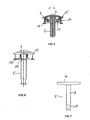
- FIG 1
- eine perspektivische Ansicht einer ersten Ausführungsform eines Tastenblocks gemäß der Erfindung,
- FIG 2
- eine Längsschnittdarstellung des Tastenblocks nach FIG 1 entlang der Bedienfläche,
- FIG 3
- eine Längsschnittdarstellung des Tastenblocks nach FIG 2 entlang der Ebene A-A,
- FIG 4
- eine Längsschnittdarstellung des Tastenblocks nach FIG 2 entlang der Ebene B-B,
- FIG 5
- eine Schnittdarstellung des Tastenblocks nach FIG 2 entlang der Ebene C-C,
- FIG 6
- eine Seitenansicht des Tastenblocks nach FIG 2
- FIG 7
- eine Ausführungsform eines Betätigungselementes für einen Tastenblock nach FIG 2,
- FIG 8
- eine Ausführungsform eines Rahmens für den Tastenblock nach FIG 2,
- FIG 9
- eine Draufsicht auf den Rahmen nach FIG 8,
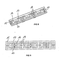
- FIG 10
- eine perspektivische Ansicht einer zweiten Ausführungsform des Tastenblocks gemäß der Erfindung,
- FIG 11
- eine Längsschnittdarstellung des Tastenblocks nach FIG 10
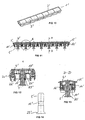
- FIG 12
- eine vergrößerte Darstellung des Ausschnitts K aus FIG 11,
- FIG 13
- eine Schnittdarstellung des Tastenblocks nach FIG 11 entlang der Ebene D-D,
- FIG 14
- eine Ausführungsform eines Betätigungselements des Tastenblocks nach FIG 11
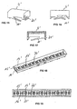
- FIG 15
- eine Ausführungsform einer Tastenkappe des Tastenblocks gemäß der Erfindung mit zwei angeformten Federbeinen,
- FIG 16
- eine Seitenansicht der Tastenkappe nach FIG 15,
- FIG 17
- eine Längsschnittdarstellung der Tastenkappe nach FIG 15,
- FIG 18
- eine Ausführungsform eines Rahmens für den Tastenblock nach FIG 11,
- FIG 19
- eine Draufsicht auf den Rahmen nach FIG 18.
- FIG. 1
- a perspective view of a first embodiment of a keypad according to the invention,
- FIG. 2
- 1 is a longitudinal sectional view of the keypad according to FIG. 1 along the operating surface;
- FIG. 3
- 3 is a longitudinal sectional view of the keypad according to FIG. 2 along the plane AA;
- FIG. 4
- FIG. 3 is a longitudinal sectional view of the keypad of FIG. 2 taken along the plane BB; FIG.
- FIG. 5
- a sectional view of the keypad of FIG 2 along the plane CC,
- FIG. 6
- a side view of the keypad of FIG. 2
- FIG. 7
- an embodiment of an actuating element for a keypad according to FIG. 2,
- FIG. 8
- an embodiment of a frame for the keypad of FIG 2,
- FIG. 9
- a top view of the frame of FIG 8,
- FIG. 10
- a perspective view of a second embodiment of the keypad according to the invention,
- FIG. 11
- a longitudinal sectional view of the keypad of FIG 10th
- FIG. 12
- an enlarged view of the detail K of FIG 11,
- FIG. 13
- a sectional view of the keypad of FIG 11 along the plane DD,
- FIG. 14
- an embodiment of an actuating element of the keypad of FIG 11
- FIG. 15
- an embodiment of a key cap of the keypad according to the invention with two molded struts,
- FIG. 16
- a side view of the key cap of FIG 15,
- FIG. 17
- a longitudinal sectional view of the key cap of FIG 15,
- FIG. 18
- an embodiment of a frame for the keypad of FIG 11,
- FIG. 19
- a plan view of the frame of FIG 18.
Einander entsprechende Teile und Größen sind in den FIG 1 bis 19 mit denselben Bezugszeichen versehen. Corresponding parts and sizes are shown in FIGS to 19 provided with the same reference numerals.
FIG 1 bis FIG 9 zeigen eine erste vorteilhafte Ausführungsform eines Tastenblocks gemäß der Erfindung.1 to 9 show a first advantageous embodiment a keypad according to the invention.
Der Tastenblock 1 in FIG 1 besteht aus einem Rahmen 2 der
drei in Reihe angeordnete, rechteckige Tasten 3 umschließt.
Der Tastenblock 1 ist jedoch nicht auf drei Tasten 3 beschränkt,
sondern um eine beliebige Anzahl von Tasten 3 erweiterbar.
Der gesamte Tastenblock 1 kann in einen Durchbruch
in einer vorzugsweise aus Glas, Edelstahl oder Aluminium
gefertigten Bedienfläche eines Haushaltsgerätes eingesetzt
werden.The keypad 1 in Figure 1 consists of a
FIG 2 und FIG 3 zeigen die einzelnen Komponenten des Tastenblocks
1. In dem rechteckigen Rahmen 2 sind die Tastenkappen
4 und die Betätigungselemente 5 geführt. Jede Tastenkappe
4 und jedes Betätigungselement 5 wird im Rahmen
separat geführt. An den Seiten der Tastenkappen 4, die auch
an die benachbarten Tasten angrenzen können, sind Schnapphaken
6 vorgesehen. Mit Hilfe der Schnapphaken 6 werden die
Tastenkappen 4 mit dem Rahmen 2 verrastet. Der maximale Hub
der Tastenkappen 4 ist durch den freien Weg zwischen dem
Abschluss der Seitenflächen der Tastenkappen 4 in Betätigungsrichtung
und dem Rahmen 2 festgelegt. Die Betätigungselemente
5 sind als T-Profil ausgeführt, wobei sich die
Querstreben 7 der T-förmigen Betätigungselemente 5 in die
Längsrichtung der Tastenkappen 4 erstrecken. Die Betätigungselemente
5 sind nicht mit den Tastenkappen 4 verbundden.
Die Längsstreben 8 der Betätigungselemente 5 sind mit
der elektronischen Schalteinheit 9 verrastet. Der rechteckige
Rahmen 2 weist in der Regel an seiner schmalen Außenseite
Schnapphaken 10 auf, die dazu dienen, den gesamten
Tastenblock 1 in der Bedienfläche des Haushaltsgerätes zu
fixieren. Die Tastenkappen 4 befinden sich in FIG. 3 in einer
Ausgangsposition. Die Betätigungselemente 5 können an
den Tastenkappen 4 anliegen oder eine andere Stellung zwischen
den Tastenkappen 4 und dem Schaltelement (hier nicht
dargestellt) der elektrischen Schalteinheit 9 einnehmen.FIG 2 and FIG 3 show the individual components of the keypad
1. In the
FIG 4 zeigt einen Schnitt entlang der Ebene B-B in FIG 2.
An die Tastenkappen 4 sind an die Seiten, die ausschließlich
an den Rahmen 2 angrenzen, in diesem Fall die Längsseiten,
Federbeine 11 angeformt, die von der Mitte der
Längsseite diagonal zu den äußeren Ecken verlaufen und auf
dem Rahmen 2 aufliegen. Durch Betätigen der Tastenkappe 4
werden die Federbeine 11 verformt, wodurch eine Spannung
aufgebaut wird (FIG 4, linke Taste). Wird die Tastenkappe 4
freigegeben, entspannen sich die Federbeine 11 bzw. nehmen
ihre ursprüngliche Form an und die Tastenkappe 4 wird durch
die freiwerdende Kraft in ihre Ausgangsposition zurückgestellt.
Die Federbeine 11 können in der Ausgangsposition
bereits vorgespannt bzw. leicht verformt sein. Dadurch
lässt sich eine gleichmäßige Höhe aller Tastenkappen 4 erreichen,
da diese nach außen gedrückt werden.4 shows a section along the plane B-B in FIG. 2
To the
Die Schnittdarstellung des Tastenblocks in FIG 5 zeigt,
dass am Rahmen 2 neben den Schnapphaken 10 zusätzlich Nasen
12 angebracht sind, die dazu dienen den Rahmen 2 in dem
Durchbruch in der Bedienfläche des Haushaltsgerätes zu fixieren
und gleichmäßig an die Bedienfläche anzudrücken. Die
Anordnung der Schnapphaken 10 und Nasen 12 am Rahmen 2 ist
in FIG 6 dargestellt.The sectional view of the keypad in FIG. 5 shows
that on the
FIG 7 zeigt eine mögliche Ausführungsform eines Betätigungselementes
5. Das Betätigungselement 5 ist als T-Profil
ausgebildet oder zumindest in einem Schnitt T-förmig. Über
die Querstrebe 7 können bei seitlicher Betätigung der Taste
die Druckkräfte in die Mitte abgeleitet werden. Die Längsstrebe
8 kann rund oder eckig ausgebildet sein und weist an
dem, vom Tastenblock abgewandten Ende ein Rastmittel 13 in
Form einer umlaufenden Vertiefung auf, die mit den korrespondierenden
Rastmitteln 25 der elektrischen Schalteinheit
9 in Eingriff kommt (vgl. FIG 3).7 shows a possible embodiment of an
Der rechteckige Rahmen 2 des Tastenblocks 1 umfasst einen
Rand 14, der die Tastenkappen 4 umschließt und an dem die
Nasen 12 und Schnapphaken 10 zur Befestigung des Tastenblocks
1 in der Bedienfläche angebracht sind (vgl. FIG 8
und FIG 5). An dem mit den Tastenkappen abschließenden Ende
ist der Rand 14 um 90° nach außen gebogenen, wodurch ein
umlaufender Sims 15 entsteht (vgl. FIG 9 und FIG 5). Der
umlaufende Sims 15 liegt auf der Oberfläche der Bedienfläche
auf und bildet so einen sauberen Abschluss des Tastenblocks
1. Die Höhe des Rands 14 entspricht in der Regel der
Dicke der Bedienfläche.The
FIG 9 zeigt, dass die Längsseiten des Rands 14 an der der
elektronischen Schalteinrichtung 9 zugewandten Seite mit
Querverbindungen 16 verbunden sind. Die Anzahl der Querverbindungen
16 entspricht der Anzahl der Tasten 3. Jede Querverbindungen
16 trägt einen Führungsrahmen 17 zur Führung
einer Tastenkappe 4 im Rahmen 2. Der Führungsrahmen 17 ist
im Wesentlichen rechteckig und niedriger als der Rand 14
ausgeführt. Die Abmessungen des Führungsrahmens 17 sind abhängig
von der eingesetzten Tastenkappe 4. weiterhin weist
der Führungsrahmen 17 an den gegenüberliegenden schmalen
Seiten, Fenster oder Vorsprünge 18 auf, in die die Schnapphaken
6 der Tastenkappen 4 einrasten, die den Führungsrahmen
17 umschließen.9 shows that the longitudinal sides of the
Der Führungsrahmen 17 weist an jeder Ecke, seitlich verjetzt
zu den Ecken jeweils zwei Ausbuchtungen 19 in Richtung
des Randes 14 bzw. des angrenzenden Führungsrahmens 17
auf. Diese Ausbuchtungen 19 liegen an der Innenseite der
Tastenkappen 4 an bzw. die Tastenkappen 4 werden entlang
der Ausbuchtungen 19 geführt. Das hat zur Folge, dass sich
die Tastenkappen nicht verdrehen können und stets senkrecht
zueinander stehen.The
Wie FIG 9 zeigt sind in der Mitte der Querverbindungen 16
Öffnungen 20 angebracht. Durch diese Öffnungen 20 werden
die Längsstreben 8 der Betätigungselemente 5 geführt.As FIG 9 shows are in the middle of the cross-connections sixteenth
Der Tastenblock 1 kann in der im Folgenden beschriebenen
Reihenfolge montiert werden. Zunächst wird der Rahmen 2 im
Durchbruch in der Bedienfläche eingesetzt und mit Hilfe der
Schnapphaken und Nasen fixiert. Als nächstes werden die Betätigungselemente
5 von außen durch den Rahmen 2 hindurch
mit der elektrischen Schalteinheit in Eingriff gebracht.
Anschließend können die Tastenkappen 4 auf die Führungsrahmen
17 aufgesetzt werden. Die Fixierung der Tastenkappen
erfolgt durch Einschnappen der Schnapphaken 6 in den Fenstern
oder Vorsprüngen 18 in den Führungsrahmen 17.The keypad 1 can be described below
Order to be assembled. First, the
Wird nun die Tastenkappe 4 in Richtung des Betätigungselementes
5 bewegt, so wird beim Zusammenwirken von Tastenkappe
4 und Betätigungselement 5 dieses in dieselbe Richtung
mitbewegt, bis es am Schaltelement der elektrischen schalteinrichtung
9 anliegt. Die durch weiteres Drücken auf das
Betätigungselement 5 beaufschlagte Kraft wird über die
Längsstrebe 7 in Betätigungsrichtung auf das Schaltelement
der elektrischen Schalteinheit 9 übertragen, wodurch der
Schaltvorgang ausgelöst wird. Der maximale Hub des Betätigungselements
5 und damit auch die maximale auf das Schaltelement
einwirkende Kraft wird durch die umlaufende Vertiefung
des Rastmittels 13 des Betätigungselements 5 und das
darin eingreifende Rastmittel 25 der elektrischen Schalteinheit
9 begrenzt. Wird die Tastenkappe 4 wieder freigegeben,
wird sie aufgrund der durch die Federbeine 11 erzeugten
Rückstellkraft vom Betätigungselement 5 weg nach außen
bewegt. Das Betätigungselement 5 kann in Kontakt mit dem
Schaltelement verbleiben oder eine andere Stellung zwischen
Schaltelement und Tastenkappe 4 einnehmen. Erneutes Drücken
der Tastenkappe 4 löst dann einen weiteren Schaltvorgang
aus.Now, the
FIG 10 bis FIG 19 zeigen eine zweite Ausführungsform des Tastenblocks gemäß der Erfindung.FIGS. 10 to 19 show a second embodiment of the invention Keypads according to the invention.
Der Tastenblock 1' in FIG 10 besteht aus einem Rahmen 2'
der sieben in Reihe angeordnete, rechteckige Tasten 3' umschließt.
Der Tastenblock 1' ist nicht auf sieben Tasten
beschränkt, sondern um eine beliebige Anzahl von Tasten erweiterbar.The keypad 1 'in FIG. 10 consists of a
In FIG 11 und FIG 12 sind die Komponenten des Tastenblocks
1' dargestellt. Wie bei der ersten Ausführungsform sind
auch in dieser zweiten Ausführungsform in dem rechteckigen
Rahmen 2' die Tastenkappen 4' und die Betätigungselemente
5' geführt. Jede Tastenkappe 4' und jedes Betätigungselement
5' wird im Rahmen separat geführt. Die Betätigungselemente
5' sind nicht mit den Tastenkappen 4' verbunden. Im
Gegensatz zur ersten Ausführungsform sind hier die Betätigungselemente
5' nicht mit der elektrischen Schalteinheit
(hier nicht gezeigt) sondern mit dem Rahmen 2' verrastet.In FIG. 11 and FIG. 12, the components of the keypad are shown
1 'shown. As in the first embodiment
also in this second embodiment in the rectangular
Frame 2 'the keycaps 4' and the actuators
5 'out. Each keycap 4 'and each actuator
5 'is managed separately in the frame. The actuators
5 'are not connected to the
Der rechteckige Rahmen 2' weist an seiner schmalen Außenzweite Schnapphaken 10' und Nasen 12' auf, die dazu dienen, den gesamten Tastenblock 1' in der Bedienfläche des Haushaltsgerätes zu fixieren und anzudrücken (vgl. FIG 12 und FIG 13). The rectangular frame 2 'has its narrow outer second Snap hooks 10 'and noses 12', which serve the entire keypad 1 'in the control surface of the household appliance to fix and press (see FIG 12 and FIG. 13).
FIG 15 bis 17 zeigen eine Tastenkappe 4' für den Einsatz in den Tastenblock 1'. An den Längsseiten der Tastenkappe 4' ist je ein Federbein 11' angeformt, das von einer Ecke der Längsseite aus zur diagonal gegenüberliegenden Ecke verläuft. Die Federbeine 11' verlaufen entgegengesetzt zueinander, dadurch wird die Tastenkappe 4' gleichmäßig nach außen gepresst. Die Federbeine 11' können aber auch in dieselbe Richtung gerichtet sein. Durch Betätigen der Tastenkappe 4' werden die Federbeine 11' gegen den Rahmen 2' als Widerlager gespannt. Die Federbeine 11' können in der Ausgangsposition wiederum vorgespannt sein, wodurch eine gleichmäßige Höhe aller Tastenkappen 4' erreicht wird. An den Seiten der Tastenkappen 4', die auch an die benachbarten Tasten angrenzen können, sind Fenster 21' eingebracht die mit am Rahmen 2' angebrachten Schnapphaken 22' lösbar verbunden sind (vgl. auch FIG 12).FIGS. 15 to 17 show a key cap 4 'for use in the keypad 1 '. On the long sides of the key cap 4 ' is ever a strut 11 'formed from a corner of the Long side out to the diagonally opposite corner. The struts 11 'are opposite to each other, As a result, the key cap 4 'evenly outward pressed. But the struts 11 'can also in the same Directed direction. By pressing the button cap 4 'are the struts 11' against the frame 2 'as Abutment cocked. The struts 11 'can in the starting position be biased again, creating a uniform height of all keycaps 4 'is achieved. At the sides of the keycaps 4 ', which also to the adjacent Buttons can be adjacent, windows 21 'are introduced the with the frame 2 'attached snap hook 22' solvable are connected (see also FIG 12).
Der rechteckige Rahmen 2' des Tastenblocks 1' nach FIG 11 umfasst einen Rand 14', der die Tastenkappen 4' umschließt und an dem die Nasen 12' und Schnapphaken 10' zur Befestigung des Tastenblocks in der Bedienfläche angebracht sind (vgl. FIG. 18, FIG. 11 und 13). An dem mit den. Tastenkappen abschließenden Ende ist der Rand 14' mit einem umlaufenden Sims 15' abgeschlossen (vgl. FIG 19 und FIG 11), der auf der Oberfläche der Bedienfläche aufliegt.The rectangular frame 2 'of the keypad 1' of FIG 11 includes a rim 14 'which encloses the keycaps 4' and at which the lugs 12 'and snap hook 10' for attachment of the keypad are mounted in the control surface (See Figure 18, Figures 11 and 13). At the with the. keycaps final end is the edge 14 'with a circumferential Sims 15 'completed (see FIG 19 and FIG 11), the on the surface of the operating surface rests.
FIG 19 zeigt, dass die Längsseiten des Rands 14' an seiner der Elektronik zugewandten Seite mit Querverbindungen 16' verbunden sind, die einen Führungsrahmen 17' tragen über den jeweils eine Tastenkappe 4' im Rahmen 2' geführt wird. Der Führungsrahmen 17' ist im Wesentlichen rechteckig und niedriger als der Rand 14' ausgeführt. Die Abmessungen des Führungsrahmens 17' sind abhängig von der eingesetzten Tastenkappe 4'. Weiterhin weist der Führungsrahmen 17' an den gegenüberliegenden schmalen Seiten, Schnapphaken 22' auf, die in die Tastenkappen 4' einrasten können.FIG. 19 shows that the longitudinal sides of the edge 14 'on its the electronics facing side with cross connections 16 ' are connected, which carry a guide frame 17 'over in each case a key cap 4 'in the frame 2' is performed. The guide frame 17 'is substantially rectangular and lower than the edge 14 'executed. The dimensions of the Guide frame 17 'are dependent on the key cap used 4 '. Furthermore, the guide frame 17 'to the opposite narrow sides, snap hooks 22 'on, which can snap into the keycaps 4 '.
FIG 18 und FIG 12 zeigen, dass an der, der Tastenkappe 4' zugewandten Oberfläche des Führungsrahmens 17' in der Mitte Öffnungen 20' angebracht sind, in denen die Betätigungselemente 5' eingeführt sind. An der der elektrischen Schalteinheit zugewandten Seite der Öffnungen 20' erstreckt sich ein Verrastrahmen 24' in Richtung der elektrischen Schalteinheit. Der Verrastrahmen 24' endet in Rastmitteln 25', die in das als Vertiefung ausgebildete Rastmittel 13' des Betätigungselements 5' eingreifen (vgl. FIG 12 und FIG 13).FIG. 18 and FIG. 12 show that at 'the key cap 4' facing surface of the guide frame 17 'in the middle Openings 20 'are mounted, in which the actuators 5 'are introduced. At the electrical switching unit facing side of the openings 20 'extends a Verrastrahmen 24 'in the direction of the electrical switching unit. The Verrastrahmen 24 'ends in locking means 25', in the recess formed as a detent means 13 'of the Actuate 5 'engage (see FIG 12 and FIG 13).
Der maximale Hub des Betätigungselements 5' und damit auch die maximale auf das Schaltelement (hier nicht gezeigt) einwirkende Kraft wird bei dieser zweiten Ausführungsform durch das Rastmittel 13' des Betätigungselements 5' und die darin eingreifenden Rastmittel 25' begrenzt. Das Betätigungselement hat an seiner dem Schaltelement der elektrischen Schalteinheit zugewandten Seite eine Verbreiterung 23' die im Durchmesser größer ist, als das restliche Betätigungselement 5' (vgl. auch FIG 14). Die Verbreiterung ermöglicht es auch bei einem leicht versetzten Schaltelement die Kraft zum Auslösen des Schaltvorganges auf dieses zu übertragen.The maximum stroke of the actuating element 5 'and thus also the maximum on the switching element (not shown here) acting force is in this second embodiment by the latching means 13 'of the actuating element 5' and the limited engaging latching means 25 '. The actuator has at its the switching element of the electric Switching unit facing side a widening 23 'which is larger in diameter than the rest of the actuator 5 '(see also FIG. The broadening allows it also with a slightly offset switching element the force to trigger the switching operation on this transfer.
Der Tastenblock 1' gemäß FIG 10 bis 19 kann komplett vormontiert werden. Der vormontierte Tastenblock 1' kann dann mit einem Handgriff in die Bedienfläche des Haushaltsgerätes eingesetzt werden, was den Fertigungsprozess deutlich verkürzt. The keypad 1 'shown in FIG 10 to 19 can be completely pre-assembled become. The preassembled keypad 1 'can then with a handle in the control surface of the household appliance are used, which makes the manufacturing process clear shortened.
- 1, 1'1, 1 '
- Tastenblockkeypad
- 2, 2'2, 2 '
- Rahmenframe
- 3, 3'3, 3 '
- Tastebutton
- 4, 4'4, 4 '
- Tastenkappekeycap
- 5, 5'5, 5 '
- Betätigungselementactuator
- 6, 6'6, 6 '
- Schnapphakensnap hooks
- 77
- Querstrebecrossmember
- 88th
- Längsstrebelongitudinal strut
- 99
- elektrische Schalteinheitelectrical switching unit
- 10, 10'10, 10 '
- Schnapphakensnap hooks
- 11, 11'11, 11 '
- FederbeineSuspensions
- 12, 12'12, 12 '
- Nasennose
- 13, 13'13, 13 '
- Rastmittellatching means
- 14. 14'14. 14 '
- Randedge
- 15, 15'15, 15 '
- Simsledge
- 16, 16'16, 16 '
- Querverbindungcross connection
- 17, 17'17, 17 '
- Führungsrahmenguide frame
- 1616
- Fenster oder VorsprungWindow or projection
- 1919
- Ausbuchtungbulge
- 20, 20'20, 20 '
- Öffnungopening
- 21'21 '
- Fensterwindow
- 22'22 '
- Schnapphakensnap hooks
- 23'23 '
- Verbreiterungwidening
- 24'24 '
- VerrastrahmenVerrastrahmen
- 25, 25'25, 25 '
- Rastmittellatching means
Claims (15)
- Keypad (1) for insertion in an operating surface of a domestic appliance, in particular a screen composed of glass, special steel, aluminium or materials with similar properties comprisinga) at least one key (3) comprising
a key cap (4) and
an actuating element (5), which is disposed or may be disposed between the key cap and an electric switching unit of the domestic appliance and upon actuation of the key cap cooperates therewith and with the electric switching unit to trigger a switching event,b) at least one spring element (11) which upon actuation of the key provides a restoring force for putting the key cap back, andc) a frame (2) in which the at least one key is guided, whereind) the key cap abuts a corresponding active area of the actuating element upon actuation via an active area, and transmits a force to the actuating element in the actuating direction, and whereine) the key cap and actuating element are not connected together at least at their corresponding active areas, characterised in that for each key a separate guide frame is formed and regions of the surface of the guide frame abut corresponding regions of the inner face of the side faces of the key cap. - Keypad according to claim 1, wherein the at least one spring element is not connected in terms of force to the actuating element.
- Keypad according to claim 1 or claim 2, wherein the at least one spring element is integrally formed with the key cap and abuts the frame.
- Keypad according to one or more of claims 1 to 3, wherein the at least one spring element is biased in a starting position.
- Keypad according to one or more of the preceding claims, wherein the at least one spring element is a telescopic leg integrally formed with the key cap.
- Keypad according to claim 5, wherein four telescopic legs are integrally formed on the key caps.
- Keypad according to claim 5, wherein two telescopic legs are integrally formed on the key cap.
- Keypad according to one or more of the preceding claims, wherein the frame is inserted or is insertable together with the keys guided therein into a perforation in the operating surface.
- Keypad according to claim 8, wherein on the frame means are formed for the fixing of the keypad in the perforation.
- Keypad according to one or more of the preceding claims, wherein the position of the actuating element may be varied with respect to the key cap in the actuating direction and/or perpendicular to the actuating direction within a respectively specified range of tolerances.
- Keypad according to one or more of the preceding claims, wherein on the actuating element a catch means is formed which comprises recesses or projections, preferably channels, grooves, lugs or hooks.
- Keypad according to one or more of the preceding claims, wherein the actuating element is detachably connected via the catch means to corresponding catch means on the electric switching unit.
- Keypad according to one or more of the preceding claims, wherein the actuating element is formed T-shaped at least in section.
- Keypad according to one or more of claims 1 to 10 and 11, wherein the actuating element is detachably connected via the catch means to corresponding catch means on the frame.
- Keypad according to claim 13, wherein the actuating element has on the end cooperating with the electric switching unit a widening which has a larger diameter than the section of the actuating element bordering the widening.
Applications Claiming Priority (2)
| Application Number | Priority Date | Filing Date | Title |
|---|---|---|---|
| DE10316934A DE10316934B4 (en) | 2003-04-12 | 2003-04-12 | Keypad for insertion into a control surface of a household appliance |
| DE10316934 | 2003-04-12 |
Publications (2)
| Publication Number | Publication Date |
|---|---|
| EP1467390A1 EP1467390A1 (en) | 2004-10-13 |
| EP1467390B1 true EP1467390B1 (en) | 2005-11-09 |
Family
ID=32864467
Family Applications (1)
| Application Number | Title | Priority Date | Filing Date |
|---|---|---|---|
| EP03029681A Expired - Lifetime EP1467390B1 (en) | 2003-04-12 | 2003-12-23 | Key-pad for the control panel of a household appliance |
Country Status (5)
| Country | Link |
|---|---|
| EP (1) | EP1467390B1 (en) |
| AT (1) | ATE309611T1 (en) |
| DE (2) | DE10316934B4 (en) |
| DK (1) | DK1467390T3 (en) |
| ES (1) | ES2252612T3 (en) |
Families Citing this family (8)
| Publication number | Priority date | Publication date | Assignee | Title |
|---|---|---|---|---|
| DE102005017255A1 (en) * | 2005-04-14 | 2006-10-19 | Leopold Kostal Gmbh & Co. Kg | Key arrangement for e.g. electronic device, has face plate encompassing key cap and guiding units formed on side walls of cap and at edge regions of face plate, where distances between side surfaces of cap and face plate are smaller |
| DE502006008862D1 (en) | 2005-04-14 | 2011-03-24 | Kostal Leopold Gmbh & Co Kg | Button arrangement for an electrical or electronic device in a motor vehicle |
| DE102005017254A1 (en) * | 2005-04-14 | 2006-10-19 | Leopold Kostal Gmbh & Co. Kg | Key arrangement for e.g. electronic device, has face plate encompassing key cap and guiding units formed on side walls of cap and at edge regions of face plate, where distances between side surfaces of cap and face plate are smaller |
| JP2007316320A (en) | 2006-05-25 | 2007-12-06 | Funai Electric Co Ltd | Projector |
| DE102007045866B3 (en) * | 2007-09-25 | 2008-10-23 | Albrecht Jung Gmbh & Co. Kg | Actuating buttons assembly arrangement for cover part of electrical installation device, has locking unit formed on buttons, and another locking unit formed on cover part, where locking units stay in effective connection with each other |
| DE102008041966A1 (en) | 2008-09-10 | 2010-03-11 | BSH Bosch und Siemens Hausgeräte GmbH | Domestic appliance i.e. stove, has actuation unit movably retained at housing unit by connection unit and including operating medium pressure-receiving surface, and protection unit connected to connection unit |
| EP2282318B1 (en) | 2009-07-29 | 2016-06-29 | Electrolux Home Products Corporation N.V. | Push button switch assembly |
| DE102011119943A1 (en) * | 2011-12-01 | 2013-06-06 | Liebherr-Aerospace Lindenberg Gmbh | actuator |
Family Cites Families (6)
| Publication number | Priority date | Publication date | Assignee | Title |
|---|---|---|---|---|
| DE19634051C1 (en) * | 1996-08-23 | 1997-08-28 | Telefunken Microelectron | Pushbutton switch arrangement mounted on a circuit board |
| US5817997A (en) * | 1997-01-24 | 1998-10-06 | Silicon Graphics, Inc. | Power switch plunger mechanism |
| DE19739575C2 (en) * | 1997-09-10 | 2003-10-16 | Aeg Hausgeraete Gmbh | Function block, in particular key block, for the control surface of a device and control surface of a device with such a function block |
| DE19831850A1 (en) * | 1998-07-16 | 2000-01-20 | Aeg Hausgeraete Gmbh | Program selection switch operating element for domestic electrical appliance, e.g. dishwashing machine, has nonconductive part brought into contact with switch fitted with electrically conductive contact surface |
| DE19858982C1 (en) * | 1998-12-19 | 2000-04-13 | Ellenberger & Poensgen | Electrical switch appliance for fitting in a mounting plate in a panel has an upper casing with a support flange for a switch and an elastomer one-piece plane element sealing the upper and lower casing parts. |
| EP1288983A3 (en) * | 2001-09-04 | 2004-06-16 | Siemens Aktiengesellschaft | Electronic device, keyboard for an electronic device and method for positioning a keyboard in an electronic device |
-
2003
- 2003-04-12 DE DE10316934A patent/DE10316934B4/en not_active Expired - Fee Related
- 2003-12-23 ES ES03029681T patent/ES2252612T3/en not_active Expired - Lifetime
- 2003-12-23 AT AT03029681T patent/ATE309611T1/en not_active IP Right Cessation
- 2003-12-23 DE DE50301612T patent/DE50301612D1/en not_active Expired - Lifetime
- 2003-12-23 DK DK03029681T patent/DK1467390T3/en active
- 2003-12-23 EP EP03029681A patent/EP1467390B1/en not_active Expired - Lifetime
Also Published As
| Publication number | Publication date |
|---|---|
| EP1467390A1 (en) | 2004-10-13 |
| DK1467390T3 (en) | 2006-02-13 |
| DE10316934A1 (en) | 2004-10-28 |
| ES2252612T3 (en) | 2006-05-16 |
| DE10316934B4 (en) | 2007-12-13 |
| ATE309611T1 (en) | 2005-11-15 |
| DE50301612D1 (en) | 2005-12-15 |
Similar Documents
| Publication | Publication Date | Title |
|---|---|---|
| DE19853438A1 (en) | Multi-directional push button switch arrangement | |
| DE202006019447U1 (en) | Touch-sensitive slide control for operating device, has touch-sensitive control strip for absolute and/or relative inputting of control value, and key switch arranged at strip, where switch changes value based on duration of its operation | |
| DE2858237C2 (en) | ||
| EP1467390B1 (en) | Key-pad for the control panel of a household appliance | |
| DE2301853C3 (en) | Push button switch | |
| DE19634051C1 (en) | Pushbutton switch arrangement mounted on a circuit board | |
| WO2012168326A1 (en) | Operating panel for a vehicle component | |
| DE10309516B3 (en) | Control button block incorporated in operating panel for domestic appliance e.g. cooking hob or baking oven, has return spring for each button cover guided via elastomer frame attached to operating panel | |
| EP1482527B1 (en) | Push button switch | |
| DE29611275U1 (en) | Switching device for telephone sets | |
| DE19836793C2 (en) | Control element for the selective establishment of electrical contacts | |
| DE4213054B4 (en) | key arrangement | |
| DE4334494C1 (en) | Keycard switch | |
| EP3736930B1 (en) | Tactile sensor with at least one operating rocker button | |
| EP0944104A1 (en) | Large push button for a key board, which covers a plurality of small banks of keys | |
| EP1501108B1 (en) | Multidirectional switch | |
| DE3242821A1 (en) | CAP FOR A BLADE SWITCH | |
| DE19527093C2 (en) | Button arrangement | |
| EP1715497B1 (en) | Operating device with switching mat | |
| DE2462034C3 (en) | Key suitable for assembling keyboards | |
| DE10349592B4 (en) | Keypad for insertion into a panel and mounting arrangement of a keypad on a panel | |
| DE10354043B3 (en) | Push button block for domestic appliance operating panel has operating element(s) that interacts with switching device if cap operated to trigger switching process(es); operating element has external diameter decreasing towards cap | |
| DE7502213U (en) | Push button switch | |
| DE102017214533B3 (en) | Operating device for a motor vehicle, in particular for a motor vehicle, and motor vehicle | |
| DE4117771A1 (en) | Pushbutton device for communications peripheral appts. - has pushbutton head having U=shaped bottom part and replaceable cover cap carrying pushbutton symbol |
Legal Events
| Date | Code | Title | Description |
|---|---|---|---|
| PUAI | Public reference made under article 153(3) epc to a published international application that has entered the european phase |
Free format text: ORIGINAL CODE: 0009012 |
|
| AK | Designated contracting states |
Kind code of ref document: A1 Designated state(s): AT BE BG CH CY CZ DE DK EE ES FI FR GB GR HU IE IT LI LU MC NL PT RO SE SI SK TR |
|
| AX | Request for extension of the european patent |
Extension state: AL LT LV MK |
|
| 17P | Request for examination filed |
Effective date: 20040818 |
|
| 17Q | First examination report despatched |
Effective date: 20041129 |
|
| GRAP | Despatch of communication of intention to grant a patent |
Free format text: ORIGINAL CODE: EPIDOSNIGR1 |
|
| AKX | Designation fees paid |
Designated state(s): AT BE BG CH CY CZ DE DK EE ES FI FR GB GR HU IE IT LI LU MC NL PT RO SE SI SK TR |
|
| GRAS | Grant fee paid |
Free format text: ORIGINAL CODE: EPIDOSNIGR3 |
|
| GRAA | (expected) grant |
Free format text: ORIGINAL CODE: 0009210 |
|
| AK | Designated contracting states |
Kind code of ref document: B1 Designated state(s): AT BE BG CH CY CZ DE DK EE ES FI FR GB GR HU IE IT LI LU MC NL PT RO SE SI SK TR |
|
| PG25 | Lapsed in a contracting state [announced via postgrant information from national office to epo] |
Ref country code: FI Free format text: LAPSE BECAUSE OF FAILURE TO SUBMIT A TRANSLATION OF THE DESCRIPTION OR TO PAY THE FEE WITHIN THE PRESCRIBED TIME-LIMIT Effective date: 20051109 Ref country code: CZ Free format text: LAPSE BECAUSE OF FAILURE TO SUBMIT A TRANSLATION OF THE DESCRIPTION OR TO PAY THE FEE WITHIN THE PRESCRIBED TIME-LIMIT Effective date: 20051109 Ref country code: EE Free format text: LAPSE BECAUSE OF FAILURE TO SUBMIT A TRANSLATION OF THE DESCRIPTION OR TO PAY THE FEE WITHIN THE PRESCRIBED TIME-LIMIT Effective date: 20051109 Ref country code: TR Free format text: LAPSE BECAUSE OF FAILURE TO SUBMIT A TRANSLATION OF THE DESCRIPTION OR TO PAY THE FEE WITHIN THE PRESCRIBED TIME-LIMIT Effective date: 20051109 Ref country code: SI Free format text: LAPSE BECAUSE OF FAILURE TO SUBMIT A TRANSLATION OF THE DESCRIPTION OR TO PAY THE FEE WITHIN THE PRESCRIBED TIME-LIMIT Effective date: 20051109 Ref country code: RO Free format text: LAPSE BECAUSE OF FAILURE TO SUBMIT A TRANSLATION OF THE DESCRIPTION OR TO PAY THE FEE WITHIN THE PRESCRIBED TIME-LIMIT Effective date: 20051109 Ref country code: IE Free format text: LAPSE BECAUSE OF FAILURE TO SUBMIT A TRANSLATION OF THE DESCRIPTION OR TO PAY THE FEE WITHIN THE PRESCRIBED TIME-LIMIT Effective date: 20051109 Ref country code: SK Free format text: LAPSE BECAUSE OF FAILURE TO SUBMIT A TRANSLATION OF THE DESCRIPTION OR TO PAY THE FEE WITHIN THE PRESCRIBED TIME-LIMIT Effective date: 20051109 |
|
| REG | Reference to a national code |
Ref country code: GB Ref legal event code: FG4D Free format text: NOT ENGLISH |
|
| REG | Reference to a national code |
Ref country code: CH Ref legal event code: EP |
|
| REG | Reference to a national code |
Ref country code: CH Ref legal event code: NV Representative=s name: TROESCH SCHEIDEGGER WERNER AG |
|
| PGFP | Annual fee paid to national office [announced via postgrant information from national office to epo] |
Ref country code: AT Payment date: 20051213 Year of fee payment: 3 |
|
| PGFP | Annual fee paid to national office [announced via postgrant information from national office to epo] |
Ref country code: ES Payment date: 20051214 Year of fee payment: 3 |
|
| REG | Reference to a national code |
Ref country code: IE Ref legal event code: FG4D Free format text: LANGUAGE OF EP DOCUMENT: GERMAN |
|
| REF | Corresponds to: |
Ref document number: 50301612 Country of ref document: DE Date of ref document: 20051215 Kind code of ref document: P |
|
| PG25 | Lapsed in a contracting state [announced via postgrant information from national office to epo] |
Ref country code: CY Free format text: LAPSE BECAUSE OF FAILURE TO SUBMIT A TRANSLATION OF THE DESCRIPTION OR TO PAY THE FEE WITHIN THE PRESCRIBED TIME-LIMIT Effective date: 20051223 |
|
| PG25 | Lapsed in a contracting state [announced via postgrant information from national office to epo] |
Ref country code: MC Free format text: LAPSE BECAUSE OF NON-PAYMENT OF DUE FEES Effective date: 20051231 Ref country code: BE Free format text: LAPSE BECAUSE OF NON-PAYMENT OF DUE FEES Effective date: 20051231 |
|
| PG25 | Lapsed in a contracting state [announced via postgrant information from national office to epo] |
Ref country code: LU Free format text: LAPSE BECAUSE OF NON-PAYMENT OF DUE FEES Effective date: 20060109 |
|
| PG25 | Lapsed in a contracting state [announced via postgrant information from national office to epo] |
Ref country code: GR Free format text: LAPSE BECAUSE OF FAILURE TO SUBMIT A TRANSLATION OF THE DESCRIPTION OR TO PAY THE FEE WITHIN THE PRESCRIBED TIME-LIMIT Effective date: 20060209 Ref country code: BG Free format text: LAPSE BECAUSE OF FAILURE TO SUBMIT A TRANSLATION OF THE DESCRIPTION OR TO PAY THE FEE WITHIN THE PRESCRIBED TIME-LIMIT Effective date: 20060209 |
|
| REG | Reference to a national code |
Ref country code: DK Ref legal event code: T3 |
|
| REG | Reference to a national code |
Ref country code: SE Ref legal event code: TRGR |
|
| GBT | Gb: translation of ep patent filed (gb section 77(6)(a)/1977) |
Effective date: 20060220 |
|
| PG25 | Lapsed in a contracting state [announced via postgrant information from national office to epo] |
Ref country code: PT Free format text: LAPSE BECAUSE OF FAILURE TO SUBMIT A TRANSLATION OF THE DESCRIPTION OR TO PAY THE FEE WITHIN THE PRESCRIBED TIME-LIMIT Effective date: 20060410 |
|
| PG25 | Lapsed in a contracting state [announced via postgrant information from national office to epo] |
Ref country code: HU Free format text: LAPSE BECAUSE OF FAILURE TO SUBMIT A TRANSLATION OF THE DESCRIPTION OR TO PAY THE FEE WITHIN THE PRESCRIBED TIME-LIMIT Effective date: 20060510 |
|
| REG | Reference to a national code |
Ref country code: ES Ref legal event code: FG2A Ref document number: 2252612 Country of ref document: ES Kind code of ref document: T3 |
|
| REG | Reference to a national code |
Ref country code: IE Ref legal event code: FD4D |
|
| ET | Fr: translation filed | ||
| PLBE | No opposition filed within time limit |
Free format text: ORIGINAL CODE: 0009261 |
|
| STAA | Information on the status of an ep patent application or granted ep patent |
Free format text: STATUS: NO OPPOSITION FILED WITHIN TIME LIMIT |
|
| 26N | No opposition filed |
Effective date: 20060810 |
|
| PG25 | Lapsed in a contracting state [announced via postgrant information from national office to epo] |
Ref country code: AT Free format text: LAPSE BECAUSE OF NON-PAYMENT OF DUE FEES Effective date: 20061223 |
|
| BERE | Be: lapsed |
Owner name: ELECTROLUX HOME PRODUCTS CORPORATION N.V. Effective date: 20051231 |
|
| REG | Reference to a national code |
Ref country code: ES Ref legal event code: FD2A Effective date: 20061226 |
|
| PG25 | Lapsed in a contracting state [announced via postgrant information from national office to epo] |
Ref country code: ES Free format text: LAPSE BECAUSE OF NON-PAYMENT OF DUE FEES Effective date: 20061226 |
|
| PGFP | Annual fee paid to national office [announced via postgrant information from national office to epo] |
Ref country code: CH Payment date: 20081218 Year of fee payment: 6 Ref country code: DK Payment date: 20081218 Year of fee payment: 6 Ref country code: NL Payment date: 20081219 Year of fee payment: 6 |
|
| PGFP | Annual fee paid to national office [announced via postgrant information from national office to epo] |
Ref country code: SE Payment date: 20081215 Year of fee payment: 6 |
|
| PGFP | Annual fee paid to national office [announced via postgrant information from national office to epo] |
Ref country code: GB Payment date: 20081223 Year of fee payment: 6 |
|
| REG | Reference to a national code |
Ref country code: NL Ref legal event code: V1 Effective date: 20100701 |
|
| EUG | Se: european patent has lapsed | ||
| REG | Reference to a national code |
Ref country code: CH Ref legal event code: PL |
|
| REG | Reference to a national code |
Ref country code: DK Ref legal event code: EBP |
|
| GBPC | Gb: european patent ceased through non-payment of renewal fee |
Effective date: 20091223 |
|
| PG25 | Lapsed in a contracting state [announced via postgrant information from national office to epo] |
Ref country code: LI Free format text: LAPSE BECAUSE OF NON-PAYMENT OF DUE FEES Effective date: 20091231 Ref country code: CH Free format text: LAPSE BECAUSE OF NON-PAYMENT OF DUE FEES Effective date: 20091231 Ref country code: NL Free format text: LAPSE BECAUSE OF NON-PAYMENT OF DUE FEES Effective date: 20100701 |
|
| PG25 | Lapsed in a contracting state [announced via postgrant information from national office to epo] |
Ref country code: GB Free format text: LAPSE BECAUSE OF NON-PAYMENT OF DUE FEES Effective date: 20091223 |
|
| PG25 | Lapsed in a contracting state [announced via postgrant information from national office to epo] |
Ref country code: DK Free format text: LAPSE BECAUSE OF NON-PAYMENT OF DUE FEES Effective date: 20100104 |
|
| PG25 | Lapsed in a contracting state [announced via postgrant information from national office to epo] |
Ref country code: SE Free format text: LAPSE BECAUSE OF NON-PAYMENT OF DUE FEES Effective date: 20091224 |
|
| REG | Reference to a national code |
Ref country code: FR Ref legal event code: CA Effective date: 20120116 |
|
| REG | Reference to a national code |
Ref country code: DE Ref legal event code: R082 Ref document number: 50301612 Country of ref document: DE Representative=s name: GERHARD BAUMGARTL, DE Ref country code: DE Ref legal event code: R082 Ref document number: 50301612 Country of ref document: DE Representative=s name: BAUMGARTL, GERHARD, DIPL.-ING.UNIV., DE |
|
| PGFP | Annual fee paid to national office [announced via postgrant information from national office to epo] |
Ref country code: FR Payment date: 20130130 Year of fee payment: 10 |
|
| REG | Reference to a national code |
Ref country code: FR Ref legal event code: ST Effective date: 20140829 |
|
| PG25 | Lapsed in a contracting state [announced via postgrant information from national office to epo] |
Ref country code: FR Free format text: LAPSE BECAUSE OF NON-PAYMENT OF DUE FEES Effective date: 20131231 |
|
| PGFP | Annual fee paid to national office [announced via postgrant information from national office to epo] |
Ref country code: DE Payment date: 20221213 Year of fee payment: 20 |
|
| PGFP | Annual fee paid to national office [announced via postgrant information from national office to epo] |
Ref country code: IT Payment date: 20221228 Year of fee payment: 20 |
|
| P01 | Opt-out of the competence of the unified patent court (upc) registered |
Effective date: 20230625 |
|
| REG | Reference to a national code |
Ref country code: DE Ref legal event code: R071 Ref document number: 50301612 Country of ref document: DE |