EP1467228B1 - Optoelektronische Zugangsabsicherung - Google Patents
Optoelektronische Zugangsabsicherung Download PDFInfo
- Publication number
- EP1467228B1 EP1467228B1 EP04001882A EP04001882A EP1467228B1 EP 1467228 B1 EP1467228 B1 EP 1467228B1 EP 04001882 A EP04001882 A EP 04001882A EP 04001882 A EP04001882 A EP 04001882A EP 1467228 B1 EP1467228 B1 EP 1467228B1
- Authority
- EP
- European Patent Office
- Prior art keywords
- light
- lobe
- light lobe
- transmitted light
- optoelectronic
- Prior art date
- Legal status (The legal status is an assumption and is not a legal conclusion. Google has not performed a legal analysis and makes no representation as to the accuracy of the status listed.)
- Expired - Lifetime
Links
- 230000005693 optoelectronics Effects 0.000 title claims abstract description 19
- 238000012544 monitoring process Methods 0.000 claims abstract description 3
- 230000003287 optical effect Effects 0.000 abstract description 8
- 230000004888 barrier function Effects 0.000 abstract description 2
- 230000005540 biological transmission Effects 0.000 abstract description 2
- 238000000926 separation method Methods 0.000 abstract 1
- 238000011156 evaluation Methods 0.000 description 5
- 230000005855 radiation Effects 0.000 description 4
- 229910000831 Steel Inorganic materials 0.000 description 2
- 230000001681 protective effect Effects 0.000 description 2
- 239000010959 steel Substances 0.000 description 2
- 208000003443 Unconsciousness Diseases 0.000 description 1
- 230000006735 deficit Effects 0.000 description 1
- 230000000694 effects Effects 0.000 description 1
- 238000010616 electrical installation Methods 0.000 description 1
- 230000005670 electromagnetic radiation Effects 0.000 description 1
- 230000007613 environmental effect Effects 0.000 description 1
- 239000011521 glass Substances 0.000 description 1
- 230000001771 impaired effect Effects 0.000 description 1
- 238000009434 installation Methods 0.000 description 1
- 229920003023 plastic Polymers 0.000 description 1
- 230000035939 shock Effects 0.000 description 1
- 238000004904 shortening Methods 0.000 description 1
Images
Classifications
-
- F—MECHANICAL ENGINEERING; LIGHTING; HEATING; WEAPONS; BLASTING
- F16—ENGINEERING ELEMENTS AND UNITS; GENERAL MEASURES FOR PRODUCING AND MAINTAINING EFFECTIVE FUNCTIONING OF MACHINES OR INSTALLATIONS; THERMAL INSULATION IN GENERAL
- F16P—SAFETY DEVICES IN GENERAL; SAFETY DEVICES FOR PRESSES
- F16P3/00—Safety devices acting in conjunction with the control or operation of a machine; Control arrangements requiring the simultaneous use of two or more parts of the body
- F16P3/12—Safety devices acting in conjunction with the control or operation of a machine; Control arrangements requiring the simultaneous use of two or more parts of the body with means, e.g. feelers, which in case of the presence of a body part of a person in or near the danger zone influence the control or operation of the machine
- F16P3/14—Safety devices acting in conjunction with the control or operation of a machine; Control arrangements requiring the simultaneous use of two or more parts of the body with means, e.g. feelers, which in case of the presence of a body part of a person in or near the danger zone influence the control or operation of the machine the means being photocells or other devices sensitive without mechanical contact
- F16P3/144—Safety devices acting in conjunction with the control or operation of a machine; Control arrangements requiring the simultaneous use of two or more parts of the body with means, e.g. feelers, which in case of the presence of a body part of a person in or near the danger zone influence the control or operation of the machine the means being photocells or other devices sensitive without mechanical contact using light grids
-
- G—PHYSICS
- G01—MEASURING; TESTING
- G01V—GEOPHYSICS; GRAVITATIONAL MEASUREMENTS; DETECTING MASSES OR OBJECTS; TAGS
- G01V8/00—Prospecting or detecting by optical means
- G01V8/10—Detecting, e.g. by using light barriers
- G01V8/12—Detecting, e.g. by using light barriers using one transmitter and one receiver
- G01V8/14—Detecting, e.g. by using light barriers using one transmitter and one receiver using reflectors
Definitions
- the invention relates to an opto-electronic access protection for monitoring a protection area with at least one light transmitter, a light receiver and a deflection unit with at least a first and a second Reflection element, one of the light emitter along the protection area emitted transmitted light beam impinges on the first reflection element, thereby is directed to the second reflection element and then back along the Protected area is deflected to the light receiver.
- light is not limited to the visible light. Under “light” are generally electromagnetic radiation, ie UV light, IR light as well Understand visible light, which is usually for the operation Optoelectronic sensors can be used.
- Such optoelectronic access safeguards are used, for example, at the edge of a danger zone of a machine tool, in order to detect, if appropriate, the entry of this danger zone and to trigger an optical or acoustic warning signal or a switch-off signal for the machine tool.
- the optoelectronic access protection thus creates a protected area whose function is comparable to a shut-off line.
- a light emitter which emits a transmitted light bundle in the protection area
- a light receiver receives the incoming transmitted light bundle, converts it into an electrical quantity and an evaluation circuit supplies.
- the evaluation circuit is thus able to detect whether the transmitted light beam has been interrupted within the protected area or not. Comparable to a single Absperrleine a single transmitted light bundle in the protection area can be exceeded. To prevent this, therefore, usually two or more transmitted light bundles with a finite beam distance from each other through the protected area.
- electrical installations are necessary on both sides of the protection area, which cause an increased installation effort and associated additional costs. Therefore, there are solutions in which the light emitter and the light receiver are located in a common housing at one end of the protection area, while at the other end of the protection area a retroreflector is arranged.
- a reflection light barrier in which the light emitter and the light receiver are arranged directly next to one another and at the end of the object space, a reflector for reversing the light is mounted.
- the "beam distance" between emitted and reflected light beam is very small.
- a solution is also known in which a special deflection unit is used instead of a retroreflector. In this case, the deflection unit has the task of initially displacing a transmitted light bundle coming from the light emitter by a predetermined distance between the steel and finally guiding it again along the protected area to the light receiver.
- a disadvantage of this known optoelectronic access protection of described type exists in particular at large longitudinal extent of the Protection range and low steel spacing, because the light emitter / light receiver and optionally the reflector or the deflecting unit at the ends of the Protective area optically aligned, d. H. have to be adjusted.
- a conical transmitting light lobe in the Protected area emitted and the light receiver is able to light that within a conical receive light lobe.
- the Sendelichtkeule is dimensioned so that the entrance surface of the deflection is outshined.
- the receiving light lobe is dimensioned so that the Exit surface of the deflection unit is then seen by the light receiver, if they are not aligned exactly with the optical axis of the light receiver is.
- the transmitting light lobe and the receiving light lobe must, however, in the preferred variant with deflecting unit and double transmission be so small that they do not overlap within the protected area, because otherwise the secure function of access security can be impaired.
- the impairment of the function may be at an overlap of the transmitting cone and the receiving light lobe then come about when within the Overlap area for example, a mirror is located, which is the incident Send back light beam and this, because the mirror then also within the Reception light lobe is reached on the light receiver.
- the effective length of the Protection range is shortened by, d. H. the zone between the mirror and the Deflection unit is unsecured.
- the invention is therefore based on the object, an optoelectronic Access security of the aforementioned type to create, both the safe operation even at low beam distance guaranteed, but at the same time allows the greatest possible degree of freedom in the adjustment or assembly.
- the invention provides that the emitted Transmitted light lobe and received by the light receiver receiving light lobe has a radiation profile whose extension in the direction of Light beam distance has a smaller dimension than in the right-angled extension.
- This maximum expansion of the beam lobes advantageously increases the Angular availability of optoelectronic access protection, so that the Angle alignment of the light transmitter / receiver including the deflection unit This is considerably simplified.
- the adjustment can thus be carried out comparatively quickly and they can also be done by non-specially trained staff.
- the Optoelectronic access protection according to the invention flexible in various environmental conditions can be used, since the effects of Shock, temperature or vibration load in the area of the brackets none or cause only minor disturbances.
- the extension of the transmitting light lobe or the receiving light lobe in the longitudinal and transverse axes is made adjustable. This can be done, for example, by changing the geometry of the diaphragm in front of the emission surface of the light emitter, or in front of the light-sensitive surface of the light receiver, the geometry of the transmitting light lobe / receiving light lobe.
- Particularly advantageous in this context is the use of adjustable slit diaphragms, because thereby the geometry of the transmitting light lobe / receiving light lobe can be continuously and continuously adjusted.
- the transmitted light lobe and the receiving light lobe can be set so that they do not overlap within a current protection range, which on the one hand ensures a reliable function of the optoelectronic access protection, and on the other hand the maximum angle availability for the adjustment or assembly is available.
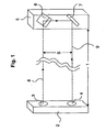
- Fig. 1 shows at one end of a protection area 1, in a common Housing 2, a light emitter 3 and a light receiver 4.
- a deflection unit 5 with a first Reflection element 6 and a second reflection element 7 shown.
- first Reflection element 6 Of a emanating from the light emitter transmit light beam is here only his optical Axis 8 shown, which radiates through the protection area 1 and at the end the first reflection element 6 impinges.
- the first reflection element 6 here as a roof edge mirror is shown, the transmitted light beam within the Deflection unit 5 is deflected by approximately 90 ° and then meets the second Reflection element 7, which has the shape of a plane mirror.
- the transmitted light beam shown here with his optical axis 9, again in the protection area 1 a.
- the two form Reflection elements 6 and 7 thus a triple mirror, which the incident Transmitted light bundle, parallel offset by a beam distance S, back into his The output direction reflected back.
- the two reflection elements 6 and 7 can also, comparable to an optical triple reflector, through a transparent Plastic or glass body can be realized.
- the evaluation circuit is in the position due to the incident on the light receiver optical radiation determine whether the light path from the light emitter 3, through the protection area 1, over the deflection unit 5 and again back through the protection area 1 for Light receiver 4 is free, or is interrupted by a possible object.
- the Evaluation circuit then provides an output signal, depending on the state of the light path, for controlling a warning signal, for switching off a rear the protected area machine or the like.
- both the light transmitter 3 and the light receiver 4 are shown in a common housing 2.
- the deflection unit 5 is arranged with its two reflection elements described in more detail in Fig. 1.
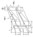
- the transmitting light lobe 10 emerging from the housing 2 at the light emitter 3 has an approximately rectangular beam profile which increases with increasing distance.
- the protection area 1 it has a height h s in the direction of the beam spacing S and a width b s in the axis orthogonal thereto.
- a light entrance window 11 is clearly outshined at the deflection unit 5.
- the housing 2 can now be rotated in its axis y in the positive or negative direction until the light entrance window 11 is just barely illuminated by the transmitting light lobe 10. These geometric relationships can also be transferred to a rotation of the housing 2 about an axis X.
- the particular arrangement of the two reflection elements to a triple mirror in the deflection unit 5 ensures that the light bundle component emerging from the light exit window 12 passes exactly to the light receiver 4.
- the light receiver 4 can detect this light beam component only when the light exit window 12 is located within the receiving light lobe 13.
- the two send and receive lobes do not overlap within the protection area 1 and thus an unwanted shortening of the protective field can occur in the case of a specular object within the overlap region, the condition h S ⁇ S and h E ⁇ S is mandatory to comply.
Landscapes
- Engineering & Computer Science (AREA)
- General Engineering & Computer Science (AREA)
- Mechanical Engineering (AREA)
- Physics & Mathematics (AREA)
- Life Sciences & Earth Sciences (AREA)
- General Life Sciences & Earth Sciences (AREA)
- General Physics & Mathematics (AREA)
- Geophysics (AREA)
- Burglar Alarm Systems (AREA)
- Optical Communication System (AREA)
- Photo Coupler, Interrupter, Optical-To-Optical Conversion Devices (AREA)
- Geophysics And Detection Of Objects (AREA)
- Materials For Photolithography (AREA)
- Light Receiving Elements (AREA)
- Photovoltaic Devices (AREA)
Description
Die optoelektronische Zugangsabsicherung erzeugt somit einen Schutzbereich, dessen Funktion vergleichbar mit einer Absperrleine ist. Im einfachsten Fall befinden sich dazu am Anfang und am Ende des Schutzbereiches ein Lichtsender, der ein Sendelichtbündel in den Schutzbereich aussendet, während am Ende des Schutzbereiches ein Lichtempfänger das ankommende Sendelichtbündel empfängt, in eine elektrische Größe umwandelt und einer Auswerteschaltung zuführt. Die Auswerteschaltung ist somit in der Lage zu erkennen, ob das Sendelichtbündel innerhalb des Schutzbereiches unterbrochen wurde oder nicht. Vergleichbar einer einzelnen Absperrleine kann auch ein einzelnes Sendelichtbündel im Schutzbereich überschritten werden. Um dies zu verhindern, werden deshalb meist zwei oder mehrere Sendelichtbündel mit einem endlichen Strahlabstand zueinander durch den Schutzbereich geführt. Bei diesen Lösungen, wo sich der bzw. die Lichtsender am Anfang des Schutzbereiches und der bzw. die Lichtempfänger am Ende des Schutzbereiches befinden, sind auf beiden Seiten des Schutzbereiches elektrische Installationen notwendig, die einen erhöhten Montageaufwand und damit verbunden zusätzliche Kosten verursachen. Deshalb gibt es Lösungen, bei denen sich der Lichtsender und der Lichtempfänger in einem gemeinsamen Gehäuse an einem Ende des Schutzbereiches befinden, während am anderen Ende des Schutzbereiches ein Retroreflektor angeordnet ist. So ist aus der DE 199 24 470 eine Reflexionslichtschranke bekannt, bei welcher der Lichtsender und der Lichtempfänger unmittelbar nebeneinander angeordnet sind und am Ende des Objektraumes ein Reflektor zur Lichtumkehr angebracht ist. Der "Strahlabstand" zwischen ausgesendetem und reflektiertem Lichtstrahl ist dabei jedoch sehr gering. Aus der EP 0 967 583 ist ebenfalls eine Lösung bekannt, bei der statt eines Retroreflektors eine spezielle Umlenkeinheit zum Einsatz kommt. Hierbei hat die Umlenkeinheit die Aufgabe, ein vom Lichtsender kommendes Sendelichtbündel zunächst um einen vorgegebenen Stahlabstand zu versetzen und schließlich wieder entlang des Schutzbereiches zum Lichtempfänger zu lenken. Auf diesem Wege ist es möglich, den Schutzbereich mit einem Lichtsender und einem Lichtempfänger mit zwei zueinander beabstandeten Sendelichtbündeln zu durchstrahlen, so dass die gezielte oder unbewusste Gefahr der Überbrückung einer einstrahligen optoelektronischen Zugangsabsicherung verhindert oder zumindest deutlich reduziert wird.
Für kurze Schutzbereiche, d. h. bis zu einem Abstand von ca. 1,5 m, ist nach der DE 195 33 044 eine zweistrahlige Lichtschranke bekannt, bei der ein erster paralleler Lichtstrahl nach exakter Reflexion an einem Tripelspiegel wieder als paralleler Lichtstrahl versetzt zurück reflektiert wird.
In der US 4,117,319 ist ein Justiersystem für Laser beschrieben, bei welchem zwischen zwei exakt justierbaren Spiegelelementen ein Laserstahl mehrfach reflektiert wird.
Dies ist besonders bei sehr kleinen Strahlabständen von Vorteil, weil die Sendelichtkeule und die Empfangslichtkeule so eingestellt werden können, dass sich diese innerhalb eines aktuellen Schutzbereiches gerade nicht überschneiden, wodurch einerseits eine sichere Funktion der optoelektronischen Zugangsabsicherung gewährleistet ist, andererseits die maximale Winkelverfügbarkeit für die Justage bzw. Montage zur Verfügung steht.
Es zeigen:
- Fig. 1
- eine schematische Ansicht einer optoelektronischen Zugangsabsicherung mit zwei Strahlen und einer Umlenkeinheit.
- Fig. 2
- eine perspektivische Ansicht einer Sendelichtkeule und einer Empfangslichtkeule der erfindungsgemäßen optoelektronischen Zugangsabsicherung.
Claims (4)
- Optoelektronische Zugangsabsicherung zur Überwachung eines Schutzbereiches (1) mit zumindest einem Lichtsender (3), einem Lichtempfänger (4), die in einem gemeinsamen Gehäuse (2) untergebracht sind und wenigstens einem ersten und einem zweiten Reflexionselement (6, 7), wobei ein Anteil der von dem Lichtsender (3) entlang des Schutzbereiches (1) ausgesandten Sendelichtkeule (10) auf das erste Reflexionselement (6) auftrifft, dabei zum zweiten Reflexionselement (7) gelenkt wird und anschließend um einen Strahlabstand (S) versetzt wieder entlang des Schutzbereiches (1) zu dem Lichtempfänger (4) umgelenkt wird, dadurch gekennzeichnet, dass die Sendelichtkeule (10) und die vom Lichtempfänger (4) aufgenommene Empfangslichtkeule (13) jeweils ein Strahlungsprofil aufweisen, dessen Ausdehnung in Richtung des Strahlabstandes (S) eine geringere Abmessung aufweist, als in der dazu rechtwinkligen Ausdehnung und dass sich die annähernd gleich dimensionierte Sendelichtkeule, bzw. die Empfangslichtkeule zweier benachbarter Lichtbündel, innerhalb des Schutzbereiches (1) nicht überlappen.
- Optoelektronische Zugangsabsicherung nach Anspruch 1, dadurch gekennzeichnet, dass die Ausdehnung der Sendelichtkeule bzw. der Empfangslichtkeule in der Längs- und Querachse einstellbar sind.
- Optoelektronische Zugangsabsicherung nach einem der vorhergehenden Ansprüche, dadurch gekennzeichnet, dass die Sendelichtkeule bzw. die Empfangslichtkeule annäherungsweise einen rechteckigen Querschnitt aufweisen.
- Optoelektronische Zugangsabsicherung nach einem der vorhergehenden Ansprüche, dadurch gekennzeichnet, dass die Sendelichtkeule bzw. die Empfangslichtkeule in Ihrer Längs- und Querausdehnung stufenlos getrennt einstellbar sind.
Applications Claiming Priority (2)
| Application Number | Priority Date | Filing Date | Title |
|---|---|---|---|
| DE10314852 | 2003-04-02 | ||
| DE10314852A DE10314852A1 (de) | 2003-04-02 | 2003-04-02 | Optoelektronische Zugangsabsicherung |
Publications (3)
| Publication Number | Publication Date |
|---|---|
| EP1467228A2 EP1467228A2 (de) | 2004-10-13 |
| EP1467228A3 EP1467228A3 (de) | 2004-10-20 |
| EP1467228B1 true EP1467228B1 (de) | 2005-10-19 |
Family
ID=32864351
Family Applications (1)
| Application Number | Title | Priority Date | Filing Date |
|---|---|---|---|
| EP04001882A Expired - Lifetime EP1467228B1 (de) | 2003-04-02 | 2004-01-29 | Optoelektronische Zugangsabsicherung |
Country Status (3)
| Country | Link |
|---|---|
| EP (1) | EP1467228B1 (de) |
| AT (1) | ATE307344T1 (de) |
| DE (2) | DE10314852A1 (de) |
Cited By (1)
| Publication number | Priority date | Publication date | Assignee | Title |
|---|---|---|---|---|
| EP4016139A1 (de) | 2020-12-21 | 2022-06-22 | Leuze electronic GmbH + Co. KG | Sensoranordnung |
Families Citing this family (7)
| Publication number | Priority date | Publication date | Assignee | Title |
|---|---|---|---|---|
| DE102004037859B4 (de) * | 2004-08-04 | 2007-05-16 | Siemens Ag | Medizinisches Gerät mit Einrichtung zur Kollisionvermeidung |
| EP1803989A1 (de) * | 2005-12-27 | 2007-07-04 | Datasensor S.p.A. | Sicherheits-Lichtschranke |
| ITMO20060219A1 (it) * | 2006-07-06 | 2008-01-07 | Datasensor Spa | Barriera di sicurezza |
| DE102006053359C5 (de) * | 2006-11-10 | 2015-12-10 | Sick Ag | Optoelektronische Sensoranordnung und Verfahren zum Justieren einer optoelektronischen Sensoranordnung |
| DE202008016946U1 (de) | 2008-12-20 | 2010-05-27 | Sick Ag | Lichtgitter oder Lichtschranke |
| DE102010044730A1 (de) * | 2010-09-08 | 2012-03-08 | Pantron Instruments Gmbh | Lichtschranke |
| DE102014202481A1 (de) * | 2014-02-12 | 2015-08-13 | Robert Bosch Gmbh | Linearbrandmelder sowie Verfahren zum Betreiben des Linearbrandmelders |
Family Cites Families (8)
| Publication number | Priority date | Publication date | Assignee | Title |
|---|---|---|---|---|
| US4117319A (en) * | 1977-07-05 | 1978-09-26 | Rockwell International Corporation | Alignment system for lasers |
| CH689336A5 (de) * | 1994-10-03 | 1999-02-26 | Baumer Electric Ag | Lichtschranke. |
| DE19537051C1 (de) * | 1995-10-05 | 1997-01-30 | Leuze Electronic Gmbh & Co | Optoelektronische Sensoranordnung |
| JP2944599B2 (ja) * | 1998-01-07 | 1999-09-06 | 株式会社ツーデン | 移動式ドアの安全装置並びに安全兼起動装置 |
| DE19828434A1 (de) * | 1998-06-25 | 1999-12-30 | Sick Ag | Optoelektronische Sensoreinrichtung |
| DE19924470A1 (de) * | 1999-05-28 | 2000-09-21 | Balluff Gebhard Feinmech | Reflexionslichtschranke und Verfahren zum Detektieren eines Objekts in einem Objektraum sowie Reflektoreinheit für eine solche Reflexionslichtschranke |
| DE19925553C2 (de) * | 1999-06-04 | 2003-10-16 | Leuze Lumiflex Gmbh & Co Kg | Optoelektrische Vorrichtung |
| DE19934870C1 (de) * | 1999-07-24 | 2001-01-18 | Leuze Electronic Gmbh & Co | Befestigungsvorrichtung |
-
2003
- 2003-04-02 DE DE10314852A patent/DE10314852A1/de not_active Withdrawn
-
2004
- 2004-01-29 DE DE502004000103T patent/DE502004000103D1/de not_active Expired - Lifetime
- 2004-01-29 EP EP04001882A patent/EP1467228B1/de not_active Expired - Lifetime
- 2004-01-29 AT AT04001882T patent/ATE307344T1/de not_active IP Right Cessation
Cited By (1)
| Publication number | Priority date | Publication date | Assignee | Title |
|---|---|---|---|---|
| EP4016139A1 (de) | 2020-12-21 | 2022-06-22 | Leuze electronic GmbH + Co. KG | Sensoranordnung |
Also Published As
| Publication number | Publication date |
|---|---|
| ATE307344T1 (de) | 2005-11-15 |
| DE10314852A1 (de) | 2004-10-14 |
| EP1467228A3 (de) | 2004-10-20 |
| DE502004000103D1 (de) | 2006-03-02 |
| EP1467228A2 (de) | 2004-10-13 |
Similar Documents
| Publication | Publication Date | Title |
|---|---|---|
| EP0889332A1 (de) | Lichtschranke oder Lichtvorhang mit Ausrichthilfe | |
| DE2851444A1 (de) | Lichtgitter | |
| DE10146639A1 (de) | Lichtgitter mit Strahlteiler | |
| EP1933172B1 (de) | Lichtschrankenanordnung | |
| EP1467228B1 (de) | Optoelektronische Zugangsabsicherung | |
| EP1408273A2 (de) | Schutzvorrichtung zur Überwachung eines mit einem Bauteil zu bewegenden Schutzbereichs | |
| WO2014086911A2 (de) | Optisches energieübertragungssystem | |
| EP1566588A1 (de) | Lichtschranke oder Lichtgitter mit Ausrichthilfe | |
| DE102004022408B4 (de) | Optischer Sensor | |
| EP1288559B1 (de) | Optoelektronische Überwachungseinrichtung | |
| DE10018284A1 (de) | Signalleuchte mit mindestens einem Leuchtmittel und einem Lichtleiter | |
| DE2518828C3 (de) | Lichtschranke | |
| DE202008016946U1 (de) | Lichtgitter oder Lichtschranke | |
| EP1780559B1 (de) | Optischer Sensor | |
| DE19537051C1 (de) | Optoelektronische Sensoranordnung | |
| DE20317617U1 (de) | Optoelektronische Sensoreinrichtung | |
| DE202005010358U1 (de) | Optoelektronisches Lichtgitter | |
| EP0967583B1 (de) | Optoelektronische Sensoreinrichtung | |
| DE10106155A1 (de) | Strahlformungsvorrichtung für die Formung des Querschnitts eines Lichtstrahls sowie Anordnung zur Einkopplung eines von einer langgestreckten Laserlichtquelle ausgehenden Lichtstrahls mit einem länglichen Querschnitt in eine Lichtleitfaser | |
| DE2811413A1 (de) | Naeherungsschalter | |
| EP1686398B1 (de) | Optoelektronischer Sensor | |
| EP1416457B1 (de) | Optische Überwachungsvorrichtung | |
| EP3454094A1 (de) | Optoelektronisches sensorsystem | |
| DE19639403A1 (de) | Optoelektronischer Sensor | |
| WO2018224365A1 (de) | Mikromechanische lichtumlenkvorrichtung |
Legal Events
| Date | Code | Title | Description |
|---|---|---|---|
| PUAI | Public reference made under article 153(3) epc to a published international application that has entered the european phase |
Free format text: ORIGINAL CODE: 0009012 |
|
| PUAL | Search report despatched |
Free format text: ORIGINAL CODE: 0009013 |
|
| AK | Designated contracting states |
Kind code of ref document: A2 Designated state(s): AT BE BG CH CY CZ DE DK EE ES FI FR GB GR HU IE IT LI LU MC NL PT RO SE SI SK TR |
|
| AX | Request for extension of the european patent |
Extension state: AL LT LV MK |
|
| AK | Designated contracting states |
Kind code of ref document: A3 Designated state(s): AT BE BG CH CY CZ DE DK EE ES FI FR GB GR HU IE IT LI LU MC NL PT RO SE SI SK TR |
|
| AX | Request for extension of the european patent |
Extension state: AL LT LV MK |
|
| 17P | Request for examination filed |
Effective date: 20050107 |
|
| 17Q | First examination report despatched |
Effective date: 20050303 |
|
| GRAP | Despatch of communication of intention to grant a patent |
Free format text: ORIGINAL CODE: EPIDOSNIGR1 |
|
| AKX | Designation fees paid |
Designated state(s): AT BE BG CH CY CZ DE DK EE ES FI FR GB GR HU IE IT LI LU MC NL PT RO SE SI SK TR |
|
| GRAS | Grant fee paid |
Free format text: ORIGINAL CODE: EPIDOSNIGR3 |
|
| GRAA | (expected) grant |
Free format text: ORIGINAL CODE: 0009210 |
|
| AK | Designated contracting states |
Kind code of ref document: B1 Designated state(s): AT BE BG CH CY CZ DE DK EE ES FI FR GB GR HU IE IT LI LU MC NL PT RO SE SI SK TR |
|
| PG25 | Lapsed in a contracting state [announced via postgrant information from national office to epo] |
Ref country code: CZ Free format text: LAPSE BECAUSE OF FAILURE TO SUBMIT A TRANSLATION OF THE DESCRIPTION OR TO PAY THE FEE WITHIN THE PRESCRIBED TIME-LIMIT Effective date: 20051019 Ref country code: NL Free format text: LAPSE BECAUSE OF FAILURE TO SUBMIT A TRANSLATION OF THE DESCRIPTION OR TO PAY THE FEE WITHIN THE PRESCRIBED TIME-LIMIT Effective date: 20051019 Ref country code: RO Free format text: LAPSE BECAUSE OF FAILURE TO SUBMIT A TRANSLATION OF THE DESCRIPTION OR TO PAY THE FEE WITHIN THE PRESCRIBED TIME-LIMIT Effective date: 20051019 Ref country code: FI Free format text: LAPSE BECAUSE OF FAILURE TO SUBMIT A TRANSLATION OF THE DESCRIPTION OR TO PAY THE FEE WITHIN THE PRESCRIBED TIME-LIMIT Effective date: 20051019 Ref country code: IE Free format text: LAPSE BECAUSE OF FAILURE TO SUBMIT A TRANSLATION OF THE DESCRIPTION OR TO PAY THE FEE WITHIN THE PRESCRIBED TIME-LIMIT Effective date: 20051019 Ref country code: SK Free format text: LAPSE BECAUSE OF FAILURE TO SUBMIT A TRANSLATION OF THE DESCRIPTION OR TO PAY THE FEE WITHIN THE PRESCRIBED TIME-LIMIT Effective date: 20051019 Ref country code: SI Free format text: LAPSE BECAUSE OF FAILURE TO SUBMIT A TRANSLATION OF THE DESCRIPTION OR TO PAY THE FEE WITHIN THE PRESCRIBED TIME-LIMIT Effective date: 20051019 |
|
| REG | Reference to a national code |
Ref country code: GB Ref legal event code: FG4D Free format text: NOT ENGLISH |
|
| REG | Reference to a national code |
Ref country code: CH Ref legal event code: EP |
|
| GBT | Gb: translation of ep patent filed (gb section 77(6)(a)/1977) | ||
| REG | Reference to a national code |
Ref country code: IE Ref legal event code: FG4D Free format text: LANGUAGE OF EP DOCUMENT: GERMAN |
|
| PG25 | Lapsed in a contracting state [announced via postgrant information from national office to epo] |
Ref country code: BG Free format text: LAPSE BECAUSE OF FAILURE TO SUBMIT A TRANSLATION OF THE DESCRIPTION OR TO PAY THE FEE WITHIN THE PRESCRIBED TIME-LIMIT Effective date: 20060119 Ref country code: GR Free format text: LAPSE BECAUSE OF FAILURE TO SUBMIT A TRANSLATION OF THE DESCRIPTION OR TO PAY THE FEE WITHIN THE PRESCRIBED TIME-LIMIT Effective date: 20060119 Ref country code: DK Free format text: LAPSE BECAUSE OF FAILURE TO SUBMIT A TRANSLATION OF THE DESCRIPTION OR TO PAY THE FEE WITHIN THE PRESCRIBED TIME-LIMIT Effective date: 20060119 Ref country code: SE Free format text: LAPSE BECAUSE OF FAILURE TO SUBMIT A TRANSLATION OF THE DESCRIPTION OR TO PAY THE FEE WITHIN THE PRESCRIBED TIME-LIMIT Effective date: 20060119 |
|
| PG25 | Lapsed in a contracting state [announced via postgrant information from national office to epo] |
Ref country code: AT Free format text: LAPSE BECAUSE OF NON-PAYMENT OF DUE FEES Effective date: 20060129 |
|
| PG25 | Lapsed in a contracting state [announced via postgrant information from national office to epo] |
Ref country code: ES Free format text: LAPSE BECAUSE OF FAILURE TO SUBMIT A TRANSLATION OF THE DESCRIPTION OR TO PAY THE FEE WITHIN THE PRESCRIBED TIME-LIMIT Effective date: 20060130 |
|
| PG25 | Lapsed in a contracting state [announced via postgrant information from national office to epo] |
Ref country code: BE Free format text: LAPSE BECAUSE OF NON-PAYMENT OF DUE FEES Effective date: 20060131 Ref country code: MC Free format text: LAPSE BECAUSE OF NON-PAYMENT OF DUE FEES Effective date: 20060131 Ref country code: LU Free format text: LAPSE BECAUSE OF NON-PAYMENT OF DUE FEES Effective date: 20060131 |
|
| REF | Corresponds to: |
Ref document number: 502004000103 Country of ref document: DE Date of ref document: 20060302 Kind code of ref document: P |
|
| PG25 | Lapsed in a contracting state [announced via postgrant information from national office to epo] |
Ref country code: PT Free format text: LAPSE BECAUSE OF FAILURE TO SUBMIT A TRANSLATION OF THE DESCRIPTION OR TO PAY THE FEE WITHIN THE PRESCRIBED TIME-LIMIT Effective date: 20060320 |
|
| NLV1 | Nl: lapsed or annulled due to failure to fulfill the requirements of art. 29p and 29m of the patents act | ||
| PG25 | Lapsed in a contracting state [announced via postgrant information from national office to epo] |
Ref country code: HU Free format text: LAPSE BECAUSE OF FAILURE TO SUBMIT A TRANSLATION OF THE DESCRIPTION OR TO PAY THE FEE WITHIN THE PRESCRIBED TIME-LIMIT Effective date: 20060420 |
|
| REG | Reference to a national code |
Ref country code: IE Ref legal event code: FD4D |
|
| ET | Fr: translation filed | ||
| PLBI | Opposition filed |
Free format text: ORIGINAL CODE: 0009260 |
|
| 26 | Opposition filed |
Opponent name: LEUZE LUMIFLEX GMBH + CO. KG Effective date: 20060713 |
|
| PLAX | Notice of opposition and request to file observation + time limit sent |
Free format text: ORIGINAL CODE: EPIDOSNOBS2 |
|
| PLBB | Reply of patent proprietor to notice(s) of opposition received |
Free format text: ORIGINAL CODE: EPIDOSNOBS3 |
|
| RAP2 | Party data changed (patent owner data changed or rights of a patent transferred) |
Owner name: SICK AG |
|
| BERE | Be: lapsed |
Owner name: SICK A.G. Effective date: 20060131 |
|
| PLCK | Communication despatched that opposition was rejected |
Free format text: ORIGINAL CODE: EPIDOSNREJ1 |
|
| APBP | Date of receipt of notice of appeal recorded |
Free format text: ORIGINAL CODE: EPIDOSNNOA2O |
|
| APAH | Appeal reference modified |
Free format text: ORIGINAL CODE: EPIDOSCREFNO |
|
| PG25 | Lapsed in a contracting state [announced via postgrant information from national office to epo] |
Ref country code: EE Free format text: LAPSE BECAUSE OF FAILURE TO SUBMIT A TRANSLATION OF THE DESCRIPTION OR TO PAY THE FEE WITHIN THE PRESCRIBED TIME-LIMIT Effective date: 20051019 |
|
| APBQ | Date of receipt of statement of grounds of appeal recorded |
Free format text: ORIGINAL CODE: EPIDOSNNOA3O |
|
| PG25 | Lapsed in a contracting state [announced via postgrant information from national office to epo] |
Ref country code: TR Free format text: LAPSE BECAUSE OF FAILURE TO SUBMIT A TRANSLATION OF THE DESCRIPTION OR TO PAY THE FEE WITHIN THE PRESCRIBED TIME-LIMIT Effective date: 20051019 |
|
| REG | Reference to a national code |
Ref country code: CH Ref legal event code: PL |
|
| PG25 | Lapsed in a contracting state [announced via postgrant information from national office to epo] |
Ref country code: CH Free format text: LAPSE BECAUSE OF NON-PAYMENT OF DUE FEES Effective date: 20080131 Ref country code: LI Free format text: LAPSE BECAUSE OF NON-PAYMENT OF DUE FEES Effective date: 20080131 |
|
| PG25 | Lapsed in a contracting state [announced via postgrant information from national office to epo] |
Ref country code: CY Free format text: LAPSE BECAUSE OF FAILURE TO SUBMIT A TRANSLATION OF THE DESCRIPTION OR TO PAY THE FEE WITHIN THE PRESCRIBED TIME-LIMIT Effective date: 20051019 |
|
| APBU | Appeal procedure closed |
Free format text: ORIGINAL CODE: EPIDOSNNOA9O |
|
| PLBN | Opposition rejected |
Free format text: ORIGINAL CODE: 0009273 |
|
| STAA | Information on the status of an ep patent application or granted ep patent |
Free format text: STATUS: OPPOSITION REJECTED |
|
| 27O | Opposition rejected |
Effective date: 20081220 |
|
| PGFP | Annual fee paid to national office [announced via postgrant information from national office to epo] |
Ref country code: GB Payment date: 20130122 Year of fee payment: 10 |
|
| GBPC | Gb: european patent ceased through non-payment of renewal fee |
Effective date: 20140129 |
|
| PG25 | Lapsed in a contracting state [announced via postgrant information from national office to epo] |
Ref country code: GB Free format text: LAPSE BECAUSE OF NON-PAYMENT OF DUE FEES Effective date: 20140129 |
|
| REG | Reference to a national code |
Ref country code: FR Ref legal event code: PLFP Year of fee payment: 12 |
|
| PGFP | Annual fee paid to national office [announced via postgrant information from national office to epo] |
Ref country code: IT Payment date: 20150126 Year of fee payment: 12 |
|
| PGFP | Annual fee paid to national office [announced via postgrant information from national office to epo] |
Ref country code: FR Payment date: 20150115 Year of fee payment: 12 |
|
| REG | Reference to a national code |
Ref country code: FR Ref legal event code: ST Effective date: 20160930 |
|
| PG25 | Lapsed in a contracting state [announced via postgrant information from national office to epo] |
Ref country code: FR Free format text: LAPSE BECAUSE OF NON-PAYMENT OF DUE FEES Effective date: 20160201 |
|
| PG25 | Lapsed in a contracting state [announced via postgrant information from national office to epo] |
Ref country code: IT Free format text: LAPSE BECAUSE OF NON-PAYMENT OF DUE FEES Effective date: 20160129 |
|
| PGFP | Annual fee paid to national office [announced via postgrant information from national office to epo] |
Ref country code: DE Payment date: 20180124 Year of fee payment: 15 |
|
| REG | Reference to a national code |
Ref country code: DE Ref legal event code: R119 Ref document number: 502004000103 Country of ref document: DE |
|
| PG25 | Lapsed in a contracting state [announced via postgrant information from national office to epo] |
Ref country code: DE Free format text: LAPSE BECAUSE OF NON-PAYMENT OF DUE FEES Effective date: 20190801 |