EP1467220A2 - Passive shimming of an MRI magnet - Google Patents
Passive shimming of an MRI magnet Download PDFInfo
- Publication number
- EP1467220A2 EP1467220A2 EP04251880A EP04251880A EP1467220A2 EP 1467220 A2 EP1467220 A2 EP 1467220A2 EP 04251880 A EP04251880 A EP 04251880A EP 04251880 A EP04251880 A EP 04251880A EP 1467220 A2 EP1467220 A2 EP 1467220A2
- Authority
- EP
- European Patent Office
- Prior art keywords
- yoke
- magnetic field
- blocks
- magnet
- shimming
- Prior art date
- Legal status (The legal status is an assumption and is not a legal conclusion. Google has not performed a legal analysis and makes no representation as to the accuracy of the status listed.)
- Ceased
Links
- 238000000034 method Methods 0.000 description 19
- XEEYBQQBJWHFJM-UHFFFAOYSA-N Iron Chemical compound [Fe] XEEYBQQBJWHFJM-UHFFFAOYSA-N 0.000 description 7
- 238000003384 imaging method Methods 0.000 description 7
- 239000000463 material Substances 0.000 description 7
- 230000006870 function Effects 0.000 description 5
- 238000004519 manufacturing process Methods 0.000 description 5
- 238000005481 NMR spectroscopy Methods 0.000 description 3
- 238000013459 approach Methods 0.000 description 3
- 238000004590 computer program Methods 0.000 description 3
- 238000010586 diagram Methods 0.000 description 3
- 229910052742 iron Inorganic materials 0.000 description 3
- 238000005259 measurement Methods 0.000 description 3
- 239000000126 substance Substances 0.000 description 3
- 239000013598 vector Substances 0.000 description 3
- 230000005284 excitation Effects 0.000 description 2
- 238000010438 heat treatment Methods 0.000 description 2
- 238000012423 maintenance Methods 0.000 description 2
- 230000001105 regulatory effect Effects 0.000 description 2
- 238000007792 addition Methods 0.000 description 1
- 238000010276 construction Methods 0.000 description 1
- 230000001186 cumulative effect Effects 0.000 description 1
- 238000013461 design Methods 0.000 description 1
- 238000011143 downstream manufacturing Methods 0.000 description 1
- 230000000694 effects Effects 0.000 description 1
- 230000007717 exclusion Effects 0.000 description 1
- 230000004807 localization Effects 0.000 description 1
- 239000000696 magnetic material Substances 0.000 description 1
- 230000005415 magnetization Effects 0.000 description 1
- 239000011159 matrix material Substances 0.000 description 1
- 230000007246 mechanism Effects 0.000 description 1
- 229910001172 neodymium magnet Inorganic materials 0.000 description 1
- 238000007493 shaping process Methods 0.000 description 1
Images

Classifications
-
- G—PHYSICS
- G01—MEASURING; TESTING
- G01R—MEASURING ELECTRIC VARIABLES; MEASURING MAGNETIC VARIABLES
- G01R33/00—Arrangements or instruments for measuring magnetic variables
- G01R33/20—Arrangements or instruments for measuring magnetic variables involving magnetic resonance
- G01R33/28—Details of apparatus provided for in groups G01R33/44 - G01R33/64
- G01R33/38—Systems for generation, homogenisation or stabilisation of the main or gradient magnetic field
- G01R33/387—Compensation of inhomogeneities
- G01R33/3873—Compensation of inhomogeneities using ferromagnetic bodies ; Passive shimming
Definitions
- the magnets used in such an apparatus are often formulated from a plurality of magnetized blocks.
- the magnetized blocks are then arranged on a yoke plate so that each of the magnet blocks has a same magnetic pole facing upward. A pole piece is then placed on the top of the magnetized blocks.
- magnetic field gradients Gx Gy and Gz
- the region to be imaged is scanned by a sequence of measurement cycles in which these gradients vary according to the particular localization method being used.
- the resulting set of received NMR signals are digitized and processed to reconstruct the image using one of many well known reconstruction techniques.
- MRI magnets typically require not only an intensive uniform magnetic field, typically less than 10 ppm within a 40-50cm spherical volume, but also an accurate center magnetic field value, typically less than 0.5%.
- an intensive uniform magnetic field typically less than 10 ppm within a 40-50cm spherical volume
- an accurate center magnetic field value typically less than 0.5%.
- the bandwidth is fixed.
- the allowable range of the center magnetic field is also fixed.
- One known configuration of the magnetic field generating device for MRI is the open geometry composed of yokes opposite to each other, connected by post(s), magnetic field generating elements, such as permanent magnets and/or superconducting/resistive coils, and other field shaping components, such as pole pieces.
- a method for altering a magnetic field includes measuring a center magnetic field of an MRI system to obtain a center magnetic field value and using a B0 controlled shimming to change the center magnetic field to a value different the measured value.
- Figure 1 is a block schematic diagram of an imaging system 10 such as an MRI system 10 including two plate yokes 12 and a plurality of columnar yokes 14 extending between plate yokes 12.
- an MRI system 10 with a single C shaped yoke 16 may be used as shown in Figure 2.
- System 10 includes magnet blocks 18 secured to yoke surfaces, pole piece bases 20 and support rings 22 secured to magnets 18 and a pole piece 24 is secured to each pole piece base 20 and support ring 22.
- a gap 25 is formed between pole pieces 24.
- a body part to be imaged is inserted into gap 25.
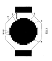
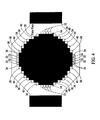
- shimming of a magnet assembly such as central assembly 30 may be achieved without requiring mechanical variations to the magnet assembly after the magnet assembly has been assembled.
- the method which may be carried out as a set of instructions of a computer program by one or more computers, analyzes the center magnetic field. A comparison is then made to the desired center magnet field strength, and active and/or passive shim elements may then be incorporated into the magnet assembly at different places to achieve the desired center magnetic field strength. The shimming or weighting factors are used to determine the amount of "shimming material" that is used at each place.
- One technique begins with the reception of system and shim constraints input. From the system and shim constraints, an objective function is formulated.
- the objective function which may take one of many forms, is defined to determine a minimum amount of shimming required throughout the magnet assembly such that the desired center field strength is achieved or, if applicable during a field maintenance procedure, is maintained.
- the shimming algorithm may utilize one of a number of objective functions designed to address field inhomogeneities and field strength simultaneously.
- a Linear Programming (LP) approach or implementation may be used or a least squares method.
- central assembly 30 is disposed on yoke 12 and the center magnetic field is measured.
- the center magnetic field is measured such as with a Tesla meter or Gauss meter.
- the measured value is compared against a desired value and a set of blocks is disposed on yoke 12 at a periphery of central assembly 30.
- different MRI systems have substantially the same center magnetic field strength but with different configurations of magnetic blocks to account for manufacturing differences between various blocks 18.
- a single MRI can have different block configurations for a top yoke 50 and a bottom yoke 52 (Shown in Figure 1) to adjust the center magnetic field.
- the herein described methods and apparatus provide a novel approach to changing the center magnetic field.
- the herein described methods and apparatus also provide methods and apparatus useable during an assembly of an MRI system and after assembly.
Landscapes
- Physics & Mathematics (AREA)
- Condensed Matter Physics & Semiconductors (AREA)
- General Physics & Mathematics (AREA)
- Magnetic Resonance Imaging Apparatus (AREA)
Abstract
Description
Claims (4)
- A product line of MRI systems, said product line comprising:a first MRI system (10) comprising:a first set of magnet blocks (32, 34, 36, 38, 40) mounted to said second yoke at a periphery of said second central assembly.a first yoke (12); anda plurality of magnet blocks (18) forming a first central assembly (30) disposed on said first yoke; anda second MRI system (10) comprising:a second yoke (12);a plurality of magnet blocks (18) forming a second central assembly (30) disposed on said second yoke and shaped the same as said first central assembly; and
- A product line in accordance with Claim 1 wherein said first MRI system (10) further comprises:a second set of magnet blocks (32, 34, 36, 38, 40) mounted to said first yoke (12) at a periphery of said first central assembly (30), said second set in a different configuration than said first set.
- A product line in accordance with Claim 1 wherein said first set of magnet blocks (32, 34, 36, 38, 40) comprises a set of half blocks (32, 34).
- A product line in accordance with Claim 3 wherein said second MRI system (10) further comprises a second set of half blocks (32, 34) disposed on said second yoke (12) adjacent said first set.
Applications Claiming Priority (2)
| Application Number | Priority Date | Filing Date | Title |
|---|---|---|---|
| US407887 | 2003-04-04 | ||
| US10/407,887 US6844801B2 (en) | 2003-03-21 | 2003-04-04 | Methods and apparatus for adjusting center magnetic field of a magnetic field generator for MRI |
Publications (2)
| Publication Number | Publication Date |
|---|---|
| EP1467220A2 true EP1467220A2 (en) | 2004-10-13 |
| EP1467220A3 EP1467220A3 (en) | 2005-10-26 |
Family
ID=32869178
Family Applications (1)
| Application Number | Title | Priority Date | Filing Date |
|---|---|---|---|
| EP04251880A Ceased EP1467220A3 (en) | 2003-04-04 | 2004-03-30 | Passive shimming of an MRI magnet |
Country Status (4)
| Country | Link |
|---|---|
| US (1) | US6844801B2 (en) |
| EP (1) | EP1467220A3 (en) |
| JP (1) | JP4783556B2 (en) |
| CN (1) | CN100536769C (en) |
Families Citing this family (6)
| Publication number | Priority date | Publication date | Assignee | Title |
|---|---|---|---|---|
| JP4743117B2 (en) * | 2004-07-01 | 2011-08-10 | 日立金属株式会社 | Magnetic field generator |
| US20070285197A1 (en) * | 2006-06-08 | 2007-12-13 | General Electric Company | Method for disassembling a magnetic field generator |
| AU2008325088A1 (en) * | 2007-11-06 | 2009-05-14 | T2 Biosystems, Inc. | Small magnet and RF coil for magnetic resonance relaxometry |
| CN104459584B (en) * | 2009-12-02 | 2018-03-20 | 纳纳利塞斯公司 | Method and apparatus for producing uniform magnetic field |
| CN106556813B (en) * | 2016-11-25 | 2021-09-24 | 上海辰光医疗科技股份有限公司 | Linear mixed optimization method of active shimming coil in magnetic resonance system |
| JP6929667B2 (en) * | 2017-03-10 | 2021-09-01 | キヤノンメディカルシステムズ株式会社 | Magnetic resonance imaging device and static magnetic field correction method |
Family Cites Families (18)
| Publication number | Priority date | Publication date | Assignee | Title |
|---|---|---|---|---|
| JPS60189905A (en) * | 1984-03-09 | 1985-09-27 | Mitsubishi Electric Corp | High uniformity magnetic-field generator |
| JPH01283905A (en) * | 1988-05-11 | 1989-11-15 | Hitachi Medical Corp | Method for deviating uniform magnetic field for mri apparatus and magnetostatic field generating apparatus using the method |
| JPH03131234A (en) * | 1989-07-07 | 1991-06-04 | Sumitomo Special Metals Co Ltd | Equipment for generating magnetic field for mri |
| JPH0394732A (en) * | 1989-09-08 | 1991-04-19 | Sumitomo Special Metals Co Ltd | Magnetic field generator for mri |
| JPH05152120A (en) * | 1991-11-29 | 1993-06-18 | Shin Etsu Chem Co Ltd | Magnetic-field generation apparatus and adjusting method for magnetic-field uniformity |
| US5668516A (en) | 1995-12-29 | 1997-09-16 | General Electric Company | Simplified active shield superconducting magnet assembly for magnetic resonance imaging |
| JP3705861B2 (en) * | 1996-03-21 | 2005-10-12 | 株式会社日立メディコ | Superconducting magnet device and method for adjusting magnetization thereof |
| JP2953659B1 (en) * | 1998-08-06 | 1999-09-27 | 住友特殊金属株式会社 | Magnetic field generator for MRI, method of assembling the same, and method of assembling magnet unit used therein |
| US6358582B1 (en) | 1998-11-19 | 2002-03-19 | General Electric Company | Laminated composite shell assembly for magnet applications |
| US5999076A (en) | 1998-12-30 | 1999-12-07 | General Electric Company | Magnetic resonance imaging passively shimmed superconducting magnet assembly |
| KR100319923B1 (en) * | 1999-05-10 | 2002-01-09 | 윤종용 | Apparatus for generating a magnetic field in an Magnetic Resonance Imaging |
| JP4123649B2 (en) * | 1999-08-12 | 2008-07-23 | 日立金属株式会社 | Magnetic field generator and method of assembling the same |
| US6252405B1 (en) | 1999-11-15 | 2001-06-26 | General Electric Company | Temperature compensated NMR magnet and method of operation therefor |
| EP1102077B1 (en) * | 1999-11-16 | 2006-03-08 | Neomax Co., Ltd. | Pole-piece unit for an MRI magnet |
| JP3559262B2 (en) * | 2000-10-06 | 2004-08-25 | 株式会社Neomax | Magnetic field adjustment device, magnetic field adjustment method, and recording medium |
| JP4338166B2 (en) * | 2001-03-13 | 2009-10-07 | 信越化学工業株式会社 | Magnetic field generator for MRI |
| US6504461B2 (en) | 2001-03-26 | 2003-01-07 | General Electric Company | Open magnet with recessed field shaping coils |
| JP2003024296A (en) * | 2001-07-04 | 2003-01-28 | Ge Medical Systems Global Technology Co Llc | Static magnetic field adjusting method and mri equipment |
-
2003
- 2003-04-04 US US10/407,887 patent/US6844801B2/en not_active Expired - Fee Related
-
2004
- 2004-03-30 EP EP04251880A patent/EP1467220A3/en not_active Ceased
- 2004-04-01 CN CNB2004100321494A patent/CN100536769C/en not_active Expired - Fee Related
- 2004-04-02 JP JP2004109822A patent/JP4783556B2/en not_active Expired - Fee Related
Also Published As
| Publication number | Publication date |
|---|---|
| JP4783556B2 (en) | 2011-09-28 |
| CN100536769C (en) | 2009-09-09 |
| US6844801B2 (en) | 2005-01-18 |
| EP1467220A3 (en) | 2005-10-26 |
| CN1535654A (en) | 2004-10-13 |
| US20040196126A1 (en) | 2004-10-07 |
| JP2004305744A (en) | 2004-11-04 |
Similar Documents
| Publication | Publication Date | Title |
|---|---|---|
| Han et al. | Integrated parallel reception, excitation, and shimming (iPRES) | |
| US6294972B1 (en) | Method for shimming a static magnetic field in a local MRI coil | |
| US5332971A (en) | Permanent magnet for nuclear magnetic resonance imaging equipment | |
| CN103069296B (en) | Method and apparatus for compensating B1 inhomogeneity in magnetic resonance imaging by non-selective tailored RF pulses | |
| US5614827A (en) | Method and apparatus for shimming a magnet system of a nuclear magnetic resonance tomography system | |
| EP1460445B1 (en) | Method of magnetic field controlled shimming | |
| US20040066194A1 (en) | Magnetic field generating assembly and method | |
| US8614575B2 (en) | NMR, MRI, and spectroscopic MRI in inhomogeneous fields | |
| US10261148B2 (en) | Magnetic resonance imaging apparatus and manufacturing method thereof | |
| JP6308794B2 (en) | MR apparatus having a pulsed compensation gradient magnetic field | |
| JPH0779942A (en) | Magnetic resonance imaging equipment | |
| AU2019396124B2 (en) | Gradient coil system | |
| US6844801B2 (en) | Methods and apparatus for adjusting center magnetic field of a magnetic field generator for MRI | |
| Hillenbrand et al. | High-order MR shimming: a simulation study of the effectiveness of competing methods, using an established susceptibility model of the human head | |
| US6744252B2 (en) | Magnetic field correcting method, magnetic field generating apparatus, and magnetic resonance imaging apparatus | |
| US7135948B2 (en) | Dipole shim coil for external field adjustment of a shielded superconducting magnet | |
| US10267877B2 (en) | Magnetic field homogeneity adjustment method, magnetic field homogeneity adjustment program and magnetic field homogeneity adjustment device | |
| IL105664A (en) | Asymmetric radio frequency coil for magnetic resonance imaging | |
| CN111615637B (en) | Method for performing diffusion-weighted magnetic resonance measurements | |
| US7570141B2 (en) | Method of designing a shim coil to reduce field settling time | |
| US6351125B1 (en) | Method of homogenizing magnetic fields | |
| JP2011152348A (en) | Magnetic resonance imaging apparatus | |
| JP3705995B2 (en) | Gradient coil manufacturing method, gradient coil, and magnetic resonance imaging apparatus | |
| US10641851B2 (en) | Radio frequency coil-array for magnetic resonance examination system | |
| US20060158291A1 (en) | Magnetic field generating device and method of shimming thereof |
Legal Events
| Date | Code | Title | Description |
|---|---|---|---|
| PUAI | Public reference made under article 153(3) epc to a published international application that has entered the european phase |
Free format text: ORIGINAL CODE: 0009012 |
|
| AK | Designated contracting states |
Kind code of ref document: A2 Designated state(s): AT BE BG CH CY CZ DE DK EE ES FI FR GB GR HU IE IT LI LU MC NL PL PT RO SE SI SK TR |
|
| AX | Request for extension of the european patent |
Extension state: AL LT LV MK |
|
| PUAL | Search report despatched |
Free format text: ORIGINAL CODE: 0009013 |
|
| AK | Designated contracting states |
Kind code of ref document: A3 Designated state(s): AT BE BG CH CY CZ DE DK EE ES FI FR GB GR HU IE IT LI LU MC NL PL PT RO SE SI SK TR |
|
| AX | Request for extension of the european patent |
Extension state: AL LT LV MK |
|
| RIC1 | Information provided on ipc code assigned before grant |
Ipc: 7G 01R 33/383 B Ipc: 7G 01R 33/3873 A |
|
| 17P | Request for examination filed |
Effective date: 20060426 |
|
| AKX | Designation fees paid |
Designated state(s): GB IT |
|
| REG | Reference to a national code |
Ref country code: DE Ref legal event code: 8566 |
|
| 17Q | First examination report despatched |
Effective date: 20060810 |
|
| APBN | Date of receipt of notice of appeal recorded |
Free format text: ORIGINAL CODE: EPIDOSNNOA2E |
|
| APAF | Appeal reference modified |
Free format text: ORIGINAL CODE: EPIDOSCREFNE |
|
| APBT | Appeal procedure closed |
Free format text: ORIGINAL CODE: EPIDOSNNOA9E |
|
| APAM | Information on closure of appeal procedure modified |
Free format text: ORIGINAL CODE: EPIDOSCNOA9E |
|
| STAA | Information on the status of an ep patent application or granted ep patent |
Free format text: STATUS: THE APPLICATION HAS BEEN REFUSED |
|
| 18R | Application refused |
Effective date: 20090607 |