EP1467155B1 - Solar system - Google Patents
Solar system Download PDFInfo
- Publication number
- EP1467155B1 EP1467155B1 EP04450079A EP04450079A EP1467155B1 EP 1467155 B1 EP1467155 B1 EP 1467155B1 EP 04450079 A EP04450079 A EP 04450079A EP 04450079 A EP04450079 A EP 04450079A EP 1467155 B1 EP1467155 B1 EP 1467155B1
- Authority
- EP
- European Patent Office
- Prior art keywords
- primary
- heat exchanger
- circuit
- wat
- primary circuit
- Prior art date
- Legal status (The legal status is an assumption and is not a legal conclusion. Google has not performed a legal analysis and makes no representation as to the accuracy of the status listed.)
- Expired - Lifetime
Links
- 239000007788 liquid Substances 0.000 claims description 13
- 230000004913 activation Effects 0.000 claims description 2
- XLYOFNOQVPJJNP-UHFFFAOYSA-N water Substances O XLYOFNOQVPJJNP-UHFFFAOYSA-N 0.000 description 12
- 239000000203 mixture Substances 0.000 description 5
- 239000012530 fluid Substances 0.000 description 4
- 230000004087 circulation Effects 0.000 description 3
- 230000005855 radiation Effects 0.000 description 3
- LYCAIKOWRPUZTN-UHFFFAOYSA-N Ethylene glycol Chemical compound OCCO LYCAIKOWRPUZTN-UHFFFAOYSA-N 0.000 description 2
- 230000002528 anti-freeze Effects 0.000 description 2
- 230000001419 dependent effect Effects 0.000 description 2
- 230000008014 freezing Effects 0.000 description 2
- 238000007710 freezing Methods 0.000 description 2
- 230000035515 penetration Effects 0.000 description 2
- 230000002349 favourable effect Effects 0.000 description 1
- 230000006870 function Effects 0.000 description 1
- 238000005338 heat storage Methods 0.000 description 1
- 238000010438 heat treatment Methods 0.000 description 1
- WGCNASOHLSPBMP-UHFFFAOYSA-N hydroxyacetaldehyde Natural products OCC=O WGCNASOHLSPBMP-UHFFFAOYSA-N 0.000 description 1
- -1 if it is very cold Substances 0.000 description 1
- GBMDVOWEEQVZKZ-UHFFFAOYSA-N methanol;hydrate Chemical compound O.OC GBMDVOWEEQVZKZ-UHFFFAOYSA-N 0.000 description 1
- 238000000034 method Methods 0.000 description 1
- 239000013526 supercooled liquid Substances 0.000 description 1
- 239000008399 tap water Substances 0.000 description 1
- 235000020679 tap water Nutrition 0.000 description 1
Images
Classifications
-
- F—MECHANICAL ENGINEERING; LIGHTING; HEATING; WEAPONS; BLASTING
- F24—HEATING; RANGES; VENTILATING
- F24D—DOMESTIC- OR SPACE-HEATING SYSTEMS, e.g. CENTRAL HEATING SYSTEMS; DOMESTIC HOT-WATER SUPPLY SYSTEMS; ELEMENTS OR COMPONENTS THEREFOR
- F24D19/00—Details
- F24D19/0095—Devices for preventing damage by freezing
-
- F—MECHANICAL ENGINEERING; LIGHTING; HEATING; WEAPONS; BLASTING
- F24—HEATING; RANGES; VENTILATING
- F24D—DOMESTIC- OR SPACE-HEATING SYSTEMS, e.g. CENTRAL HEATING SYSTEMS; DOMESTIC HOT-WATER SUPPLY SYSTEMS; ELEMENTS OR COMPONENTS THEREFOR
- F24D19/00—Details
- F24D19/10—Arrangement or mounting of control or safety devices
- F24D19/1006—Arrangement or mounting of control or safety devices for water heating systems
- F24D19/1009—Arrangement or mounting of control or safety devices for water heating systems for central heating
- F24D19/1042—Arrangement or mounting of control or safety devices for water heating systems for central heating the system uses solar energy
-
- F—MECHANICAL ENGINEERING; LIGHTING; HEATING; WEAPONS; BLASTING
- F24—HEATING; RANGES; VENTILATING
- F24S—SOLAR HEAT COLLECTORS; SOLAR HEAT SYSTEMS
- F24S40/00—Safety or protection arrangements of solar heat collectors; Preventing malfunction of solar heat collectors
- F24S40/70—Preventing freezing
-
- F—MECHANICAL ENGINEERING; LIGHTING; HEATING; WEAPONS; BLASTING
- F24—HEATING; RANGES; VENTILATING
- F24D—DOMESTIC- OR SPACE-HEATING SYSTEMS, e.g. CENTRAL HEATING SYSTEMS; DOMESTIC HOT-WATER SUPPLY SYSTEMS; ELEMENTS OR COMPONENTS THEREFOR
- F24D11/00—Central heating systems using heat accumulated in storage masses
-
- Y—GENERAL TAGGING OF NEW TECHNOLOGICAL DEVELOPMENTS; GENERAL TAGGING OF CROSS-SECTIONAL TECHNOLOGIES SPANNING OVER SEVERAL SECTIONS OF THE IPC; TECHNICAL SUBJECTS COVERED BY FORMER USPC CROSS-REFERENCE ART COLLECTIONS [XRACs] AND DIGESTS
- Y02—TECHNOLOGIES OR APPLICATIONS FOR MITIGATION OR ADAPTATION AGAINST CLIMATE CHANGE
- Y02B—CLIMATE CHANGE MITIGATION TECHNOLOGIES RELATED TO BUILDINGS, e.g. HOUSING, HOUSE APPLIANCES OR RELATED END-USER APPLICATIONS
- Y02B10/00—Integration of renewable energy sources in buildings
- Y02B10/20—Solar thermal
-
- Y—GENERAL TAGGING OF NEW TECHNOLOGICAL DEVELOPMENTS; GENERAL TAGGING OF CROSS-SECTIONAL TECHNOLOGIES SPANNING OVER SEVERAL SECTIONS OF THE IPC; TECHNICAL SUBJECTS COVERED BY FORMER USPC CROSS-REFERENCE ART COLLECTIONS [XRACs] AND DIGESTS
- Y02—TECHNOLOGIES OR APPLICATIONS FOR MITIGATION OR ADAPTATION AGAINST CLIMATE CHANGE
- Y02B—CLIMATE CHANGE MITIGATION TECHNOLOGIES RELATED TO BUILDINGS, e.g. HOUSING, HOUSE APPLIANCES OR RELATED END-USER APPLICATIONS
- Y02B10/00—Integration of renewable energy sources in buildings
- Y02B10/70—Hybrid systems, e.g. uninterruptible or back-up power supplies integrating renewable energies
-
- Y—GENERAL TAGGING OF NEW TECHNOLOGICAL DEVELOPMENTS; GENERAL TAGGING OF CROSS-SECTIONAL TECHNOLOGIES SPANNING OVER SEVERAL SECTIONS OF THE IPC; TECHNICAL SUBJECTS COVERED BY FORMER USPC CROSS-REFERENCE ART COLLECTIONS [XRACs] AND DIGESTS
- Y02—TECHNOLOGIES OR APPLICATIONS FOR MITIGATION OR ADAPTATION AGAINST CLIMATE CHANGE
- Y02E—REDUCTION OF GREENHOUSE GAS [GHG] EMISSIONS, RELATED TO ENERGY GENERATION, TRANSMISSION OR DISTRIBUTION
- Y02E10/00—Energy generation through renewable energy sources
- Y02E10/40—Solar thermal energy, e.g. solar towers
Definitions
- the invention relates to a solar system with a solar collector, which is connected via a primary fluid circuit to the primary side of a heat exchanger, with a memory which is connected via a secondary fluid circuit to the secondary side of the heat exchanger, with a primary pump in the primary circuit and a secondary pump in the secondary circuit and with a controller for controlling the pumps as a function of temperatures measured by sensors, wherein at least the primary circuit can be activated as soon as measured temperatures or their differences are above or below predeterminable values.
- a solar system is eg from document US 5,413,091 known.
- the fully closed primary circuit which contains one or more solar panels, usually filled with water, the antifreeze, z.
- glycol is added to such an extent that freezing and thus damage to pipes, but especially of the solar collector, can be excluded.
- the secondary circuit the thermally via a heat exchanger, z. B. a plate exchanger, is connected to the primary circuit, but usually contains normal tap water, which should optionally also be available as service water, and therefore no antifreeze can be added.
- the liquid cools in the primary circuit, at least in the region of the unprotected most of the weather solar panel of the respective outside temperature according to low temperatures, eg. B.-15 ° C, from.
- the cold liquid conveyed via the pump in the primary circuit, reaches the heat exchanger, which is usually located in a building and therefore protected against frost.
- the now flowing through the heat exchanger primary fluid if it is very cold, lead to a freezing of the water from the secondary circuit. This can lead to serious damage, especially to the heat exchanger. Such damage is particularly unpleasant because they naturally occur in winter, ie at a time when a failure of the solar system is particularly unpleasant. Until the faulty heat exchanger is repaired, further frost (damage) damage may occur.
- the controller is adapted to maintain after a request to activate the primary circuit by means of a hydraulic means initially a heat exchanger at least substantially exclusive Hilfssprimärniklauf up to one by means of a Sensor in the area of the primary circuit measured temperature exceeds a frost damage excluding value.
- the mentioned frost damage in particular the heat exchanger, can be avoided in a simple and effective manner.
- a favorable and effective embodiment is characterized in that the hydraulic means is a valve assembly in the primary circuit, with which the primary side of the heat exchanger can be bridged.
- valve assembly is a three-way valve, by means of which the primary side of the heat exchanger can be bridged via a bypass. It is useful in this case, when the three-way valve sits in the return of the primary circuit and is connected to the bypass. A further improvement, especially at very low outside temperatures, is obtained if a check valve is arranged in the inlet of the primary circuit on the side of the heat exchanger.
- valve assembly consists of two three-way valves on the two sides of the bypass, which are controlled by the controller at bridging the primary side of the heat exchanger completely separate this primary side of the collector-containing part of the primary circuit.
- valve assembly consists of a four-way valve, which controlled by the controller, when bypassing the primary side of the heat exchanger, this primary side completely separated from the sun collector containing part of the primary circuit.
- a primary auxiliary pump is provided which, after activation by the controller near a collector, a primary, the heat exchanger exclusive auxiliary circuit can maintain until a minimum temperature in Collector area is reached.
- a check valve is arranged in the primary circuit between the auxiliary pump and the heat exchanger.
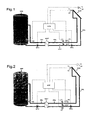
- the schematically illustrated solar system has a solar collector SOK, which is connected via a primary fluid circuit PKL to the primary side of a heat exchanger WAT.
- a primary pump PPU conveys a liquid, usually a water-methanol mixture in this closed primary circuit between the solar collector SOK and the primary side of the heat exchanger WAT.
- the latter may be formed, for example, as a plate exchanger.
- the solar collector SOK can consist of several units connected in parallel and / or in series.
- the secondary circuit SKL is connected on the one hand to the secondary side of the heat exchanger WAT and on the other hand to a water reservoir SPE, wherein a secondary pump SPU provides for the promotion of the water in the secondary circuit SKL.
- a secondary pump SPU provides for the promotion of the water in the secondary circuit SKL.
- the liquid circulating in the primary circuit PKL is constantly heated and releases its heat to the secondary circuit SKL via the heat exchanger WAT, heat storage being carried out in the reservoir SPE, i. H. the water in this memory SPE heats up.
- the water from the reservoir SPE or in the secondary circuit SKL can be used in a manner not shown here for heating purposes and / or as process water in a household or business.
- the corresponding connection fittings etc. are, as not essential to the invention, not shown here.
- a controller STE which switches on the system depending on various temperatures measured by sensors and quite generally controls various valves and pumps, which adjusts the operation of the system to the existing or desired temperatures.
- the control generated here is explained only insofar as it is related to the invention. In fact, the controller can have other tasks, especially in connection with the heat and water supply on the secondary side.
- the temperature T1 in the region of the solar collector SOK is measured with the aid of a sensor S1, and the corresponding measured value is fed to the controller STE.
- This sensor S2 can, for example, measure the temperature of the water present in the reservoir SPE at a selected location.
- a temperature sensor S3 the temperature T3 in the primary circuit is measured remotely from the solar collector SOK.
- a sun sensor S4 may be provided, which has a temperature T4 or one of the irradiation power, measured z. B. in W / m 2 , corresponding value.
- a three-way valve is inserted in the manner shown, which is also connected via a bypass BYP to the inlet of the heat exchanger WAT to the solar collector SOK.
- a check valve RSV is inserted between the bypass BYP and the heat exchanger WAT in the inlet.
- the controlled by the controller STE three-way valve V1 can be controlled so that it either completely free the return, so that caused by the pump PPU circulation between the solar collector SOK and the primary side of the heat exchanger WAT can go undisturbed.
- the valve can be controlled so that the primary side of the heat exchanger WAT is excluded by the bypass BYP from this cycle.
- the controller is now configured to start the primary pump PPU when the temperature T1 at the collector-side sensor S1 exceeds a temperature T2 measured with the memory-side sensor S2 by an adjustable magnitude.
- the start can additionally be made dependent on the fact that a predeterminable minimum temperature T1 at the sensor S1 has been reached. Now the water is pumped by the pump PPU in the primary circuit PKL.
- Another predefinable start condition is that the temperature or radiation value T4 detected by the sun sensor S4 exceeds a certain value and, moreover, the temperature T2 exceeds the temperature T1 by a certain amount.
- the temperature or radiation value T4 exceeds a specific value and, in addition, the temperature T1 in the collector region has a minimum value.
- the invention now uses here that when switching on the primary pump PPU the liquid does not flow through the primary side of the heat exchanger WAT, but by the correspondingly switched valve V1 via the bypass BYP on the heat exchanger WAT over again in the direction of solar collector SOK.
- the controller only switches over the valve V1 when the primary pump PPU has already been in operation for some time and until the temperature T3 measured with the sensor S3 has reached a value which excludes frost damage.
- the temperature T3 should, for example, not have minus degrees.
- the said time delay is necessary so that in the primary circuit PKL a reasonably stationary temperature state is reached.
- the temperatures may be very different when the solar collector SOK is outdoors and covered, for example, with ice or snow, whereas in general the three-way valve V1 and the primary pump PPU are in a more protected area, e.g. B. are arranged in a building.
- the temperature T3 it is additionally or alternatively possible to set the condition that the temperature T1 in the collector region has a certain minimum value
- the invention it is ensured that no cold liquid of the collector connection lines or snow covered collectors flows in the direction of the heat exchanger WAT and also a mistakenly manually switched primary pump PPU, the cold water-glycol mixture is no longer in the direction of insufficient sunlight Transport heat exchanger WAT and destroying the heat exchanger WAT is avoided.
- Destroying the heat exchanger by frost can not only destroy the heat exchanger WAT as such, but it could mix the pure water of the secondary circuit SKL with the water-glycol mixture of the primary circuit PKL, which ultimately freeze the piping of the primary circuit and the solar panels SOK and could be destroyed.
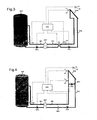
- Fig. 2 In the execution after Fig. 2 is another three-way valve V2 is provided and that at the other end of the bypass BYP in the lead of the primary circuit PKL.
- the three-way valve V1 off Fig. 1 is here designated by the reference symbol V1 '.
- Both three-way valves V1 'and V2 are controlled by the controller STE so that in the initial state after switching on the system, the primary pump PPU drives the liquid exclusively via the bypass BYP past the primary side of the heat exchanger WAT.
- the check valve RSV the Fig. 1 omitted. Incidentally, this embodiment is completely the same as that after Fig.1 ,
- Fig. 3 shows that instead of a three-way valve VI or two three-way valves V1 ', V2, a four-way valve V3 can be provided. Also, this valve V3 is controlled by the controller STE so that in the already described initial operating state, in which the liquid in the primary circuit PKL is still so cold that damage to the Heat exchanger WAT is to be feared, the liquid is pumped directly through the four-way valve V3 using the primary pump PPU, past the primary side of the heat exchanger WAT.
- the controller STE switches the four-way valve V3, so that the normal operating state is reached at which the liquid flows in the primary circuit PKL from the solar collector SOK directly to the primary side of the heat exchanger WAT and from here through the Pump PPU driven back to the solar collector SOK.
- the execution is the same as in the case of the Fig. 1 and 2 ,
- FIG. 4 A variant that uses no controllable valves in Fig. 4 shown.
- an additional pump namely an auxiliary pump HPU arranged at the solar collector SOK or in the vicinity in a bypass.
- auxiliary pump HPU When this auxiliary pump HPU is in operation, a cycle new solar collector SOK can be maintained.
- the temperature T3 is measured in this circuit, slightly away from the solar collector SOK, whereas the temperature T1 is measured in the immediate area of the solar collector SOK or at this.
- the control STE is thus set up to turn on the system according to the above-mentioned or other temperature-dependent starting conditions, for. B. turn on the auxiliary pump HPU when the temperature T1 at the collector near sensor S1, the measured temperature S2 with the memory SPE at the memory SPE exceeds by an adjustable size and when a minimum temperature T1 has been reached at the sensor S1. It is then the liquid in the primary circuit PKL pumped only in the described small circuit near the solar collector SOK.
- a check valve RSV as in FIG Fig. 4 shown to be prevented.
- an additional shut-off valve it is also possible to install an additional shut-off valve.
- the controller also has a differential control for the secondary circuit SKL, comparing the temperatures T3 and T2. As soon as the temperature T3 at the sensor S3 exceeds the temperature T2 which is measured at the memory SPE with the sensor S2 by an adjustable magnitude and a predetermined minimum temperature T3 at the sensor S3 is reached, the secondary pump SPU and the actual primary pump PPU switched on and the auxiliary pump HPU in the bypass BPA is turned off.
Landscapes
- Engineering & Computer Science (AREA)
- General Engineering & Computer Science (AREA)
- Thermal Sciences (AREA)
- Chemical & Material Sciences (AREA)
- Combustion & Propulsion (AREA)
- Mechanical Engineering (AREA)
- Physics & Mathematics (AREA)
- Life Sciences & Earth Sciences (AREA)
- Sustainable Development (AREA)
- Sustainable Energy (AREA)
- Air Conditioning Control Device (AREA)
- Other Air-Conditioning Systems (AREA)
- Control Of Temperature (AREA)
Description
Die Erfindung bezieht sich auf eine Solaranlage mit einem Sonnenkollektor , der über einen Primär-Flüssigkeitskreislauf an die Primärseite eines Wärmetauschers angeschlossen ist, mit einem Speicher, der über einen Sekundär-Flüssigkeitskreislauf an die Sekundärseite des Wärmetauschers angeschlossen ist, mit einer Primärpumpe in dem Primärkreislauf und einer Sekundärpumpe in dem Sekundärkreislauf sowie mit einer Steuerung zur Ansteuerung der Pumpen in Abhängigkeit von mittels Sensoren gemessenen Temperaturen, wobei zumindest der Primärkreislauf aktivierbar ist, sobald gemessene Temperaturen oder deren Differenzen vorgebbare Werte über- oder unterschreiten. Eine solche Solaranlage ist z.B. aus Dokument
Bei derartigen Anlagen ist der völlig geschlossene Primärkreislauf, welcher einen oder mehrere Sonnenkollektoren enthält, üblicherweise mit Wasser gefüllt, dem ein Frostschutzmittel, z. B. Glykol, in einem solchen Ausmaß beigemengt ist, dass ein Einfrieren und damit eine Beschädigung von Leitungen, vor allem aber des Sonnenkollektors, ausgeschlossen werden kann.In such systems, the fully closed primary circuit, which contains one or more solar panels, usually filled with water, the antifreeze, z. As glycol, is added to such an extent that freezing and thus damage to pipes, but especially of the solar collector, can be excluded.
Der Sekundärkreislauf, der thermisch über einen Wärmetauscher, z. B. einen Plattentauscher, mit dem Primärkreislauf in Verbindung steht, enthält jedoch üblicherweise normales Leitungswasser, das gegebenenfalls auch als Brauchwasser zur Verfügung stehen soll, und dem daher kein Frostschutzmittel beigemengt werden kann.The secondary circuit, the thermally via a heat exchanger, z. B. a plate exchanger, is connected to the primary circuit, but usually contains normal tap water, which should optionally also be available as service water, and therefore no antifreeze can be added.
Wenn die Anlage, z. B. bei Nacht, nicht in Betrieb ist und Winterbedingungen herrschen, kühlt sich die Flüssigkeit im Primärkreislauf, jedenfalls im Bereich des meist vor Witterung ungeschützten Sonnenkollektors der jeweiligen Außentemperatur entsprechend auf tiefe Temperaturen, z. B.-15° C, ab.If the plant, z. B. at night, is not in operation and prevail winter conditions, the liquid cools in the primary circuit, at least in the region of the unprotected most of the weather solar panel of the respective outside temperature according to low temperatures, eg. B.-15 ° C, from.
So bald die Anlage eingeschaltet wird, gelangt die kalte Flüssigkeit, gefördert über die Pumpe im Primärkreislauf, zu dem Wärmetauscher, welcher sich üblicherweise in einem Gebäude befindet und daher frostgeschützt ist. Die nun den Wärmetauscher durchströmende Primärflüssigkeit kann, wenn sie sehr kalt ist, zu einem Gefrieren des Wassers aus dem Sekundärkreislauf führen. Dadurch kann es zu schweren Schäden, insbesondere an dem Wärmetauscher kommen. Derartige Schäden sind besonders unangenehm, da sie naturgemäß im Winter auftreten, d. h. zu einer Zeit, zu der ein Ausfall der Solaranlage besonders unangenehm ist. Bis der defekte Wärmetauscher repariert ist, können weitere Frost(folge)-schäden auftreten.As soon as the system is switched on, the cold liquid, conveyed via the pump in the primary circuit, reaches the heat exchanger, which is usually located in a building and therefore protected against frost. The now flowing through the heat exchanger primary fluid, if it is very cold, lead to a freezing of the water from the secondary circuit. This can lead to serious damage, especially to the heat exchanger. Such damage is particularly unpleasant because they naturally occur in winter, ie at a time when a failure of the solar system is particularly unpleasant. Until the faulty heat exchanger is repaired, further frost (damage) damage may occur.
Es ist eine Aufgabe der Erfindung, eine Solaranlage zu schaffen, welche frei von den oben genannten Nachteilen ist.It is an object of the invention to provide a solar system which is free of the above-mentioned disadvantages.
Diese Aufgabe wird mit einer Solaranlage der eingangs genannten Art gelöst, bei welcher erfindungsgemäß die Steuerung dazu eingerichtet ist, nach einer Aufforderung zum Aktivieren des Primärkreislaufs mit Hilfe eines hydraulischen Mittels vorerst einen den Wärmetauscher zumindest im wesentlichen ausschließenden Hilfsprimärkreislauf aufrecht zu erhalten, bis eine mittels eines Sensors im Bereich des Primärkreislaufs gemessene Temperatur einen Frostschäden ausschließenden Wert übersteigt.This object is achieved with a solar system of the type mentioned, in which according to the invention the controller is adapted to maintain after a request to activate the primary circuit by means of a hydraulic means initially a heat exchanger at least substantially exclusive Hilfssprimärkreislauf up to one by means of a Sensor in the area of the primary circuit measured temperature exceeds a frost damage excluding value.
Dank der Erfindung können die erwähnten Frostschäden, insbesondere der Wärmetauscher, auf einfache und wirkungsvolle Weise vermieden werden.Thanks to the invention, the mentioned frost damage, in particular the heat exchanger, can be avoided in a simple and effective manner.
Eine günstige und wirksame Ausführungsform zeichnet sich dadurch aus, dass das hydraulische Mittel eine Ventilanordnung im Primärkreislauf ist, mit welcher die Primärseite des Wärmetauschers überbrückbar ist.A favorable and effective embodiment is characterized in that the hydraulic means is a valve assembly in the primary circuit, with which the primary side of the heat exchanger can be bridged.
Dabei kann als sehr einfache Variante vorgesehen sein, dass die Ventilanordnung ein Dreiwegeventil ist, mit dessen Hilfe die Primärseite des Wärmetauschers über einen Bypass überbrückbar ist. Zweckdienlich ist es in diesem Fall, wenn das Dreiwegeventil im Rücklauf des Primärkreislaufs sitzt und mit dem Bypass verbunden ist. Eine weitere Verbesserung besonders bei sehr niederen Außentemperaturen ergibt sich, falls im Zulauf des Primärkreislaufs an der Seite des Wärmetauschers ein Rückschlagventil angeordnet ist.It can be provided as a very simple variant that the valve assembly is a three-way valve, by means of which the primary side of the heat exchanger can be bridged via a bypass. It is useful in this case, when the three-way valve sits in the return of the primary circuit and is connected to the bypass. A further improvement, especially at very low outside temperatures, is obtained if a check valve is arranged in the inlet of the primary circuit on the side of the heat exchanger.
Als besonders sichere Alternative bietet sich an, dass die Ventilanordnung aus zwei Dreiwegeventilen an den beiden Seiten des Bypass besteht, welche von der Steuerung gesteuert bei Überbrückung der Primärseite des Wärmetauschers diese Primärseite vollständig von dem den Kollektor enthaltenden Teil des Primärkreislaufs abtrennen.A particularly safe alternative is that the valve assembly consists of two three-way valves on the two sides of the bypass, which are controlled by the controller at bridging the primary side of the heat exchanger completely separate this primary side of the collector-containing part of the primary circuit.
Gleichfalls durch besondere Sicherheit zeichnet sich eine Ausführung aus, bei welcher die Ventilanordnung aus einem Vier-Wege-Ventil besteht, welches von der Steuerung gesteuert, bei Überbrückung der Primärseite des Wärmetauschers diese Primärseite vollständig von dem den Sonnenkollektor enthaltenden Teil des Primärkreislaufs abtrennt.Likewise, by special security, an embodiment is characterized in which the valve assembly consists of a four-way valve, which controlled by the controller, when bypassing the primary side of the heat exchanger, this primary side completely separated from the sun collector containing part of the primary circuit.
Bei einer Variante, welche keine gesteuerten Ventile verwendet, ist vorgesehen, dass zusätzlich zu der Primärkreispumpe eine primäre Hilfspumpe vorgesehen ist, welche nach Aktivierung durch die Steuerung kollektornahe einen primären, den Wärmetauscher ausschließenden Hilfskreislauf aufrecht erhalten kann, bis eine Mindesttemperatur im Kollektorbereich erreicht ist. Hierbei kann es, je nach verwendeter Hilfspumpe, zweckmäßig sein, wenn im Primärkreislauf zwischen Hilfspumpe und Wärmetauscher ein Rückschlagventil angeordnet ist.In a variant which does not use controlled valves, it is provided that in addition to the primary circuit pump, a primary auxiliary pump is provided which, after activation by the controller near a collector, a primary, the heat exchanger exclusive auxiliary circuit can maintain until a minimum temperature in Collector area is reached. Depending on the auxiliary pump used, it may be expedient if a check valve is arranged in the primary circuit between the auxiliary pump and the heat exchanger.
Unter Bezugnahme auf
Der Sekundärkreislauf SKL ist einerseits an die Sekundärseite des Wärmetauschers WAT und andererseits an einen Wasserspeicher SPE angeschlossen, wobei eine Sekundärpumpe SPU für die Förderung des Wassers im Sekundärkreislauf SKL sorgt. Wenn im Betrieb Sonnen- oder Wärmestrahlung auf den Sonnenkollektor SOK einfällt, wird die im Primärkreislauf PKL zirkulierende Flüssigkeit ständig erwärmt und gibt Ihre Wärme über den Wärmetauscher WAT an den Sekundärkreislauf SKL ab, wobei eine Wärmespeicherung in dem Speicher SPE erfolgt, d. h. das Wasser in diesem Speicher SPE heizt sich auf. Je nach Konzeption der Solaranlage kann das Wasser aus dem Speicher SPE bzw. in dem Sekundärkreislauf SKL in hier nicht gezeigter Weise für Heizzwecke verwendet werden und/oder als Brauchwasser in einem Haushalt oder Betrieb. Die entsprechenden Anschlussarmaturen etc. sind, da für die Erfindung unwesentlich, hier nicht dargestellt.The secondary circuit SKL is connected on the one hand to the secondary side of the heat exchanger WAT and on the other hand to a water reservoir SPE, wherein a secondary pump SPU provides for the promotion of the water in the secondary circuit SKL. In operation, when solar or thermal radiation is incident on the solar collector SOK, the liquid circulating in the primary circuit PKL is constantly heated and releases its heat to the secondary circuit SKL via the heat exchanger WAT, heat storage being carried out in the reservoir SPE, i. H. the water in this memory SPE heats up. Depending on the design of the solar system, the water from the reservoir SPE or in the secondary circuit SKL can be used in a manner not shown here for heating purposes and / or as process water in a household or business. The corresponding connection fittings etc. are, as not essential to the invention, not shown here.
Wie bei jeder derzeitigen Solaranlage ist auch hier eine Steuerung STE vorgesehen, die in Abhängigkeit vor allem verschiedener durch Sensoren gemessener Temperaturen die Anlage einschaltet und ganz allgemein verschiedene Ventile und Pumpen steuert, welche den Betrieb der Anlage den vorhandenen bzw. gewünschten Temperaturen anpasst. Die hier gezeugte Steuerung wird nur insoweit erläutert, als sie in Zusammenhang mit der Erfindung steht. Tatsächlich können der Steuerung noch weitere Aufgaben, vor allem in Zusammenhang mit der Wärme- und Wasserversorgung an der Sekundärseite zukommen.As with any current solar system, a controller STE is also provided here, which switches on the system depending on various temperatures measured by sensors and quite generally controls various valves and pumps, which adjusts the operation of the system to the existing or desired temperatures. The control generated here is explained only insofar as it is related to the invention. In fact, the controller can have other tasks, especially in connection with the heat and water supply on the secondary side.
Im vorliegenden Beispiel wird mit Hilfe eines Sensors S1 die Temperatur T1 im Bereich des Sonnenkollektors SOK gemessen und der entsprechende Messwert der Steuerung STE zugeführt. Gleiches gilt für die im Speicherbereich gemessene Temperatur T2, für welche ein Temperatursensor S2 vorgesehen ist. Dieser Sensor S2 kann beispielsweise die Temperatur des im Speicher SPE vorhandenen Wassers an einer ausgewählten Stelle messen. Mit Hilfe eines Temperatursensors S3 wird die Temperatur T3 im Primärkreislauf entfernt von dem Sonnenkollektor SOK gemessen.In the present example, the temperature T1 in the region of the solar collector SOK is measured with the aid of a sensor S1, and the corresponding measured value is fed to the controller STE. The same applies to the temperature T2 measured in the storage area, for which a temperature sensor S2 is provided. This sensor S2 can, for example, measure the temperature of the water present in the reservoir SPE at a selected location. With help a temperature sensor S3, the temperature T3 in the primary circuit is measured remotely from the solar collector SOK.
Schließlich kann auch ein Sonnenfühler S4 vorgesehen sein, welcher eine Temperatur T4 oder einen der Einstrahlungsleistung, gemessen z. B. in W/m2, entsprechenden Wert misst.Finally, a sun sensor S4 may be provided, which has a temperature T4 or one of the irradiation power, measured z. B. in W / m 2 , corresponding value.
In den Rücklauf des Primärkreislaufs PKL ist ein Dreiwegeventil in der gezeigten Weise eingefügt, welches außerdem über einen Bypass BYP mit dem Zulauf von dem Wärmetauscher WAT zu dem Sonnenkollektor SOK verbunden ist. Außerdem ist noch zwischen dem Bypass BYP und dem Wärmetauscher WAT im Zulauf ein Rückschlagventil RSV eingefügt. Das von der Steuerung STE angesteuerte Dreiwegeventil V1 kann so gesteuert werden, dass es entweder den Rücklauf völlig freigibt, sodass die durch die Pumpe PPU verursache Zirkulation zwischen Sonnenkollektor SOK und Primärseite des Wärmetauschers WAT ungestört vor sich gehen kann. Andererseits kann das Ventil so angesteuert werden, dass die Primärseite des Wärmetauschers WAT durch den Bypass BYP aus diesem Kreislauf ausgeschlossen ist.In the return of the primary circuit PKL, a three-way valve is inserted in the manner shown, which is also connected via a bypass BYP to the inlet of the heat exchanger WAT to the solar collector SOK. In addition, a check valve RSV is inserted between the bypass BYP and the heat exchanger WAT in the inlet. The controlled by the controller STE three-way valve V1 can be controlled so that it either completely free the return, so that caused by the pump PPU circulation between the solar collector SOK and the primary side of the heat exchanger WAT can go undisturbed. On the other hand, the valve can be controlled so that the primary side of the heat exchanger WAT is excluded by the bypass BYP from this cycle.
Die Steuerung ist nun dazu eingerichtet, die Primärpumpe PPU zu starten, wenn die Temperatur T1 an dem kollektorseitigen Sensor S1 eine mit dem speicherseitigen Sensor S2 gemessene Temperatur T2 um eine einstellbare Größe überschreitet. Der Start kann zusätzlich davon abhängig gemacht werden, dass eine vorgebbare Mindesttemperatur T1 am Sensor S1 erreicht wurde. Nun wird das Wasser von der Pumpe PPU im Primärkreislauf PKL gepumpt.The controller is now configured to start the primary pump PPU when the temperature T1 at the collector-side sensor S1 exceeds a temperature T2 measured with the memory-side sensor S2 by an adjustable magnitude. The start can additionally be made dependent on the fact that a predeterminable minimum temperature T1 at the sensor S1 has been reached. Now the water is pumped by the pump PPU in the primary circuit PKL.
Eine andere vorgebbare Startbedingung ist die, dass der mit dem Sonnenfühler S4 erfasste Temperatur- oder Strahlungswert T4 einen bestimmten Wert überschreitet und außerdem die Temperatur T2 die Temperatur T1 um einen gewissen Betrag übersteigt.Another predefinable start condition is that the temperature or radiation value T4 detected by the sun sensor S4 exceeds a certain value and, moreover, the temperature T2 exceeds the temperature T1 by a certain amount.
Schließlich kann man als Startbedingung auch vorgeben, dass der Temperatur- oder Strahlungswert T4 einen bestimmten Wert übersteigt und zusätzlich die Temperatur T1 im Kollektorbereich einen Mindestwert aufweist.Finally, as a starting condition, it can also be specified that the temperature or radiation value T4 exceeds a specific value and, in addition, the temperature T1 in the collector region has a minimum value.
Die Erfindung setzt nun hier ein, dass beim Einschalten der Primärpumpe PPU die Flüssigkeit nicht über die Primärseite des Wärmetauschers WAT fließt, sondern durch das entsprechend geschaltete Ventil V1 über den Bypass BYP an dem Wärmetauscher WAT vorbei wieder in Richtung Sonnenkollektor SOK. Die Steuerung schaltet das Ventil V1 erst dann um, wenn die Primärpumpe PPU bereits einige Zeit in Betrieb war und bis die mit dem Sensor S3 gemessene Temperatur T3 einen Wert erreicht hat, der Frostschäden ausschließt.The invention now uses here that when switching on the primary pump PPU the liquid does not flow through the primary side of the heat exchanger WAT, but by the correspondingly switched valve V1 via the bypass BYP on the heat exchanger WAT over again in the direction of solar collector SOK. The controller only switches over the valve V1 when the primary pump PPU has already been in operation for some time and until the temperature T3 measured with the sensor S3 has reached a value which excludes frost damage.
Mit anderen Worten, soll die Temperatur T3 beispielsweise nicht mehr Minusgrade aufweisen. Die genannte Zeitverzögerung ist notwendig, damit in dem Primärkreislauf PKL ein halbwegs stationärer Temperaturzustand erreicht ist. Zu Beginn einer Inbetriebnahme können nämlich die Temperaturen sehr unterschiedlich sein, wenn sich der Sonnenkollektor SOK im Freien befindet und beispielsweise mit Eis oder Schnee bedeckt ist, wogegen im allgemeinen das Dreiwegeventil V1 und die Primärpumpe PPU in einem geschützteren Bereich, z. B. in einem Gebäude angeordnet sind. An Stelle der Temperatur T3 kann man zusätzlich oder alternativ auch die Bedingung stellen, dass die Temperatur T1 im Kollektorbereich einen bestimmten Mindestwert aufweistIn other words, the temperature T3 should, for example, not have minus degrees. The said time delay is necessary so that in the primary circuit PKL a reasonably stationary temperature state is reached. Namely, at the start of commissioning, the temperatures may be very different when the solar collector SOK is outdoors and covered, for example, with ice or snow, whereas in general the three-way valve V1 and the primary pump PPU are in a more protected area, e.g. B. are arranged in a building. In place of the temperature T3, it is additionally or alternatively possible to set the condition that the temperature T1 in the collector region has a certain minimum value
Um ein langsames Eindringen des kalten Wasser-Glykol-Gemischs in den Hinlauf des Primärkreislaufs PKL zu verhindern, kann zwischen den Wärmetauscher WAT und dem Bypass BYP in der in
Dank der Erfindung ist sicher gestellt, dass keine kalte Flüssigkeit der Kollektoranschlussleitungen oder der mit Schnee bedeckten Kollektoren in Richtung des Wärmetauschers WAT fließt und auch eine irrtümlich von Hand eingeschaltete Primärpumpe PPU kann das bei zu geringer Sonneneinstrahlung kalte Wasser-Glykol-Gemisch nicht mehr in Richtung Wärmetauscher WAT transportieren und ein Zerstören des Wärmetauschers WAT wird vermieden. Ein Zerstören des Wärmetauschers durch Frost kann nicht nur den Wärmetauscher WAT als solchen zerstören, sondern es könnte sich das reine Wasser des Sekundärkreislaufs SKL mit dem Wasser-Glykol-Gemisch des Primärkreislaufs PKL vermischen, wodurch letztlich die Verrohrung des Primärkreislaufs und die Sonnenkollektoren SOK einfrieren und zerstört werden könnten.Thanks to the invention it is ensured that no cold liquid of the collector connection lines or snow covered collectors flows in the direction of the heat exchanger WAT and also a mistakenly manually switched primary pump PPU, the cold water-glycol mixture is no longer in the direction of insufficient sunlight Transport heat exchanger WAT and destroying the heat exchanger WAT is avoided. Destroying the heat exchanger by frost can not only destroy the heat exchanger WAT as such, but it could mix the pure water of the secondary circuit SKL with the water-glycol mixture of the primary circuit PKL, which ultimately freeze the piping of the primary circuit and the solar panels SOK and could be destroyed.
Bei der Ausführung nach
Eine Variante, die keine steuerbaren Ventile verwendet ist in
Die Steuerung STE ist somit dazu eingerichtet, die Anlage entsprechend den oben angegebenen oder anderen temperaturabhängigen Startbedingungen einzuschalten, z. B. die Hilfspumpe HPU dann einzuschalten, wenn die Temperatur T1 an dem kollektornahen Sensor S1, die mit dem Sensor S2 gemessene Temperatur T2 bei dem Speicher SPE um eine einstellbare Größe überschreitet und wenn eine Mindesttemperatur T1 an dem Sensor S1 erreicht wurde. Es wird sodann die Flüssigkeit im Primärkreislauf PKL lediglich in dem Beschriebenen kleinen Kreislauf nahe des Sonnenkollektors SOK gepumpt. Um in diesem Zustand schleichende Zirkulationen in der Rohrleitung in Richtung des Wärmetauschers WAT zu vermeiden, ist auf einen entsprechenden Abstand zu achten, bzw. kann eine solche schleichende Zirkulation durch den Einbau beispielsweise eines Rückschlagventils RSV, wie in
Die Steuerung besitzt auch eine Differenzregelung für den Sekundärkreislauf SKL, wobei die Temperaturen T3 und T2 verglichen werden. Sobald die Temperatur T3 an dem Sensor S3 die Temperatur T2, welche bei dem Speicher SPE mit dem Sensor S2 gemessen wird, um eine einstellbare Größe überschreitet und eine vorgegebene Mindesttemperatur T3 an dem Sensor S3 erreicht ist, werden die Sekundärpumpe SPU und die eigentliche Primärpumpe PPU eingeschaltet und die Hilfspumpe HPU in dem Bypass BPA wird abgeschaltet.The controller also has a differential control for the secondary circuit SKL, comparing the temperatures T3 and T2. As soon as the temperature T3 at the sensor S3 exceeds the temperature T2 which is measured at the memory SPE with the sensor S2 by an adjustable magnitude and a predetermined minimum temperature T3 at the sensor S3 is reached, the secondary pump SPU and the actual primary pump PPU switched on and the auxiliary pump HPU in the bypass BPA is turned off.
Auch auf diese Weise wird das angestrebte Ziel, nämlich Eindringen von unterkühlter Flüssigkeit in den Primärkreis PKL zu dem Wärmetauscher WAT vermieden.In this way, the desired goal, namely penetration of supercooled liquid in the primary circuit PKL is avoided to the heat exchanger WAT.
Claims (9)
- Solar system comprising a solar collector (SOK) which is connected to the primary side of a heat exchanger (WAT) via a primary liquid circuit (PKL), comprising a storage tank (SPE) which is connected to the secondary side of the heat exchanger via a secondary liquid circuit (SKL), comprising a primary pump (PPU) in the primary circuit and a secondary pump (SPU) in the secondary circuit, and comprising a controller (STE) for controlling the pumps (PPU, SPU) as a function of temperatures (T1 and T4, respectively) measured by means of sensors (S1, S2, S3, S4), wherein at least the primary circuit can be activated as soon as measured temperatures (T4) or their differences exceed or fall below predefinable values,
characterised in that
the controller (STE) is configured such that following a request to activate the primary circuit it initially maintains an auxiliary primary circuit which at least substantially excludes the heat exchanger (WAT) with the aid of a hydraulic means (V1, V1' + V2, HPU, V3) until a temperature (T3, T1) measured by means of a sensor (S3, S1) in the region of the primary circuit and/or the collector (SOK) exceeds a value that rules out frost damage. - Solar system according to claim 1, characterised in that the hydraulic means is a valve arrangement (V1, V1' + V2, V3) in the primary circuit by means of which the primary side of the heat exchanger (WAT) can be bypassed.
- Solar system according to claim 2, characterised in that the valve arrangement is a three-way valve (V1) with the aid of which the primary side of the heat exchanger can be bypassed by way of a bypass (BYP).
- Solar system according to claim 3, characterised in that the three-way valve (V1) sits in the return line of the primary circuit and is connected to the bypass (BYP).
- Solar system according to one of claims 2 to 4, characterised in that a non-return valve (RSV) is arranged in the inflow of the primary circuit on the side of the heat exchanger (WAT).
- Solar system according to claim 2, characterised in that the valve arrangement consists of two three-way valves (V1', V2) on the two sides of the bypass (BYP) which, under the control of the controller (STE), when the primary side of the heat exchanger (WAT) is bypassed, completely isolate said primary side from the part of the primary circuit containing the collector (SOK).
- Solar system according to claim 2, characterised in that the valve arrangement consists of a four-way valve (V3) which, under the control of the controller (STE), when the primary side of the heat exchanger (WAT) is bypassed, completely isolates said primary side from the part of the primary circuit (PKL) containing the collector (SOK).
- Solar system according to claim 1, characterised in that in addition to the primary circuit pump (PPU) there is provided a primary auxiliary pump (HPU) which, following activation by the controller (STE), can maintain close to the collector a primary auxiliary circuit excluding the heat exchanger (WAT) until a minimum temperature (T1) has been reached in the collector region.
- Solar system according to claim 8, characterised in that a non-return valve (RSV) is arranged in the primary circuit (PKL) between auxiliary pump (HPU) and heat exchanger (WAT).
Applications Claiming Priority (2)
| Application Number | Priority Date | Filing Date | Title |
|---|---|---|---|
| AT0055403A AT412505B (en) | 2003-04-09 | 2003-04-09 | SOLAR SYSTEM |
| AT5542003 | 2003-04-09 |
Publications (3)
| Publication Number | Publication Date |
|---|---|
| EP1467155A2 EP1467155A2 (en) | 2004-10-13 |
| EP1467155A3 EP1467155A3 (en) | 2004-12-15 |
| EP1467155B1 true EP1467155B1 (en) | 2009-09-30 |
Family
ID=32831418
Family Applications (1)
| Application Number | Title | Priority Date | Filing Date |
|---|---|---|---|
| EP04450079A Expired - Lifetime EP1467155B1 (en) | 2003-04-09 | 2004-04-01 | Solar system |
Country Status (3)
| Country | Link |
|---|---|
| EP (1) | EP1467155B1 (en) |
| AT (2) | AT412505B (en) |
| DE (1) | DE502004010143D1 (en) |
Families Citing this family (4)
| Publication number | Priority date | Publication date | Assignee | Title |
|---|---|---|---|---|
| DE102008029527A1 (en) * | 2007-06-29 | 2009-01-02 | Vaillant Gmbh | Solar thermal system and method for operating such a system |
| CN108266781A (en) * | 2018-02-07 | 2018-07-10 | 北京民利储能技术有限公司 | A kind of fused salt heating installation |
| CN111306609A (en) * | 2020-02-27 | 2020-06-19 | 中国第一汽车股份有限公司 | Building time-sharing control heating temperature energy-saving system |
| CN112050282B (en) * | 2020-09-09 | 2024-05-24 | 大连理工大学 | Intelligent sensing heat recovery solar heating roof system |
Family Cites Families (3)
| Publication number | Priority date | Publication date | Assignee | Title |
|---|---|---|---|---|
| DE2722451A1 (en) * | 1977-05-18 | 1978-11-30 | Bosch Gmbh Robert | EQUIPMENT FOR HEAT SUPPLY WITH SOLAR PANELS |
| DE4006562A1 (en) * | 1990-03-02 | 1991-09-12 | Friedrich Mueller | SOLAR COLLECTOR SYSTEM AND METHOD FOR CONTROLLING SUCH A |
| DE69213944D1 (en) * | 1991-07-24 | 1996-10-24 | Rheem Australia Pty Ltd | SOLAR HEAT COLLECTOR WITH PROTECTION AGAINST FROST DAMAGE |
-
2003
- 2003-04-09 AT AT0055403A patent/AT412505B/en not_active IP Right Cessation
-
2004
- 2004-04-01 EP EP04450079A patent/EP1467155B1/en not_active Expired - Lifetime
- 2004-04-01 AT AT04450079T patent/ATE444470T1/en not_active IP Right Cessation
- 2004-04-01 DE DE502004010143T patent/DE502004010143D1/en not_active Expired - Fee Related
Also Published As
| Publication number | Publication date |
|---|---|
| EP1467155A2 (en) | 2004-10-13 |
| EP1467155A3 (en) | 2004-12-15 |
| DE502004010143D1 (en) | 2009-11-12 |
| ATA5542003A (en) | 2004-08-15 |
| AT412505B (en) | 2005-03-25 |
| ATE444470T1 (en) | 2009-10-15 |
Similar Documents
| Publication | Publication Date | Title |
|---|---|---|
| EP3447403A1 (en) | Operating method for heat generation installations, air/liquid heat exchanger unit and heat generation installation | |
| EP1467155B1 (en) | Solar system | |
| DE102010017148A1 (en) | Method for operation of heat producing plant for regenerating soil, involves producing circulation of heat distribution medium in circulation cycle for production of temperature value of heat accumulator | |
| EP0444403B1 (en) | Method for controlling an installation with solar collectors | |
| DE3035538A1 (en) | ARRANGEMENT FOR RECORDING AND STORING ENVIRONMENTAL HEAT FOR THE HEATING AND COOLING OF BUILDINGS | |
| DE102014000671B4 (en) | Solar system and method for operating such | |
| DE602004000871T2 (en) | Combined solar heating system with overheating management and system regulation. | |
| DE102006020535A1 (en) | Device for absorbing and storing of solar energy, has construction with low melting point PCM material, and heat pump connected to pipe located on side of panel-form element of PCM material to form heating/cooling system | |
| DE102012102931A1 (en) | Water-bearing solar system has control device, which extracts hot water from lowest layer of stratified storage using anti-freeze protection, when temperature in collection tubes exceed predetermined temperature value | |
| EP2339245A2 (en) | Heating and cooling devices with a heat pump | |
| DE10341741B4 (en) | solar system | |
| EP2405205B1 (en) | Gas separator in a solar installation for generating heat | |
| EP2827082B1 (en) | Method for controlling a compressor a heat pump | |
| DE3005848C2 (en) | ||
| EP2783164B1 (en) | Process of operating a fluid line system | |
| EP2778540B1 (en) | Method and assembly for heating buildings with infra-red heating | |
| DE10254889B4 (en) | Control technology solution for a water heating system | |
| DE102008020637A1 (en) | Hot water supply system comprises a hot water tank, in which the hot water is heated with a heat generator at a predetermined temperature, and a circulation line, into which the hot water is pumped with a circulating pump | |
| WO2009043334A2 (en) | Solar air power absorber | |
| DE19804048A1 (en) | Solar plant which can be coupled to conventional heating system for supporting service water heating and/or heat carrier heating | |
| DE4123169C1 (en) | Frost protection for solar collectors - uses water replacing liq. on collector temp. dropping below preset level | |
| CH682011A5 (en) | ||
| AT509723B1 (en) | FROST PROTECTION DEVICE | |
| DE102022123938A1 (en) | Solar system and method for operating it | |
| AT502853A1 (en) | HEATING SYSTEM WITH AT LEAST ONE HEAT SOURCE |
Legal Events
| Date | Code | Title | Description |
|---|---|---|---|
| PUAI | Public reference made under article 153(3) epc to a published international application that has entered the european phase |
Free format text: ORIGINAL CODE: 0009012 |
|
| AK | Designated contracting states |
Kind code of ref document: A2 Designated state(s): AT BE BG CH CY CZ DE DK EE ES FI FR GB GR HU IE IT LI LU MC NL PL PT RO SE SI SK TR |
|
| AX | Request for extension of the european patent |
Extension state: AL HR LT LV MK |
|
| PUAL | Search report despatched |
Free format text: ORIGINAL CODE: 0009013 |
|
| AK | Designated contracting states |
Kind code of ref document: A3 Designated state(s): AT BE BG CH CY CZ DE DK EE ES FI FR GB GR HU IE IT LI LU MC NL PL PT RO SE SI SK TR |
|
| AX | Request for extension of the european patent |
Extension state: AL HR LT LV MK |
|
| RIC1 | Information provided on ipc code assigned before grant |
Ipc: 7F 24D 19/10 A Ipc: 7F 24J 2/46 B |
|
| 17P | Request for examination filed |
Effective date: 20050524 |
|
| AKX | Designation fees paid |
Designated state(s): AT BE BG CH CY CZ DE DK EE ES FI FR GB GR HU IE IT LI LU MC NL PL PT RO SE SI SK TR |
|
| GRAP | Despatch of communication of intention to grant a patent |
Free format text: ORIGINAL CODE: EPIDOSNIGR1 |
|
| GRAS | Grant fee paid |
Free format text: ORIGINAL CODE: EPIDOSNIGR3 |
|
| GRAA | (expected) grant |
Free format text: ORIGINAL CODE: 0009210 |
|
| AK | Designated contracting states |
Kind code of ref document: B1 Designated state(s): AT BE BG CH CY CZ DE DK EE ES FI FR GB GR HU IE IT LI LU MC NL PL PT RO SE SI SK TR |
|
| REG | Reference to a national code |
Ref country code: GB Ref legal event code: FG4D Free format text: NOT ENGLISH Ref country code: CH Ref legal event code: EP |
|
| REG | Reference to a national code |
Ref country code: CH Ref legal event code: NV Representative=s name: SIEMENS SCHWEIZ AG |
|
| REG | Reference to a national code |
Ref country code: IE Ref legal event code: FG4D |
|
| REF | Corresponds to: |
Ref document number: 502004010143 Country of ref document: DE Date of ref document: 20091112 Kind code of ref document: P |
|
| PG25 | Lapsed in a contracting state [announced via postgrant information from national office to epo] |
Ref country code: SE Free format text: LAPSE BECAUSE OF FAILURE TO SUBMIT A TRANSLATION OF THE DESCRIPTION OR TO PAY THE FEE WITHIN THE PRESCRIBED TIME-LIMIT Effective date: 20090930 Ref country code: FI Free format text: LAPSE BECAUSE OF FAILURE TO SUBMIT A TRANSLATION OF THE DESCRIPTION OR TO PAY THE FEE WITHIN THE PRESCRIBED TIME-LIMIT Effective date: 20090930 |
|
| PG25 | Lapsed in a contracting state [announced via postgrant information from national office to epo] |
Ref country code: PL Free format text: LAPSE BECAUSE OF FAILURE TO SUBMIT A TRANSLATION OF THE DESCRIPTION OR TO PAY THE FEE WITHIN THE PRESCRIBED TIME-LIMIT Effective date: 20090930 Ref country code: SI Free format text: LAPSE BECAUSE OF FAILURE TO SUBMIT A TRANSLATION OF THE DESCRIPTION OR TO PAY THE FEE WITHIN THE PRESCRIBED TIME-LIMIT Effective date: 20090930 |
|
| NLV1 | Nl: lapsed or annulled due to failure to fulfill the requirements of art. 29p and 29m of the patents act | ||
| PG25 | Lapsed in a contracting state [announced via postgrant information from national office to epo] |
Ref country code: RO Free format text: LAPSE BECAUSE OF FAILURE TO SUBMIT A TRANSLATION OF THE DESCRIPTION OR TO PAY THE FEE WITHIN THE PRESCRIBED TIME-LIMIT Effective date: 20090930 Ref country code: PT Free format text: LAPSE BECAUSE OF FAILURE TO SUBMIT A TRANSLATION OF THE DESCRIPTION OR TO PAY THE FEE WITHIN THE PRESCRIBED TIME-LIMIT Effective date: 20100201 Ref country code: ES Free format text: LAPSE BECAUSE OF FAILURE TO SUBMIT A TRANSLATION OF THE DESCRIPTION OR TO PAY THE FEE WITHIN THE PRESCRIBED TIME-LIMIT Effective date: 20100110 Ref country code: EE Free format text: LAPSE BECAUSE OF FAILURE TO SUBMIT A TRANSLATION OF THE DESCRIPTION OR TO PAY THE FEE WITHIN THE PRESCRIBED TIME-LIMIT Effective date: 20090930 Ref country code: CZ Free format text: LAPSE BECAUSE OF FAILURE TO SUBMIT A TRANSLATION OF THE DESCRIPTION OR TO PAY THE FEE WITHIN THE PRESCRIBED TIME-LIMIT Effective date: 20090930 |
|
| REG | Reference to a national code |
Ref country code: IE Ref legal event code: FD4D |
|
| PG25 | Lapsed in a contracting state [announced via postgrant information from national office to epo] |
Ref country code: SK Free format text: LAPSE BECAUSE OF FAILURE TO SUBMIT A TRANSLATION OF THE DESCRIPTION OR TO PAY THE FEE WITHIN THE PRESCRIBED TIME-LIMIT Effective date: 20090930 Ref country code: CY Free format text: LAPSE BECAUSE OF FAILURE TO SUBMIT A TRANSLATION OF THE DESCRIPTION OR TO PAY THE FEE WITHIN THE PRESCRIBED TIME-LIMIT Effective date: 20090930 |
|
| PG25 | Lapsed in a contracting state [announced via postgrant information from national office to epo] |
Ref country code: NL Free format text: LAPSE BECAUSE OF FAILURE TO SUBMIT A TRANSLATION OF THE DESCRIPTION OR TO PAY THE FEE WITHIN THE PRESCRIBED TIME-LIMIT Effective date: 20090930 Ref country code: IE Free format text: LAPSE BECAUSE OF FAILURE TO SUBMIT A TRANSLATION OF THE DESCRIPTION OR TO PAY THE FEE WITHIN THE PRESCRIBED TIME-LIMIT Effective date: 20090930 Ref country code: DK Free format text: LAPSE BECAUSE OF FAILURE TO SUBMIT A TRANSLATION OF THE DESCRIPTION OR TO PAY THE FEE WITHIN THE PRESCRIBED TIME-LIMIT Effective date: 20090930 |
|
| PLBE | No opposition filed within time limit |
Free format text: ORIGINAL CODE: 0009261 |
|
| STAA | Information on the status of an ep patent application or granted ep patent |
Free format text: STATUS: NO OPPOSITION FILED WITHIN TIME LIMIT |
|
| PGFP | Annual fee paid to national office [announced via postgrant information from national office to epo] |
Ref country code: AT Payment date: 20100310 Year of fee payment: 7 |
|
| 26N | No opposition filed |
Effective date: 20100701 |
|
| PG25 | Lapsed in a contracting state [announced via postgrant information from national office to epo] |
Ref country code: GR Free format text: LAPSE BECAUSE OF FAILURE TO SUBMIT A TRANSLATION OF THE DESCRIPTION OR TO PAY THE FEE WITHIN THE PRESCRIBED TIME-LIMIT Effective date: 20091231 |
|
| BERE | Be: lapsed |
Owner name: SIEMENS AG OSTERREICH Effective date: 20100430 |
|
| PG25 | Lapsed in a contracting state [announced via postgrant information from national office to epo] |
Ref country code: MC Free format text: LAPSE BECAUSE OF NON-PAYMENT OF DUE FEES Effective date: 20100430 |
|
| REG | Reference to a national code |
Ref country code: CH Ref legal event code: PL |
|
| GBPC | Gb: european patent ceased through non-payment of renewal fee |
Effective date: 20100401 |
|
| REG | Reference to a national code |
Ref country code: FR Ref legal event code: ST Effective date: 20101230 |
|
| PG25 | Lapsed in a contracting state [announced via postgrant information from national office to epo] |
Ref country code: LI Free format text: LAPSE BECAUSE OF NON-PAYMENT OF DUE FEES Effective date: 20100430 Ref country code: DE Free format text: LAPSE BECAUSE OF NON-PAYMENT OF DUE FEES Effective date: 20101103 Ref country code: CH Free format text: LAPSE BECAUSE OF NON-PAYMENT OF DUE FEES Effective date: 20100430 |
|
| PG25 | Lapsed in a contracting state [announced via postgrant information from national office to epo] |
Ref country code: GB Free format text: LAPSE BECAUSE OF NON-PAYMENT OF DUE FEES Effective date: 20100401 Ref country code: IT Free format text: LAPSE BECAUSE OF FAILURE TO SUBMIT A TRANSLATION OF THE DESCRIPTION OR TO PAY THE FEE WITHIN THE PRESCRIBED TIME-LIMIT Effective date: 20090930 Ref country code: BE Free format text: LAPSE BECAUSE OF NON-PAYMENT OF DUE FEES Effective date: 20100430 |
|
| REG | Reference to a national code |
Ref country code: AT Ref legal event code: MM01 Ref document number: 444470 Country of ref document: AT Kind code of ref document: T Effective date: 20110401 |
|
| PG25 | Lapsed in a contracting state [announced via postgrant information from national office to epo] |
Ref country code: AT Free format text: LAPSE BECAUSE OF NON-PAYMENT OF DUE FEES Effective date: 20110401 |
|
| PG25 | Lapsed in a contracting state [announced via postgrant information from national office to epo] |
Ref country code: FR Free format text: LAPSE BECAUSE OF NON-PAYMENT OF DUE FEES Effective date: 20100430 |
|
| PG25 | Lapsed in a contracting state [announced via postgrant information from national office to epo] |
Ref country code: HU Free format text: LAPSE BECAUSE OF FAILURE TO SUBMIT A TRANSLATION OF THE DESCRIPTION OR TO PAY THE FEE WITHIN THE PRESCRIBED TIME-LIMIT Effective date: 20100401 Ref country code: BG Free format text: LAPSE BECAUSE OF FAILURE TO SUBMIT A TRANSLATION OF THE DESCRIPTION OR TO PAY THE FEE WITHIN THE PRESCRIBED TIME-LIMIT Effective date: 20090930 Ref country code: LU Free format text: LAPSE BECAUSE OF NON-PAYMENT OF DUE FEES Effective date: 20100401 |
|
| PG25 | Lapsed in a contracting state [announced via postgrant information from national office to epo] |
Ref country code: TR Free format text: LAPSE BECAUSE OF FAILURE TO SUBMIT A TRANSLATION OF THE DESCRIPTION OR TO PAY THE FEE WITHIN THE PRESCRIBED TIME-LIMIT Effective date: 20090930 |