EP1467102A1 - Gebläse - Google Patents
Gebläse Download PDFInfo
- Publication number
- EP1467102A1 EP1467102A1 EP04008507A EP04008507A EP1467102A1 EP 1467102 A1 EP1467102 A1 EP 1467102A1 EP 04008507 A EP04008507 A EP 04008507A EP 04008507 A EP04008507 A EP 04008507A EP 1467102 A1 EP1467102 A1 EP 1467102A1
- Authority
- EP
- European Patent Office
- Prior art keywords
- formation
- area
- depression
- blower
- feed wheel
- Prior art date
- Legal status (The legal status is an assumption and is not a legal conclusion. Google has not performed a legal analysis and makes no representation as to the accuracy of the status listed.)
- Granted
Links
- 230000015572 biosynthetic process Effects 0.000 claims description 37
- 238000007789 sealing Methods 0.000 claims description 17
- 238000002485 combustion reaction Methods 0.000 claims description 8
- 230000002093 peripheral effect Effects 0.000 description 5
- 230000000712 assembly Effects 0.000 description 2
- 238000000429 assembly Methods 0.000 description 2
- 238000007373 indentation Methods 0.000 description 2
- 238000004519 manufacturing process Methods 0.000 description 2
- 238000007689 inspection Methods 0.000 description 1
- 238000009434 installation Methods 0.000 description 1
- 230000003287 optical effect Effects 0.000 description 1
- 230000003449 preventive effect Effects 0.000 description 1
- 230000001737 promoting effect Effects 0.000 description 1
Images

Classifications
-
- F—MECHANICAL ENGINEERING; LIGHTING; HEATING; WEAPONS; BLASTING
- F04—POSITIVE - DISPLACEMENT MACHINES FOR LIQUIDS; PUMPS FOR LIQUIDS OR ELASTIC FLUIDS
- F04D—NON-POSITIVE-DISPLACEMENT PUMPS
- F04D23/00—Other rotary non-positive-displacement pumps
- F04D23/008—Regenerative pumps
-
- F—MECHANICAL ENGINEERING; LIGHTING; HEATING; WEAPONS; BLASTING
- F04—POSITIVE - DISPLACEMENT MACHINES FOR LIQUIDS; PUMPS FOR LIQUIDS OR ELASTIC FLUIDS
- F04D—NON-POSITIVE-DISPLACEMENT PUMPS
- F04D29/00—Details, component parts, or accessories
- F04D29/08—Sealings
- F04D29/083—Sealings especially adapted for elastic fluid pumps
Definitions
- the present invention relates to a blower, in particular a combustion air blower for a vehicle heater, comprising a blower housing with an entrance area and an exit area for the to be promoted Medium and a conveyor wheel with a conveyor blade arrangement, the Delivery wheel carried on the blower housing for rotation about an axis of rotation is and in cooperation with the fan housing a conveyor channel area limited.
- Blowers of this type which are generally also known as side channel blowers are used, for example, in the vehicle sector, to the combustion air required in auxiliary heaters or auxiliary heaters feed a combustion chamber.
- these fans it is like a turbine wheel Trained feed wheel positioned so that there is one side of the blower housing lies opposite and in this way between the Conveyor wheel and the blower housing is limited to a volume range can generally be referred to as a conveyor channel area and in which the medium to be pumped, for example the combustion air, is compressed or is promoted from the entry area to the exit area.
- a Blowers in particular combustion air blowers for a vehicle heater, comprising a blower housing with an inlet area and an outlet area for the medium to be pumped and a feed wheel with a Conveyor vane arrangement, the conveyor wheel on the fan housing for Rotation is carried about an axis of rotation and in cooperation with the fan housing delimits a conveyor channel area, the conveyor wheel and the blower housing on their mutually facing sides form the labyrinth seal formation concluding the conveyor channel area.
- a sealing section arrangement is formed, wherein the seal portion assemblies overlap in the axial direction and are adjacent to each other in the radial direction.
- a preferred variant for manufacturing reasons can provide that on one assembly of fan housing and feed wheel indentation formation encircling the axis of rotation is provided and on the other assembly of fan housing and feed wheel one in the Depression formation engaging projection formation is formed.
- On particularly tight closure can be obtained if the depression formation is at least partially groove-like. alternative or additionally it can be provided at least in areas that the Depression formation is at least partially stepped is.
- the blower housing is the component on which a depression, either groove-like or step-like, easier to attach is proposed according to a further advantageous aspect, that the depression formation is formed on the blower housing and the projection formation is formed on the feed wheel.
- the distance control area at least one in the Countersink formation and the determination of an axial distance between a depression reason of the depression formation and the this depression ground axially opposite projection formation permitting inspection opening includes.
- the blower according to the invention can further be constructed so that the labyrinth seal formation is radial first sealing area lying outside the delivery channel area or / and a second one lying radially within the conveying channel region Sealing area includes. Especially when both radially inside and radially outer respective sealing areas of the labyrinth seal formation are available, a very efficient completion of the delivery channel area against the escape of the medium to be pumped, for example Combustion air can be obtained.
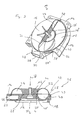
- blower 10 includes as essential components Fan housing 12 and on one axial side 14 of the same a feed wheel 16.
- the feed wheel 16 is by a not shown in the figures Drive motor, for example an electric motor, for rotation by one Axis of rotation A driven.
- the feed wheel 16 and the blower housing 12 limit one essentially on the axial side 14 of the blower housing 12 provided conveyor channel area 18.
- conveyor channel area 18 leads an entry area, which the entry of the to be promoted Medium, for example air. It also leads to promoting area an exit area, for example in the form of an exit channel or an outlet opening 20, out of which outlet opening 20 the medium to be delivered leaves the delivery channel area 18 can.
- the essentially toroidal structure and on the Fan housing 12 facing axial side open feed wheel 16 has a toroidal or ring-shaped shell 22, which in the circumferential direction around the axis of rotation A in succession a plurality of inclined conveyor blades 24 carries.
- this includes a protruding portion 28 which is on the radially outer portion the shell 22 of the feed wheel 16 is provided and axially, d. H. in the direction the axis of rotation A, protrudes beyond the other level of the feed wheel 16.
- This projection region 28 is in the circumferential direction about the axis of rotation A. preferably continuous, that is, uninterrupted.
- the delivery duct region 18 on the side 14 surrounding a depression formation 30 formed here in a step-like manner educated. It can be seen in the right half of FIG. 2 that one of the Shape or the extent of the projection region 28 corresponding step-like depression is formed, which is directed radially inwards to the Delivery channel area 18 is open, but radially outward through a peripheral wall 32 on the blower housing 12 is limited. This peripheral wall 32 of the depression region 30 and the projection region 28 on the feed wheel 16 lie at a short distance from one another in the radial direction across from.
- the ones addressed here Distances can be in the range of a few tenths of a millimeter.
- the Delivery channel area 18 radially outwards against the undesired Escape of medium to be conveyed contained therein under pressure sealed, so that an increased conveying efficiency of the blower thus formed 10 can be obtained.
- control openings 38 opening into the depression region 30 are provided. These control openings 38 are designed such that they are located at Viewing in the radial direction shows the depression 34, as well as the axial end of this depression base 34 opposite lying projection region 28.
- control openings 38 can be done, for example, with something larger Depth than the depression region 30 can be formed and if necessary can even flow into the subsidence 34, but not this fully enforce, so that another with a defined axial position provided base region 34 can be viewed from the radially outside can.
- FIG. 3 Another embodiment of a fan according to the invention is shown in Fig. 3 shown.
- Components described above Components in terms of structure and function correspond to the the same reference numerals.
- the depression region 30 and the projection region 28 thus form one the delivery channel area 18 radially outside or sealing Sealing area 42 of the labyrinth seal formation 26 during the Sink area 30 'and the protrusion area 28' one the conveyor channel area 18 sealing area 44 closing radially inwards form the labyrinth seal formation 26.
- the completion of the Delivery channel area 18 against the unwanted escape from below Medium under pressure and to be conveyed can be further improved.
- FIGS. 3 and 4 can also be used Embodiment the groove-like already mentioned above Control openings 38 are provided which again have a lateral or radial insight into the area of the depression base 34 of the depression area 30 to give the axial distance between this Sink bottom 34 and the opposite axial end face 36 to allow the projection formation 28. Because of the precise manufacturability the feed wheel 16 on the one hand and the blower housing 12 on the other hand, with correct relative positioning of the projection area 28 in the depression region 30 that it can be concluded that also in the radially inner area, the feed wheel 16 and the blower housing 12 face each other with the appropriate small axial distance.
- FIGS. 1 and 2 also Embodiment in which only the radially outer sealing area 42 is present, a groove-like depression area and assigned to this the projection area can be provided.
- Variant of the respective depression area 30 or 30 'with step-like So designed in the radial direction one-sided design his.
- this step-like configuration could also be such be that the peripheral wall provided on the fan housing 12 (in Fig. 2 peripheral wall 32) represents an outer peripheral wall, the is then surrounded by the associated projection area.
- the sealing area 44 which the Conveying channel area 18 seals radially inward.
Landscapes
- Engineering & Computer Science (AREA)
- Mechanical Engineering (AREA)
- General Engineering & Computer Science (AREA)
- Structures Of Non-Positive Displacement Pumps (AREA)
- Sealing Using Fluids, Sealing Without Contact, And Removal Of Oil (AREA)
Abstract
Description
- Fig. 1
- eine teilweise im Schnitt dargestellte perspektivische Ansicht eines erfindungsgemäßen Gebläses;
- Fig. 2
- eine Axialschnittansicht des in Fig. 1 dargestellten Gebläses;
- Fig. 3
- eine der Fig. 1 entsprechende Ansicht einer alternativen Ausgestaltungsart des erfindungsgemäßen Gebläses;
- Fig. 4
- eien Axialschnittansicht des in Fig. 3 dargestellten Gebläses.
Claims (9)
- Gebläse, insbesondere Verbrennungsluftgebläse für ein Fahrzeugheizgerät, umfassend ein Gebläsegehäuse (12) mit einem Eintrittsbereich und einem Austrittsbereich (20) für das zu fördernde Medium sowie ein Förderrad (16) mit einer Förderschaufelanordnung (24), wobei das Förderrad (16) an dem Gebläsegehäuse (12) zur Drehung um eine Drehachse (A) getragen ist und in Zusammenwirkung mit dem Gebläsegehäuse (12) einen Förderkanalbereich (18) begrenzt, wobei das Förderrad (16) und das Gebläsegehäuse (12) an ihren einander zugewandten Seiten eine den Förderkanalbereich (16) abschließende Labyrinthdichtungsformation (26) bilden.
- Gebläse nach Anspruch 1,
dadurch gekennzeichnet, dass an dem Förderrad (16) und dem Gebläsegehäuse (12) jeweils eine Dichtungsabschnittsanordnung (28, 30, 28', 30') gebildet ist, wobei die Dichtungsabschnittsanordnungen (28, 30, 28', 30') sich in axialer Richtung überlappen und in radialer Richtung einander benachbart liegen. - Gebläse nach Anspruch 1 oder 2,
dadurch gekennzeichnet, dass an einer Baugruppe (12) von Gebläsegehäuse (12) und Förderrad (16) eine um die Drehachse (A) umlaufende Einsenkungsformation (30, 30') vorgesehen ist und an der anderen Baugruppe (16) von Gebläsegehäuse (12) und Förderrad (16) eine in die Einsenkungsformation (30, 30') eingreifende Vorsprungsformation (28, 28') gebildet ist. - Gebläse nach Anspruch 3,
dadurch gekennzeichnet, dass die Einsenkungsformation (30') wenigstens bereichsweise nutartig ausgebildet ist. - Gebläse nach Anspruch 3 oder 4,
dadurch gekennzeichnet, dass die Einsenkungsformation (30) wenigstens bereichsweise stufenartig ausgebildet ist. - Gebläse nach einem der Ansprüche 3 bis 5,
dadurch gekennzeichnet, dass die Einsenkungsformation (30, 30') am Gebläsegehäuse (12) gebildet ist und die Vorsprungsformation (28, 28') am Förderrad (16) gebildet ist. - Gebläse nach einem der Ansprüche 3 bis 6,
dadurch gekennzeichnet, dass ein Abstandskontrollbereich (38) vorgesehen ist, in welchem ein Axialrelativlage der Vorsprungsformation (28) bezüglich der Eingriffsformation (30) überprüfbar ist. - Gebläse nach Anspruch 7,
dadurch gekennzeichnet, dass der Abstandskontrollbereich (38) wenigstens eine in die Einsenkungsformation (30) einmündende und die Ermittlung eines Axialabstandes zwischen einem Einsenkungsgrund (34) der Einsenkungsformation (30) und der diesem Einsenkungsgrund (34) axial gegenüber liegenden Vorsprungsformation (28) zulassende Kontrollöffnung (38) umfasst. - Gebläse nach einem der Ansprüche 1 bis 8,
dadurch gekennzeichnet, dass die Labyrinthdichtungsformation (26) einen radial außerhalb des Förderkanalbereichs (18) liegenden ersten Dichtungsbereich (42) oder/und einen radial innerhalb des Förderkanalbereichs (18) liegenden zweiten Dichtungsbereich (44) umfasst.
Applications Claiming Priority (2)
| Application Number | Priority Date | Filing Date | Title |
|---|---|---|---|
| DE2003115779 DE10315779A1 (de) | 2003-04-07 | 2003-04-07 | Gebläse, insbesondere Verbrennungsluftgebläse für ein Fahrzeugheizgerät |
| DE10315779 | 2003-04-07 |
Publications (2)
| Publication Number | Publication Date |
|---|---|
| EP1467102A1 true EP1467102A1 (de) | 2004-10-13 |
| EP1467102B1 EP1467102B1 (de) | 2007-03-07 |
Family
ID=32864362
Family Applications (1)
| Application Number | Title | Priority Date | Filing Date |
|---|---|---|---|
| EP20040008507 Expired - Lifetime EP1467102B1 (de) | 2003-04-07 | 2004-04-07 | Gebläse |
Country Status (3)
| Country | Link |
|---|---|
| EP (1) | EP1467102B1 (de) |
| JP (1) | JP2004308653A (de) |
| DE (2) | DE10315779A1 (de) |
Cited By (2)
| Publication number | Priority date | Publication date | Assignee | Title |
|---|---|---|---|---|
| EP1655495A1 (de) * | 2004-11-05 | 2006-05-10 | J. Eberspächer GmbH Co. KG | Seitenkanalgebläse |
| EP4339466A1 (de) * | 2022-09-14 | 2024-03-20 | Vaillant GmbH | Heizgerät mit gebläse |
Families Citing this family (1)
| Publication number | Priority date | Publication date | Assignee | Title |
|---|---|---|---|---|
| FR3055368B1 (fr) | 2016-08-24 | 2018-08-24 | Peugeot Citroen Automobiles Sa | Dispositif de refroidissement de systeme de suralimentation d’air de moteur thermique, et systeme de suralimentation d’air equipe d'un tel dispositif |
Citations (8)
| Publication number | Priority date | Publication date | Assignee | Title |
|---|---|---|---|---|
| DE874503C (de) * | 1939-12-19 | 1953-04-23 | Siemens Ag | Umlaufpumpe fuer Gasfoerderung |
| US3382809A (en) * | 1967-09-12 | 1968-05-14 | Ford Motor Co | Control for fluid pump bypass |
| US3964888A (en) * | 1973-10-01 | 1976-06-22 | Robert Bosch G.M.B.H. | Vacuum sweeper |
| DE19720281A1 (de) * | 1997-05-15 | 1998-11-19 | Eberspaecher J Gmbh & Co | Mit Flüssigbrennstoff betriebenes Luftheizgerät, insbesondere Zuheizer für Kraftfahrzeuge |
| DE19849836C1 (de) * | 1998-10-29 | 1999-10-21 | Webasto Thermosysteme Gmbh | Ringkanalgebläse und Verfahren zur Montage eines solchen |
| DE19847522C1 (de) * | 1998-10-15 | 1999-11-04 | Webasto Thermosysteme Gmbh | Ringkanalgebläse |
| DE19906515C1 (de) * | 1999-02-17 | 2000-02-03 | Webasto Thermosysteme Gmbh | Seitenkanalgebläse |
| DE19921765A1 (de) * | 1999-05-11 | 2000-11-23 | Siemens Ag | Seitenkanalmaschine |
Family Cites Families (2)
| Publication number | Priority date | Publication date | Assignee | Title |
|---|---|---|---|---|
| US1686549A (en) * | 1925-12-11 | 1928-10-09 | Arthur W Burks | Pump |
| DE19720282B4 (de) * | 1997-05-15 | 2007-09-27 | J. Eberspächer GmbH & Co. KG | Mit Flüssigbrennstoff betriebenes Luftheizgerät, insbesondere Zuheizer für Kraftfahrzeuge |
-
2003
- 2003-04-07 DE DE2003115779 patent/DE10315779A1/de not_active Ceased
-
2004
- 2004-03-24 JP JP2004086793A patent/JP2004308653A/ja active Pending
- 2004-04-07 DE DE200450003095 patent/DE502004003095D1/de not_active Expired - Lifetime
- 2004-04-07 EP EP20040008507 patent/EP1467102B1/de not_active Expired - Lifetime
Patent Citations (8)
| Publication number | Priority date | Publication date | Assignee | Title |
|---|---|---|---|---|
| DE874503C (de) * | 1939-12-19 | 1953-04-23 | Siemens Ag | Umlaufpumpe fuer Gasfoerderung |
| US3382809A (en) * | 1967-09-12 | 1968-05-14 | Ford Motor Co | Control for fluid pump bypass |
| US3964888A (en) * | 1973-10-01 | 1976-06-22 | Robert Bosch G.M.B.H. | Vacuum sweeper |
| DE19720281A1 (de) * | 1997-05-15 | 1998-11-19 | Eberspaecher J Gmbh & Co | Mit Flüssigbrennstoff betriebenes Luftheizgerät, insbesondere Zuheizer für Kraftfahrzeuge |
| DE19847522C1 (de) * | 1998-10-15 | 1999-11-04 | Webasto Thermosysteme Gmbh | Ringkanalgebläse |
| DE19849836C1 (de) * | 1998-10-29 | 1999-10-21 | Webasto Thermosysteme Gmbh | Ringkanalgebläse und Verfahren zur Montage eines solchen |
| DE19906515C1 (de) * | 1999-02-17 | 2000-02-03 | Webasto Thermosysteme Gmbh | Seitenkanalgebläse |
| DE19921765A1 (de) * | 1999-05-11 | 2000-11-23 | Siemens Ag | Seitenkanalmaschine |
Cited By (2)
| Publication number | Priority date | Publication date | Assignee | Title |
|---|---|---|---|---|
| EP1655495A1 (de) * | 2004-11-05 | 2006-05-10 | J. Eberspächer GmbH Co. KG | Seitenkanalgebläse |
| EP4339466A1 (de) * | 2022-09-14 | 2024-03-20 | Vaillant GmbH | Heizgerät mit gebläse |
Also Published As
| Publication number | Publication date |
|---|---|
| EP1467102B1 (de) | 2007-03-07 |
| JP2004308653A (ja) | 2004-11-04 |
| DE10315779A1 (de) | 2004-11-04 |
| DE502004003095D1 (de) | 2007-04-19 |
Similar Documents
| Publication | Publication Date | Title |
|---|---|---|
| DE4318122C2 (de) | Aggregat zum Fördern von Kraftstoff aus einem Vorratstank zur Brennkraftmaschine eines Kraftfahrzeugs | |
| DE102007053016A1 (de) | Seitenkanalverdichter | |
| DE69104455T2 (de) | Regenerativkreiselverdichter. | |
| DE102009006652B4 (de) | Seitenkanalgebläse, insbesondere Sekundärluftgebläse für eine Verbrennungskraftmaschine | |
| DE19904560A1 (de) | Elektrisch angetriebene Kraftstoffpumpe mit sich verengendem Pumpkanal | |
| EP0589300B1 (de) | Radialgebläse | |
| WO2017050427A1 (de) | Lüftereinheit | |
| EP4198261A1 (de) | Schraubenspindelpumpe | |
| EP2322803B1 (de) | Pumpe mit einer magnetkupplung | |
| EP2737215A1 (de) | Seitenkanalgebläse mit mehreren, über den umfang verteilten förderkanälen | |
| EP0297615B1 (de) | Drehgelenkkupplung | |
| EP0344516A1 (de) | Mehrstufiger Seitenkanalverdichter | |
| EP1467102B1 (de) | Gebläse | |
| DE102019101277A1 (de) | Axiallüfteranordnung für Fahrzeuge | |
| DE4415566C2 (de) | Seitenkanalpumpe | |
| WO2019120550A1 (de) | Seitenkanalgebläse, insbesondere sekundärluftgebläse für eine verbrennungskraftmaschine | |
| EP1420196A2 (de) | Sperrdruckdichtung mit Pumpfunktion | |
| DE1476870A1 (de) | Axialkompressor fuer Gasturbinenstrahltriebwerke | |
| EP0692075A1 (de) | Pumpenstufe in blechbauweise | |
| WO2007048451A1 (de) | Turbolader | |
| DE102014118210B4 (de) | Mehrflutige Strömungsmaschine | |
| EP1797333B1 (de) | Lüfter mit einem lüfterrad | |
| EP2342465B1 (de) | Seitenkanalgebläse, insbesondere sekundärluftgebläse für eine verbrennungskraftmaschine | |
| EP3728860B1 (de) | Seitenkanalgebläse, insbesondere sekundärluftgebläse für eine verbrennungskraftmaschine | |
| WO2025016731A1 (de) | Magnetkupplungspumpenanordnung mit spalttopf und verfahren zur herstellung des spalttopfes |
Legal Events
| Date | Code | Title | Description |
|---|---|---|---|
| PUAI | Public reference made under article 153(3) epc to a published international application that has entered the european phase |
Free format text: ORIGINAL CODE: 0009012 |
|
| AK | Designated contracting states |
Kind code of ref document: A1 Designated state(s): AT BE BG CH CY CZ DE DK EE ES FI FR GB GR HU IE IT LI LU MC NL PL PT RO SE SI SK TR |
|
| AX | Request for extension of the european patent |
Extension state: AL HR LT LV MK |
|
| 17P | Request for examination filed |
Effective date: 20041001 |
|
| AKX | Designation fees paid |
Designated state(s): DE GB SE |
|
| GRAP | Despatch of communication of intention to grant a patent |
Free format text: ORIGINAL CODE: EPIDOSNIGR1 |
|
| GRAS | Grant fee paid |
Free format text: ORIGINAL CODE: EPIDOSNIGR3 |
|
| GRAA | (expected) grant |
Free format text: ORIGINAL CODE: 0009210 |
|
| AK | Designated contracting states |
Kind code of ref document: B1 Designated state(s): DE GB SE |
|
| REG | Reference to a national code |
Ref country code: GB Ref legal event code: FG4D Free format text: NOT ENGLISH |
|
| REF | Corresponds to: |
Ref document number: 502004003095 Country of ref document: DE Date of ref document: 20070419 Kind code of ref document: P |
|
| REG | Reference to a national code |
Ref country code: SE Ref legal event code: TRGR |
|
| GBT | Gb: translation of ep patent filed (gb section 77(6)(a)/1977) |
Effective date: 20070611 |
|
| PLBE | No opposition filed within time limit |
Free format text: ORIGINAL CODE: 0009261 |
|
| STAA | Information on the status of an ep patent application or granted ep patent |
Free format text: STATUS: NO OPPOSITION FILED WITHIN TIME LIMIT |
|
| 26N | No opposition filed |
Effective date: 20071210 |
|
| PGFP | Annual fee paid to national office [announced via postgrant information from national office to epo] |
Ref country code: SE Payment date: 20080424 Year of fee payment: 5 |
|
| PGFP | Annual fee paid to national office [announced via postgrant information from national office to epo] |
Ref country code: GB Payment date: 20080423 Year of fee payment: 5 |
|
| EUG | Se: european patent has lapsed | ||
| GBPC | Gb: european patent ceased through non-payment of renewal fee |
Effective date: 20090407 |
|
| PG25 | Lapsed in a contracting state [announced via postgrant information from national office to epo] |
Ref country code: GB Free format text: LAPSE BECAUSE OF NON-PAYMENT OF DUE FEES Effective date: 20090407 |
|
| PG25 | Lapsed in a contracting state [announced via postgrant information from national office to epo] |
Ref country code: SE Free format text: LAPSE BECAUSE OF NON-PAYMENT OF DUE FEES Effective date: 20090408 |
|
| REG | Reference to a national code |
Ref country code: DE Ref legal event code: R082 Ref document number: 502004003095 Country of ref document: DE Representative=s name: WEICKMANN & WEICKMANN, DE |
|
| REG | Reference to a national code |
Ref country code: DE Ref legal event code: R081 Ref document number: 502004003095 Country of ref document: DE Owner name: EBERSPAECHER CLIMATE CONTROL SYSTEMS GMBH & CO, DE Free format text: FORMER OWNER: J. EBERSPAECHER GMBH & CO. KG, 73730 ESSLINGEN, DE Effective date: 20130607 Ref country code: DE Ref legal event code: R082 Ref document number: 502004003095 Country of ref document: DE Representative=s name: WEICKMANN & WEICKMANN, DE Effective date: 20130607 Ref country code: DE Ref legal event code: R082 Ref document number: 502004003095 Country of ref document: DE Representative=s name: RUTTENSPERGER LACHNIT TROSSIN GOMOLL PATENT- U, DE Effective date: 20130607 |
|
| REG | Reference to a national code |
Ref country code: DE Ref legal event code: R082 Ref document number: 502004003095 Country of ref document: DE Representative=s name: RUTTENSPERGER LACHNIT TROSSIN GOMOLL PATENT- U, DE |
|
| PGFP | Annual fee paid to national office [announced via postgrant information from national office to epo] |
Ref country code: DE Payment date: 20160430 Year of fee payment: 13 |
|
| REG | Reference to a national code |
Ref country code: DE Ref legal event code: R119 Ref document number: 502004003095 Country of ref document: DE |
|
| PG25 | Lapsed in a contracting state [announced via postgrant information from national office to epo] |
Ref country code: DE Free format text: LAPSE BECAUSE OF NON-PAYMENT OF DUE FEES Effective date: 20171103 |