EP1466814A2 - Drive assist system for motor vehicles - Google Patents
Drive assist system for motor vehicles Download PDFInfo
- Publication number
- EP1466814A2 EP1466814A2 EP04076506A EP04076506A EP1466814A2 EP 1466814 A2 EP1466814 A2 EP 1466814A2 EP 04076506 A EP04076506 A EP 04076506A EP 04076506 A EP04076506 A EP 04076506A EP 1466814 A2 EP1466814 A2 EP 1466814A2
- Authority
- EP
- European Patent Office
- Prior art keywords
- lane
- vehicle
- judging
- moving
- warning
- Prior art date
- Legal status (The legal status is an assumption and is not a legal conclusion. Google has not performed a legal analysis and makes no representation as to the accuracy of the status listed.)
- Granted
Links
- 230000007274 generation of a signal involved in cell-cell signaling Effects 0.000 claims abstract description 23
- 239000003550 marker Substances 0.000 description 8
- 238000012545 processing Methods 0.000 description 6
- 230000003287 optical effect Effects 0.000 description 4
- 238000000034 method Methods 0.000 description 3
- 230000002265 prevention Effects 0.000 description 3
- 238000001514 detection method Methods 0.000 description 2
- 238000005516 engineering process Methods 0.000 description 2
- 238000011156 evaluation Methods 0.000 description 2
- 238000002474 experimental method Methods 0.000 description 2
- 238000005259 measurement Methods 0.000 description 2
- 238000012544 monitoring process Methods 0.000 description 2
- 206010041349 Somnolence Diseases 0.000 description 1
- 230000008859 change Effects 0.000 description 1
- 238000010586 diagram Methods 0.000 description 1
- 231100001261 hazardous Toxicity 0.000 description 1
- 238000012986 modification Methods 0.000 description 1
- 230000004048 modification Effects 0.000 description 1
- 230000008569 process Effects 0.000 description 1
- 230000004044 response Effects 0.000 description 1
- 239000013598 vector Substances 0.000 description 1
Images


Classifications
-
- G—PHYSICS
- G05—CONTROLLING; REGULATING
- G05D—SYSTEMS FOR CONTROLLING OR REGULATING NON-ELECTRIC VARIABLES
- G05D1/00—Control of position, course or altitude of land, water, air, or space vehicles, e.g. automatic pilot
- G05D1/02—Control of position or course in two dimensions
- G05D1/021—Control of position or course in two dimensions specially adapted to land vehicles
- G05D1/0231—Control of position or course in two dimensions specially adapted to land vehicles using optical position detecting means
- G05D1/0246—Control of position or course in two dimensions specially adapted to land vehicles using optical position detecting means using a video camera in combination with image processing means
- G05D1/0251—Control of position or course in two dimensions specially adapted to land vehicles using optical position detecting means using a video camera in combination with image processing means extracting 3D information from a plurality of images taken from different locations, e.g. stereo vision
-
- B—PERFORMING OPERATIONS; TRANSPORTING
- B62—LAND VEHICLES FOR TRAVELLING OTHERWISE THAN ON RAILS
- B62D—MOTOR VEHICLES; TRAILERS
- B62D1/00—Steering controls, i.e. means for initiating a change of direction of the vehicle
- B62D1/24—Steering controls, i.e. means for initiating a change of direction of the vehicle not vehicle-mounted
- B62D1/28—Steering controls, i.e. means for initiating a change of direction of the vehicle not vehicle-mounted non-mechanical, e.g. following a line or other known markers
-
- B—PERFORMING OPERATIONS; TRANSPORTING
- B62—LAND VEHICLES FOR TRAVELLING OTHERWISE THAN ON RAILS
- B62D—MOTOR VEHICLES; TRAILERS
- B62D15/00—Steering not otherwise provided for
-
- B—PERFORMING OPERATIONS; TRANSPORTING
- B62—LAND VEHICLES FOR TRAVELLING OTHERWISE THAN ON RAILS
- B62D—MOTOR VEHICLES; TRAILERS
- B62D15/00—Steering not otherwise provided for
- B62D15/02—Steering position indicators ; Steering position determination; Steering aids
- B62D15/029—Steering assistants using warnings or proposing actions to the driver without influencing the steering system
-
- B—PERFORMING OPERATIONS; TRANSPORTING
- B60—VEHICLES IN GENERAL
- B60T—VEHICLE BRAKE CONTROL SYSTEMS OR PARTS THEREOF; BRAKE CONTROL SYSTEMS OR PARTS THEREOF, IN GENERAL; ARRANGEMENT OF BRAKING ELEMENTS ON VEHICLES IN GENERAL; PORTABLE DEVICES FOR PREVENTING UNWANTED MOVEMENT OF VEHICLES; VEHICLE MODIFICATIONS TO FACILITATE COOLING OF BRAKES
- B60T2201/00—Particular use of vehicle brake systems; Special systems using also the brakes; Special software modules within the brake system controller
- B60T2201/08—Lane monitoring; Lane Keeping Systems
- B60T2201/082—Lane monitoring; Lane Keeping Systems using alarm actuation
Definitions
- the present invention relates to a drive assist system for raising an alarm when a vehicle moves out from the lane and more particularly to a drive assist system capable of controlling the alarm according to situations.
- ADA Active Drive Assist
- a lane moving-out prevention technique which is one of the functions of the ADA system is for informing drivers of this hazard by a warning device and the like, when vehicles come close to the lane marker or move out therefrom due to drivers' inadvertent behaviour such as sudden drowsiness overcoming drivers or inattentive driving.
- Various technologies have been developed to prevent the moving-out from the lane in these circumstances.
- Japanese Patent Application JP-A-7-65 296 (Laid open No. Toku-Kai-Hei 7-65296) discloses a technology wherein an alarm is raised only when the vehicle moves out from the lane without operating the turn signal lever.
- drivers do not always operate the turn signal lever when moving out from the lane.
- drivers may move out from the lane without having the opportunity to operate the turn signal lever.
- an alarm is raised in the same manner regardless of drivers' intention.
- the warning device of the ADA system is stopped or suppressed (for example, in case of a sound-based warning device, reduce the sound level, change the tone of the sound, stop the sound and the like) according the necessity of the warning.
- a drive assist system for raising an alarm when a vehicle moves out from a first lane on which it is travelling comprising:
- the warning signal generation judging means can output a signal to raise an alarm when said vehicle moves out from said first lane in the direction of a neighboring lane to said first lane and at least when it is judged based on said information obtained from said running environment judging section that an object exists on said neighboring lane and that said object is an obstacle to said vehicle.
- the road/object detecting section 11 detects lane markers, other vehicles, objects other than vehicles and the like separately from the distance images inputted from the image processing section 4 and obtains the image data of the road and objects.
- lane markers H 1 , H 3 , H 2 left and right ones and a center one, respectively
- a preceding vehicle M 1 travelling on the driver's lane ie.
- the warning signal generation judging section 13 comprises a roadside judging section 13a, a moving-out direction obstacle judging section 13b, a lane width judging section 13c and a front direction obstacle judging section 13d.
- the moving-out direction obstacle judging section 13b is started to operate based on the judgment "there is a lane" in the roadside judging section 13a.
- the moving-out direction obstacle judging section 13b operates, based on data from the road/object detecting section 11 and data from the vehicle speed sensor 5, if an object exists on a "moving out direction" lane, it is judged whether or not the object is an obstacle to the self vehicle. If the object is an obstacle, a signal for raising an alarm is outputted to the warning control section 14 and if the object is not an obstacle, the lane width judging section 13c is started to operate.
- the lane width judging section 13c starts to operate based on the judgment " there is no obstacle in the moving out direction lane" in the moving-out direction obstacle judging section 13b.
- the lane width judging section 13c operates, based on data from the road/object detecting section 11, it is judged whether or not the width "B" of the driver's lane is broader than a predetermined width "B cl ".
- the lane moving-out is judged to be inevitable because of the narrow width of the lane and a signal for stopping or suppressing an alarm is outputted to the warning control section 14.
- This predetermined width "B cl " is a value for judging a narrow road and in this embodiment the value is established to be 3.5 meters for example.
- the front direction obstacle judging section 13d operates, based on data from the road/object detecting section 11 and data from the vehicle speed sensor 5, in the case where there an object (or objects) is caught within a pre-established monitoring range, it is judged whether or not this object (or objects) is an obstacle to the driver's vehicle. If it is judged that the object is an obstacle, a signal for stopping or suppressing an alarm is outputted to the warning control section 14 and if it is judged that the object is not an obstacle, a signal for raising an alarm is outputted to the warning control section 14.
- Figs. 6a through 6e Situations in which a driver is likely to take an avoidance behavior are shown in Figs. 6a through 6e.
- Fig. 6a illustrates a situation wherein the vehicle has a preceding vehicle ahead or is coming close to the preceding vehicle
- Fig. 6b illustrates a situation wherein the vehicle is coming close to a parked vehicle
- Fig. 6c illustrates a situation wherein the vehicle encounters a jumping-out vehicle or pedestrian
- Fig. 6d illustrates wherein the vehicle is coming close to a pedestrian
- Fig. 6e illustrates a situation wherein the vehicle is coming close to an oncoming vehicle or a vehicle traveling ahead in the same direction.
- the pre-established monitoring range must include, as shown in Fig. 7, not only the driver's lane (width B) but also the left and right ranges having a width "A" (for example 0.3 meters) respectively which cover the neighboring left and right lanes.
- the width "A" may be a fixed value or may be a value established by a map or formula parameterizing the vehicle speed v 1 .
- the judgment whether the object situated in front of the driver's vehicle is an obstacle or not is performed in the following manner for example:
- v 1 is the velocity of the driver's vehicle 1
- v 3 is the velocity of the object situated in front of the driver's vehicle.
- the warning control section 14 which serves as a warning control means operates a buzzer responsive to signals from the warning signal generation judging section 13.
- the CCD camera optical system 3 images pictures in front of the driver's vehicle and produces distance images presenting three-dimensional distance distribution in the image processing section 4. Further, the vehicle speed sensor 5 detects the vehicle speed v 1 of the driver's vehicle 1.
- the program goes to S105 where the roadside judging section 13a of the warning signal generation judging section 13 judges whether or not there is a lane in the moving-out direction. If there is no lane in the moving-out direction (in case of a lane on the roadside), the program skips to S 116 where a signal for raising an alarm is outputted to the warning control section 14.
- the program goes to S 106 where it is judged whether or not an object (or objects) exists in the moving-out direction lane based on the data from the road/object detecting section 11. If no object is found, that is, since there is no obstacle, the program skips to S 109 and if an object (or obj ects) is found, the program steps to S107.
- the width "B" of the driver's lane is calculated based on data from the road/object detecting section 11 and after that the program goes to S110 where the width "B" of the driver's lane is compared with a predetermined width "B cl ".
- the lane moving-out is judged to be unavoidable due to the narrow width of the lane and the program skips to S115 where a signal for stopping or suppressing an alarm is outputted to the warning control section 14.
- the program goes to S111.
- the steps S109, S110 are ones performed in the lane width judging section 13c of the warning signal generation judging section 13.
- detecting ranges "A” (respective detecting ranges along the left and right neighboring lanes) are established based on data from the road/object detecting section 11 and data from the vehicle speed sensor 5 and an overall detecting range "C", including the lane width "B” and the left and right detecting ranges "A”, is determined.
- the program goes to S112 where it is judged whether or not an object (or objects) exists within the overall detecting range "C" based on the data from the road/object detecting section 11. If there is no object within the range "C", that is, no obstacle exists in the frontal direction of the vehicle, since it is judged that the vehicle has tried a mere lane moving-out, the program skips to S116 where a signal for raising an alarm is outputted to the warning control section 14.
- step S114 if the distance l 2 is larger than the obstacle judging distance L 2 (l 2 (L 2 ), since it is judged that this is a mere lane moving-out, the program goes to S116 where a signal for raising an alarm is outputted to the warning control section 14. That is, steps S111, S112, S113, S 114 are ones performed in the front direction obstacle judging section 13d of the warning signal generation judging section 13.
- the drive assist system can call a driver's attention by raising an alarm when the driver's vehicle moves out from the lane in the roadside direction. Further, in the case where the vehicle tries to enter a neighboring lane, the drive assist system can call a driver's attention by raising an alarm when there is a possibility of colliding with an obstacle such as an oncoming vehicle. Further, in the case where the vehicle moves out from the lane unavoidably due to the narrow width of the lane, the drive assist system can stop or suppress an alarm. Further, in case where the vehicle moves out from the lane to avoid an obstacle existing in front of the vehicle, the drive assist system can stop or suppress an alarm.
- the warning device may include any kind of warning devices such as a buzzer, a warning light, a display, an announcing device and the like. Further, in addition to the warning device, an automatic brake system capable of braking automatically may be utilized.
- the drive assist system can have a lane moving-out warning function having a natural feeling and capable of reflecting a driver's intention.
Abstract
Description
- The present invention relates to a drive assist system for raising an alarm when a vehicle moves out from the lane and more particularly to a drive assist system capable of controlling the alarm according to situations.
- The concept exists of improving the safety of a vehicle by positively assisting a driver's operation and a system for introducing this idea is the so-called Active Drive Assist (ADA) System. A primary function of the ADA system is to anticipate a hazard of a collision with a forward vehicle, a hazard of a contact with an object, a possibility of a moving-out from a lane of a road and the like, based on surrounding information or running conditions of a vehicle and to inform the driver of these hazardous possibilities or to activate various control devices.
- There are known apparatuses employing a laser radar and the like to collect surrounding information. Further, the inventor of the present invention proposes, in Japanese Patent Application Laid-open No. Toku-Kai-Hei 5-265547, a technique in which picture images taken by cameras of the scenery in front of the vehicle are processed to recognize road and traffic conditions in the form of three-dimensional information.
- A lane moving-out prevention technique which is one of the functions of the ADA system is for informing drivers of this hazard by a warning device and the like, when vehicles come close to the lane marker or move out therefrom due to drivers' inadvertent behaviour such as sudden drowsiness overcoming drivers or inattentive driving. Various technologies have been developed to prevent the moving-out from the lane in these circumstances.
- However, in the real world, there are cases where drivers are required to negotiate roads crowded with pedestrians or parked vehicles and as a result, drivers often move out of lanes to avoid a contact with those pedestrians or parked vehicles.
- In order to make this type of ADA system more practicable, these drivers' intentional behaviour must be discriminated from inadvertent ones as described above to control or suppress the issuance of alarms.
- With respect to the ADA system capable of reflecting drivers' intention, Japanese Patent Application JP-A-7-65 296 (Laid open No. Toku-Kai-Hei 7-65296) discloses a technology wherein an alarm is raised only when the vehicle moves out from the lane without operating the turn signal lever.
- However, drivers do not always operate the turn signal lever when moving out from the lane. For example, when the vehicle travels on ordinary roads, in a case where some other vehicle or an obstacle jumps out in front of the vehicle, drivers may move out from the lane without having the opportunity to operate the turn signal lever. According to the prior art, in such a case, an alarm is raised in the same manner regardless of drivers' intention.
- Therefore, in order to make the ADA system more usable, it is required that the warning device of the ADA system is stopped or suppressed (for example, in case of a sound-based warning device, reduce the sound level, change the tone of the sound, stop the sound and the like) according the necessity of the warning.
- There is known from DE-A-195 07 957 (preamble of claim 1) a vehicle with a laterally mounted optical scanning device for zero-contact scanning of a lateral highway area and an evaluation unit connected thereto. The optical scanning device comprises a linear array of infrared transmitting devices located side by side and a corresponding CCD array, and the connected evaluation unit is programmed to perform time measurement, contrast measurement, and contour recognition. This optical scanning system enables detection of running conditions of the vehicle, the position of the vehicle, the position of a first lane in which the vehicle is running and the position of a neighbouring lane and for recognizing objects existing on the first lane, and the neighbouring lane in relationship to the position of the vehicle. It also enables the provision of a means for judging lane moving-out by comparing the position of the vehicle with the position of the first lane and issuing a corresponding warning signal.
- It is one feature of the present invention to provide a drive assist system capable of stopping or suppressing an alarm in the case of an intentional lane moving-out.
- In accordance with the present invention, there is provided a drive assist system for raising an alarm when a vehicle moves out from a first lane on which it is travelling, comprising:
- a running environment detecting means for detecting running conditions of said vehicle, the position of said vehicle, the position of said first lane and the position of a neighboring lane and for recognizing objects existing on said first lane and said neighboring lane in relationship to said position of said vehicle;
- a lane moving-out judging means based on information obtained from said running environment detecting means for comparing said position of said vehicle with said position of said first lane and for judging a lane moving-out from said first lane of said vehicle;
- a warning signal generation judging means which outputs a signal to stop or suppress an alarm when said vehicle moves out from said first lane and at least when it is judged based on said information obtained from said running environment judging section that an object exists on said first lane within a pre-established range and that said object is an obstacle to said vehicle; and
- a warning control means for operating an warning device based on said signal from said warning signal generation judging means.
-
- Advantageously, said pre-established range in said warning signal generation judging means includes the width of said first lane and a specified width of a range provided on left and right sides of said first lane, respectively.
- In one embodiment, the warning signal generation judging means can output a signal to raise an alarm when said vehicle moves out from said first lane in the direction of a neighboring lane to said first lane and at least when it is judged based on said information obtained from said running environment judging section that an object exists on said neighboring lane and that said object is an obstacle to said vehicle.
- In another embodiment, the warning signal generation judging means can output a signal to raise an alarm when said vehicle moves out from said first lane and at least when it is judged based on said information obtained from said running environment judging means that said neighboring lane does not exist in the direction of moving out.
- The invention is described further hereinafter, by way of example only, with reference to the accompanying drawings, in which:-
- Fig. 1 is a functional block diagram of a drive assist system according to the present invention;
- Fig. 2 is a schematic drawing of a drive assist system according to the present invention;
- Fig. 3 is an explanatory view of data detected by a road/object detecting section;
- Fig. 4 is a view for explaining a judgment of a lane moving out;
- Fig. 5a is an explanatory view showing a relationship between a vehicle and an oncoming vehicle;
- Fig. 5b is an explanatory view showing a relationship between a vehicle fitted with a system in accordance with the present invention (the "driver's vehicle") and a preceding vehicle;
- Figs. 6a through 6e are views showing examples of various cases where there is a possibility of avoiding obstacles;
- Fig. 7 is an explanatory view showing a range of detection;
- Fig. 8 is a flowchart of a drive assist control; and
- Fig. 9 is a flowchart continued from Fig. 8.
-
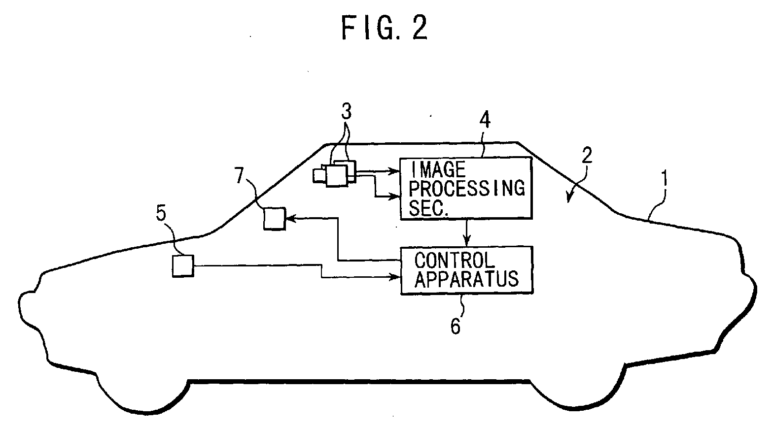
- Referring now to Fig. 2,
numeral 1 denotes a vehicle (referred to hereinafter as the "driver's vehicle") on which adrive assist system 2 according to the present invention is mounted. Thedrive assist system 2 has the function of lane moving-out prevention in which a warning is raised when the vehicle comes close to the lane marker of a road. - The
drive assist system 2 has a pair ofCCD cameras 3 disposed in the frontal portion of the passenger compartment at a specified transversal interval on the left and right sides of thevehicle 1 in order to take stereoscopic pictures of the scenery at the front of thevehicle 1 from different view points. - The
CCD cameras 3 are connected with animage processing section 4 in which three-dimensional distance distribution data are formed based on pictures of the scenery taken by theCCD cameras 3. Further, theimage processing section 4 is connected with acontrol apparatus 6 for outputting a warning signal to awarning device 7 based on the distance distribution data and a vehicle speed v1 of the vehicle when thevehicle 1 moves out of the lane marker. The vehicle speed v1 is detected by avehicle speed sensor 5 and sent to thecontrol apparatus 6. - The
image processing section 4 calculates distance information over an entire image based on the deviation amount of a corresponding position with respect to a pair of the stereoscopic pictures taken by theCCD cameras 3 according to the principle of triangulation and forms distance images presenting three-dimensional distribution based on the distance information to output these distance images to thecontrol apparatus 6. - The
control apparatus 6 is formed by a multi-microprocessor system in which necessary information is extracted from the distance images processed in theimage processing section 4 and a lane moving-out prevention control is performed based on the vehicle speed v1 detected by thevehicle speed sensor 5. - Further, as shown in Fig. 1, the
control apparatus 6 comprises a road/object detecting section 11, a lane moving-outjudging section 12, a warning signal generation judging section 13 and awarning control section 14. - The road/
object detecting section 11 detects lane markers, other vehicles, objects other than vehicles and the like separately from the distance images inputted from theimage processing section 4 and obtains the image data of the road and objects. In the case of a road with two lanes as shown in Fig. 3, for example, the position and the configuration of lane markers H1, H3, H2 (left and right ones and a center one, respectively), a preceding vehicle M1 travelling on the driver's lane, ie. the road lane on which the "driver's vehicle" is running, a parked vehicle M2, an oncoming vehicle M3 travelling on the counter lane, a vehicle M4 crossing the driver's lane, a pedestrian S1 crossing the road, a pedestrian S2 walking along the lane and the other obstacle S3 are obtained based on the image data in terms of coordinates X, Y on a coordinate system composed of an X coordinate axis in the vehicle travelling direction and a Y coordinate axis which is perpendicular to the X coordinate axis X. Further, data on velocity vectors for those objects M1, M2, M3, M4, S1, S2 and S3 are also calculated. - Thus, a running environment detecting means is formed by the
vehicle speed sensor 5, a pair of theCCD cameras 3, theimage processor 4 and the road/object detecting section 11. - The lane moving-out
judging section 12 serving as a lane moving-out judging means receives the data from the road/object detecting section 11 and judges whether or not thevehicle 1 is moving out from the lane marker by comparing the coordinates (0, 0) showing the reference position of thevehicle 1 with either of the coordinates (0, y) l(n)) of the left-hand lane marker H1 or the coordinates (0, yr(n)) of the right-hand lane marker H2. - That is, for example, as shown in Fig. 4, letting the width of the
vehicle 1 be T, if yl(n)≥ - T/2, it is judged that the vehicle is moving-out from the left-hand lane marker and if yr(n)≤ - T/2, it is judged that the vehicle is moving out from the right-hand lane marker. The result of the judgment is outputted to the warning signal generation judging section 13. - The warning signal generation judging section 13 receives signals from the
vehicle speed sensor 5, the road/object detecting section 11 and the lane moving-outjudging section 12 and in the case where the signal from the lane moving-outjudging section 12 is "the vehicle is not moving out from the lane", a signal for stopping the warning is outputted to thewarning control section 14. On the other hand, in the case where the signal from the lane moving-outjudging section 12 is "the vehicle is moving out from the lane", either a signal for raising the warning or a signal for controlling (stopping or suppressing) is outputted to thewarning control section 14. Thus, the warning signal generation judging section 13 serves as a warning signal generation judging means. - The warning signal generation judging section 13 comprises a
roadside judging section 13a, a moving-out directionobstacle judging section 13b, a lanewidth judging section 13c and a front directionobstacle judging section 13d. - The
roadside judging section 13a starts to operate in response to the signal "the vehicle is moving out from the lane" of the lane moving-outjudging section 12. When thisroadside judging section 13a operates, based on data from the road/obstacle detecting section 11, it is judged whether or not a lane exists in the direction of "moving out". If a lane does not exist, a signal for raising an alarm is outputted to thewarning control section 14. If a lane exists, the moving-out directionobstacle judging section 13b is operated. For example, in the case shown in Fig. 4, when the vehicle moves out from the lane to the right, it is judged that a lane exists and then the moving-out directionobstacle judging section 13b is started to operate. On the other hand, when the vehicle moves out from the lane to the left, it is judged that there is no lane and then a signal for raising an alarm is outputted to thewarning control section 14. - The moving-out direction
obstacle judging section 13b is started to operate based on the judgment "there is a lane" in theroadside judging section 13a. When the moving-out directionobstacle judging section 13b operates, based on data from the road/object detecting section 11 and data from thevehicle speed sensor 5, if an object exists on a "moving out direction" lane, it is judged whether or not the object is an obstacle to the self vehicle. If the object is an obstacle, a signal for raising an alarm is outputted to thewarning control section 14 and if the object is not an obstacle, the lanewidth judging section 13c is started to operate. - The judgment whether the object is an obstacle or not is performed in the following manner by way of example:
- Referring to Fig. 5a, in case where a
distance 11 between the object and the driver'svehicle 1 is smaller than an obstacle judging distance L1 = f(V1, V2,), the object is judged to be an obstacle and in the case where thedistance 11 is larger than L1, the object is judged not to be an obstacle. Herein, v1 is the velocity of theself vehicle 1 and v2 is the velocity of the object, that is, an oncoming vehicle or a vehicle traveling in the same direction. The obstacle judging distance L1 = f(V1, V2) is established based on a map or a formula which is prepared by experiments or other means. For example, the obstacle judging distance L1 = f(v1, v2) is calculated by multiplying the relative velocity (v1 -v2) by a specified constant tcl (L1 = tcl (v1 -v2)). Further, the obstacle judging distance L1 may be established as a safe distance needed for avoiding a collision with the obstacle in consideration of the velocity v1 of the driver's vehicle and the velocity v2 of the obstacle. - The lane
width judging section 13c starts to operate based on the judgment " there is no obstacle in the moving out direction lane" in the moving-out directionobstacle judging section 13b. When the lanewidth judging section 13c operates, based on data from the road/object detecting section 11, it is judged whether or not the width "B" of the driver's lane is broader than a predetermined width "Bcl". In the case where the width "B" of the driver's lane is narrower than the predetermined width "Bcl", the lane moving-out is judged to be inevitable because of the narrow width of the lane and a signal for stopping or suppressing an alarm is outputted to thewarning control section 14. On the other hand, in the case where the width "B" of the driver's lane is broader than the predetermined width "Bcl", the front directionobstacle judging section 13d operates. This predetermined width "Bcl" is a value for judging a narrow road and in this embodiment the value is established to be 3.5 meters for example. - When the front direction
obstacle judging section 13d operates, based on data from the road/object detecting section 11 and data from thevehicle speed sensor 5, in the case where there an object (or objects) is caught within a pre-established monitoring range, it is judged whether or not this object (or objects) is an obstacle to the driver's vehicle. If it is judged that the object is an obstacle, a signal for stopping or suppressing an alarm is outputted to thewarning control section 14 and if it is judged that the object is not an obstacle, a signal for raising an alarm is outputted to thewarning control section 14. - Situations in which a driver is likely to take an avoidance behavior are shown in Figs. 6a through 6e. Fig. 6a illustrates a situation wherein the vehicle has a preceding vehicle ahead or is coming close to the preceding vehicle, Fig. 6b illustrates a situation wherein the vehicle is coming close to a parked vehicle, Fig. 6c illustrates a situation wherein the vehicle encounters a jumping-out vehicle or pedestrian, Fig. 6d illustrates wherein the vehicle is coming close to a pedestrian and Fig. 6e illustrates a situation wherein the vehicle is coming close to an oncoming vehicle or a vehicle traveling ahead in the same direction. Among these situations, situations shown in Figs. 6a and 6b can be coped with provided that the frontal scenery of the self lane is monitored. To cope with situations shown in Figs. 6c to 6e, it is necessary to monitor both the driver's lane and the neighboring lane. Therefore, the pre-established monitoring range must include, as shown in Fig. 7, not only the driver's lane (width B) but also the left and right ranges having a width "A" (for example 0.3 meters) respectively which cover the neighboring left and right lanes. The width "A" may be a fixed value or may be a value established by a map or formula parameterizing the vehicle speed v1.
- The judgment whether the object situated in front of the driver's vehicle is an obstacle or not is performed in the following manner for example:
- Referring to Fig. 5b and Fig. 7, in case where a distance l2 between the object and the
self vehicle 1 is smaller than an obstacle judging distance L2 = f(v1, v3), the object is judged to be an obstacle and in the case where thedistance 12 is larger than L2, the object is judged not to be an obstacle. Herein, v1 is the velocity of the driver'svehicle 1 and v3 is the velocity of the object situated in front of the driver's vehicle. The obstacle judging distance L2 = f(v1, v3) is established based on a map or a formula which is prepared by experiments or other means. For example, the obstacle judging distance L2 = f(v1, v3) is determined in proportion to the relative velocity (v1 - v3). Further, the obstacle judging distance L2 may be established as a safe distance capable of avoiding a collision with that obstacle when the driver's vehicle applies an emergency brake. In this case, the obstacle judging distance L2 is expressed as L2 = (1/2)· v3 2 / g3 - (1/2)· v1 2 / g1, for example, where g1 is a deceleration of the driver'svehicle 1 and g3 is the deceleration of the object ahead of the vehicle. - Thus, the
warning control section 14 which serves as a warning control means operates a buzzer responsive to signals from the warning signal generation judging section 13. - Next, the control of thus constituted drive assist system will be described using flowcharts shown in Fig. 8 and Fig. 9.
- When the program starts, first at a step (hereinafter, referred to as "S") 101, the CCD camera
optical system 3 images pictures in front of the driver's vehicle and produces distance images presenting three-dimensional distance distribution in theimage processing section 4. Further, thevehicle speed sensor 5 detects the vehicle speed v1 of the driver'svehicle 1. - Next, the program goes to S102 where the road/
object detecting section 11 of thecontrol apparatus 6 detects lanes, vehicles, objects other than vehicles and the like separately and obtains image data of roads (lanes) and objects on X-Y coordinates fixed to the driver'svehicle 1. - Then, the program steps to S 103 where the position and the coordinates of the left and right lane markers H1, H2 of the driver's vehicle are detected, based on the image data from the road/
object detecting section 11, with respect to a reference coordinate (0, 0) placed on the driver'svehicle 1. Then, the program goes to S 104 where it is judged whether or not the driver's vehicle is moving out from the lane. If the driver's vehicle is not in the moving-out condition, the program skips to S 115 where a signal for stopping or suppressing an alarm is outputted to thewarning control section 14. These processes S103, S104 are ones performed in the lane moving-out judgingsection 12. On the other hand, if the driver's vehicle is in the moving-out condition, the program goes to S105 where theroadside judging section 13a of the warning signal generation judging section 13 judges whether or not there is a lane in the moving-out direction. If there is no lane in the moving-out direction (in case of a lane on the roadside), the program skips to S 116 where a signal for raising an alarm is outputted to thewarning control section 14. - On the other hand, if there is a lane in the moving-out direction, the program goes to S 106 where it is judged whether or not an object (or objects) exists in the moving-out direction lane based on the data from the road/
object detecting section 11. If no object is found, that is, since there is no obstacle, the program skips to S 109 and if an object (or obj ects) is found, the program steps to S107. - When the program goes to S107, the velocity v2 of the object placed on the moving-out direction lane, an distance l1 between that object and the driver's vehicle and an object judging distance L1 are calculated and then the program goes to S108.
- At
S 108, the object judging distance L1 is compared with the distance l1 and if the distance l1 is smaller than the object judging distance L1 (l1≤ L1), in the case where theself vehicle 1 enters into the moving-out direction lane, there is a possibility of colliding with the obstacle and consequently the program skips to S 116 where an signal for raising an alarm is outputted to thewarning control section 14. - On the other hand, if the distance l1 is larger than the object judging distance L1 (l1 > L1), the program goes to S109. Those steps S106, S107 are ones - performed in the moving-out direction
obstacle judging section 13b of the warning signal generation judging section 13. - When the program goes from S106 or S108 to S109, the width "B" of the driver's lane is calculated based on data from the road/
object detecting section 11 and after that the program goes to S110 where the width "B" of the driver's lane is compared with a predetermined width "Bcl". - At S110, if the width "B" of the driver's lane is smaller than the predetermined width "Bcl" (B < Bcl), the lane moving-out is judged to be unavoidable due to the narrow width of the lane and the program skips to S115 where a signal for stopping or suppressing an alarm is outputted to the
warning control section 14. On the other hand, at S110, if the width "B" of the driver's lane is larger than the predetermined width "Bcl" (B≥Bcl), the program goes to S111. The steps S109, S110 are ones performed in the lanewidth judging section 13c of the warning signal generation judging section 13. - When the program goes to S111, detecting ranges "A" (respective detecting ranges along the left and right neighboring lanes) are established based on data from the road/
object detecting section 11 and data from thevehicle speed sensor 5 and an overall detecting range "C", including the lane width "B" and the left and right detecting ranges "A", is determined. - After that, the program goes to S112 where it is judged whether or not an object (or objects) exists within the overall detecting range "C" based on the data from the road/
object detecting section 11. If there is no object within the range "C", that is, no obstacle exists in the frontal direction of the vehicle, since it is judged that the vehicle has tried a mere lane moving-out, the program skips to S116 where a signal for raising an alarm is outputted to thewarning control section 14. - At S112, if there is an object (objects) within the range "C", the program steps to S113 where a velocity v3 of the detected object, a distance l2 between the detected object and the driver's
vehicle 1 and an obstacle judging distance L2 are calculated, based on data from the road/object detecting section 11 and data from thevehicle speed sensor 5. - Then, the program goes to S114 where the obstacle judging distance L2 is compared with the distance l2 between the object and the vehicle. If the distance l2 is smaller than the obstacle judging distance L2 (l2 L2), since it is judged that this lane moving-out is an intentional behaviour to avoid the obstacle, the program goes to S115 in which a signal for stopping or suppressing an alarm is outputted to the
warning control section 14. - On the other hand, at S114, if the distance l2 is larger than the obstacle judging distance L2 (l2 (L2), since it is judged that this is a mere lane moving-out, the program goes to S116 where a signal for raising an alarm is outputted to the
warning control section 14. That is, steps S111, S112, S113, S 114 are ones performed in the front directionobstacle judging section 13d of the warning signal generation judging section 13. - After a signal for stopping or suppressing an alarm is outputted to the
warning control section 14 at S 115 or a signal for raising an alarm is outputted to thewarning control section 14 at S116, the program goes to S117 where thewarning control section 14 operates thewarning device 7. - Thus, the drive assist system according to this embodiment of the present invention can call a driver's attention by raising an alarm when the driver's vehicle moves out from the lane in the roadside direction. Further, in the case where the vehicle tries to enter a neighboring lane, the drive assist system can call a driver's attention by raising an alarm when there is a possibility of colliding with an obstacle such as an oncoming vehicle. Further, in the the case where the vehicle moves out from the lane unavoidably due to the narrow width of the lane, the drive assist system can stop or suppress an alarm. Further, in case where the vehicle moves out from the lane to avoid an obstacle existing in front of the vehicle, the drive assist system can stop or suppress an alarm.
- The warning device according to this embodiment of the present invention may include any kind of warning devices such as a buzzer, a warning light, a display, an announcing device and the like. Further, in addition to the warning device, an automatic brake system capable of braking automatically may be utilized.
- As described hereinbefore, in raising a lane moving-out alarm, since it is judged properly whether an alarm is really required or an alarm is to be stopped or suppressed, the drive assist system can have a lane moving-out warning function having a natural feeling and capable of reflecting a driver's intention.
- While the presently preferred embodiment of the present invention has been shown and described, it is to be understood that this disclosure is for the purpose of illustration and that various changes and modifications may be made without departing from the scope of the invention as set forth in the appended claims.
Claims (4)
- A drive assist system for raising an alarm when a vehicle moves out from a first lane on which said vehicle is travelling, comprising:characterized by:a running environment detecting means (11) for detecting running conditions of said vehicle, the position of said vehicle, the position of said first lane and the position of a neighboring lane and for recognizing objects existing on said first lane and said neighboring lane in relationship to said position of said vehicle; anda lane moving-out judging means (12) based on information obtained from said running environment detecting means (11) for comparing said position of said vehicle with said position of said first lane and for judging a lane moving-out from said first lane of said vehicle;a warning signal generation judging means (13) which outputs a signal to stop or suppress an alarm when said vehicle moves out from said first lane and at least when it is judged based on said information obtained from said running environment judging section that an object exists on said first lane within a pre-established range and that said object is an obstacle to said vehicle; anda warning control means (14) for operating a warning device based on said signal from said warning signal generation judging means.
- A drive assist system according to claim 1, wherein said pre-established range in said warning signal generation judging means (13) includes the width of said first lane and a specified width of a range provided on left and right sides of said first lane, respectively.
- A drive assist system according to claim 1 or 2, wherein said warning signal generation judging means (13) outputs a signal to raise an alarm when said vehicle moves out from said first lane in the direction of a neighboring lane to said first lane and at least when it is judged based on said information obtained from said running environment judging section that an object exists on said neighboring lane and that said object is an obstacle to said vehicle.
- A drive assist system according to claim 1,2 or 3, wherein said warning signal generation judging means (13) outputs a signal to raise an alarm when said vehicle moves out from said first lane and at least when it is judged based on said information obtained from said running environment judging means that said neighboring lane does not exist in the direction of moving out.
Applications Claiming Priority (3)
| Application Number | Priority Date | Filing Date | Title |
|---|---|---|---|
| JP21655497A JP3358709B2 (en) | 1997-08-11 | 1997-08-11 | Driving support device for vehicles |
| JP21655497 | 1997-08-11 | ||
| EP98306158A EP0896918B1 (en) | 1997-08-11 | 1998-07-31 | Drive assist system for motor vehicles |
Related Parent Applications (1)
| Application Number | Title | Priority Date | Filing Date |
|---|---|---|---|
| EP98306158A Division EP0896918B1 (en) | 1997-08-11 | 1998-07-31 | Drive assist system for motor vehicles |
Publications (3)
| Publication Number | Publication Date |
|---|---|
| EP1466814A2 true EP1466814A2 (en) | 2004-10-13 |
| EP1466814A3 EP1466814A3 (en) | 2004-11-17 |
| EP1466814B1 EP1466814B1 (en) | 2006-01-04 |
Family
ID=16690265
Family Applications (2)
| Application Number | Title | Priority Date | Filing Date |
|---|---|---|---|
| EP98306158A Expired - Lifetime EP0896918B1 (en) | 1997-08-11 | 1998-07-31 | Drive assist system for motor vehicles |
| EP04076506A Expired - Lifetime EP1466814B1 (en) | 1997-08-11 | 1998-07-31 | Drive assist system for motor vehicles |
Family Applications Before (1)
| Application Number | Title | Priority Date | Filing Date |
|---|---|---|---|
| EP98306158A Expired - Lifetime EP0896918B1 (en) | 1997-08-11 | 1998-07-31 | Drive assist system for motor vehicles |
Country Status (4)
| Country | Link |
|---|---|
| US (1) | US6057754A (en) |
| EP (2) | EP0896918B1 (en) |
| JP (1) | JP3358709B2 (en) |
| DE (2) | DE69826793T2 (en) |
Families Citing this family (116)
| Publication number | Priority date | Publication date | Assignee | Title |
|---|---|---|---|---|
| US6822563B2 (en) | 1997-09-22 | 2004-11-23 | Donnelly Corporation | Vehicle imaging system with accessory control |
| US5877897A (en) | 1993-02-26 | 1999-03-02 | Donnelly Corporation | Automatic rearview mirror, vehicle lighting control and vehicle interior monitoring system using a photosensor array |
| US6891563B2 (en) | 1996-05-22 | 2005-05-10 | Donnelly Corporation | Vehicular vision system |
| US7655894B2 (en) | 1996-03-25 | 2010-02-02 | Donnelly Corporation | Vehicular image sensing system |
| DE19736774A1 (en) * | 1997-08-23 | 1999-02-25 | Bosch Gmbh Robert | Information display method in vehicle |
| JP4287532B2 (en) * | 1999-03-01 | 2009-07-01 | 矢崎総業株式会社 | Vehicle rear side monitoring device |
| KR100326674B1 (en) * | 1999-03-11 | 2002-03-02 | 이계안 | Method for alarming beyond the lane in vehicle |
| JP3694423B2 (en) * | 1999-06-25 | 2005-09-14 | 本田技研工業株式会社 | Vehicle and steering control device for vehicle |
| JP3092804B1 (en) * | 1999-09-22 | 2000-09-25 | 富士重工業株式会社 | Driving support device for vehicles |
| JP2001093099A (en) * | 1999-09-22 | 2001-04-06 | Fuji Heavy Ind Ltd | Drive assist device for vehicle |
| JP3174833B2 (en) * | 1999-10-27 | 2001-06-11 | 建設省土木研究所長 | Right turn collision prevention system |
| KR100373002B1 (en) * | 2000-04-03 | 2003-02-25 | 현대자동차주식회사 | Method for judgment out of lane of vehicle |
| JP3791306B2 (en) * | 2000-07-13 | 2006-06-28 | 日産自動車株式会社 | Vehicle travel control device |
| JP3521860B2 (en) | 2000-10-02 | 2004-04-26 | 日産自動車株式会社 | Vehicle travel path recognition device |
| DE10065593A1 (en) * | 2000-12-28 | 2002-07-04 | Bosch Gmbh Robert | Method and device for generating road segment data for a digital map |
| US6737963B2 (en) | 2001-03-30 | 2004-05-18 | Koninklijke Philips Electronics N.V. | Driver tailgating and following aid |
| JP2002308030A (en) * | 2001-04-16 | 2002-10-23 | Yazaki Corp | Periphery monitoring system for vehicle |
| JP2002319091A (en) * | 2001-04-20 | 2002-10-31 | Fuji Heavy Ind Ltd | Device for recognizing following vehicle |
| KR100435654B1 (en) * | 2001-06-20 | 2004-06-12 | 현대자동차주식회사 | Control method for preventing a lane secession of vehicle |
| DE10131478B4 (en) * | 2001-06-29 | 2017-02-16 | Robert Bosch Gmbh | Indicator for locomotion related assistance / assistance system |
| US6882287B2 (en) | 2001-07-31 | 2005-04-19 | Donnelly Corporation | Automotive lane change aid |
| JP3736413B2 (en) * | 2001-09-28 | 2006-01-18 | 日産自動車株式会社 | Lane departure prevention device |
| JP3642310B2 (en) * | 2001-11-20 | 2005-04-27 | 日産自動車株式会社 | Lane departure prevention device |
| JP3822515B2 (en) * | 2002-03-29 | 2006-09-20 | 株式会社東芝 | Obstacle detection device and method |
| DE10218010A1 (en) * | 2002-04-23 | 2003-11-06 | Bosch Gmbh Robert | Method and device for lateral guidance support in motor vehicles |
| US8718919B2 (en) * | 2002-04-23 | 2014-05-06 | Robert Bosch Gmbh | Method and apparatus for lane recognition for a vehicle |
| AU2003225228A1 (en) | 2002-05-03 | 2003-11-17 | Donnelly Corporation | Object detection system for vehicle |
| WO2003105108A1 (en) † | 2002-06-11 | 2003-12-18 | Robert Bosch Gmbh | Method and device for driver information and to react to leaving the lane |
| JP3613264B2 (en) * | 2002-06-18 | 2005-01-26 | 日産自動車株式会社 | Driving assistance device for vehicle |
| JP3870911B2 (en) * | 2003-02-10 | 2007-01-24 | 日産自動車株式会社 | Lane departure prevention device |
| DE10311241B4 (en) * | 2003-03-14 | 2021-05-27 | Robert Bosch Gmbh | Method and device for tracking a vehicle |
| JP4244684B2 (en) * | 2003-04-10 | 2009-03-25 | 三菱自動車工業株式会社 | Vehicle monitoring device |
| JP2004322787A (en) * | 2003-04-23 | 2004-11-18 | Nissan Motor Co Ltd | Lane departure prevention device |
| JP2005004442A (en) * | 2003-06-11 | 2005-01-06 | Matsushita Electric Ind Co Ltd | Traveling lane discriminating device |
| US7510038B2 (en) * | 2003-06-11 | 2009-03-31 | Delphi Technologies, Inc. | Steering system with lane keeping integration |
| JP4496759B2 (en) * | 2003-10-29 | 2010-07-07 | 日産自動車株式会社 | Lane departure prevention device |
| JP4281543B2 (en) | 2003-12-16 | 2009-06-17 | 日産自動車株式会社 | VEHICLE DRIVE OPERATION ASSISTANCE DEVICE AND VEHICLE HAVING VEHICLE DRIVE OPERATION ASSISTANCE DEVICE |
| US7349767B2 (en) * | 2003-12-16 | 2008-03-25 | Nissan Motor Co., Ltd. | Method and system for intention estimation and operation assistance |
| JP4226455B2 (en) * | 2003-12-16 | 2009-02-18 | 日産自動車株式会社 | Driving intention estimation device, vehicle driving assistance device, and vehicle equipped with vehicle driving assistance device |
| US7482916B2 (en) | 2004-03-15 | 2009-01-27 | Anita Au | Automatic signaling systems for vehicles |
| JP4752311B2 (en) * | 2004-04-13 | 2011-08-17 | 日産自動車株式会社 | Lane departure prevention device |
| US7526103B2 (en) | 2004-04-15 | 2009-04-28 | Donnelly Corporation | Imaging system for vehicle |
| JP4599894B2 (en) * | 2004-06-01 | 2010-12-15 | トヨタ自動車株式会社 | Lane departure warning device |
| US7881496B2 (en) | 2004-09-30 | 2011-02-01 | Donnelly Corporation | Vision system for vehicle |
| DE102005017242A1 (en) * | 2005-04-14 | 2006-10-19 | Conti Temic Microelectronic Gmbh | Driver assistance system for fatigue detection and / or attention evaluation of a driver |
| JP4654796B2 (en) * | 2005-06-29 | 2011-03-23 | トヨタ自動車株式会社 | Vehicle driving support device |
| DE102005037288A1 (en) * | 2005-08-08 | 2007-02-15 | Siemens Ag | Method for the context-based selection of information and methods for their presentation |
| JP4527039B2 (en) * | 2005-09-21 | 2010-08-18 | 本田技研工業株式会社 | Driving assistance device |
| US20070088488A1 (en) * | 2005-10-14 | 2007-04-19 | Reeves Michael J | Vehicle safety system |
| DE102005057251A1 (en) * | 2005-11-29 | 2007-06-06 | Daimlerchrysler Ag | Drive assistance system e.g. lane keeping system, operating method for use in motor vehicle, involves automatically deactivating system by boundary condition during exceedance or falling below of threshold value |
| US20070150138A1 (en) | 2005-12-08 | 2007-06-28 | James Plante | Memory management in event recording systems |
| US10878646B2 (en) | 2005-12-08 | 2020-12-29 | Smartdrive Systems, Inc. | Vehicle event recorder systems |
| US9201842B2 (en) | 2006-03-16 | 2015-12-01 | Smartdrive Systems, Inc. | Vehicle event recorder systems and networks having integrated cellular wireless communications systems |
| US8996240B2 (en) | 2006-03-16 | 2015-03-31 | Smartdrive Systems, Inc. | Vehicle event recorders with integrated web server |
| JP4721278B2 (en) * | 2006-03-27 | 2011-07-13 | 富士重工業株式会社 | Lane departure determination device, lane departure prevention device, and lane tracking support device |
| US7972045B2 (en) | 2006-08-11 | 2011-07-05 | Donnelly Corporation | Automatic headlamp control system |
| JP4853227B2 (en) * | 2006-10-24 | 2012-01-11 | 株式会社デンソー | Driving operation support device and program for driving operation support device |
| US8989959B2 (en) | 2006-11-07 | 2015-03-24 | Smartdrive Systems, Inc. | Vehicle operator performance history recording, scoring and reporting systems |
| US8649933B2 (en) | 2006-11-07 | 2014-02-11 | Smartdrive Systems Inc. | Power management systems for automotive video event recorders |
| US8868288B2 (en) | 2006-11-09 | 2014-10-21 | Smartdrive Systems, Inc. | Vehicle exception event management systems |
| EP2122599B1 (en) * | 2007-01-25 | 2019-11-13 | Magna Electronics Inc. | Radar sensing system for vehicle |
| WO2008114382A1 (en) * | 2007-03-19 | 2008-09-25 | Pioneer Corporation | Traffic lane deviation informing device |
| JP4706654B2 (en) | 2007-03-27 | 2011-06-22 | トヨタ自動車株式会社 | Collision avoidance device |
| US8239092B2 (en) | 2007-05-08 | 2012-08-07 | Smartdrive Systems Inc. | Distributed vehicle event recorder systems having a portable memory data transfer system |
| DE102008005999A1 (en) * | 2008-01-25 | 2009-07-30 | Daimler Ag | A driver assistance system and method for assisting the driver of a vehicle while maintaining a lane limited by lane markings |
| US7843360B2 (en) * | 2008-03-21 | 2010-11-30 | Richard Louis Ponziani | Lane change turn signal appropriate use reminder system |
| JP4998745B2 (en) * | 2008-04-21 | 2012-08-15 | トヨタ自動車株式会社 | Collision prevention device and collision prevention method |
| JP2009277032A (en) * | 2008-05-15 | 2009-11-26 | Mazda Motor Corp | Vehicular lane departure warning apparatus |
| JP4730406B2 (en) * | 2008-07-11 | 2011-07-20 | トヨタ自動車株式会社 | Driving support control device |
| JP5359516B2 (en) * | 2008-07-29 | 2013-12-04 | 日産自動車株式会社 | Vehicle driving support device and vehicle driving support method |
| TWI332454B (en) * | 2008-09-10 | 2010-11-01 | Univ Nat Chiao Tung | Intelligent vehicle traffic safety supply system |
| JP5070171B2 (en) * | 2008-09-19 | 2012-11-07 | 日立オートモティブシステムズ株式会社 | Vehicle control device |
| JP4788778B2 (en) | 2009-01-27 | 2011-10-05 | 株式会社デンソー | Deviation warning device and deviation warning program |
| WO2010116601A1 (en) * | 2009-04-07 | 2010-10-14 | 三菱電機株式会社 | Vehicle-mounted narrow-band wireless communication apparatus and roadside-to-vehicle narrow-band wireless communication system |
| WO2010119481A1 (en) | 2009-04-15 | 2010-10-21 | トヨタ自動車株式会社 | Alarm output control apparatus |
| US7978122B2 (en) * | 2009-08-13 | 2011-07-12 | Tk Holdings Inc. | Object sensing system |
| KR101500016B1 (en) * | 2009-12-03 | 2015-03-09 | 현대자동차주식회사 | Lane Departure Warning System |
| US9145137B2 (en) * | 2010-04-07 | 2015-09-29 | Toyota Jidosha Kabushiki Kaisha | Vehicle driving-support apparatus |
| KR101395089B1 (en) * | 2010-10-01 | 2014-05-16 | 안동대학교 산학협력단 | System and method for detecting obstacle applying to vehicle |
| US8996234B1 (en) | 2011-10-11 | 2015-03-31 | Lytx, Inc. | Driver performance determination based on geolocation |
| US9298575B2 (en) | 2011-10-12 | 2016-03-29 | Lytx, Inc. | Drive event capturing based on geolocation |
| US10457209B2 (en) | 2012-02-22 | 2019-10-29 | Magna Electronics Inc. | Vehicle vision system with multi-paned view |
| DE102012004791A1 (en) * | 2012-03-07 | 2013-09-12 | Audi Ag | A method for warning the driver of a motor vehicle of an imminent danger situation as a result of unintentional drifting on an oncoming traffic lane |
| JP5757900B2 (en) * | 2012-03-07 | 2015-08-05 | 日立オートモティブシステムズ株式会社 | Vehicle travel control device |
| US9319637B2 (en) | 2012-03-27 | 2016-04-19 | Magna Electronics Inc. | Vehicle vision system with lens pollution detection |
| US9728228B2 (en) | 2012-08-10 | 2017-08-08 | Smartdrive Systems, Inc. | Vehicle event playback apparatus and methods |
| US9135798B2 (en) * | 2012-09-01 | 2015-09-15 | Honda Motor Co., Ltd. | Vehicle periphery monitoring device |
| US9707896B2 (en) | 2012-10-15 | 2017-07-18 | Magna Electronics Inc. | Vehicle camera lens dirt protection via air flow |
| US9344683B1 (en) * | 2012-11-28 | 2016-05-17 | Lytx, Inc. | Capturing driving risk based on vehicle state and automatic detection of a state of a location |
| US9445057B2 (en) | 2013-02-20 | 2016-09-13 | Magna Electronics Inc. | Vehicle vision system with dirt detection |
| US9501878B2 (en) | 2013-10-16 | 2016-11-22 | Smartdrive Systems, Inc. | Vehicle event playback apparatus and methods |
| US9610955B2 (en) | 2013-11-11 | 2017-04-04 | Smartdrive Systems, Inc. | Vehicle fuel consumption monitor and feedback systems |
| US8892310B1 (en) | 2014-02-21 | 2014-11-18 | Smartdrive Systems, Inc. | System and method to detect execution of driving maneuvers |
| CN109229022B (en) | 2014-04-30 | 2022-05-03 | 三菱电机株式会社 | Periphery monitoring device, periphery monitoring system, and periphery monitoring method |
| US9663127B2 (en) | 2014-10-28 | 2017-05-30 | Smartdrive Systems, Inc. | Rail vehicle event detection and recording system |
| US11069257B2 (en) | 2014-11-13 | 2021-07-20 | Smartdrive Systems, Inc. | System and method for detecting a vehicle event and generating review criteria |
| US9679420B2 (en) | 2015-04-01 | 2017-06-13 | Smartdrive Systems, Inc. | Vehicle event recording system and method |
| EP3330135B1 (en) * | 2015-07-29 | 2022-08-03 | Kyocera Corporation | Detection device, imaging device, vehicle, and detection method |
| JP6555056B2 (en) * | 2015-09-30 | 2019-08-07 | アイシン精機株式会社 | Perimeter monitoring device |
| US9873428B2 (en) * | 2015-10-27 | 2018-01-23 | Ford Global Technologies, Llc | Collision avoidance using auditory data |
| JP6485328B2 (en) * | 2015-11-09 | 2019-03-20 | 株式会社デンソー | Vehicle driving support device |
| US10467484B2 (en) | 2017-06-01 | 2019-11-05 | Aptiv Technologies Limited | Driver fatigue warning system |
| US11150342B2 (en) | 2017-09-07 | 2021-10-19 | Magna Electronics Inc. | Vehicle radar sensing system with surface segmentation using interferometric statistical analysis |
| US10877148B2 (en) | 2017-09-07 | 2020-12-29 | Magna Electronics Inc. | Vehicle radar sensing system with enhanced angle resolution using synthesized aperture |
| US10962638B2 (en) | 2017-09-07 | 2021-03-30 | Magna Electronics Inc. | Vehicle radar sensing system with surface modeling |
| US10962641B2 (en) | 2017-09-07 | 2021-03-30 | Magna Electronics Inc. | Vehicle radar sensing system with enhanced accuracy using interferometry techniques |
| US10023204B1 (en) * | 2017-12-01 | 2018-07-17 | StradVision, Inc. | Driving assisting method and driving assisting device using the same |
| JP7080091B2 (en) * | 2018-04-02 | 2022-06-03 | 本田技研工業株式会社 | Vehicle control devices, vehicle control methods, and programs |
| KR20200081530A (en) | 2018-12-19 | 2020-07-08 | 주식회사 만도 | Safety control system and method of self-driving vehicles |
| KR102396538B1 (en) * | 2018-12-19 | 2022-05-11 | 주식회사 에이치엘클레무브 | Safety control system and method of self-driving vehicles |
| JP7377822B2 (en) * | 2019-01-15 | 2023-11-10 | 日産自動車株式会社 | Driving support method and driving support device |
| DE102020105711A1 (en) * | 2020-03-03 | 2021-09-09 | Bayerische Motoren Werke Aktiengesellschaft | Driver assistance system |
| CN111813116A (en) * | 2020-07-09 | 2020-10-23 | 海南发控智慧环境建设集团有限公司 | Obstacle avoidance auxiliary system based on three-dimensional model |
| JP7441137B2 (en) * | 2020-07-28 | 2024-02-29 | 日立Astemo株式会社 | Driving support device |
| CN113706906B (en) * | 2021-07-19 | 2022-08-30 | 安徽工程大学 | Driving assistance system based on cloud data |
| KR102537986B1 (en) * | 2021-11-19 | 2023-05-31 | 주식회사 모베이스전자 | Redundancy control system for autonomous vehicles |
Citations (2)
| Publication number | Priority date | Publication date | Assignee | Title |
|---|---|---|---|---|
| DE19511210A1 (en) * | 1994-03-25 | 1995-09-28 | Nippon Denso Co | Collision warning system for road vehicles |
| DE19507957C1 (en) * | 1995-03-07 | 1996-09-12 | Daimler Benz Ag | Vehicle with optical scanning device for a side lane area |
Family Cites Families (11)
| Publication number | Priority date | Publication date | Assignee | Title |
|---|---|---|---|---|
| DE2332779C3 (en) * | 1972-07-03 | 1978-06-29 | Nihon Raina K.K., Tokio | Device for continuously dividing and marking lane lines on lanes or the like |
| JPH05265547A (en) * | 1992-03-23 | 1993-10-15 | Fuji Heavy Ind Ltd | On-vehicle outside monitoring device |
| JPH0696397A (en) * | 1992-09-16 | 1994-04-08 | Mitsubishi Electric Corp | Device and method for image tracking |
| JPH06213660A (en) * | 1993-01-19 | 1994-08-05 | Aisin Seiki Co Ltd | Detecting method for approximate straight line of image |
| JPH06305384A (en) * | 1993-04-28 | 1994-11-01 | Isuzu Motors Ltd | Side collision warning device |
| JP3246091B2 (en) * | 1993-06-28 | 2002-01-15 | いすゞ自動車株式会社 | Lane departure warning device |
| JP3486924B2 (en) * | 1993-08-31 | 2004-01-13 | いすゞ自動車株式会社 | Lane departure warning device |
| US5638116A (en) * | 1993-09-08 | 1997-06-10 | Sumitomo Electric Industries, Ltd. | Object recognition apparatus and method |
| JP3287117B2 (en) * | 1994-07-05 | 2002-05-27 | 株式会社日立製作所 | Environment recognition device for vehicles using imaging device |
| JP3638980B2 (en) * | 1995-01-27 | 2005-04-13 | 富士重工業株式会社 | Vehicle alarm device |
| JPH09188206A (en) * | 1996-01-08 | 1997-07-22 | Nissan Motor Co Ltd | Information device for obstacle in dead angle |
-
1997
- 1997-08-11 JP JP21655497A patent/JP3358709B2/en not_active Expired - Lifetime
-
1998
- 1998-07-27 US US09/122,773 patent/US6057754A/en not_active Expired - Lifetime
- 1998-07-31 DE DE69826793T patent/DE69826793T2/en not_active Expired - Lifetime
- 1998-07-31 DE DE69833063T patent/DE69833063T2/en not_active Expired - Lifetime
- 1998-07-31 EP EP98306158A patent/EP0896918B1/en not_active Expired - Lifetime
- 1998-07-31 EP EP04076506A patent/EP1466814B1/en not_active Expired - Lifetime
Patent Citations (2)
| Publication number | Priority date | Publication date | Assignee | Title |
|---|---|---|---|---|
| DE19511210A1 (en) * | 1994-03-25 | 1995-09-28 | Nippon Denso Co | Collision warning system for road vehicles |
| DE19507957C1 (en) * | 1995-03-07 | 1996-09-12 | Daimler Benz Ag | Vehicle with optical scanning device for a side lane area |
Also Published As
| Publication number | Publication date |
|---|---|
| DE69826793T2 (en) | 2005-10-06 |
| US6057754A (en) | 2000-05-02 |
| EP1466814B1 (en) | 2006-01-04 |
| JPH1166494A (en) | 1999-03-09 |
| DE69833063D1 (en) | 2006-03-30 |
| EP0896918A2 (en) | 1999-02-17 |
| EP1466814A3 (en) | 2004-11-17 |
| DE69833063T2 (en) | 2006-07-13 |
| EP0896918B1 (en) | 2004-10-06 |
| EP0896918A3 (en) | 2000-12-20 |
| DE69826793D1 (en) | 2004-11-11 |
| JP3358709B2 (en) | 2002-12-24 |
Similar Documents
| Publication | Publication Date | Title |
|---|---|---|
| EP0896918B1 (en) | Drive assist system for motor vehicles | |
| US8471726B2 (en) | System and method for collision warning | |
| EP1564703B1 (en) | Vehicle driving assist system | |
| EP1334871B1 (en) | Movable body safety system and movable body operation support method | |
| US6411901B1 (en) | Vehicular active drive assist system | |
| JP5345350B2 (en) | Vehicle driving support device | |
| JP4309843B2 (en) | Method and apparatus for preventing vehicle collision | |
| KR102020340B1 (en) | A intersection and walking safety monitoring system using lidar | |
| KR20200142155A (en) | Advanced Driver Assistance System, Vehicle having the same and method for controlling the vehicle | |
| JP4223320B2 (en) | Vehicle driving support device | |
| US10471970B2 (en) | Safety apparatus for vehicle and method of using the same | |
| JP3372190B2 (en) | Vehicle collision prevention device | |
| JP3881048B2 (en) | Narrow path guide device | |
| EP0720075B1 (en) | Off-lane alarm apparatus | |
| JP4541609B2 (en) | Stop line recognition device and vehicle driving support device using the stop line recognition device | |
| KR20200115640A (en) | A system and method for detecting the risk of collision between a vehicle and a secondary object located in a lane adjacent to the vehicle when changing lanes | |
| US20190389461A1 (en) | Vehicle control system | |
| CN112721806A (en) | Method and device for assisting blind zone of gradient road section | |
| JPH10283593A (en) | Vehicle collision preventing device | |
| JP5210064B2 (en) | Vehicle collision prevention device | |
| KR101917827B1 (en) | Device for detecting offensive diriving | |
| JPH1069598A (en) | Collision preventing device for vehicle | |
| JP3900814B2 (en) | Driving support system | |
| JPH1153695A (en) | Curved road warning device | |
| JPH09263200A (en) | Alarm device for vehicle |
Legal Events
| Date | Code | Title | Description |
|---|---|---|---|
| PUAI | Public reference made under article 153(3) epc to a published international application that has entered the european phase |
Free format text: ORIGINAL CODE: 0009012 |
|
| PUAL | Search report despatched |
Free format text: ORIGINAL CODE: 0009013 |
|
| AC | Divisional application: reference to earlier application |
Ref document number: 0896918 Country of ref document: EP Kind code of ref document: P |
|
| AK | Designated contracting states |
Kind code of ref document: A2 Designated state(s): DE GB |
|
| AK | Designated contracting states |
Kind code of ref document: A3 Designated state(s): DE GB |
|
| RIC1 | Information provided on ipc code assigned before grant |
Ipc: 7B 62D 1/28 B Ipc: 7B 62D 15/00 A Ipc: 7G 05D 1/02 B |
|
| 17P | Request for examination filed |
Effective date: 20050224 |
|
| GRAP | Despatch of communication of intention to grant a patent |
Free format text: ORIGINAL CODE: EPIDOSNIGR1 |
|
| AKX | Designation fees paid |
Designated state(s): DE GB |
|
| GRAS | Grant fee paid |
Free format text: ORIGINAL CODE: EPIDOSNIGR3 |
|
| GRAA | (expected) grant |
Free format text: ORIGINAL CODE: 0009210 |
|
| AC | Divisional application: reference to earlier application |
Ref document number: 0896918 Country of ref document: EP Kind code of ref document: P |
|
| AK | Designated contracting states |
Kind code of ref document: B1 Designated state(s): DE GB |
|
| REG | Reference to a national code |
Ref country code: GB Ref legal event code: FG4D |
|
| REF | Corresponds to: |
Ref document number: 69833063 Country of ref document: DE Date of ref document: 20060330 Kind code of ref document: P |
|
| PGFP | Annual fee paid to national office [announced via postgrant information from national office to epo] |
Ref country code: GB Payment date: 20060726 Year of fee payment: 9 |
|
| PLBE | No opposition filed within time limit |
Free format text: ORIGINAL CODE: 0009261 |
|
| STAA | Information on the status of an ep patent application or granted ep patent |
Free format text: STATUS: NO OPPOSITION FILED WITHIN TIME LIMIT |
|
| 26N | No opposition filed |
Effective date: 20061005 |
|
| GBPC | Gb: european patent ceased through non-payment of renewal fee |
Effective date: 20070731 |
|
| PG25 | Lapsed in a contracting state [announced via postgrant information from national office to epo] |
Ref country code: GB Free format text: LAPSE BECAUSE OF NON-PAYMENT OF DUE FEES Effective date: 20070731 |
|
| REG | Reference to a national code |
Ref country code: DE Ref legal event code: R082 Ref document number: 69833063 Country of ref document: DE Representative=s name: VOSSIUS & PARTNER PATENTANWAELTE RECHTSANWAELT, DE Ref country code: DE Ref legal event code: R081 Ref document number: 69833063 Country of ref document: DE Owner name: SUBARU CORPORATION, JP Free format text: FORMER OWNER: FUJI JUKOGYO K.K., TOKIO/TOKYO, JP |
|
| PGFP | Annual fee paid to national office [announced via postgrant information from national office to epo] |
Ref country code: DE Payment date: 20170725 Year of fee payment: 20 |
|
| REG | Reference to a national code |
Ref country code: DE Ref legal event code: R071 Ref document number: 69833063 Country of ref document: DE |