[Detailed Description of the Invention]
[Industrial Field of the Invention]
The present invention relates to a leg protection device
comprising an airbag for protecting the vehicle occupant's
legs from colliding with something such as an interior panel
in front of a seat in the event of a vehicle collision, and
particularly directed to a leg protection device comprising
an airbag which is provided therein with a plurality of chambers.
[Related Art]
In conventional leg protection devices of a type
comprising an airbag which is inflated in front of a vehicle
occupant to receive his or her legs in the event of a vehicle
collision so as to protect the vehicle occupant, a single chamber
is normally formed inside the airbag without partition as
disclosed in Japanese Utility Model Publication No. S47-24110,
Japanese Patent Unexamined Publication No. H05-208646,
Japanese Patent Unexamined Publication No. H05-208653, and
Japanese Patent Unexamined Publication No. H05-213144.
[Problems to be resolved by the Invention]
An occupant sitting on a vehicle seat may assume various
sitting postures, for example, with his or her knees apart
and/or with his or her legs extending sideways. The position
of the knees may be often spaced apart from the center of the
seat. Therefore, an airbag of a leg protection device is
preferably designed to rapidly spread in the vehicle lateral
directions after start of inflation. In addition, in order
to prevent the occupant's legs from colliding any vehicle member
in front of the vehicle seat when the legs plunge into the
inflated airbag, the airbag is desired to securely receive
and stop the occupant's legs.
In the conventional leg protection device comprising
an airbag having a single chamber therein, since the dimension
of the inflated airbag in the vehicle longitudinal direction
(hereinafter, sometimes referred to as "the thickness of the
airbag) is large, the sufficient inflation of the airbag with
attaining the large thickness enables the occupant's legs to
be effectively received. However, if the airbag having the
single chamber therein is designed to be also expanded laterally,
the thickness of the inflated airbag must be too large and
a gas generator having significantly large generating capacity
is required.
It is an object of the present invention to provide a
leg protection device for vehicle occupants of which an airbag
can be rapidly and widely expanded along a vehicle member in
front of a vehicle seat even with a gas generator having small
generating capacity. It is another object of the present
invention is to provide a leg protection device for vehicle
occupants which can sufficiently receive and stop occupant's
legs even with an airbag having a smaller thickness when
inflated.
[Means to Solve the Problems]
According to the present invention, these objects are
achieved by an airbag device as defined in claim 1. The dependent
claims define advantageous and preferred embodiments of the
present invention.
A leg protection device for vehicle occupants of the
present invention comprises: an airbag installed in a vehicle
member in front of a vehicle seat; and a gas generator for
inflating the airbag, and is characterized in that the airbag
is provided with a first chamber into which gas from the gas
generator is first introduced, and a second chamber into which
the gas passing through the first chamber is introduced, and
that the first chamber and the second chamber are arranged
to extend along said vehicle member when the airbag is inflated.
In the leg protection device of the present invention,
as the gas generator is actuated to spout out gas in the event
of a vehicle collision, the gas first flows into the first
chamber and successively flows from the first chamber to the
second chamber, thereby inflating the first chamber and the
second chamber. In this case, since the airbag is deployed
to extend along the vehicle member in front of the vehicle
seat, the projection amount of the airbag from the vehicle
member is small, whereby the occupant's legs can be protected
by a wide area of the airbag. In the present invention, the
inlet of the second chamber may be narrowed. Because of the
narrowed inlet of the second chamber, the gas in the second
chamber hardly flows back to the first chamber when the
occupant's leg plunges into the second chamber. Accordingly,
the leg can be received and stopped enough by the second chamber.
Since both of the first and second chambers are designed
to be deployed to extend along the vehicle member in front
of the vehicle seat, the area of the airbag when inflated is
large, thereby receiving the occupant' s legs in spite of variety
of leg positions.
In the present invention, the airbag comprises a front
panel arranged to face a vehicle occupant and a rear panel
arranged to face said vehicle member, and it is preferable
that the inside of the airbag is divided into said first chamber
and said second chamber by a linear joint portion connecting
the front panel and the rear panel. According to this structure,
the thickness of the airbag when inflated is limited to be
small, whereby the airbag can be rapidly inflated even with
a gas generator having small generating capacity.
Further in the present invention, the airbag comprises
a front panel arranged to face a vehicle occupant and a rear
panel arranged to face said vehicle member, and it is preferable
that the inside of the airbag is divided into said first chamber
and said second chamber by a partition panel connecting the
front panel and the rear panel.
According to this structure, the thickness and/or
configuration of the airbag when inflated can be adjusted at
high degree of freedom by changing the size and shape of the
partition panel (for example, the length of the partition panel
in the direction of connecting the front panel and the rear
panel). Since stresses, applied to connected portions between
the front panel/the rear panel and the partition panel when
the inner pressure of the airbag is increased, are dispersed
entirely to the connected portion and the partition panel so
as to be smaller than those in case of the front panel and
the rear panel are connected to each other directly by linear
joint, material of relatively low strength can be used for
the respective panels and sewing yarns or adhesives of
relatively low strength can be used for the connected portions,
thereby reducing the cost.
In the present invention, the second chamber extends
to allow gas entering through its inlet to flow straight therein,
thereby speeding up the inflation of the second chamber. In
this case, the second chamber is provided at its inlet with
a partition extending in a direction perpendicular to the
longitudinal direction of the second chamber in order to narrow
the width of said inlet, thereby securely reducing gas flowing
back from the second chamber.
In the present invention, the airbag may be provided
with a plurality of second chambers, and at least one of the
second chambers has a size different from that of the other
second chamber(s). According to this structure, the leg
protection device can be designed according to the design of
a vehicle and the profile of an instrument panel, the layout
of a seat. For example, in case of a second chamber to be inflated
in a small space between the vehicle member and the legs, the
leg protection device is designed such that the thickness of
the second chamber when inflated is small. In case of a second
chamber to be inflated in a large space between the vehicle
member and the legs, the leg protection device is designed
such that the thickness of the second chamber when inflated
is large.
In the present invention, at least a part of the first
chamber may extend substantially in the vertical direction
of the airbag and a plurality of the second chambers may extend
substantially in the lateral direction. According to the leg
protection device, gas is dispersed or supplied from the first
chamber to a plurality of the second chambers, thereby uniformly
inflating the second chambers. Since the second chambers extend
in the lateral direction, the occupant's legs can be securely
received and stopped by the second chambers even when the
occupant's legs are spaced apart from the center of the vehicle
seat.
In the present invention, the airbagmay further comprise
a third chamber into which gas passing through said second
chamber is introduced and the inlet of said third chamber may
be narrowed. Because of the narrowed inlet of the third chamber,
the gas in the third chamber hardly flows back to the second
chamber when the occupant's leg plunges into the third chamber.
Accordingly, the leg can be received and stopped enough by
the third chamber. Also in this case, by designing the second
and third chambers to extend substantially in the lateral
direction, the occupant's legs can be securely received by
the airbag in spite of variety of leg positions.
In the present invention, a chamber to receive the knees
of the occupant may be designed to have a thickness larger
than that of the other chamber (s) when inflated, thereby enough
absorbing the impact on the knees and the joints for thighs.
To make the thickness of a chamber for receiving the
occupant's knees larger than that of the other chamber(s),
the chamber be deployed about a portion in front of knees of
the vehicle occupant is designed to have a thickness larger
than that of the other chamber(s).
To make the thickness of a chamber for receiving the
occupant's knees larger than that of the other chambers in
the leg protection device of the present invention in which
at least a part of the first chamber extends substantially
in the vertical direction of the airbag and a plurality of
the second chambers extend substantially in the lateral
direction, one of the second chambers is located at the top
of the airbag and this uppermost second chamber is the chamber
having thickness larger than that of the other chambers, and
the uppermost second chamber is to be deployed about a portion
in front of knees of the vehicle occupant.
[Brief Explanation of the drawings]
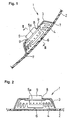
Fig. 1 is a vertical sectional view showing a leg
protection device according to an embodiment of the invention.
Fig. 2 is a sectional view taken along a line II-II of
Fig. 1.
Fig. 3(a) is a vertical sectional view of the leg
protection device when an airbag thereof is inflated, Fig.
3(b) is a view as seen in a direction of arrows B-B of Fig.
3(a), and Fig. 3(c) is a sectional view taken along a line
C-C of Fig. 3(b).
Fig. 4 is a front view an airbag according to another
embodiment.
Fig. 5 is a front view an airbag according to another
embodiment.
Fig. 6 is a front view an airbag according to another
embodiment.
Fig. 7 is a front view an airbag according to another
embodiment.
Fig. 8 is a front view an airbag according to another
embodiment.
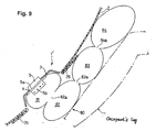
Fig. 9 is a vertical sectional view of an airbag in the
inflated state of a leg protection device according to still
another embodiment.
Figs. 10(a), 10(b) are a front view and a vertical
sectional view of a leg protection device according to further
another embodiment.
Figs. 11(a)-11(c) are illustrations for explaining an
airbag according to an embodiment.
Figs. 12 (a) , 12 (b) are illustrations for explaining an
airbag according to another embodiment.
Fig. 13 is a sectional view showing the airbag of Figs.
12(a), 12(b) in its inflated state.
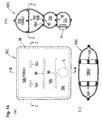
Figs. 14 (a)-14 (c) are illustrations for explaining an
airbag according to still another embodiment.
Figs. 15 (a) , 15 (b) are illustrations for explaining an
airbag according to a further another embodiment.
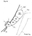
Fig. 16 is an illustration for explaining an airbag
according to another embodiment.
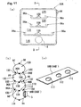
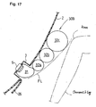
Fig. 17 is an illustration for explaining an airbag
according to yet another embodiment of the invention.
[Embodiments for carrying out the Invention]
Hereinafter, embodiments of the present invention will
be described with reference to the attached drawings. Fig.
1 is a vertical sectional view showing a leg protection device
according to an embodiment, Fig. 2 is a sectional view taken
along a line II-II of Fig. 1, Fig. 3 (a) is a vertical sectional
view of the leg protection device when an airbag thereof is
inflated, Fig. 3(b) is a view as seen in a direction of arrows
B-B of Fig. 3 (a) , and Fig. 3 (c) is a sectional view taken along
a line C-C of Fig. 3(b).
A leg protection device 1 is installed in an interior
panel 2 in front of a front passenger seat of a vehicle. The
interior panel 2 is disposed below an instrument panel. The
leg protection device 1 is arranged substantially at the same
level of the surface of the front passenger seat.
The leg protection device 1 comprises a casing 3 disposed
on a rear surface of the interior panel 2, an airbag 4 folded
and accommodated in the casing 3, and a gas generator 5 for
inflating the airbag 4. The casing 3 is opened at its front
and is disposed such that this open front is covered by the
interior panel 2. The interior panel 2 is provided with tear
lines 6 and hinge lines 7, allowing the interior panel 2 to
be torn along tear lines 6 and to be bent at the hinge lines
7 during the inflation of the airbag 4. Both the tear lines
6 and the hinge lines 7 are composed of grooves formed in the
interior panel 2.
The gas generator 5 has a flange 5a projecting from the
side periphery thereof. The edge around a gas inlet of the
airbag 4 is held or sandwiched between the flange 5a and the
casing 3. The casing 3 has an opening 8 through which the gas
generator 5 is inserted. The flange 5a is fixed to the edge
around the opening 8 by bolts 9. The casing 3 is fixed to a
vehicle member via a bracket, which is not shown.
As shown in Fig. 3(a), in this embodiment, the airbag
4 is composed of a front panel 11 arranged to face an occupant
and a rear panel 12. The rear panel 12 is provided with an
insertion hole (the above-mentioned gas inlet; without
numeral) for gas generator 5 and a vent hole 10 formed therein.
These panels 11, 12 are joined linearly along their
periphery to make them into an envelope shape. Numeral 13
designates a joint line for the joint along their periphery.
A plurality (in this embodiment, six in total) of joint
lines 14 extend from the peripheral joint line 13. Each joint
line 14 is a linear sewn portion rectilinearly extending
substantially in the lateral direction in a state that the
airbag 4 is inflated. The joint lines 14 are continuously
connected at their distal ends to the joint line 13. By the
joint lines 14, eight second chambers 22 are defined inside
the airbag 4.
The joint lines 14 have partitions 15 at the proximal
ends thereof, respectively, to extend vertically, whereby
inlets 22a of the second chambers 22 are narrowed.
The second chambers 22 are arranged in left and right
rows and in four stages in the vertical direction.
Arranged at the center in the lateral direction of the
airbag 4 is a first chamber 21. The first chamber 21 extends
from the upper end to the lower end. The gas generator 5 is
located at the center in the vertical direction of the first
chamber 21.
As the vehicle equipped with the leg protection device
having the aforementioned structure comes into a frontal
collision, the gas generator 5 is actuated to spout out gas
through gas ports 5b so as to initiate the inflation of the
airbag 4.
Gas from the gas generator 5 first flows into the first
chamber 21 so that the first chamber 21 starts to inflate.
Subsequently, the gas in the first chamber 21 flows through
the inlets 22a to inflate the second chambers 22.
According to the initiation of inflation of the airbag
4, the interior panel 2 is pressed by the airbag 4 so as to
be torn along the tear lines 6, forming flaps 25. The flaps
25 are bent at the hinge lines 7. According to the opening
of the flaps 25, the airbag 4 is expanded into a vehicle cabin
and is deployed along the front surface of the interior panel
2.
The inflated airbag 4 receives and stops plunging legs
of the occupant. As the legs plunge into the airbag 4, the
internal pressure of the airbag 4 is increased so that a part
of gas flows out through the vent hole 10, thereby absorbing
impact.
In the leg protection device 1, the inside of the airbag
4 is divided into the first chamber 21 and the second chambers
22. The inflation of the airbag 4 initiates at the first chamber
21. At this point, nearly entire gas pressure is used for
inflating the first chamber 21 so that the first chamber 21
is rapidly inflated. As the first chamber 21 is inflated, gas
is distributed from the first chamber 21 substantially
uniformly into the respective second chambers 22, whereby the
respective second chambers 22 are substantially uniformly
inflated in the lateral direction along the interior panel
2.
Since the joint lines 14 defining the second chambers
22 extend rectilinearly, gas flowed into the second chambers
22 through the inlets 22a flows just straight forward, thereby
rapidly inflating the second chambers 22.
Since the front panel 11 and the rear panel 12 of the
airbag 4 are connected by the joint lines 14 and the partitions
15, the thickness of the airbag 4 is small even when the airbag
4 is fully inflated. Therefore, the airbag 4 can be rapidly
inflated with none or little interference of the occupant's
legs even though the space between the occupant's legs and
the interior panel 2 is small. When the legs plunge into the
inflated airbag 4, the internal pressure of the chamber 21
or 22 into which the legs plunge is increased.
Since the increase in the internal pressure is extreme
as compared to that of the conventional example having an airbag
with a single chamber, the occupant' legs can be sufficiently
received and stopped. Particularly because of the narrowed
inlets 22a of the second chambers 22, the gas in the second
chambers 22 hardly flows back to the first chamber 21.
Accordingly, the impact on the leg received by the second chamber
22 can be absorbed extremely enough.
Fig. 4 through Fig. 9 are front views showing airbags
according to different embodiments, respectively.
An airbag 30 shown in Fig. 4 has a first chamber 31 formed
in a U-like shape extending along the lower edge, the left-and
right-side edges of the airbag. The gas generator 5 is
located at the center of a portion along the lower edge of
the first chamber 31. Second chambers 32 extend in the lateral
direction. Each second chamber 32 has gas inlets 37 at both
lateral sides. Numeral 33 designates a joint line along the
peripheral edge of the panels, 34 designates joint lines as
linear sewn portions for defining the second chambers 32, and
35 designates partitions for narrowing the inlets 37.
An airbag 40 shown in Fig. 5 has a first chamber 41,
extending vertically along the right-side edge of the airbag,
and second chambers 42, communicating with the first chamber
41 through gas inlets 47 which are formed at the right end
sides of the second chambers 42, respectively. The gas generator
5 is located at the center in the vertical direction of the
first chamber 41. Numeral 43 designates a joint line along
the peripheral edge of the panels, 44 designate joint lines
as linear sewn portions for defining the second chambers 42,
and 45 designates partitions for narrowing the gas inlets 47.
An airbag 50 shown in Fig. 6 has a first chamber 51,
extending vertically along the left-side edge of the airbag,
and second chambers 52, communicating with the first chamber
51 through gas inlets 57 which are formed at the left end sides
of the second chambers 52, respectively. The gas generator
5 is located in an upper portion of the first chamber 51. Numeral
53 designates a joint line along the peripheral edge of the
panels, 54 designate joint lines as linear sewn portions for
defining the second chambers 52, and 55 designates partitions
for narrowing the gas inlets 57.
An airbag 60 shown in Fig. 7 has a first chamber 61,
extending along the upper edge, vertically along a middle
portion, and along the lower edge of the airbag. That is, the
first chamber 61 is formed in a sideward H-like shape. Second
chambers 62 are arranged on both sides of the middle portion
(61a) of the first chamber 61 such that each second chamber
62 extends vertically. Third chambers 63 are each formedbetween
the second chamber 62 and right- or left-side edge of the airbag
60. The second chambers 62 communicate with the first chamber
61 (61a) through gas inlets 65. The third chambers 63 communicate
with the second chambers 62 through gas inlets 66, respectively.
The gas generator 5 is located at the center of a portion along
the lower edge of the first chamber 61.
An airbag 70 of Fig. 8 has a first chamber 71 comprising
a portion (71a) extending vertically at the middle and a portion
(71b) extending along lower edge of the airbag. That is, the
first chamber 71 is formed in an inverse T-like shape. The
second chambers 72 are arranged on both side of the portion
71a of the first chamber 71 to extend vertically. The second
chambers 72 communicate with the portion 71b of the first chamber
71 through gas ports 74 which are each formed at the bottom
of each second chamber 72. The gas generator 5 is located at
an upper side of the portion 71a of the first chamber 71.
An airbag 80 of a leg protection device 1' shown in Fig.
9 comprises a first chamber 81, a second chamber 82, a third
chamber 83, and a forth chamber 84. The greater part of the
first chamber 81 stays within the casing 3 even when the airbag
80 is fully deployed. The second chamber 82 expands in front
of the first chamber 81. The third chamber 83 expands above
the second chamber 82, and the fourth chamber 84 expands above
the third chamber 83.
The second, third, and fourth chambers, 82, 83, 84
communicate with the first, second, and third chambers 81,
82, 83 through narrowed gas inlets 82a, 83a, 84a, respectively.
The third and fourth chambers 83, 84 expand along the
interior panel 2. The second, third, fourth chambers 82, 83,
84 extend in the lateral direction in the inflated state. The
number of the gas inlet 82a, 83a, or 84a is one or more.
The other structure of Fig. 9 is the same as that of
Fig. 3(a).
Fig. 10 (a) is a plan view of an airbag according to another
embodiment of the present invention and Fig. 10 (b) is a sectional
view taken along a line B-B of Fig. 10(a).
As shown in Figs. 10 (a), 10 (b) , this airbag 90 comprises
a front panel 92 and a rear panel 94 which are connected to
each other by three partition panels 96. The partition panels
96 are arranged such that they extend substantially parallel
to each other both in the thickness direction and the
vehicle-lateral direction. As shown in Fig. 10(a), the left
and right ends of each partition panel 96 are spaced apart
from the left- and right-side edges of the airbag 90,
respectively. Each partition panel 96 has curved portions 96a,
curved upward in a J-like shape, at the both ends.
In Figs. 10(a), 10(b), numeral 98 designates a joint
line connecting the front panel 92 and the rear panel 94, 100
designates joint lines connecting the front panel 92 and the
partition panels 96, and 102 designates joint lines connecting
the rear panel 94 and the partition panels 96.
In this embodiment, each partition panel 96 comprises
a panel half 96A of which one edge is connected to the front
panel 92 and a panel half 96B of which one edge is connected
to the rear panel 94. The other edges of the panel halves 96A,
96B are connected to each other by sewing yarn 108. Therefore,
the length of the partition panel 96 (this length corresponds
to the distance between the edges, connected to the front panel
92 and the rear panel 94, of the partition panel 96, that is,
the distance between the joint lines 100 and 102. The same
is true for the following. ) can be suitably adj ustedby adjusting
the outlet seam width of the other edges of the panel halves
96A, 96B.
Inside of the airbag 90 is divided into a first chamber
104, formed in a U-like shape extending along the lower edge,
the left-side and right-side edge of the airbag, and three
second chambers 106 which are aligned in the vertical direction
to each extend in parallel with the upper edge of the airbag
90. The gas generator 5 is located about the center of a portion,
extending along the lower edge of the airbag 90, of the first
chamber 104.
As the gas generator 5 is actuated, gas is spouted out
from the gas generator 5 into the first chamber 104. At this
point, nearly entire gas pressure is used for inflating the
first chamber 104 so that the first chamber 104 is rapidly
inflated. The gas in the first chamber 104 flows substantially
uniformly into the second chambers 106, whereby the respective
second chambers 106 are substantially uniformly inflated.
Because the inlets of the second chambers 106 are narrowed
by the curved portions 96a provided on the both ends of the
respective partition panels 96, the gas in the second chambers
106 hardly flow back to the first chambers 104 even when the
occupant's legs plunges into the chamber 106 positioned about
the center of the airbag 90.
According to this airbag 90, since the front panel 92
and the rear panel 94 are connected to each other by the partition
panels 96, the thickness of the airbag is small even when the
airbag 90 is fully inflated. In addition, since the thickness
of the airbag 90 when fully inflated can be adjusted by changing
the length of the partition panels 96, the degree of freedom
in design is extremely high.
Since the front panel 92 and the rear panel 94 are
connected to each other by the partition panels 96, stresses,
applied to connected portions between the panels 92, 94 and
the partition panels 96 when the inner pressure of the airbag
90 is increased, are smaller than those in case of the panels
92 and 94 are connected to each other directly by sewing or
the like. Therefore, the panels 92, 94 may be made of material
of which strength is relatively low, thus making the
manufacturing cost of the airbag 90 relatively low.
Though three partition panels 96 are used for connecting
the front panel 92 and the rear panel 94 in the embodiment
of Figs. 10 (a) , 10 (b) , the number of the partition panels may
be one, two, or four or more. The configuration of the partition
panel is arbitrarily designed. Besides the plane type shown
in Figs. 10 (a), 10 (b) , for example, band-like partition panels
may be used.
As an airbag 90A shown in Figs. 11(a)-11(c), the partition
panels may be provided with vent holes (gas holes) so that
the communication of gas between adjacent chambers in the airbag
is allowed by the vent holes. Hereinafter, this airbag 90A
will be described in detail. Fig. 11(a) is a front view of
the airbag 90A and Fig. 11 (b) is a sectional view taken along
a line B-B of Fig. 11(a). Fig. 11(c) is a perspective view
showing of a panel half of a partition panel which is formed
with vent holes.
Similarly to the airbag 90 of Figs. 10(a), 10(b), in
the airbag 90A, the front panel 92 and the rear panel 94 are
connected to each other by three partition panels 96 which
are arranged to extend parallel to each other in the thickness
direction and the lateral direction of the airbag 90A and
arranged in lateral rows aligned in the vertical direction
of the airbag 90A in a state that the airbag 90A is inflated.
In this embodiment, as shown in Figs. 11(b), 11(c), a
panel half 96B (96B') of the lowest partition panel 96 (96')
among the three partitions 96 is formed with a plurality of
small vent holes 112. As shown in Fig. 11(a), the left and
right ends of the lowest partition panel 96 (96') are located
nearer to the left- and right-side edges than the left and
right ends of the other two partition panels 96 so that the
lowest partition panel 96 (96') has curved portions 96a at
positions near the left- and right-side edges of the airbag
90A.
In this embodiment, when the airbag 90A is inflated,
the distances between the left and right ends of the partition
panel 96 (96') and the left- and right-side edges of the airbag
90A, respectively are shortened to nearly close the path of
gas because the left- and right-side edges of the airbag 90A
move close to each other according to the increase in the
thickness of the airbag 90A. However, the airbag may be designed
such that the spaces therebetween are left even when the airbag
90A is inflated.
The inside of the airbag 90A is divided by these partition
panels 96 into a first chamber 116 extending along the lower
edge of the airbag 90A in the lateral direction, a second chamber
118 formed in a U-like shape extending along the upper edge
of the first chamber 116 and the left- and right-side edges
of the airbag 90A, and two third chambers 120 extend along
the upper edge of the airbag 90A in the lateral direction and
arranged vertically in parallel to each other. The gas generator
5 is located about the center of the first chamber 116 extending
along the lower edge of the airbag 90A.
The other structure of the airbag 90A is the same as
that of the airbag 90 of Figs. 10 (a) , 10 (b) . Therefore, component
parts of Figs. 11 (a) -11 (c) corresponding to the parts of the
embodiment of Figs. 10 (a), 10 (b) are designated with the same
reference numeral, thus omitting the detail description of
such component parts.
As the gas generator 5 is actuated, gas is spouted out
from the gas generator 5 into the first chamber 116. At this
point, nearly entire gas pressure is used for inflating the
first chamber 116 so that the first chamber 116 is rapidly
inflated. The gas in the first chamber 116 flows into the second
chamber 118 through the vent holes 112 formed in the partition
panel 96 (96')and the both sides of the partition panel 96
(96'), whereby the second chamber 118 is inflated. As noted
above in this embodiment, as the airbag 90A is inflated, the
spaces between the left and light ends of the partition panel
96 (96') and the left- and right-side edges of the airbag 90A
are nearly closed. Therefore, most of gas from the first chamber
116 to the second chamber 118 flows through the vent holes
112 and only a little part of the gas flows through the spaces
at both sides of the partition panel 96 (96'). The gas in the
second chamber 118 successively flows into the third chambers
120, 120 to inflate the chambers 120, 120.
In this embodiment, as the airbag 90A is inflated, the
spaces between the lateral ends of the lowest partition panel
96 (96') and the left- and right-side edges of the airbag 90A
are nearly closed. As a result, the amount of gas flowing from
the first chamber 116 to the second chamber 118 through the
spaces at the both sides of the partition panel 96 (96') is
so little. Therefore, gas is easily accumulated at both side
edges of the first chamber 116 so that the first chamber 116
can be rapidly inf lated to every corner . Forthis, high-pressure
and high-speed gas starts to flow into the second chamber through
the vent holes 112 at a relatively earlier stage. In addition,
the gas in the second chamber flows into the third chamber
at a relatively earlier stage. As a result of this, the
respective chambers 116-120 are inflated without large time
difference so that the airbag 90A can be inflated significantly
smooth as a whole.
Though only one panel half of the lowest partition panel
among the partition panels is formed with vent holes in this
embodiment, the other panel half may also be formed with vent
holes. In addition, any partition panel may have vent holes
and all of the partition panels may be formed with vent holes.
Though a plurality of small holes are formed as the vent holes
in this embodiment as shown in Fig. 11 (c) , the configuration,
the size, and the number of the vent holes are not limited
thereto. The behavior of the airbag during inflation can be
controlled by suitably changing of adjusting the configuration,
the size, and the number of the vent holes corresponding to
the construction of the airbag.
Referring to Figs. 12(a)-15(b), an embodiment of which
a chamber for receiving knees is designed to have thickness
larger than that of other chambers when the airbag is inflated.
Figs. 12(a), 12 (b) and Fig. 13 show a first example of
the aforementioned airbag. Fig. 12 (a) is a front view of the
airbag, Fig. 12 (b) is a sectional view taken along a line B-B
of Fig. 12 (a) , and Fig. 13 is a vertical sectional view showing
a state that the airbag is inflated and deployed along an
interior panel.
This airbag 90B has a similar structure as that of the
aforementioned airbag 90 shown in Figs. 10(a), 10(b). That
is, the airbag 90B has a front panel 92 and a rear panel 94
which are connected to each other by three partition panels
96 similarly to the airbag 90. The partition panels 96 are
arranged such that these extend substantially parallel to each
other both in the thickness direction of the airbag 90B and
the vehicle-lateral direction when the airbag 90B is inflated.
Difference from the aforementioned airbag 90 is that each
partitionpanel 96 extends in the lateral direction in a straight
line.
The distance between the uppermost partition panel 96
among the three partition panels 96 and the upper edge of the
airbag 90B is larger than the distance between the other
partition panels and the distance between the lowest partition
and the lower edge of the airbag 90B. Therefore, the uppermost
second chamber 106 (106U) has a thickness larger than that
of the other second chambers 106 and that of the first chamber
104 when inflated. The second chamber 106U is positioned at
the top of the airbag 90B.
The other structure of the airbag 90B is the same as
that of the airbag 90 and the same numerals designate the
corresponding parts.
As the gas generator 5 is actuated, gas is spouted out
from the gas generator 5 into the first chamber 104. At this
point, nearly entire gas pressure is used for inflating the
first chamber 104 so that the first chamber 104 is rapidly
inflated. Successively, the gas in the first chamber 104 flows
substantially uniformly into the second chambers 106, whereby
the respective second chambers 106 are substantially uniformly
inflated.
According to this airbag 90B, the uppermost second
chamber 106U is inflated and deployed in a range about and
above a portion in front of and corresponding to a seat squab
surface of the vehicle seat. Accordingly, the uppermost second
chamber 106U can be inflated and deployed about a portion in
front of the knees of the occupant, thereby receiving the knees
and enough absorbing the impact on the knees and the joints
for thighs.
In this embodiment, as an airbag 90B' shown in Fig. 16,
the airbag may be designed to have thickness gradually
increasing from the bottom to the top when inflated by selecting
the lengths and positions of the partition panels. It should
be noted that a line FL of Fig. 16 schematically indicates
an envelope of a face, opposing the occupant, of the airbag
90B'. The distance between the envelope FL and the interior
panel 2 increases upwardly.
Though three partition panels 96 are used for connecting
the front panel 92 and the rear panel 94 in the embodiments
of Figs. 12(a), 12(b), Fig. 13, and Fig. 16, the number of
the partition panels may be one, two, or four or more.
As an airbag 90C shown in Figs. 14(a)-14(c), tethers
(belts) 140 may be provided in the uppermost second chamber
106U for connecting the front panel 92 and the rear panel 94.
Fig. 14 (a) is a front view of the airbag 90C, Figs. 14 (b) and
14(c) are sectional views taken along a line B-B and a line
C-C of Fig. 14(a), respectively.
Because of the tethers 140, the thickness of the uppermost
second chamber 106U when inflated can be prevented from being
too large. Though two tethers 140 are used in Figs. 14(a),
14 (b) , and 14 (c) , one or more than three tethers may be used.
Figs. 15(a), 15 (b) show an airbag 30A which is similar
to the aforementioned airbag 30 of Fig. 4 but is different
in that the uppermost second chamber 32 (32U) has thickness
larger than that of the other second chambers 32 and that of
a first chamber 31 when inflated. Fig. 15(a) is a front view
of the airbag 30A and Fig. 15(b) is a sectional view taken
along a line B-B of Fig. 15(a).
The airbag 30A comprises a front panel 11 arranged to
face the occupant and a rear panel 12 arranged behind. The
rear panel 12 is provided with an insertion hole (without
numeral) for a gas generator 5.
These panels 11, 12 are joined linearly along their
periphery to make them into an envelope shape. Numeral 33
designates a joint line for the joint along their periphery.
Similarly to the airbag 30 of Fig. 4, this airbag 30A
has a first chamber 31 formed in a U-like shape extending along
the lower edge, left- and right-side edges of the airbag. The
gas generator 5 is located at the center of a portion along
the lower edge of the first chamber 31. Second chambers 32
extend in the lateral direction. Each second chamber 32 has
gas inlets 37 at both lateral sides. Numeral 34 designates
joint lines as linear sewn portions for defining the second
chambers 32, and 35 designates partitions for narrowing the
inlets 37. It should be noted that the partitions 35 may be
omitted.
The airbag 30A is provided with a plurality of second
chambers 32. Among them, the uppermost second chamber 32 is
located at the top of the airbag 30A. The distance between
the joint line 34 and the top edge of the airbag 30A is larger
than the distance between the adjacent joint lines 34 and larger
than the distance between the joint line 34 and the lower edge
of the airbag 30A. Therefore, the uppermost second chamber
32U has a thickness larger than that of the other second chambers
32 and that of the first chamber 31 when inflated.
According to this airbag 30A, the uppermost second
chamber 32U is inflated and deployed about a portion in front
of the knees of the occupant, thereby receiving the knees.
Also in this embodiment, as an airbag 30B shown in Fig.
17, the airbag may be designed to have thickness gradually
increasing from the bottom to the top when inflated so that
the distance between the envelope FL and the interior panel
2 increases toward the top.
Though the leg protection device is installed to the
interior panel 2 in any of the aforementioned embodiments,
the device may be installed to a glove box. The joint along
joint lines may be formed by adhesive or a combination of sewing
yarns and adhesive, besides only by sewing yarns.
[Effects of the Invention]
As described above, a leg protection device for vehicle
occupants of the present invention has an airbag of which
thickness when inflated is small, whereby the airbag can be
rapidly inflated even with a gas generator having small
generating capacity. The leg protection device can
sufficiently receive and stop occupant's legs even with an
airbag having a small thickness when inflated.