EP1466759A1 - Heavy duty tire - Google Patents
Heavy duty tire Download PDFInfo
- Publication number
- EP1466759A1 EP1466759A1 EP02793351A EP02793351A EP1466759A1 EP 1466759 A1 EP1466759 A1 EP 1466759A1 EP 02793351 A EP02793351 A EP 02793351A EP 02793351 A EP02793351 A EP 02793351A EP 1466759 A1 EP1466759 A1 EP 1466759A1
- Authority
- EP
- European Patent Office
- Prior art keywords
- ground
- tire
- tread
- total sum
- contact force
- Prior art date
- Legal status (The legal status is an assumption and is not a legal conclusion. Google has not performed a legal analysis and makes no representation as to the accuracy of the status listed.)
- Granted
Links
Images




Classifications
-
- B—PERFORMING OPERATIONS; TRANSPORTING
- B60—VEHICLES IN GENERAL
- B60C—VEHICLE TYRES; TYRE INFLATION; TYRE CHANGING; CONNECTING VALVES TO INFLATABLE ELASTIC BODIES IN GENERAL; DEVICES OR ARRANGEMENTS RELATED TO TYRES
- B60C11/00—Tyre tread bands; Tread patterns; Anti-skid inserts
- B60C11/03—Tread patterns
- B60C11/0327—Tread patterns characterised by special properties of the tread pattern
- B60C11/0332—Tread patterns characterised by special properties of the tread pattern by the footprint-ground contacting area of the tyre tread
-
- B—PERFORMING OPERATIONS; TRANSPORTING
- B60—VEHICLES IN GENERAL
- B60C—VEHICLE TYRES; TYRE INFLATION; TYRE CHANGING; CONNECTING VALVES TO INFLATABLE ELASTIC BODIES IN GENERAL; DEVICES OR ARRANGEMENTS RELATED TO TYRES
- B60C11/00—Tyre tread bands; Tread patterns; Anti-skid inserts
-
- B—PERFORMING OPERATIONS; TRANSPORTING
- B60—VEHICLES IN GENERAL
- B60C—VEHICLE TYRES; TYRE INFLATION; TYRE CHANGING; CONNECTING VALVES TO INFLATABLE ELASTIC BODIES IN GENERAL; DEVICES OR ARRANGEMENTS RELATED TO TYRES
- B60C11/00—Tyre tread bands; Tread patterns; Anti-skid inserts
- B60C11/03—Tread patterns
- B60C11/0306—Patterns comprising block rows or discontinuous ribs
-
- B—PERFORMING OPERATIONS; TRANSPORTING
- B60—VEHICLES IN GENERAL
- B60C—VEHICLE TYRES; TYRE INFLATION; TYRE CHANGING; CONNECTING VALVES TO INFLATABLE ELASTIC BODIES IN GENERAL; DEVICES OR ARRANGEMENTS RELATED TO TYRES
- B60C11/00—Tyre tread bands; Tread patterns; Anti-skid inserts
- B60C11/03—Tread patterns
- B60C11/04—Tread patterns in which the raised area of the pattern consists only of continuous circumferential ribs, e.g. zig-zag
-
- B—PERFORMING OPERATIONS; TRANSPORTING
- B60—VEHICLES IN GENERAL
- B60C—VEHICLE TYRES; TYRE INFLATION; TYRE CHANGING; CONNECTING VALVES TO INFLATABLE ELASTIC BODIES IN GENERAL; DEVICES OR ARRANGEMENTS RELATED TO TYRES
- B60C11/00—Tyre tread bands; Tread patterns; Anti-skid inserts
- B60C11/03—Tread patterns
- B60C2011/0337—Tread patterns characterised by particular design features of the pattern
- B60C2011/0386—Continuous ribs
- B60C2011/0388—Continuous ribs provided at the equatorial plane
-
- Y—GENERAL TAGGING OF NEW TECHNOLOGICAL DEVELOPMENTS; GENERAL TAGGING OF CROSS-SECTIONAL TECHNOLOGIES SPANNING OVER SEVERAL SECTIONS OF THE IPC; TECHNICAL SUBJECTS COVERED BY FORMER USPC CROSS-REFERENCE ART COLLECTIONS [XRACs] AND DIGESTS
- Y10—TECHNICAL SUBJECTS COVERED BY FORMER USPC
- Y10T—TECHNICAL SUBJECTS COVERED BY FORMER US CLASSIFICATION
- Y10T152/00—Resilient tires and wheels
- Y10T152/10—Tires, resilient
- Y10T152/10495—Pneumatic tire or inner tube
- Y10T152/10765—Characterized by belt or breaker structure
Definitions
- the present invention relates to a heavy duty tire for suppressing uneven wear and equalizing wear by specifying a distribution of a total sum of ground-contact force.
- tread profile shape (a) is formed into a single arc shape in a vulcanization die as schematically shown in Fig. 7.
- a tread ground-contact edge portion (so-called tread shoulder portion) is formed of a flat arc having a great radius of curvature as compared with a tire equator portion (so-called tread center portion), and a ground-contact length in a ground-contact surface shape of the tread shoulder portion is elongated.
- the present inventor focused attention on a relation between the ground-contact force and the uneven wear and studied the relation. As a result, the inventor found that a correlation between the ground-contact force and wear energy was strong, and if the distribution of the ground-contact force was specified, it was possible to suppress the uneven wear including the unbalanced wear and to equalize the wear without excessively increasing the rubber gauge thickness.
- the present invention is characterized in that when a normal load is applied to a tire in its normal ground-contact state in which a regular rim is assembled into the tire and a regular internal pressure is charged into the tire, in a total sum of ground-contact force applied to a tire equator side half region and a ground-contact edge side half region, each of which being a rib-like land portion, a ratio of a total sum of the ground-contact force between the axially adjacent half regions is limited to the following predetermined ranges.
- a first invention is characterized in that a ratio P2c/P1a between a total sum P1a of ground-contact force applied to a half region R1a obtained by dividing an inner rib-like land portion R1 by the tire equator and a total sum P2c of ground-contact force applied to a tire equator side half region R2c in the intermediate rib-like land portion R2 is set in a range of 0.9 to 1.05, a ratio P2e/P2c between the total sum P2c of the ground-contact force and a total sum P2e of ground-contact force applied to a ground-contact edge side half region R2e in the intermediate rib-like land portion R2 is set in a
- a second invention is characterized in that a ratio P1e/P1c between a total sum P1c of ground-contact force applied to a tire equator-side half region J1c in the inner rib-like land portion J1 and a total sum P1e of ground-contact force applied to a ground-contact edge-side half region J1e is set in a range of 0.8 to 1.0, a ratio P2c/P1e between the total sum P1e of the ground-contact force and a total sum P2c of ground-contact force applied to a tire equator side half region J2c in the outer rib-like land portion J2 is set in a range of 0.8 to 1.0, and a ratio P2e/P2c between the total
- the "regular rim” is a rim determined for each tire according to a standard on which the tire is based among standards for tires, and for example,
- the "regular internal pressure” means an air pressure determined for each tire according to a standard on which the tire of the present invention is based among standards for tires.
- the regular internal pressure means a maximum air pressure in the case of JATMA
- the regular internal pressure means a maximum value described in "TIRE LOAD LIMITS AT VARIOUS COLD INFLATION PRESSURES" in the case of TRA
- the regular internal pressure means a "INFLATION PRESSURE" in the case of ETRTO, but when the tire is for a passenger vehicle, the regular internal pressure is 180kPa.
- the "normal load” means a load determined for each tire according to a standard on which the tire of the present invention is based among standards for tires.
- the normal load is a maximum load capacity in the case of the JATMA, and the normal load means a maximum value described in the Table "TIRE LOAD LIMITS AT VARIOUS COLD INFLATION PRESSURES" in the case of TRA, and the normal load means "LOAD CAPACITY" in the case of ETRTO.
- the "ground-contact edge” is an outer edge in the tire axial direction of the tread ground-contact surface which comes into contact with the ground when the normal load is applied to the tire in the regular internal pressure state in which the normal rim is assembled to the tire and the regular internal pressure is charged into the tire.
- a distance between the outer edge (ground-contact edge) and the tire equator is called half of the ground-contact width of the tread.
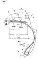
- Fig. 1 is a sectional view of a heavy duty tire of the invention for a truck, a bus and the like.
- a heavy duty tire 1 comprises a carcass 6 extending from a tread portion 2 to a bead core 5 of a bead portion 4 through a sidewall portion 3, and a belt layer 7 disposed inside the tread portion 2 and outside the carcass 6.
- the carcass 6 comprises one or more (one, in this example) carcass ply 6A in which a carcass cord is arranged at an angle of 70 to 90° with respect to a circumferential direction of the tire.
- a metal cord such as steel is used as the carcass cord.
- the carcass ply 6A has a ply body 6a extending between the bead cores 5 and 5.
- the ply body 6a is provided at its opposite sides with turnup portions 6b which are secured after being turned up from inner side toward outer side around the bead core 5.
- a bead apex rubber 8 extending radially outward from the bead core 5 is disposed between the ply body 6a and the turnup portion 6b.
- the bead apex rubber 8 reinforces a portion of the tire from the bead portion 4 to the sidewall portion 3.
- the belt layer 7 comprises three or more belt plies using metal cords as belt cords.
- the belt layer 7 comprises four belt plies, i.e., a first belt ply 7A in which a steel cord is arranged radially innermost side at an angle of 60 ⁇ 15° for example with respect to the circumferential direction of the tire, and second to fourth belt plies 7B, 7C and 7D in which steel cords are arranged at a small angle of 10 to 35° for example with respect to the circumferential direction of the tire.
- a ply width of the first belt ply 7A in the axial direction of the tire is smaller than a ply width of the second belt ply 7B and is substantially equal to a ply width of the third belt ply 7C.
- a ply width WB of the second belt ply 7B having the greatest width is 0.80 to 0.95 times a tread ground-contact width WT, thereby reinforcing substantially the entire width of the tread portion 2 while providing a hoop effect and enhancing the rigidity of the tread.
- the fourth belt ply 7D having the narrowest width functions as a breaker which protects the first to third belt plies 7A to 7D and the carcass 6 from damage.
- the tread portion 2 of the heavy duty tire 1 of the first invention comprises four longitudinal main grooves G, i.e., inner longitudinal main grooves G1 extending on opposite sides of the tire equator C and outer longitudinal main grooves G2 extending outer sides of the longitudinal main grooves G1.
- a tread surface is divided into five rib-like land portions R, i.e., a rib-like land portion R1 located at an inner side on the tire equator C, rib-like land portions R3 located at outer sides of the ground-contact edge E, and rib-like land portions R2 located between the rib-like land portions R1 and R3.
- the rib-like land portions R may be block rows or a rib.
- Each of the longitudinal main grooves G1 and G2 has a groove width of 3mm or more.
- the longitudinal main groove G is straight or zigzag (including corrugate) in shape and extends in the circumferential direction. It is preferable that the groove width of each of the longitudinal main grooves G1 and G2 is 5mm or more, and more preferably in a range of 7 to 10mm. It is preferable that a groove depth is 9mm or more, and more preferably in a range of 14.5 to 17.5mm.
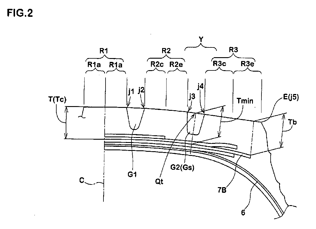
- a groove center line N of the outer longitudinal main groove G2 i.e., the shoulder groove Gs located at the outermost side in the axial direction of the tire, passes through a region Y which is separated from the tire equator C by a distance of 0.5 to 0.7 times the half of the ground-contact width of the tread WT/2.
- the tread portion 2 is divided into a tread center portion Yc located on an inner side of the shoulder groove Gs and a tread shoulder portion Ys located on an outer side of the shoulder groove Gs.
- the inner and intermediate rib-like land portions R1 and R2 are disposed in the tread center portion Yc, and the outer rib-like land portion R3 is disposed in the tread shoulder portion Ys.
- a normal rim is assembled to the tire 1 and a regular internal pressure is charged into the tire.
- a normal load is applied to the tire in the regular internal pressure state and the tire is brought into a normal ground-contact state.
- the ground-contact force in this state is specified as follows:
- Each total sum P1a, P2c, P2e, P3c and P3e of the ground-contact force can be obtained in the following manner. That is, the tire 1 to which the normal load is applied is brought into contact with a sheet body on which a large number of sensors are spread, and a load applied to each the sensor is measured. Outputs of the sensors with which the half regions contacted are summed for every half region, and it is possible to obtain the total sum of the ground-contact force applied to the half regions R1a to R3e.
- the present inventor found that the total sum of the ground-contact force has a strong correlation with respect to the wear energy, and if the total sum P1a to P3e of the ground-contact force applied to the half regions R1a to R3e fall within the ranges 1) to 4), the uneven wear including the unbalanced wear could be suppressed and the wear could be equalized.
- the ratio P3e/P1a between the total sum P1a of the ground-contact force and the total sum P3e of the ground-contact force is set in a range of 0.75 to 1.0.
- the tread thickness T is gradually increased from the smallest tread thickness position Qt axially inward of the tire to the tread thickness Tc, and axially outward of the tire to the tread thickness Tb.
- the tread thickness Tb becomes equal to or less than 1.10 ⁇ Tc, increase in the rubber gauge thickness in the tread shoulder portion Ys can be suppressed, the separation of the end of the belt by the heat of rubber can be prevented, and high endurance can also be ensured.
- the second belt ply 7B is formed of a single arc whose center is on the tire equator C
- the tread profile line S in the tread center portion Yc is formed of a projecting arc profile line S1 using a single arc or a plurality of arcs
- the tread profile line S in the tread shoulder portion Ye is formed of a substantially straight profile line S2.
- the tread portion 2 of the heavy duty tire 1 of the second invention comprises three longitudinal main grooves G, i.e., a central longitudinal main groove G1 extending on the tire equator C, and two outer longitudinal main grooves G2 extending on each side of the longitudinal main groove G1.
- the tread surface is divided into four rib-like land portions J, i.e., inner rib-like land portions J1 on each side of the tire equator C, and outside rib-like land portions J2 on the ground-contact edge E side.
- the rib-like land portions J may be block rows or a rib, like the rib-like land portions R.
- the shoulder groove Gs which is the outer longitudinal main groove G2 is formed in the region Y.
- the ground-contact length in the normal ground-contact state is specified as follows:
- the ratio P1e/P1c is limited to 0.8 to 1.0 as shown in 1), uneven wear on the ground-contact edge side in the inner rib-like land portion J1 can be suppressed. If the ratio P2e/P2c is limited to 0.6 to 1.0 as shown in 3), uneven wear on the ground-contact edge side in the outer rib-like land portion J2 can be suppressed. If the ratio P2c/P1e is limited to 0.8 to 1.0 as shown in 2), uneven wear on the tire equator side of the outer rib-like land portion J2 with respect to the inner rib-like land portion J1 can be suppressed.
- ratio P1e/P1c, ratio P2e/P2c and ratio P2c/P1e are out of the above ranges, balance of wear energies of the half regions J1c to J2e is lost, and uneven wear is generated.
- the ratio P2e/P2c is set to 0.7 or higher.
- the ratio P2e/P1c between the total sum P1c of the ground-contact force and the total sum P2e of the ground-contact force is set in a range of 0.4 to 0.9.
- the tread thickness Tb becomes equal to or less than 1.03 ⁇ Tc, increase in the rubber gauge thickness in the tread shoulder portion Ys can be suppressed, the separation of the end of the belt by the heat of rubber can be prevented, and high endurance can also be ensured.
- the second belt ply 7B is formed of a single arc whose center is on the tire equator C
- the tread profile line S in the tread center portion Yc is formed of a projecting arc profile line S1 using a single arc or a plurality of arcs
- the tread profile line S in the tread shoulder portion Ye is formed of a substantially straight profile line S2.
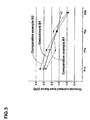
- Fig. 4 is a diagram showing a distribution of the total sum of the ground-contact force applied to each the half region.
- the wear amount are indicated while a comparative example 1 is defined as 100. The smaller the value, the smaller the wear amount is.
- Fig. 5 is a diagram showing a distribution of the total sum of the ground-contact force applied to each half region in the embodiment B1 and the comparative examples B1 and B2.
- Rims (22.5 ⁇ 7.50) were assembled to the tread portion, internal pressure (800kPa) was charged into the tires, and tires were mounted to front wheels of a truck (2-2 ⁇ D type), the truck was allowed to run through a distance of 10,000km. In the tires after running,
- the heavy duty tire of the present invention has the above-described structure, it is possible to suppress the uneven wear including the unbalanced wear and to equalize the wear without excessively increasing the rubber gauge thickness.
Landscapes
- Engineering & Computer Science (AREA)
- Mechanical Engineering (AREA)
- Tires In General (AREA)
Abstract
Description
when a normal load is applied to a tire in its normal ground-contact state in which a regular rim is assembled into the tire and a regular internal pressure is charged into the tire, in a total sum of ground-contact force applied to a tire equator side half region and a ground-contact edge side half region, each of which being a rib-like land portion, a ratio of a total sum of the ground-contact force between the axially adjacent half regions is limited to the following predetermined ranges.
a ratio P2c/P1a between a total sum P1a of ground-contact force applied to a half region R1a obtained by dividing an inner rib-like land portion R1 by the tire equator and a total sum P2c of ground-contact force applied to a tire equator side half region R2c in the intermediate rib-like land portion R2 is set in a range of 0.9 to 1.05,
a ratio P2e/P2c between the total sum P2c of the ground-contact force and a total sum P2e of ground-contact force applied to a ground-contact edge side half region R2e in the intermediate rib-like land portion R2 is set in a range of 0.75 to 1.0,
a ratio P3c/P2e between the total sum P2e of the ground-contact force and a total sum P3c of ground-contact force applied to a tire equator side half region R3c in the outer rib-like land portion R3 is set in a range of 0.9 to 1.2, and
a ratio P3e/P3c between the total sum P3c of the ground-contact force and a total sum P3e of ground-contact force applied to a ground-contact edge side half region R3e in the outer rib-like land portion R3 is set in a range of 0.8 to 1.1.
a ratio P1e/P1c between a total sum P1c of ground-contact force applied to a tire equator-side half region J1c in the inner rib-like land portion J1 and a total sum P1e of ground-contact force applied to a ground-contact edge-side half region J1e is set in a range of 0.8 to 1.0,
a ratio P2c/P1e between the total sum P1e of the ground-contact force and a total sum P2c of ground-contact force applied to a tire equator side half region J2c in the outer rib-like land portion J2 is set in a range of 0.8 to 1.0, and
a ratio P2e/P2c between the total sum P2c of the ground-contact force and a total sum P2e of ground-contact force applied to a ground-contact edge side half region J2e in the outer rib-like land portion J2 is set in a range of 0.6 to 1.0.
- in JATMA, when a narrower rim width than the standard rim is set, the regular rim for the tire is a "rim having a rim width which is narrower than the standard rim by one rank", and when no narrower rim width than the standard rim is set, the regular rim for the tire is a "standard rim",
- in TRA, when a narrower rim width than the "Design Rim" is set, the regular rim for the tire is a "rim having narrower width than the "Design Rim" by one rank", and when no narrower rim width than the "Design Rim" is set, the regular rim for the tire is the "Design Rim", and
- in ETRTO, when a rim width narrower than the "Measuring Rim" is set, the regular rim for the tire is a "rim having narrower width than the "Measuring Rim" by one rank", and when no narrower rim than the "Measuring Rim" is set, the regular rim for the tire is the "Measuring Rim".
- a smallest tread thickness position Qt where the tread thickness T becomes a minimum value Tmin is provided in the region Y,
- the minimum value Tmin is set to 0.89 to 0.97 times the tread thickness Tc at the tire equator C, and
- a tread thickness Tb of the
second belt ply 7B at the outer end position is set to 0.95 to 1.10 times the tread thickness Tc.
- a tread thickness Ty in each position in the region Y is set in a range of 0.91 to 1.05 times the tread thickness Tc at the position of the tire equator C, and
- a tread thickness Tb at the position of the outer end of the second belt ply is set in a range of 0.98 to 1.03 times the tread thickness Tc.
- a side edge position j1 in the ground-contact edge-side of the inner rib-like land portion R1,
- a side edge position j2 in the tire equator-side of the intermediate rib-like land portion R2,
- a side edge position j3 in the ground-contact edge-side of the intermediate rib-like land portion R2,
- a side edge position j4 in the tire equator-side of the outer rib-like land portion R3, and
- a side edge position j5 in the ground-contact edge-side of the outer rib-like land portion R3 (corresponding to the ground-contact edge E).
| Embodiment A1 | Embodiment A2 | Embodiment A3 | Embodiment A4 | Comparative example A1 | Comparative example A2 | Comparative example A3 | |
| Tread ground-contact width WT <mm> | 240 | 240 | 240 | 240 | 240 | 240 | 240 |
| Width WB of belt ply (mm) | 220 | 220 | 220 | 220 | 220 | 220 | 220 |
| Ground-contact force (KN) | |||||||
| ·P1a | 3.14 | 3.43 | 3.30 | 3.33 | 3.45 | 3.11 | 3.45 |
| ·P2c | 3.22 | 3.19 | 3.22 | 3.10 | 3.38 | 3.06 | 3.25 |
| ·P2e | 2.94 | 2.87 | 2.71 | 2.79 | 3.21 | 2.90 | 2.37 |
| ·P3c | 3.24 | 2.93 | 3.03 | 2.94 | 2.89 | 2.90 | 2.96 |
| ·P3e | 2.7 | 2.81 | 2.98 | 3.08 | 2.31 | 3.27 | 3.20 |
| ·Total | 15.24 | 15.24 | 15.24 | 15.24 | 15.24 | 15.24 | 15.24 |
| Ratio of ground-contact force | |||||||
| ·P2c/P1a | 1.03 | 0.93 | 0.98 | 0.93 | 0.98 | 0.98 | 0.94 |
| · P2e/P2c | 0.91 | 0.90 | 0.84 | 0.90 | 0.95 | 0.95 | 0.73 |
| · P3c/P2e | 1.10 | 1.02 | 1.12 | 1.05 | 0.90 | 1.00 | 1.25 |
| · P3e/P3c | 0.83 | 0.96 | 0.98 | 1.05 | 0.80 | 1.13 | 1.08 |
| · P3e/P1a | 0.86 | 0.82 | 0.90 | 0.93 | 0.67 | 1.05 | 0.93 |
| Tread thickness T <mm> | |||||||
| · Tmin | 22.75 | 23.5 | 23.5 | 23.5 | 25 | 23.5 | 22.0 |
| · Tc | 25 | 25 | 25 | 25 | 25 | 25 | 25 |
| · Tb | 25 | 24.25 | 25.25 | 26.75 | 25 | 28.75 | 25 |
| (Ratio Tmin/Tc) | 0.91 | 94 | 0.94 | 0.94 | 1 | 0.94 | 0.88 |
| (Ratio Tb/Tc) | 1 | 0.97 | 1.01 | 1.07 | 1 | 1.15 | 1 |
| Wear | |||||||
| Wear amount (position j1) | 100 | 100 | 100 | 100 | 100 | 100 | 105 |
| Wear amount (position j2) | 100 | 99 | 100 | 100 | 100 | 105 | 110 |
| Wear amount (position j3) | 100 | 98 | 99 | 100 | 100 | 105 | 95 |
| Wear amount (position j4) | 95 | 96 | 96 | 95 | 100 | 100 | 95 |
| Wear amount (position j5) | 87 | 90 | 85 | 80 | 100 | 90 | 95 |
| Embodiment B1 | Embodiment B2 | Comparative example B1 | Comparative example B2 | |
| Tread ground-contact width WT <mm> | 225 | 225 | 201 | 225 |
| Width WB of belt ply <mm> | 200 | 200 | 192 | 188 |
| Ratio of ground-contact force | ||||
| ·P1e/P1c | 0.844 | 0.868 | 0.743 | 0.859 |
| · P2e/P2c | 0.789 | 0.697 | 0.557 | 0.559 |
| · P2c/P1c | 0.801 | 0.809 | 1.060 | 0.720 |
| Tread thickness T | ||||
| Ty | 25 | 26.1 | 26.33 | 26.95 |
| Tc | 25 | 25 | 25 | 25 |
| Tb | 25.73 | 25.55 | 26.85 | 26.73 |
| (Ratio Ty/Tc) | 1.000 | 1.044 | 1.053 | 1.078 |
| (Ratio Tb/Tc) | 1.029 | 1.022 | 1.074 | 1.069 |
| Wear | ||||
| · Ratio Z1/Z2 | 1.15 | 1.44 | 1.19 | 1.05 |
| · Z3 | 0.0 | 0.0 | 2.0 | 0.5 |
| · Z4 | 1.5 | 2.0 | 5.0 | 3.5 |
Claims (6)
- A heavy duty tire comprising a carcass extending from a tread portion to a bead core of a bead portion through a sidewall portion, and a belt layer disposed inside the tread portion and outside the carcass, wherein
the tread portion is divided by four longitudinal main grooves extending in a circumferential direction of the tire into an inner rib-like land portion R1 on a tire equator, outer rib-like land portions R3 in a ground-contact edge-side, and intermediate rib-like land portions R2,
in a normal ground-contact state in which the tire is mounted on the regular rim, a regular internal pressure is charged into the tire and a normal load is applied to the tire,
a ratio P2c/P1a between a total sum P1a of ground-contact force applied to a half region R1a obtained by dividing an inner rib-like land portion R1 by the tire equator and a total sum P2c of ground-contact force applied to a tire equator side half region R2c in the intermediate rib-like land portion R2 is set in a range of 0.9 to 1.05,
a ratio P2e/P2c between the total sum P2c of the ground-contact force and a total sum P2e of ground-contact force applied to a ground-contact edge side half region R2e in the intermediate rib-like land portion R2 is set in a range of 0.75 to 1.0,
a ratio P3c/P2e between the total sum P2e of the ground-contact force and a total sum P3c of ground-contact force applied to a tire equator side half region R3c in the outer rib-like land portion R3 is set in a range of 0.9 to 1.2, and
a ratio P3e/P3c between the total sum P3c of the ground-contact force and a total sum P3e of ground-contact force applied to a ground-contact edge side half region R3e in the outer rib-like land portion R3 is set in a range of 0.8 to 1.1. - A heavy duty tire according to claim 1, wherein a ratio P3e/P1a between the total sum P1a of the ground-contact force and the total sum P3e of the ground-contact force is set in a range of 0.75 to 1.0.
- A heavy duty tire according to claim 1 or 2, wherein the belt layer includes a carcass-side first belt ply and a second belt ply outside thereof, and
when a tread thickness between a profile line of a tread surface and the second belt ply is defined as T,
a smallest tread thickness position Qt where the tread thickness T becomes a minimum value Tmin is provided in a region Y which is separated from the tire equator C by a distance of 0.5 to 0.7 times the half of the ground-contact width of the tread, the minimum value Tmin is set to 0.89 to 0.97 times the tread thickness Tc at the tire equator C, and a tread thickness Tb of the second belt ply at the outer end position is set to 0.95 to 1.10 times the tread thickness Tc. - A heavy duty tire comprising a carcass extending from a tread portion to a bead core of a bead portion through a sidewall portion, and a belt layer disposed inside the tread portion and outside the carcass, wherein
the tread portion is divided by three longitudinal main grooves extending in a circumferential direction of the tire into inner rib-like land portions J1 on each side of the tire equator and ground-contact edge-side outer rib-like land portions J2,
in a regular ground-contact state in which the tire is mounted on the regular rim, the regular internal pressure is charged into the tire and the normal load is applied to the tire,
a ratio P1e/P1c beetween a total sum P1c of ground-contact force applied to a tire equator-side half region J1c in the inner rib-like land portion J1 and a total sum P1e of ground-contact force applied to a ground-contact edge-side half region J1e is set in a range of 0.8 to 1.0,
a ratio P2c/P1e between the total sum P1e of the ground-contact force and a total sum P2c of ground-contact force applied to a tire equator side half region J2c in the outer rib-like land portion J2 is set in a range of 0.8 to 1.0, and
a ratio P2e/P2c between the total sum P2c of the ground-contact force and a total sum P2e of ground-contact force applied to a ground-contact edge side half region J2e in the outer rib-like land portion J2 is set in a range of 0.6 to 1.0. - A heavy duty tire according to claim 4, wherein a ratio P2e/P1c between the total sum P1c of the ground-contact force and the total sum P2e of the ground-contact force is set in a range of 0.4 to 0.9.
- A heavy duty tire according to claim 4 or 5, wherein the belt layer includes the carcass-side first belt ply and the second belt ply outside thereof, and
when the tread thickness between the profile line of the tread surface and the second belt ply is defined as T,
a tread thickness Ty in the region Y which is separated from the tire equator C by the distance of 0.5 to 0.7 times the half of the ground-contact width of the tread is set in the range of 0.91 to 1.05 times the tread thickness Tc at a position of the tire equator C, and
the tread thickness Tb at the position of the outer end of the second belt ply is set in a range of 0.98 to 1.03 times the tread thickness Tc.
Applications Claiming Priority (5)
| Application Number | Priority Date | Filing Date | Title |
|---|---|---|---|
| JP2002007693A JP3798696B2 (en) | 2002-01-16 | 2002-01-16 | Heavy duty tire |
| JP2002007693 | 2002-01-16 | ||
| JP2002007694A JP3798697B2 (en) | 2002-01-16 | 2002-01-16 | Heavy duty tire |
| JP2002007694 | 2002-01-16 | ||
| PCT/JP2002/013110 WO2003059654A1 (en) | 2002-01-16 | 2002-12-13 | Heavy duty tire |
Publications (3)
| Publication Number | Publication Date |
|---|---|
| EP1466759A1 true EP1466759A1 (en) | 2004-10-13 |
| EP1466759A4 EP1466759A4 (en) | 2008-03-05 |
| EP1466759B1 EP1466759B1 (en) | 2008-11-12 |
Family
ID=26625541
Family Applications (1)
| Application Number | Title | Priority Date | Filing Date |
|---|---|---|---|
| EP02793351A Expired - Lifetime EP1466759B1 (en) | 2002-01-16 | 2002-12-13 | Heavy duty tire |
Country Status (6)
| Country | Link |
|---|---|
| US (1) | US7543616B2 (en) |
| EP (1) | EP1466759B1 (en) |
| CN (1) | CN1304211C (en) |
| AU (1) | AU2002359981A1 (en) |
| DE (1) | DE60229882D1 (en) |
| WO (1) | WO2003059654A1 (en) |
Cited By (1)
| Publication number | Priority date | Publication date | Assignee | Title |
|---|---|---|---|---|
| EP2067636A1 (en) * | 2007-12-08 | 2009-06-10 | Continental Aktiengesellschaft | Pneumatic tyres for a vehicle |
Families Citing this family (19)
| Publication number | Priority date | Publication date | Assignee | Title |
|---|---|---|---|---|
| AU2002354498A1 (en) * | 2001-12-21 | 2003-07-09 | Sumitomo Rubber Industries, Ltd. | Heavy-duty tire |
| JP4316324B2 (en) * | 2003-08-08 | 2009-08-19 | 横浜ゴム株式会社 | Pneumatic tire |
| JP4748810B2 (en) * | 2007-09-05 | 2011-08-17 | 東洋ゴム工業株式会社 | Pneumatic tire |
| JP5455778B2 (en) * | 2010-05-13 | 2014-03-26 | 東洋ゴム工業株式会社 | Pneumatic tire |
| JP5395786B2 (en) * | 2010-12-29 | 2014-01-22 | 住友ゴム工業株式会社 | Pneumatic tire |
| JP5791427B2 (en) * | 2011-08-23 | 2015-10-07 | 住友ゴム工業株式会社 | Heavy duty pneumatic tire |
| US9751365B2 (en) * | 2011-09-13 | 2017-09-05 | The Goodyear Tire & Rubber Company | High mileage truck tire tread |
| US10183531B2 (en) * | 2012-10-10 | 2019-01-22 | The Yokohama Rubber Co., Ltd. | Pneumatic tire |
| DE112012006998B4 (en) * | 2012-10-10 | 2019-05-16 | The Yokohama Rubber Co., Ltd. | tire |
| US20140174615A1 (en) * | 2012-12-21 | 2014-06-26 | Bridgestone Americas Tire Operations, Llc | TBR Based Implement Tire |
| WO2014103070A1 (en) | 2012-12-28 | 2014-07-03 | 横浜ゴム株式会社 | Pneumatic tire |
| JP5937996B2 (en) * | 2013-04-03 | 2016-06-22 | 住友ゴム工業株式会社 | Heavy duty pneumatic tire |
| JP6420547B2 (en) * | 2014-01-27 | 2018-11-07 | 住友ゴム工業株式会社 | Pneumatic tire |
| JP6231974B2 (en) * | 2014-11-27 | 2017-11-15 | 住友ゴム工業株式会社 | Pneumatic tire |
| CN105059060B (en) * | 2015-07-31 | 2017-12-22 | 安徽佳通乘用子午线轮胎有限公司 | Optimize the inflation radial tyre of passenger car of wetland drainage performance |
| FR3044596A1 (en) * | 2015-12-07 | 2017-06-09 | Michelin & Cie | PNEUMATIC TIRE TREAD FOR HEAVY VEHICLE TYPE GENIE CIVIL |
| FR3045470B1 (en) * | 2015-12-16 | 2017-12-22 | Michelin & Cie | PNEUMATIC HAVING IMPROVED WEAR AND ROLL RESISTANCE PROPERTIES |
| JP7081999B2 (en) * | 2018-06-29 | 2022-06-07 | Toyo Tire株式会社 | Pneumatic tires |
| JP7393639B2 (en) * | 2020-01-17 | 2023-12-07 | 横浜ゴム株式会社 | tire |
Family Cites Families (21)
| Publication number | Priority date | Publication date | Assignee | Title |
|---|---|---|---|---|
| US4446901A (en) * | 1981-05-13 | 1984-05-08 | Bridgestone Tire Company Limited | Heavy duty pneumatic radial tires |
| JP2885344B2 (en) * | 1987-07-08 | 1999-04-19 | 住友ゴム工業 株式会社 | Pneumatic tire |
| JPH01141104A (en) * | 1987-11-27 | 1989-06-02 | Sumitomo Rubber Ind Ltd | Pneumatic radial type for heavy load |
| JP3061276B2 (en) * | 1988-07-29 | 2000-07-10 | 住友ゴム工業株式会社 | Pneumatic tire |
| JPH0577609A (en) * | 1991-09-19 | 1993-03-30 | Yokohama Rubber Co Ltd:The | Pneumatic radial tire for heavy load |
| JP3121391B2 (en) * | 1991-09-19 | 2000-12-25 | 株式会社ブリヂストン | Heavy duty pneumatic tires |
| JP2672049B2 (en) * | 1991-10-09 | 1997-11-05 | 住友ゴム工業株式会社 | Heavy duty tire |
| US5647925A (en) * | 1993-12-17 | 1997-07-15 | Toyo Tire & Rubber Co., Ltd. | Pneumatic tire for heavy-loaded vehicles, with resistance to river wear |
| JP3343633B2 (en) | 1993-12-17 | 2002-11-11 | 東洋ゴム工業株式会社 | Heavy duty pneumatic tires |
| US5660652A (en) * | 1995-07-14 | 1997-08-26 | The Goodyear Tire & Rubber Company | Truck tire and tread for steer axles |
| US5616195A (en) * | 1995-08-28 | 1997-04-01 | The Goodyear Tire & Rubber Company | Low aspect ratio truck tire |
| EP1024967A4 (en) * | 1997-06-20 | 2003-01-29 | Michelin Rech Tech | Pneumatic tire including belt and circumferential ribs |
| JPH11245622A (en) * | 1998-03-04 | 1999-09-14 | Yokohama Rubber Co Ltd:The | Pneumatic tire |
| JP4340344B2 (en) * | 1998-11-04 | 2009-10-07 | 株式会社ブリヂストン | Pneumatic tire |
| JP4303343B2 (en) * | 1999-01-29 | 2009-07-29 | 株式会社ブリヂストン | Pneumatic tire |
| KR100689213B1 (en) * | 1999-03-18 | 2007-03-09 | 피렐리 타이어 소시에떼 퍼 아찌오니 | Tires for Medium and Large Transport Vehicles |
| TR200102594T2 (en) * | 1999-03-18 | 2002-02-21 | Pirelli Pneumatici S.P.A. | Tire for medium / heavy transport vehicles. |
| JP3418147B2 (en) * | 1999-12-17 | 2003-06-16 | 住友ゴム工業株式会社 | Heavy duty tire |
| EP1454767B1 (en) * | 2001-12-14 | 2008-11-05 | Sumitomo Rubber Industries, Ltd. | Heavy duty tire |
| AU2002354498A1 (en) * | 2001-12-21 | 2003-07-09 | Sumitomo Rubber Industries, Ltd. | Heavy-duty tire |
| US20040112492A1 (en) * | 2002-12-12 | 2004-06-17 | John Kotanides | Tire for inter-city buses and motor coaches |
-
2002
- 2002-12-13 CN CNB028240855A patent/CN1304211C/en not_active Expired - Fee Related
- 2002-12-13 DE DE60229882T patent/DE60229882D1/en not_active Expired - Lifetime
- 2002-12-13 WO PCT/JP2002/013110 patent/WO2003059654A1/en not_active Ceased
- 2002-12-13 AU AU2002359981A patent/AU2002359981A1/en not_active Abandoned
- 2002-12-13 EP EP02793351A patent/EP1466759B1/en not_active Expired - Lifetime
- 2002-12-13 US US10/495,192 patent/US7543616B2/en not_active Expired - Fee Related
Cited By (1)
| Publication number | Priority date | Publication date | Assignee | Title |
|---|---|---|---|---|
| EP2067636A1 (en) * | 2007-12-08 | 2009-06-10 | Continental Aktiengesellschaft | Pneumatic tyres for a vehicle |
Also Published As
| Publication number | Publication date |
|---|---|
| DE60229882D1 (en) | 2008-12-24 |
| US7543616B2 (en) | 2009-06-09 |
| US20050000613A1 (en) | 2005-01-06 |
| EP1466759A4 (en) | 2008-03-05 |
| CN1599673A (en) | 2005-03-23 |
| EP1466759B1 (en) | 2008-11-12 |
| CN1304211C (en) | 2007-03-14 |
| WO2003059654A1 (en) | 2003-07-24 |
| AU2002359981A1 (en) | 2003-07-30 |
Similar Documents
| Publication | Publication Date | Title |
|---|---|---|
| EP1466759B1 (en) | Heavy duty tire | |
| US7036541B2 (en) | Pneumatic tire | |
| US7918256B2 (en) | Heavy duty tire having ground contacting face at 70% and 100% maximum tire load | |
| EP2080642A1 (en) | Pneumatic tire | |
| US7469731B2 (en) | Heavy-duty tire having ground-contact surface shape | |
| EP2923859B1 (en) | Pneumatic tire | |
| US6880599B2 (en) | Heavy duty tire | |
| EP4265441A1 (en) | Pneumatic tire | |
| US6474381B1 (en) | Pneumatic tire including axial grooves | |
| EP0936088B1 (en) | Pneumatic tyre | |
| US20010003998A1 (en) | Heavy duty tire | |
| EP4289634B1 (en) | Tire | |
| EP4265442B1 (en) | TIRE | |
| JP3808778B2 (en) | Heavy duty tire | |
| US11453244B2 (en) | Tyre for a motorcycle | |
| EP3486096B1 (en) | Pneumatic tire | |
| US12202300B2 (en) | Heavy duty tire | |
| US11325422B2 (en) | Tyre | |
| JP3798696B2 (en) | Heavy duty tire | |
| JP4363902B2 (en) | Heavy duty tire | |
| EP4722002A1 (en) | Pneumatic tire | |
| JP4388309B2 (en) | Heavy duty tire | |
| JP3798697B2 (en) | Heavy duty tire | |
| JP2025127261A (en) | tire |
Legal Events
| Date | Code | Title | Description |
|---|---|---|---|
| PUAI | Public reference made under article 153(3) epc to a published international application that has entered the european phase |
Free format text: ORIGINAL CODE: 0009012 |
|
| 17P | Request for examination filed |
Effective date: 20040504 |
|
| AK | Designated contracting states |
Kind code of ref document: A1 Designated state(s): AT BE BG CH CY CZ DE DK EE ES FI FR GB GR IE IT LI LU MC NL PT SE SI SK TR |
|
| AX | Request for extension of the european patent |
Extension state: AL LT LV MK RO |
|
| A4 | Supplementary search report drawn up and despatched |
Effective date: 20080131 |
|
| GRAP | Despatch of communication of intention to grant a patent |
Free format text: ORIGINAL CODE: EPIDOSNIGR1 |
|
| GRAS | Grant fee paid |
Free format text: ORIGINAL CODE: EPIDOSNIGR3 |
|
| GRAA | (expected) grant |
Free format text: ORIGINAL CODE: 0009210 |
|
| AK | Designated contracting states |
Kind code of ref document: B1 Designated state(s): DE FR GB |
|
| REG | Reference to a national code |
Ref country code: GB Ref legal event code: FG4D |
|
| REF | Corresponds to: |
Ref document number: 60229882 Country of ref document: DE Date of ref document: 20081224 Kind code of ref document: P |
|
| PLBE | No opposition filed within time limit |
Free format text: ORIGINAL CODE: 0009261 |
|
| STAA | Information on the status of an ep patent application or granted ep patent |
Free format text: STATUS: NO OPPOSITION FILED WITHIN TIME LIMIT |
|
| 26N | No opposition filed |
Effective date: 20090813 |
|
| PGFP | Annual fee paid to national office [announced via postgrant information from national office to epo] |
Ref country code: GB Payment date: 20141210 Year of fee payment: 13 |
|
| REG | Reference to a national code |
Ref country code: FR Ref legal event code: PLFP Year of fee payment: 14 |
|
| GBPC | Gb: european patent ceased through non-payment of renewal fee |
Effective date: 20151213 |
|
| PG25 | Lapsed in a contracting state [announced via postgrant information from national office to epo] |
Ref country code: GB Free format text: LAPSE BECAUSE OF NON-PAYMENT OF DUE FEES Effective date: 20151213 |
|
| REG | Reference to a national code |
Ref country code: FR Ref legal event code: PLFP Year of fee payment: 15 |
|
| REG | Reference to a national code |
Ref country code: FR Ref legal event code: PLFP Year of fee payment: 16 |
|
| PGFP | Annual fee paid to national office [announced via postgrant information from national office to epo] |
Ref country code: DE Payment date: 20181127 Year of fee payment: 17 |
|
| PGFP | Annual fee paid to national office [announced via postgrant information from national office to epo] |
Ref country code: FR Payment date: 20181120 Year of fee payment: 17 |
|
| REG | Reference to a national code |
Ref country code: DE Ref legal event code: R119 Ref document number: 60229882 Country of ref document: DE |
|
| PG25 | Lapsed in a contracting state [announced via postgrant information from national office to epo] |
Ref country code: FR Free format text: LAPSE BECAUSE OF NON-PAYMENT OF DUE FEES Effective date: 20191231 Ref country code: DE Free format text: LAPSE BECAUSE OF NON-PAYMENT OF DUE FEES Effective date: 20200701 |