EP1466655A1 - Modular strainer device for liquid under pressure with flushing valve inserted in an extractable body - Google Patents
Modular strainer device for liquid under pressure with flushing valve inserted in an extractable body Download PDFInfo
- Publication number
- EP1466655A1 EP1466655A1 EP03425222A EP03425222A EP1466655A1 EP 1466655 A1 EP1466655 A1 EP 1466655A1 EP 03425222 A EP03425222 A EP 03425222A EP 03425222 A EP03425222 A EP 03425222A EP 1466655 A1 EP1466655 A1 EP 1466655A1
- Authority
- EP
- European Patent Office
- Prior art keywords
- strainer
- fact
- cylindrical structure
- valve
- external cylindrical
- Prior art date
- Legal status (The legal status is an assumption and is not a legal conclusion. Google has not performed a legal analysis and makes no representation as to the accuracy of the status listed.)
- Withdrawn
Links
- 238000011010 flushing procedure Methods 0.000 title claims abstract description 21
- 239000007788 liquid Substances 0.000 title claims description 3
- 239000012530 fluid Substances 0.000 claims description 10
- 238000001914 filtration Methods 0.000 claims description 8
- 239000004033 plastic Substances 0.000 claims description 5
- 239000007769 metal material Substances 0.000 claims description 4
- 230000007797 corrosion Effects 0.000 claims description 2
- 238000005260 corrosion Methods 0.000 claims description 2
- 238000003780 insertion Methods 0.000 claims description 2
- 230000037431 insertion Effects 0.000 claims description 2
- 238000012423 maintenance Methods 0.000 abstract description 6
- 150000001875 compounds Chemical group 0.000 abstract description 2
- 238000004140 cleaning Methods 0.000 description 7
- 238000005406 washing Methods 0.000 description 4
- 239000012535 impurity Substances 0.000 description 3
- 239000000463 material Substances 0.000 description 3
- 239000003643 water by type Substances 0.000 description 3
- 239000002253 acid Substances 0.000 description 2
- 239000003657 drainage water Substances 0.000 description 2
- 239000004743 Polypropylene Substances 0.000 description 1
- 229910000831 Steel Inorganic materials 0.000 description 1
- 238000010276 construction Methods 0.000 description 1
- 238000001816 cooling Methods 0.000 description 1
- 238000000151 deposition Methods 0.000 description 1
- 230000008030 elimination Effects 0.000 description 1
- 238000003379 elimination reaction Methods 0.000 description 1
- 238000000605 extraction Methods 0.000 description 1
- 238000007689 inspection Methods 0.000 description 1
- 230000002452 interceptive effect Effects 0.000 description 1
- 238000003973 irrigation Methods 0.000 description 1
- 230000000737 periodic effect Effects 0.000 description 1
- -1 polypropylene Polymers 0.000 description 1
- 229920001155 polypropylene Polymers 0.000 description 1
- 230000001105 regulatory effect Effects 0.000 description 1
- 239000010959 steel Substances 0.000 description 1
- XLYOFNOQVPJJNP-UHFFFAOYSA-N water Substances O XLYOFNOQVPJJNP-UHFFFAOYSA-N 0.000 description 1
Images




Classifications
-
- B—PERFORMING OPERATIONS; TRANSPORTING
- B01—PHYSICAL OR CHEMICAL PROCESSES OR APPARATUS IN GENERAL
- B01D—SEPARATION
- B01D29/00—Filters with filtering elements stationary during filtration, e.g. pressure or suction filters, not covered by groups B01D24/00 - B01D27/00; Filtering elements therefor
- B01D29/11—Filters with filtering elements stationary during filtration, e.g. pressure or suction filters, not covered by groups B01D24/00 - B01D27/00; Filtering elements therefor with bag, cage, hose, tube, sleeve or like filtering elements
- B01D29/117—Filters with filtering elements stationary during filtration, e.g. pressure or suction filters, not covered by groups B01D24/00 - B01D27/00; Filtering elements therefor with bag, cage, hose, tube, sleeve or like filtering elements arranged for outward flow filtration
-
- B—PERFORMING OPERATIONS; TRANSPORTING
- B01—PHYSICAL OR CHEMICAL PROCESSES OR APPARATUS IN GENERAL
- B01D—SEPARATION
- B01D29/00—Filters with filtering elements stationary during filtration, e.g. pressure or suction filters, not covered by groups B01D24/00 - B01D27/00; Filtering elements therefor
- B01D29/11—Filters with filtering elements stationary during filtration, e.g. pressure or suction filters, not covered by groups B01D24/00 - B01D27/00; Filtering elements therefor with bag, cage, hose, tube, sleeve or like filtering elements
- B01D29/117—Filters with filtering elements stationary during filtration, e.g. pressure or suction filters, not covered by groups B01D24/00 - B01D27/00; Filtering elements therefor with bag, cage, hose, tube, sleeve or like filtering elements arranged for outward flow filtration
- B01D29/118—Filters with filtering elements stationary during filtration, e.g. pressure or suction filters, not covered by groups B01D24/00 - B01D27/00; Filtering elements therefor with bag, cage, hose, tube, sleeve or like filtering elements arranged for outward flow filtration open-ended
-
- B—PERFORMING OPERATIONS; TRANSPORTING
- B01—PHYSICAL OR CHEMICAL PROCESSES OR APPARATUS IN GENERAL
- B01D—SEPARATION
- B01D29/00—Filters with filtering elements stationary during filtration, e.g. pressure or suction filters, not covered by groups B01D24/00 - B01D27/00; Filtering elements therefor
- B01D29/50—Filters with filtering elements stationary during filtration, e.g. pressure or suction filters, not covered by groups B01D24/00 - B01D27/00; Filtering elements therefor with multiple filtering elements, characterised by their mutual disposition
- B01D29/52—Filters with filtering elements stationary during filtration, e.g. pressure or suction filters, not covered by groups B01D24/00 - B01D27/00; Filtering elements therefor with multiple filtering elements, characterised by their mutual disposition in parallel connection
- B01D29/54—Filters with filtering elements stationary during filtration, e.g. pressure or suction filters, not covered by groups B01D24/00 - B01D27/00; Filtering elements therefor with multiple filtering elements, characterised by their mutual disposition in parallel connection arranged concentrically or coaxially
-
- B—PERFORMING OPERATIONS; TRANSPORTING
- B01—PHYSICAL OR CHEMICAL PROCESSES OR APPARATUS IN GENERAL
- B01D—SEPARATION
- B01D29/00—Filters with filtering elements stationary during filtration, e.g. pressure or suction filters, not covered by groups B01D24/00 - B01D27/00; Filtering elements therefor
- B01D29/62—Regenerating the filter material in the filter
- B01D29/66—Regenerating the filter material in the filter by flushing, e.g. counter-current air-bumps
- B01D29/668—Regenerating the filter material in the filter by flushing, e.g. counter-current air-bumps with valves, e.g. rotating valves for coaxially placed filtering elements
-
- B—PERFORMING OPERATIONS; TRANSPORTING
- B01—PHYSICAL OR CHEMICAL PROCESSES OR APPARATUS IN GENERAL
- B01D—SEPARATION
- B01D35/00—Filtering devices having features not specifically covered by groups B01D24/00 - B01D33/00, or for applications not specifically covered by groups B01D24/00 - B01D33/00; Auxiliary devices for filtration; Filter housing constructions
- B01D35/14—Safety devices specially adapted for filtration; Devices for indicating clogging
- B01D35/157—Flow control valves: Damping or calibrated passages
-
- B—PERFORMING OPERATIONS; TRANSPORTING
- B01—PHYSICAL OR CHEMICAL PROCESSES OR APPARATUS IN GENERAL
- B01D—SEPARATION
- B01D35/00—Filtering devices having features not specifically covered by groups B01D24/00 - B01D33/00, or for applications not specifically covered by groups B01D24/00 - B01D33/00; Auxiliary devices for filtration; Filter housing constructions
- B01D35/30—Filter housing constructions
- B01D35/301—Constructions of two or more housings
Definitions
- the invention deals with a valve set for a compound self-cleaning strainer to be used with liquids under pressure.
- Self-cleaning strainers are commonly used to filter natural waters, drainage waters, acid fluids and poor quality waters employed in the cooling system of industries.
- strainers require a periodic cleaning by means of heavy streams of spouting water which remove the residues.
- Net strainers in use at present are devices in which self-cleaning is accomplished by means of a throttle-valve diverting the flow and an exhaust-valve for the elimination of the residues, both valves being either automatically or manually operated.
- the extremity opposite to the fluid inlet is closed by means of a cap permitting the inspection and the extraction of the strainer basket without removing the connections between the inlet and the outlet sections of the strainer and the pipe system of the plant inside which said strainer is included.
- the fluid While the strainer is regularly filtering, the fluid enters into the inlet section, goes through the strainer basket - there into depositing the impurities - and goes out through the outlet section ready to be used; during this phase the exhaust-valve is closed.
- the washing phase begins inside the strainer, by reversing the flow of the fluid through the filter element, so allowing the impurities to be taken away from the inner surface of the strainer.
- the exhaust-valve At the end of the backwash cycle (a few seconds) the exhaust-valve is closed, the flushing valve opens and the strainer operates regularly once again.
- strainers are made of either inoxidizable steel or plastic materials such as polypropylene, but there are several drawbacks to the use of these devices.
- a further drawback is that it is not possible to wash the basket in its section near the strainer mouth, and that to clean it up it is then necessary to pull out the whole strainer basket, requiring further maintenance.
- strainer basket is assembled and fixed inside the external cylindrical structure by means of bolts or by means of a cylindrical band placed over the basket.
- this invention solves the problem of the insertion of the flushing valve into a ring-like structure which also fixes the two sections forming the strainer, said two sections being, in turn, reciprocally connected by means of bolts set on two flanges placed at opposite ends.
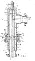
- the strainer illustrated in fig. 1 is made up of a cylindrical structure 1 formed by two sections 1.1 and 1.2, by a strainer structure 2 formed, in turn, by two sections 2.1 and 2.2, by an exhaust-valve 3 and by a valve set 4 which regulates the flow and/or allows the strainer backwash operations.
- All the above components of the device which are separately illustrated in fig.2, are made of plastic or, in alternative, metallic materials not liable to corrosion, or they are made of both plastic and metallic materials, and they can be used to filter sea waters, drainage waters, acid fluids and any other fluids.
- the strainer object of the invention operates by means of a 2 bar hydraulic pressure (at least), without stopping the flow delivery not even during the self-cleaning cycle.
- the device object of the invention includes net strainer baskets, with ring-like extremities, made of different materials, which are already available to be bought, and able to
- the self-cleaning function is regulated by an automatic control system of the flushing valve by means of PLC and it does not necessarily require staff assistance.
- a 9 volt feeding control system may regulate the self-cleaning function, as it happens in micro-irrigation plants.
- the strainer may also be provided with a hand drive.
- the fluid to be filtered enters into the strainer basket 2 through the inlet section 5 and, once filtered, goes out through an outlet section 6 placed at 90° in respect to the longitudinal set of the strainer, near the main plant.
- the outlet section 6 is very wide in order to help the fluid flow, the flow speed is reduced in proximity to the outlet, letting it be equal to the speed inside the strainer.
- the fluid is mainly filtered by section 2 2 of the strainer structure 2.
- a washing phase may occur inside the strainer, during which the exhaust-valve 3 is open, by rotating the relative spindle 3.1, and as a result the residues go out through the exhaust-section 7 in consequence of the propulsion produced by the hydraulic flow inside the strainer.
- the exhaust-section 7 has been illustrated in an embodiment coaxial with the longitudinal axis of the strainer; said section may also be orthogonal with the longitudinal axis, so that the strainer may be placed having its vertical axis perpendicular to the support face.
- the flushing valve 4.1 is open, just like it is when the filter is regularly running.
- the valve set 4 placed between the two sections 1.1 and 1.2 of the external cylindrical covering 1 and between the two sections 2.1 and 2.2 of the cylindrical strainer basket 2, is composed of a ring-like structure 4.6 provided with two couples of grooves 4.3 and 4.4. supporting the two sections which form the strainer basket 2 and also fixing the two sections which form the cylindrical structure 1; the opposite extremities of the strainer baskets 2.1 and 2.2 are provided with collets 2.11 and 2.21 which are inserted into the grooves 1.12 and 1.22 of the external cylindrical structure 1
- the backwash is only performed inside section 2 2 of the strainer basket, not inside section 2.1.
- Said section is cleaned by unscrewing the bolts 9 connecting sections 1.1 and 1.2 of the external cylindrical structure 1, so that section 2.1 of the strainer basket may be pulled out.
- This operation also allows to clean the valve set 4, to perform the relative maintenance and, if necessary, to easily change section 2.2 of the strainer basket.
- the valve set according to the invention which is assembled on the external cylindrical section 1.1 and provided with the strainer basket 2.1, is illustrated from above, through its section and by a three-dimension view, in fig.6, 7 and 8, respectively.
- valve set having a ring-like shape, is provided with holes 4.5 which allow the hydraulic flow not to be interrupted through the interstice even during the backwash cycle.
- Fig.9 and 10 are three-dimension views of the completely assembled strainer seen from the outside.
- Fig.9 illustrates in detail the connection between flanges 1.11 and 1.21 of the external cylindrical structure 1 for the fixing of the valve set 4, the inlet section 5 with the relative flange 5.1 and the exhaust-section 7; fig. 10 instead illustrates in detail the outlet section 6 with the relative flange 6.1.
- ring-like gaskets 10 are inserted into grooves 4.3, 1.12 and 1.22.
- the flanges 1.11 and 1.21 that reciprocally block the two parts of the cylindrical external structure 1, can also not form part of this last, that is, can be constructed in order to position them in the most convenient manner, so that the spindle 4.2, that actions the flushing valve 4.1, does not interfere with the bolts 9 of said flanges.
Landscapes
- Chemical & Material Sciences (AREA)
- Chemical Kinetics & Catalysis (AREA)
- Details Of Valves (AREA)
Abstract
Description
- The invention deals with a valve set for a compound self-cleaning strainer to be used with liquids under pressure.
- Self-cleaning strainers are commonly used to filter natural waters, drainage waters, acid fluids and poor quality waters employed in the cooling system of industries.
- These strainers require a periodic cleaning by means of heavy streams of spouting water which remove the residues.
- Net strainers in use at present are devices in which self-cleaning is accomplished by means of a throttle-valve diverting the flow and an exhaust-valve for the elimination of the residues, both valves being either automatically or manually operated.
- In said strainers, in which the axes of the inlet and outlet sections form a 90° angle, the extremity opposite to the fluid inlet is closed by means of a cap permitting the inspection and the extraction of the strainer basket without removing the connections between the inlet and the outlet sections of the strainer and the pipe system of the plant inside which said strainer is included.
- While the strainer is regularly filtering, the fluid enters into the inlet section, goes through the strainer basket - there into depositing the impurities - and goes out through the outlet section ready to be used; during this phase the exhaust-valve is closed.
- Subsequently, the exhaust-valve opens, and the impurities gathered inside the strainer are discharged.
- While the exhaust-valve is still open, after closing the flushing valve, the washing phase begins inside the strainer, by reversing the flow of the fluid through the filter element, so allowing the impurities to be taken away from the inner surface of the strainer.
- At the end of the backwash cycle (a few seconds) the exhaust-valve is closed, the flushing valve opens and the strainer operates regularly once again.
- The above described strainers are made of either inoxidizable steel or plastic materials such as polypropylene, but there are several drawbacks to the use of these devices.
- Such drawbacks are chiefly due to the fact that a very complex maintenance is to be performed on the devices because, before pulling out the strainer out of the cylindrical structure inside which it is included, it is necessary to unfasten the backwash valve, which is sometimes difficult to accomplish when the strainer is small.
- Another drawback is that the spindle which operates the backwash valve, though supported by the external cylindrical structure, can wear out the strainer basket since it has to go there through
- A further drawback is that it is not possible to wash the basket in its section near the strainer mouth, and that to clean it up it is then necessary to pull out the whole strainer basket, requiring further maintenance.
- Moreover, the strainer basket is assembled and fixed inside the external cylindrical structure by means of bolts or by means of a cylindrical band placed over the basket.
- To avoid the above mentioned drawbacks, this invention solves the problem of the insertion of the flushing valve into a ring-like structure which also fixes the two sections forming the strainer, said two sections being, in turn, reciprocally connected by means of bolts set on two flanges placed at opposite ends.
- The valve contrived and assembled as so far described, as well as the strainer having two separate sections, make it easier to disassemble the appliance and to perform maintenance.
- The invention is described here below in detail and it is illustrated with the figures of the sheets here enclosed, which show respectively:
- Fig.1 - longitudinal section of the strainer in orthogonal projection, showing the valve set according to the invention;
- Fig.2 - orthogonal projection of the longitudinal section of the strainer shown in fig.1, the strainer being not yet assembled;
- Fig.3 - longitudinal section of the strainer shown while regularly operating, with open flushing valve and closed exhaust-valve;
- Fig.4 - longitudinal section of the strainer shown during the inner washing phase, with both the flushing valve and the exhaust-valve open;
- Fig.5 - longitudinal section of the strainer shown during the backwash phase, with closed flushing valve and open exhaust-valve;
- Fig. 6 - the valve set seen from above, with the flushing valve open, and the flange below - also seen from above - by which the external cylindrical structure is applied;
- Fig.7 - longitudinal section of the valve set and of the external cylindrical structure shown in fig.6,
- Fig.8 - three-dimension view of the valve set and of the cylindrical structure shown in fig.7;
- Fig.9 - the strainer seen from the outside, completely assembled, having the axis of the spindle which operates the flushing valve running parallel with the axis of the outlet section;
- Fig. 10 - the strainer shown in fig. 9, illustrated from the opposite side.
-
- The strainer illustrated in fig. 1 is made up of a cylindrical structure 1 formed by two sections 1.1 and 1.2, by a strainer structure 2 formed, in turn, by two sections 2.1 and 2.2, by an exhaust-
valve 3 and by avalve set 4 which regulates the flow and/or allows the strainer backwash operations. - All the above components of the device, which are separately illustrated in fig.2, are made of plastic or, in alternative, metallic materials not liable to corrosion, or they are made of both plastic and metallic materials, and they can be used to filter sea waters, drainage waters, acid fluids and any other fluids.
- The strainer object of the invention operates by means of a 2 bar hydraulic pressure (at least), without stopping the flow delivery not even during the self-cleaning cycle.
- In order to get better filtration results than that usually obtained when using a traditionally perforated pipe, the device object of the invention includes net strainer baskets, with ring-like extremities, made of different materials, which are already available to be bought, and able to The self-cleaning function is regulated by an automatic control system of the flushing valve by means of PLC and it does not necessarily require staff assistance.
- If electric grid is not available, a 9 volt feeding control system may regulate the self-cleaning function, as it happens in micro-irrigation plants.
- The strainer may also be provided with a hand drive.
- Considering the simple construction of the strainer and the materials it is made of, no maintenance is required even over long periods of time
- The regular function of the strainer, in normal conditions, is illustrated in fig.3: the fluid to be filtered enters into the strainer basket 2 through the
inlet section 5 and, once filtered, goes out through anoutlet section 6 placed at 90° in respect to the longitudinal set of the strainer, near the main plant. - The
outlet section 6 is very wide in order to help the fluid flow, the flow speed is reduced in proximity to the outlet, letting it be equal to the speed inside the strainer. - The fluid is mainly filtered by section 2 2 of the strainer structure 2.
- During the filtering phase the exhaust-
valve 3, placed inside the exhaust-section 7, is closed whereas the flushing valve 4.1 is open. - At intervals, a washing phase may occur inside the strainer, during which the exhaust-
valve 3 is open, by rotating the relative spindle 3.1, and as a result the residues go out through the exhaust-section 7 in consequence of the propulsion produced by the hydraulic flow inside the strainer. - The exhaust-
section 7 has been illustrated in an embodiment coaxial with the longitudinal axis of the strainer; said section may also be orthogonal with the longitudinal axis, so that the strainer may be placed having its vertical axis perpendicular to the support face. - During this phase, the residues previously gathered inside the basket 2 are removed.
- During the washing phase, illustrated in fig.4, the flushing valve 4.1 is open, just like it is when the filter is regularly running.
- The valve set 4, placed between the two sections 1.1 and 1.2 of the external cylindrical covering 1 and between the two sections 2.1 and 2.2 of the cylindrical strainer basket 2, is composed of a ring-like structure 4.6 provided with two couples of grooves 4.3 and 4.4. supporting the two sections which form the strainer basket 2 and also fixing the two sections which form the cylindrical structure 1; the opposite extremities of the strainer baskets 2.1 and 2.2 are provided with collets 2.11 and 2.21 which are inserted into the grooves 1.12 and 1.22 of the external cylindrical structure 1
- When the plate 4.1 of the valve set 4 rotates by means of the relative spindle 4.2 until it is perpendicular to the direction of the hydraulic flow, said flow is diverted into the
interstice 8 between the inner surface of the external cylindrical structure 1 and the external surface of the strainer basket 2, after passing through the section 2.1 of the strainer basket, and then it is conveyed partly outside, through theoutlet section 6, and partly through the exhaust-section 7 at the end of the backwash of the strainer basket: during this phase the exhaust-valve 3 is open. - The backwash is only performed inside section 2 2 of the strainer basket, not inside section 2.1.
- Said section is cleaned by unscrewing the
bolts 9 connecting sections 1.1 and 1.2 of the external cylindrical structure 1, so that section 2.1 of the strainer basket may be pulled out. - This operation also allows to clean the
valve set 4, to perform the relative maintenance and, if necessary, to easily change section 2.2 of the strainer basket. - The valve set according to the invention, which is assembled on the external cylindrical section 1.1 and provided with the strainer basket 2.1, is illustrated from above, through its section and by a three-dimension view, in fig.6, 7 and 8, respectively.
- As it can be noticed from the figures, the valve set, having a ring-like shape, is provided with holes 4.5 which allow the hydraulic flow not to be interrupted through the interstice even during the backwash cycle.
- It can also be seen from the figures, that the spindle 4.2, which allows the rotation of the plate 4.1 of the valve, passes through the ring-like structure 4.6 of the valve set 4 without interfering with the hydraulic flow through the holes.
- Fig.9 and 10 are three-dimension views of the completely assembled strainer seen from the outside.
- Fig.9 illustrates in detail the connection between flanges 1.11 and 1.21 of the external cylindrical structure 1 for the fixing of the
valve set 4, theinlet section 5 with the relative flange 5.1 and the exhaust-section 7; fig. 10 instead illustrates in detail theoutlet section 6 with the relative flange 6.1. - As it can be seen from the figures, in order to let the axis B' of the spindle 4.2 which rotates the plate 4.1 of the flushing valve be parallel with the axis B of the
cylindrical outlet section 6, and in order not to have the movement of said spindle hindered by thebolts 9 when the external cylindrical section 1.1 is connected to section 1.2, the bisecting line of the angle α between two holes on the flange 1 21 must be comprehended inside the radial plane passing through the axis A of the cylindrical structure 1 and through the axis B of theoutlet section 6. - In order to have a tighter and more perfect joint between the two sections of the basket and the external cylindrical structure, ring-
like gaskets 10 are inserted into grooves 4.3, 1.12 and 1.22. - The flanges 1.11 and 1.21 that reciprocally block the two parts of the cylindrical external structure 1, can also not form part of this last, that is, can be constructed in order to position them in the most convenient manner, so that the spindle 4.2, that actions the flushing valve 4.1, does not interfere with the
bolts 9 of said flanges.
Claims (8)
- "Modular strainer device for liquid under pressure with flushing valve inserted in an extractable body ", including an external cylindrical structure, a filtering structure, a valve for the interception of the flow and an exhaust-valve, characterised by the fact that the external cylindrical structure (1) is divided into two sections (1.1) and (1.2) each coaxially containing one of the two sections (2.1) and (2.2) of the strainer basket (2), and by the fact that the above sections are reciprocally connected, the flushing valve set (4) being placed between them, the two sections of the external cylindrical structure being provided with flanges (1.11) and (1.21) so that they can be fixed to the above said valve set by means of bolts (9).
- Strainer as claimed in claim 1), characterised by the fact that the exhaust-section (7) is coaxial with the longitudinal axis ofthe strainer or, in alternative, orthogonal to said axis
- Strainer as claimed in claim 1), characterised by the fact the flushing valve set (4) is made of a ring-like structure (4.6) provided with longitudinal holes (4.5) allowing the hydraulic flow to pass through when the valve for the interception of flow (4.1) is closed in order to let the fluid pass from the first section (2.1) to the second section (2.2) of the strainer basket through the interstice (8) formed between the external surface of the strainer basket (2) and the inner surface of the external cylindrical structure (1), when it is necessary to backwash the strainer and remove the residues from the filtering surface of said basket (2), the ring-like structure (4.6) being provided with two opposite round grooves (4.4) for the insertion of the round extremities of the two external cylindrical structures (1.1) (1.2), and being also provided with two opposite round grooves (4.3) through which the filtering structures (2.1) (2.2) are fastened, the opposite extremities (2.11) (2.21) of said filtering structures being inserted into grooves (1.12) (1.22) inside the two external cylindrical structures (1.1) (1.2)
- Strainer as claimed in previous claims, characterised by the fact that the plane passing through the longitudinal axis (A) of the cylindrical structure (1) and through the axis (B) of the outlet section (6) of said cylindrical structure, comprehends the bisecting line (BS) of the angle α formed by two consecutive holes - opposite the outlet section (6) - on the flange (1.21) joined to the cylindrical structure (1.2).
- Strainer as claimed in previous claims, characterised by the fact that the spindle (4.2) which rotates the flushing valve (4.1), also supports said flushing valve, and by the fact that said spindle passes through the ring-like structure (4 6) of the valve set (4) without perforating the strainer baskets, the protruding extremity of said spindle passing in fact through said ring-like structure outside its filtering sections.
- Strainer as claimed in previous claims, characterised by the fact that its components are completely made of plastic or, in alternative, metallic materials not liable to corrosion, or they are made of both plastic and metallic materials.
- Strainer as claimed in claims 1) and 3), characterised by the fact that the joint of the two structures (2.1) and (2.2) of the strainer basket (2) to the valve set (4) and to the external cylindrical structure (1) is obtained by means of suitable ring-like gaskets (10) inserted into grooves (4.3) of the valve set, and into grooves (1.12) and (1.22) of the external cylindrical structure.
- Strainer as claimed in claim 1), characterised by the fact that the flanges (1.11) and (1 21)may be incorporated or not, to the cylindrical structure (1)
Priority Applications (1)
| Application Number | Priority Date | Filing Date | Title |
|---|---|---|---|
| EP03425222A EP1466655A1 (en) | 2003-04-08 | 2003-04-08 | Modular strainer device for liquid under pressure with flushing valve inserted in an extractable body |
Applications Claiming Priority (1)
| Application Number | Priority Date | Filing Date | Title |
|---|---|---|---|
| EP03425222A EP1466655A1 (en) | 2003-04-08 | 2003-04-08 | Modular strainer device for liquid under pressure with flushing valve inserted in an extractable body |
Publications (1)
| Publication Number | Publication Date |
|---|---|
| EP1466655A1 true EP1466655A1 (en) | 2004-10-13 |
Family
ID=32865114
Family Applications (1)
| Application Number | Title | Priority Date | Filing Date |
|---|---|---|---|
| EP03425222A Withdrawn EP1466655A1 (en) | 2003-04-08 | 2003-04-08 | Modular strainer device for liquid under pressure with flushing valve inserted in an extractable body |
Country Status (1)
| Country | Link |
|---|---|
| EP (1) | EP1466655A1 (en) |
Cited By (2)
| Publication number | Priority date | Publication date | Assignee | Title |
|---|---|---|---|---|
| FR2997024A1 (en) * | 2012-10-23 | 2014-04-25 | Snecma | Filter for hydraulic system that is utilized in aeronautical field to protect fuel system while carburizing airplane engine, has passage connecting two orifices, and controllable valve interposed on passage and placed in close/open position |
| CN114206468A (en) * | 2019-08-19 | 2022-03-18 | 阿法拉伐莫阿蒂股份公司 | Filter unit with improved cover assembly |
Citations (1)
| Publication number | Priority date | Publication date | Assignee | Title |
|---|---|---|---|---|
| US4339333A (en) * | 1978-03-15 | 1982-07-13 | Alfa-Laval Ab | Filtration device |
-
2003
- 2003-04-08 EP EP03425222A patent/EP1466655A1/en not_active Withdrawn
Patent Citations (1)
| Publication number | Priority date | Publication date | Assignee | Title |
|---|---|---|---|---|
| US4339333A (en) * | 1978-03-15 | 1982-07-13 | Alfa-Laval Ab | Filtration device |
Cited By (4)
| Publication number | Priority date | Publication date | Assignee | Title |
|---|---|---|---|---|
| FR2997024A1 (en) * | 2012-10-23 | 2014-04-25 | Snecma | Filter for hydraulic system that is utilized in aeronautical field to protect fuel system while carburizing airplane engine, has passage connecting two orifices, and controllable valve interposed on passage and placed in close/open position |
| CN114206468A (en) * | 2019-08-19 | 2022-03-18 | 阿法拉伐莫阿蒂股份公司 | Filter unit with improved cover assembly |
| US11801460B2 (en) | 2019-08-19 | 2023-10-31 | Alfa Laval Moatti Sas | Filtering unit with improved cover assembly |
| CN114206468B (en) * | 2019-08-19 | 2023-12-29 | 阿法拉伐莫阿蒂股份公司 | Filtration unit with improved cover assembly |
Similar Documents
| Publication | Publication Date | Title |
|---|---|---|
| JP5363429B2 (en) | Bucket type strainer | |
| US11879236B2 (en) | Intake filter for water collection system with pressure activated backwash valve | |
| EP2670506B1 (en) | Reversible-flow filter with scavenging device | |
| CN102921231B (en) | Fully-automatic back-flushing type self-cleaning filter | |
| JP4870466B2 (en) | Filtration equipment for liquid smoke system | |
| JP2003502139A (en) | Filter with vacuum cleaning head | |
| KR101064635B1 (en) | Self-cleaning filter | |
| US9962633B2 (en) | Disk type filtering apparatus | |
| JP2011140010A (en) | Strainer and strainer facility | |
| KR20100000395A (en) | Auto screen washing type's filtering apparatus using fluis pressure | |
| EP1466655A1 (en) | Modular strainer device for liquid under pressure with flushing valve inserted in an extractable body | |
| CN109173386A (en) | A kind of centrifugation backwashing sewage water filter device | |
| CN109731386A (en) | A kind of sewage filter device with automatic back-flushing function | |
| JPS62266112A (en) | Self-purifying type filter | |
| KR102612079B1 (en) | A Automatic precision filtration device | |
| JPH03505547A (en) | Fluid filtration method and filter for implementing it | |
| KR200207850Y1 (en) | Strainer having a basket for collecting foreign material | |
| KR200348744Y1 (en) | Rotate type filtering equipment | |
| JP6378592B2 (en) | strainer | |
| JP2005193161A (en) | System for backwashing strainer | |
| JP2006082031A (en) | Y-strainer | |
| US5167807A (en) | Apparatus for in-line recovery of particles from a flowing fluid | |
| KR102751211B1 (en) | Strainer for removing foreign substances from water pipes | |
| RU173675U1 (en) | The filter for cleaning food liquids from suspensions | |
| KR960009122Y1 (en) | Automatic cleaning device of Y-cylinder strainer |
Legal Events
| Date | Code | Title | Description |
|---|---|---|---|
| PUAI | Public reference made under article 153(3) epc to a published international application that has entered the european phase |
Free format text: ORIGINAL CODE: 0009012 |
|
| AK | Designated contracting states |
Kind code of ref document: A1 Designated state(s): AT BE BG CH CY CZ DE DK EE ES FI FR GB GR HU IE IT LI LU MC NL PT RO SE SI SK TR |
|
| AX | Request for extension of the european patent |
Extension state: AL LT LV MK |
|
| 17P | Request for examination filed |
Effective date: 20050413 |
|
| AKX | Designation fees paid |
Designated state(s): AT BE BG CH CY CZ DE DK EE ES FI FR GB GR HU IE IT LI LU MC NL PT RO SE SI SK TR |
|
| 17Q | First examination report despatched |
Effective date: 20051227 |
|
| STAA | Information on the status of an ep patent application or granted ep patent |
Free format text: STATUS: THE APPLICATION IS DEEMED TO BE WITHDRAWN |
|
| 18D | Application deemed to be withdrawn |
Effective date: 20061221 |