EP1465507B1 - Buckle for self-locking and adjustment fixing of a belt - Google Patents
Buckle for self-locking and adjustment fixing of a belt Download PDFInfo
- Publication number
- EP1465507B1 EP1465507B1 EP03715020A EP03715020A EP1465507B1 EP 1465507 B1 EP1465507 B1 EP 1465507B1 EP 03715020 A EP03715020 A EP 03715020A EP 03715020 A EP03715020 A EP 03715020A EP 1465507 B1 EP1465507 B1 EP 1465507B1
- Authority
- EP
- European Patent Office
- Prior art keywords
- button
- ring
- base
- fixing loop
- loop according
- Prior art date
- Legal status (The legal status is an assumption and is not a legal conclusion. Google has not performed a legal analysis and makes no representation as to the accuracy of the status listed.)
- Expired - Lifetime
Links
- 230000006835 compression Effects 0.000 claims description 3
- 238000007906 compression Methods 0.000 claims description 3
- 238000003780 insertion Methods 0.000 claims description 2
- 230000037431 insertion Effects 0.000 claims description 2
- 238000006073 displacement reaction Methods 0.000 description 3
- 239000002184 metal Substances 0.000 description 2
- 230000015572 biosynthetic process Effects 0.000 description 1
- 230000009194 climbing Effects 0.000 description 1
- 238000012423 maintenance Methods 0.000 description 1
- 230000002747 voluntary effect Effects 0.000 description 1
Images


Classifications
-
- A—HUMAN NECESSITIES
- A44—HABERDASHERY; JEWELLERY
- A44B—BUTTONS, PINS, BUCKLES, SLIDE FASTENERS, OR THE LIKE
- A44B11/00—Buckles; Similar fasteners for interconnecting straps or the like, e.g. for safety belts
-
- A—HUMAN NECESSITIES
- A44—HABERDASHERY; JEWELLERY
- A44B—BUTTONS, PINS, BUCKLES, SLIDE FASTENERS, OR THE LIKE
- A44B11/00—Buckles; Similar fasteners for interconnecting straps or the like, e.g. for safety belts
- A44B11/25—Buckles; Similar fasteners for interconnecting straps or the like, e.g. for safety belts with two or more separable parts
- A44B11/28—Buckles; Similar fasteners for interconnecting straps or the like, e.g. for safety belts with two or more separable parts with hooks engaging end-pieces on the strap
-
- F—MECHANICAL ENGINEERING; LIGHTING; HEATING; WEAPONS; BLASTING
- F16—ENGINEERING ELEMENTS AND UNITS; GENERAL MEASURES FOR PRODUCING AND MAINTAINING EFFECTIVE FUNCTIONING OF MACHINES OR INSTALLATIONS; THERMAL INSULATION IN GENERAL
- F16B—DEVICES FOR FASTENING OR SECURING CONSTRUCTIONAL ELEMENTS OR MACHINE PARTS TOGETHER, e.g. NAILS, BOLTS, CIRCLIPS, CLAMPS, CLIPS OR WEDGES; JOINTS OR JOINTING
- F16B45/00—Hooks; Eyes
- F16B45/02—Hooks with pivoting or elastically bending closing member
- F16B45/027—Hooks with pivoting or elastically bending closing member and having position-locking means for the closing member
-
- F—MECHANICAL ENGINEERING; LIGHTING; HEATING; WEAPONS; BLASTING
- F16—ENGINEERING ELEMENTS AND UNITS; GENERAL MEASURES FOR PRODUCING AND MAINTAINING EFFECTIVE FUNCTIONING OF MACHINES OR INSTALLATIONS; THERMAL INSULATION IN GENERAL
- F16B—DEVICES FOR FASTENING OR SECURING CONSTRUCTIONAL ELEMENTS OR MACHINE PARTS TOGETHER, e.g. NAILS, BOLTS, CIRCLIPS, CLAMPS, CLIPS OR WEDGES; JOINTS OR JOINTING
- F16B45/00—Hooks; Eyes
- F16B45/04—Hooks with sliding closing member
- F16B45/045—Hooks with sliding closing member provided with position-locking means for the closing member
-
- Y—GENERAL TAGGING OF NEW TECHNOLOGICAL DEVELOPMENTS; GENERAL TAGGING OF CROSS-SECTIONAL TECHNOLOGIES SPANNING OVER SEVERAL SECTIONS OF THE IPC; TECHNICAL SUBJECTS COVERED BY FORMER USPC CROSS-REFERENCE ART COLLECTIONS [XRACs] AND DIGESTS
- Y10—TECHNICAL SUBJECTS COVERED BY FORMER USPC
- Y10T—TECHNICAL SUBJECTS COVERED BY FORMER US CLASSIFICATION
- Y10T24/00—Buckles, buttons, clasps, etc.
- Y10T24/34—Combined diverse multipart fasteners
- Y10T24/3401—Buckle
- Y10T24/3416—Buckle and hook
-
- Y—GENERAL TAGGING OF NEW TECHNOLOGICAL DEVELOPMENTS; GENERAL TAGGING OF CROSS-SECTIONAL TECHNOLOGIES SPANNING OVER SEVERAL SECTIONS OF THE IPC; TECHNICAL SUBJECTS COVERED BY FORMER USPC CROSS-REFERENCE ART COLLECTIONS [XRACs] AND DIGESTS
- Y10—TECHNICAL SUBJECTS COVERED BY FORMER USPC
- Y10T—TECHNICAL SUBJECTS COVERED BY FORMER US CLASSIFICATION
- Y10T24/00—Buckles, buttons, clasps, etc.
- Y10T24/40—Buckles
- Y10T24/4002—Harness
- Y10T24/4005—Combined buckles and snap hooks
-
- Y—GENERAL TAGGING OF NEW TECHNOLOGICAL DEVELOPMENTS; GENERAL TAGGING OF CROSS-SECTIONAL TECHNOLOGIES SPANNING OVER SEVERAL SECTIONS OF THE IPC; TECHNICAL SUBJECTS COVERED BY FORMER USPC CROSS-REFERENCE ART COLLECTIONS [XRACs] AND DIGESTS
- Y10—TECHNICAL SUBJECTS COVERED BY FORMER USPC
- Y10T—TECHNICAL SUBJECTS COVERED BY FORMER US CLASSIFICATION
- Y10T24/00—Buckles, buttons, clasps, etc.
- Y10T24/40—Buckles
- Y10T24/4079—Sliding part of wedge
- Y10T24/4081—Hook attached
-
- Y—GENERAL TAGGING OF NEW TECHNOLOGICAL DEVELOPMENTS; GENERAL TAGGING OF CROSS-SECTIONAL TECHNOLOGIES SPANNING OVER SEVERAL SECTIONS OF THE IPC; TECHNICAL SUBJECTS COVERED BY FORMER USPC CROSS-REFERENCE ART COLLECTIONS [XRACs] AND DIGESTS
- Y10—TECHNICAL SUBJECTS COVERED BY FORMER USPC
- Y10T—TECHNICAL SUBJECTS COVERED BY FORMER US CLASSIFICATION
- Y10T24/00—Buckles, buttons, clasps, etc.
- Y10T24/47—Strap-end-attaching devices
- Y10T24/4755—Hook
Definitions
- the invention relates to a self-locking fastening loop comprising a base equipped with a hook for attaching a retaining ring, and a movable operating knob between a closed position and an open position. of the ball, respectively to retain and release said retaining ring (see for example the document CH-A-674 302).
- the attachment loop may for example, equip a strap with a belt or a climbing or caving harness. It is imperative for reasons of handling, that the opening of the loop is done without having to remove the strap, the latter must be additionally adjustable. On the other hand, for security reasons, there can be no unexpected opening of the loop.
- the object of the invention is to provide a fastening loop avoiding inadvertent opening, and does not require the removal of the strap during a voluntary opening.
- the locking means comprises a latch arranged pivotably mounted on an axis between a locked position and an unlocked position, and a return spring urging the automatic reset of said latch in the locked position to prevent displacement. from the operating knob to the open position.
- the base comprises a stirrup arranged as a hinge support of the operating knob, and a first hole for the introduction of a button leg during the passage to the open position.
- the base has a second hole located under the adjustment ring for the passage of the strap.
- the retaining ring is provided with a stud intended to penetrate into a hole of the hook to limit the angular movement of the retaining ring under heavy load.
- the locking means is formed by a compression spring bearing on the base, and urging the button towards the closed position.
- a fastening loop 10 is intended to receive a retaining ring 12 which is secured to the end of a strap 14 attachment, for example a belt or harness. The other end of the strap is attached to the buckle 10.
- the fastening loop 10 comprises a metal base 16 shaped hook 18 at the front, and a stirrup 20 at the rear.
- the hook 18 cooperates by snapping with the ring 12 when closing the fastening loop 10, while the stirrup 20 serves as a hinge support for a knob 22 maneuvering.
- the latter is pivotally mounted between a closed position for trapping the ring 12 inside the hook 18, and an open position for the formation of a release interval of the ring 12.
- the button 22 can be made of plastic or metal.
- a rotary lock 24 or rocker is associated with the button 22 to prevent it from moving unexpectedly to the open position.
- the latch 24 can pivot for this purpose about an axis 26 between a locked position, and an unlocked position.
- a return spring 28 (FIG. 5A), for example a torsion spring, is threaded on the axis 26, and biases the latch 24 clockwise towards the locked position.
- a tab 29 of the button 22 can enter a first hole 27 of the base 16 to allow the ring 12 to be released.
- the ring 12 is provided in the central part with a pin 12a intended to penetrate into an axial orifice of the hook 18 so as to limit the angular displacement of the ring 12 under load in the wrong direction (FIG. 4), and to prevent any engagement against the button 22 may unlock the latch 24 rotary.
- the tab 29 also serves to prevent the displacement of the ring 12 to the right when the button 22 is in the closed position.
- the stud 12a then remains in the orifice 30 (FIGS. 4A and 5).
- the end of the strap 14 located on the side of the loop 10 is adjustable in length through a ring 32 of adjustment integrated in the loop 10 opposite the hook 18. Any effort exerted on the strap 14 in the direction of the arrow F1, causes the movement in the same direction of the adjusting ring 32, so as to block the strap 14 ( Figure 9).
- the base 16 has a second hole 33 for the passage of the strap 14.
- FIGS. 12A to 12E The different phases of mounting of the loop 10 are illustrated in FIGS. 12A to 12E. After assembly of the lock 24 on the button 22, it slides the latter in the direction of the arrow F4, under the two tabs of the stirrup 20 ( Figure 12A).
- the button 22 rises in its housing, and is ready to rotate. It has at the rear a retaining lug 34 for holding the adjusting ring 32 in place.
- the adjustment ring 32 is inserted into the loop 10 at the rear of the stirrup 20.
- the forward tilting of the button 22 causes the spigot 34 to be raised to allow the sliding movement longitudinal direction of the adjusting ring 32.
- Figure 12D shows the loop 10 in a manipulable pre-assembly state.
- the retaining pin 34 is housed in the orifice of the adjusting ring 32, and prevents the latter from coming out by keeping it in contact with the internal face of the base 16.
- the operation of the fastening loop 10 is as follows:
- any attempt to voluntarily press the button 22 does not allow the opening as long as the latch 24 remains in the locked position, ie by pressing on the base 16. An inadvertent opening of the Loop 10 is thus made impossible.
- the first manual action of the unlocking action is shown in FIGS. 7 to 8.
- the retaining ring 12 can now be unhooked from the hook 18, as shown in FIG.
- the release of the button 22 provides an automatic reset of the latch 24 and return button 22 in the position of Figure 5.
- the lock 24 is replaced by a compression spring 40 interposed between the button 22 and the base 16.
Landscapes
- Engineering & Computer Science (AREA)
- General Engineering & Computer Science (AREA)
- Mechanical Engineering (AREA)
- Buckles (AREA)
- Purses, Travelling Bags, Baskets, Or Suitcases (AREA)
- Clamps And Clips (AREA)
- Automotive Seat Belt Assembly (AREA)
- Package Frames And Binding Bands (AREA)
- Helmets And Other Head Coverings (AREA)
Abstract
Description
L'invention est relative à une boucle de fixation à auto-verrouillage comprenant une embase équipée d'un crochet pour l'accrochage d'un anneau de retenue, et un bouton de manoeuvre mobile entre une position de fermeture et une position d'ouverture de la boule, respectivement pour retenir et libérer ledit anneau de retenue (voir par exemple le document CH-A-674 302).The invention relates to a self-locking fastening loop comprising a base equipped with a hook for attaching a retaining ring, and a movable operating knob between a closed position and an open position. of the ball, respectively to retain and release said retaining ring (see for example the document CH-A-674 302).
La boucle de fixation peut à titre d'exemple, équiper une sangle d'une ceinture ou d'un baudrier d'escalade ou de spéléologie. Il est impératif pour des raisons de manipulations, que l'ouverture de la boucle s'effectue sans avoir à retirer la sangle, cette dernière devant en plus être réglable. D'autre part, pour des questions de sécurité, il ne peut y avoir d'ouverture inopinée de la boucle.The attachment loop may for example, equip a strap with a belt or a climbing or caving harness. It is imperative for reasons of handling, that the opening of the loop is done without having to remove the strap, the latter must be additionally adjustable. On the other hand, for security reasons, there can be no unexpected opening of the loop.
L'objet de l'invention consiste à réaliser une boucle de fixation évitant toute ouverture intempestive, et ne nécessitant pas le retrait de la sangle lors d'une ouverture volontaire.The object of the invention is to provide a fastening loop avoiding inadvertent opening, and does not require the removal of the strap during a voluntary opening.
La boucle selon l'invention est caractérisée en ce qu'elle comporte:
- un moyen de verrouillage du bouton de manoeuvre en position de fermeture,
- et un anneau de réglage de la longueur de la sangle, ledit anneau étant inséré entre le bouton et l'embase à l'opposé du crochet.
- a locking means of the operating knob in the closed position,
- and a ring for adjusting the length of the strap, said ring being inserted between the button and the base opposite the hook.
Selon un mode de réalisation préférentiel, le moyen de verrouillage comprend un verrou agencé en basculeur monté à pivotement sur un axe entre une position verrouillée et une position déverrouillée, et un ressort de rappel sollicitant le réarmement automatique dudit verrou en position verrouillée pour empêcher le déplacement du bouton de manoeuvre vers la position d'ouverture. L'embase comporte un étrier agencé en support d'articulation du bouton de manoeuvre, et un premier trou pour l'introduction d'une patte du bouton lors du passage vers la position d'ouverture.According to a preferred embodiment, the locking means comprises a latch arranged pivotably mounted on an axis between a locked position and an unlocked position, and a return spring urging the automatic reset of said latch in the locked position to prevent displacement. from the operating knob to the open position. The base comprises a stirrup arranged as a hinge support of the operating knob, and a first hole for the introduction of a button leg during the passage to the open position.
L'embase est dotée d'un deuxième trou situé sous l'anneau de réglage pour le passage de la sangle. L'anneau de retenue est pourvu d'un téton destiné à pénétrer dans un orifice du crochet pour limiter le débattement angulaire de l'anneau de retenue sous forte charge.The base has a second hole located under the adjustment ring for the passage of the strap. The retaining ring is provided with a stud intended to penetrate into a hole of the hook to limit the angular movement of the retaining ring under heavy load.
Selon une variante de réalisation, le moyen de verrouillage est formé par un ressort de compression prenant appui sur l'embase, et sollicitant le bouton vers la position de fermeture.According to an alternative embodiment, the locking means is formed by a compression spring bearing on the base, and urging the button towards the closed position.
D'autres avantages et caractéristiques ressortiront plus clairement de la description qui va suivre de modes particuliers de réalisation de l'invention donnés à titre d'exemples non limitatifs et représentés aux dessins annexés, dans lesquels :
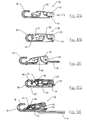
- les figures 1 et 2 sont des vues en perspective de l'ensemble de la boucle selon l'invention représentée respectivement en position de fermeture et en position d'ouverture;
- la figure 3 montre la boucle de la figure 1 vue sous un autre angle ;
- la figure 4 est une vue identique de la figure 3 après basculement de l'anneau vers le bouton ;
- les figures 4A et 5 représentent des vues en coupe longitudinale de la boucle en position de fermeture, et pour deux inclinaisons différentes ;
- la figure 5A illustre une vue en coupe à échelle agrandie du verrou de la figure 5 ;
- la figure 6 est une vue en élévation de la boucle selon la figure 5 ;
- les figures 7 et 8 sont des vues identiques de la boucle de la figure 5, respectivement en cours d'ouverture, et en fin de course d'ouverture ;
- les figures 9 à 11 illustrent les différentes phases de réglage de la sangle ;
- les figures 12A-12E représentent les différentes phases de montage et d'assemblage de la boucle ;
- la figure 13 est une vue identique de la figure 5 d'une variante de réalisation.
- Figures 1 and 2 are perspective views of the entire loop according to the invention shown respectively in the closed position and in the open position;
- Figure 3 shows the loop of Figure 1 seen from another angle;
- Figure 4 is an identical view of Figure 3 after tilting of the ring to the button;
- Figures 4A and 5 show longitudinal sectional views of the loop in the closed position, and for two different inclinations;
- Figure 5A illustrates an enlarged sectional view of the lock of Figure 5;
- Figure 6 is an elevational view of the loop according to Figure 5;
- Figures 7 and 8 are identical views of the loop of Figure 5, respectively during opening, and at the end of the opening stroke;
- Figures 9 to 11 illustrate the different phases of adjustment of the strap;
- Figures 12A-12E show the different phases of assembly and assembly of the loop;
- Figure 13 is an identical view of Figure 5 of an alternative embodiment.
Sur les figures 1 à 8, une boucle de fixation 10 est destinée à recevoir un anneau de retenue 12 auquel est solidarisée l'extrémité d'une sangle 14 d'attache, par exemple d'une ceinture ou d'un harnais. L'autre extrémité de la sangle est attachée à la boucle 10.In Figures 1 to 8, a
La boucle de fixation 10 comporte une embase 16 métallique conformée en crochet 18 à la partie antérieure, et un étrier 20 à la partie postérieure. Le crochet 18 coopère par encliquetage avec l'anneau 12 lors de la fermeture de la boucle de fixation 10, tandis que l'étrier 20 sert de support d'articulation à un bouton 22 de manoeuvre. Ce dernier est monté à pivotement entre une position de fermeture pour emprisonner l'anneau 12 à l'intérieur du crochet 18, et une position d'ouverture pour la formation d'un intervalle de libération de l'anneau 12. Le bouton 22 peut être en matière plastique ou métallique.The
Un verrou 24 rotatif ou basculeur est associé au bouton 22 pour l'empêcher de se déplacer intempestivement vers la position d'ouverture. Le verrou 24 peut pivoter à cet effet autour d'un axe 26 entre une position verrouillée, et une position déverrouillée. Un ressort de rappel 28 (figure 5A), par exemple un ressort à torsion, est enfilé sur l'axe 26, et sollicite le verrou 24 dans le sens horaire vers la position verrouillée. Dans la position déverrouillée, une patte 29 du bouton 22 peut pénétrer dans un premier trou 27 de l'embase 16 pour autoriser le décrochage de l'anneau 12. Pour pousser le bouton 22 vers le bas dans le sens d'ouverture de la boucle 10, il est nécessaire au préalable de faire tourner le verrou basculeur 24 vers la position déverrouillée à l'encontre de la force de rappel du ressort 28 (figures 7 et 8).A
L'anneau 12 est pourvu dans la partie centrale d'un téton 12a destiné à pénétrer dans un orifice 30 axial du crochet 18 de manière à limiter le débattement angulaire de l'anneau 12 sous charge dans une mauvaise direction (figure 4), et à empêcher tout engagement contre le bouton 22 risquant de déverrouiller le verrou 24 rotatif.The
La patte 29 sert également à empêcher le déplacement de l'anneau 12 vers la droite lorsque le bouton 22 se trouve en position de fermeture. Le téton 12a reste alors maintenu dans l'orifice 30 (figures 4A et 5).The
En référence aux figures 9 à 11, l'extrémité de la sangle 14 située du côté de la boucle 10, est ajustable en longueur grâce à un anneau 32 de réglage intégré à la boucle 10 à l'opposé du crochet 18. Tout effort exercé sur la sangle 14 dans le sens de la flèche F1, provoque le déplacement dans le même sens de l'anneau de réglage 32, de manière à bloquer la sangle 14 (figure 9). L'embase 16 est dotée d'un deuxième trou 33 pour le passage de la sangle 14.Referring to Figures 9 to 11, the end of the
Pour décoincer la sangle 14, il suffit de repousser l'anneau de réglage 32 dans le sens de la flèche F2 (figure 10), ou de faire basculer la boucle 10 dans le sens de la flèche F3 (figure 11). Le réglage peut être ensuite opéré en tirant sur l'un des brins de la sangle 14.To loosen the
Les différentes phases de montage de la boucle 10 sont illustrées sur les figures 12A à 12E. Après assemblage du verrou 24 sur le bouton 22, on glisse ce dernier dans le sens de la flèche F4, sous les deux pattes d'articulation de l'étrier 20 (figure 12A).The different phases of mounting of the
Sur la figure 12B, le bouton 22 remonte dans son logement, et est prêt à pivoter. Il présente à l'arrière un ergot 34 de retenue destiné à maintenir l'anneau de réglage 32 en place.In Figure 12B, the
Sur la figure 12C, l'anneau de réglage 32 est introduit dans la boucle 10 à l'arrière de l'étrier 20. Le basculement vers l'avant du bouton 22 provoque le relèvement de l'ergot 34 pour autoriser le mouvement de glissement longitudinal de l'anneau de réglage 32.In FIG. 12C, the
La figure 12D montre la boucle 10 dans un état de prémontage manipulable. L'ergot 34 de retenue est logé dans l'orifice de l'anneau de réglage 32, et empêche ce dernier de ressortir en le maintenant en contact avec la face interne de l'embase 16.Figure 12D shows the
Sur la figue 12 E, l'introduction de la sangle 14 par le trou 33 assure le maintien de l'anneau de réglage 32, lequel solidarise le bouton 22 dans l'étrier 20. Un tel montage de la boucle 10 s'effectue sans outil, et est rendu indémontable suite à l'insertion de la sangle 14.In FIG. 12E, the introduction of the
Le fonctionnement de la boucle de fixation 10 est le suivant :The operation of the
Sur les figures 1 ,5 et 5A, la boucle 10 se trouve en position de fermeture, et le bouton 22 est bloqué par le verrou 24 en position verrouillée par le ressort 28. L'anneau de retenue 12 est ancré positivement dans le crochet 18 de l'embase 16.In Figures 1, 5 and 5A, the
Dans la figure 6, toute tentative d'appui volontaire sur le bouton 22 ne permet pas l'ouverture tant que le verrou 24 reste en position verrouillée, c'est à dire en prenant appui sur l'embase 16. Une ouverture intempestive de la boucle 10 est ainsi rendue impossible.In FIG. 6, any attempt to voluntarily press the
La commande d'ouverture nécessite deux actions distinctes consécutives :
- une première action de déverrouillage du verrou 24 et d'appui sur le bouton 22 pour ouvrir la boucle 10 ;
- une deuxième action pour décrocher l'anneau 12 du
crochet 18, en le déplaçant dans le sens opposé à celui de la tension de la sangle 14.
- a first unlocking action of the
latch 24 and pressing thebutton 22 to open theloop 10; - a second action to unhook the
ring 12 of thehook 18, moving it in the opposite direction to that of the tension of thestrap 14.
La première action manuelle de l'action de déverrouillage est représentée sur les figures 7 à 8.The first manual action of the unlocking action is shown in FIGS. 7 to 8.
Sur la figure 7, après rotation du verrou 24 dans le sens horaire, le point de contact du verrou 24 sur l'embase 16 se trouve en arrière de l'axe 26 autorisant le basculement du capot 22 dans le même sens.In Figure 7, after rotation of the
Sur la figure 8, le verrou 24 se trouve en position déverrouillée, permettant l'ouverture complète de la boucle 10.In FIG. 8, the
L'anneau de retenue 12 peut maintenant être décroché du crochet 18, comme indiqué à la figure 2.The retaining
Le relâchement du bouton 22 permet d'obtenir un réarmement automatique du verrou 24 et de rappel du bouton 22 dans la position de la figure 5.The release of the
Selon une variante de réalisation illustrée à la figure 13, le verrou 24 est remplacé par un ressort 40 de compression intercalé entre le bouton 22 et l'embase 16.According to an alternative embodiment illustrated in FIG. 13, the
Pour obtenir l'ouverture de la boucle, il suffit d'appuyer sur le bouton 22 pour autoriser le décrochage de l'anneau de retenue 12.To obtain the opening of the loop, simply press the
Claims (8)
- A self-locking fixing loop comprising a base (16) equipped with a clasp (18) for hooking a retaining ring (12) thereon, and an operating button (22) movable between a closed position and an open position of the loop, respectively to hold and release said retaining ring,
characterized in that it comprises in addition:- a locking means for locking the operating button (22) in the closed position,- and an adjustment ring (32) for adjusting the length of the strap (14), said ring being inserted between the button (22) and the base (16) opposite the clasp (18). - The fixing loop according to claim 1, characterized in that the locking means comprises a catch (24) arranged as a rocker pivotally mounted on a spindle (26) between a locked position and an unlocked position, and a return spring (28) urging automatic resetting of said catch (24) in the locked position to prevent the operating button (22) from moving to the open position.
- The fixing loop according to claim 1, characterized in that the locking means is formed by a compression spring (40) pressing on the base (16) and urging the button (22) to the closed position.
- The fixing loop according to claim 1, characterized in that the base (16) comprises a flange (20) arranged as a support for articulation of the operating button (22), and a first hole (27) for insertion of a lug (29) of the button (22) when movement takes place to the open position.
- The fixing loop according to claim 2, characterized in that the return spring (28) is formed by a torsion spring wound on the spindle (26) of the catch (24).
- The fixing loop according to one of the foregoing claims, characterized in that the retaining ring (12) is provided with a pin (12a) designed to enter a hole (30) of the clasp (18) to limit the angular movement of the retaining ring (12) under a strong load.
- The fixing loop according to one of the foregoing claims, characterized in that the base (16) is provided with a second hole (33) situated under the adjustment ring (32) for passage of the strap (14).
- The fixing loop according to one of the foregoing claims, characterized in that the operating button (22) is equipped with a spigot (34) designed to keep the adjustment ring (32) in place when the button (22) is in the closed position.
Applications Claiming Priority (3)
| Application Number | Priority Date | Filing Date | Title |
|---|---|---|---|
| FR0200593A FR2834870B1 (en) | 2002-01-18 | 2002-01-18 | FIXING LOOP WITH SELF-LOCKING AND ADJUSTMENT OF A STRAP |
| FR0200593 | 2002-01-18 | ||
| PCT/FR2003/000146 WO2003059107A1 (en) | 2002-01-18 | 2003-01-17 | Buckle for self-locking and adjustment fixing of a belt |
Publications (2)
| Publication Number | Publication Date |
|---|---|
| EP1465507A1 EP1465507A1 (en) | 2004-10-13 |
| EP1465507B1 true EP1465507B1 (en) | 2006-11-29 |
Family
ID=8871342
Family Applications (1)
| Application Number | Title | Priority Date | Filing Date |
|---|---|---|---|
| EP03715020A Expired - Lifetime EP1465507B1 (en) | 2002-01-18 | 2003-01-17 | Buckle for self-locking and adjustment fixing of a belt |
Country Status (9)
| Country | Link |
|---|---|
| US (1) | US6802109B2 (en) |
| EP (1) | EP1465507B1 (en) |
| JP (1) | JP4593111B2 (en) |
| KR (1) | KR100895229B1 (en) |
| AT (1) | ATE346520T1 (en) |
| DE (1) | DE60310029T2 (en) |
| ES (1) | ES2278152T3 (en) |
| FR (1) | FR2834870B1 (en) |
| WO (1) | WO2003059107A1 (en) |
Cited By (2)
| Publication number | Priority date | Publication date | Assignee | Title |
|---|---|---|---|---|
| US8516666B2 (en) | 2010-07-02 | 2013-08-27 | Zedel | Attachment buckle with double locking |
| DE102022202632B3 (en) | 2022-03-17 | 2023-08-10 | Edelrid Gmbh & Co. Kg | Self-locking belt buckle |
Families Citing this family (31)
| Publication number | Priority date | Publication date | Assignee | Title |
|---|---|---|---|---|
| US7070295B1 (en) * | 2005-10-14 | 2006-07-04 | Wen Sung Lee | Light device for attaching to objects |
| DE202006016188U1 (en) * | 2006-10-23 | 2006-12-21 | Skylotec Gmbh | Plug lock e.g. for connecting two belt ends, has lock part and plug-in part with lock part having lateral end to receive plug-in part and belt having lateral end |
| US8800563B2 (en) * | 2007-11-05 | 2014-08-12 | Resmed Limited | Headgear for a respiratory mask and a method for donning a respiratory mask |
| CN102421318A (en) * | 2009-04-24 | 2012-04-18 | 比约恩婴儿用品公司 | Band lock for a child carrying device |
| US8297667B2 (en) * | 2009-06-08 | 2012-10-30 | Ford Global Technologies, Llc | Lockable latch |
| US8695176B2 (en) | 2009-07-13 | 2014-04-15 | Cequent Consumer Products | Adjustable tarp strap |
| US8225970B2 (en) * | 2010-01-29 | 2012-07-24 | Evenflo Company, Inc. | Infant carrier buckle |
| US20110244741A1 (en) * | 2010-03-31 | 2011-10-06 | The Farwell Company, LLC | Personal floatation device |
| AT12861U1 (en) | 2011-05-27 | 2013-01-15 | Aba Hoertnagl Gmbh | buckle |
| US9500438B2 (en) | 2011-09-09 | 2016-11-22 | Magpul Industries Corp. | Lockable snap-clip fastener |
| US8544153B2 (en) * | 2011-09-09 | 2013-10-01 | Magpul Industries Corp | Lockable snap-clip fastener |
| AT512224B1 (en) * | 2011-12-02 | 2013-08-15 | Aba Hoertnagl Gmbh | BUCKLE |
| EP2609825B1 (en) * | 2011-12-28 | 2014-07-30 | Hultafors Group AB | A Locking Clip and a Locking Arrangement |
| US9009931B2 (en) | 2012-03-01 | 2015-04-21 | Matthew Jensen | Versatile, convertible messenger bag |
| US9199571B2 (en) | 2012-07-03 | 2015-12-01 | Cequent Consumer Products, Inc. | Adjustable flexible cargo strap |
| US9339086B2 (en) * | 2012-12-27 | 2016-05-17 | Jerry R. Hill Innovations, Inc. | Adjustable loop load tie-down strap |
| US9936679B2 (en) * | 2014-04-23 | 2018-04-10 | Drew A. Roberdeaux | Pet leash accessory assembly |
| AU2015343810B2 (en) | 2014-11-07 | 2020-07-16 | Fisher & Paykel Healthcare Limited | Breathing apparatus |
| CN204445257U (en) * | 2015-01-12 | 2015-07-08 | 香港多耐福有限公司 | A kind of ribbon adjustment stay hook |
| WO2017034532A1 (en) | 2015-08-22 | 2017-03-02 | Jerry Hill Innovations, Inc. | Improved tie-down wrap device for securing loads and methods of use |
| US9986790B2 (en) * | 2015-11-30 | 2018-06-05 | The Prophet Corporation | Buckle for exercise strap |
| WO2018147941A1 (en) * | 2017-02-08 | 2018-08-16 | Illinois Tool Works Inc. | Attachment clip assembly |
| FR3069138B1 (en) * | 2017-07-18 | 2019-08-23 | Zedel | FASTENING BUCKLE AND HARNESS HAVING SUCH A LOOP. |
| USD876019S1 (en) * | 2018-01-18 | 2020-02-18 | Zedel | Harness buckle |
| AT521157B1 (en) | 2018-06-13 | 2019-11-15 | Aba Hoertnagl Gmbh | Buckle, in particular buckle |
| WO2020005801A1 (en) * | 2018-06-28 | 2020-01-02 | Hoist Fitness Systems, Inc. | Interchangeable arm quick release mechanism for chest press exercise machine |
| USD1032403S1 (en) * | 2019-12-20 | 2024-06-25 | Zedel | Buckle |
| DE202021104483U1 (en) * | 2020-08-24 | 2022-02-22 | Cmc Rescue, Inc. | articulated buckle |
| CN114027591B (en) * | 2020-09-09 | 2024-02-20 | 联扬塑胶(深圳)有限公司 | Toggle unlocking buckle device |
| CA3213666A1 (en) * | 2021-04-01 | 2022-10-06 | William Oren WEKELL | Monitoring changes in volume and properties of human interstitial fluid and electro-mechanical design of an optical device to accomplish the same |
| FR3125687B1 (en) * | 2021-07-27 | 2024-06-21 | Zedel | ADJUSTMENT SYSTEM WITH IMPROVED OPERATION, METHOD FOR MANUFACTURING SUCH AN ADJUSTMENT SYSTEM AND ADJUSTMENT METHOD |
Family Cites Families (21)
| Publication number | Priority date | Publication date | Assignee | Title |
|---|---|---|---|---|
| US536390A (en) * | 1895-03-26 | Buckle | ||
| US292164A (en) * | 1884-01-22 | John gibbons | ||
| US372821A (en) * | 1887-11-08 | Buckle | ||
| US429137A (en) * | 1890-06-03 | Buckle | ||
| US263176A (en) * | 1882-08-22 | Rope-coupling and snap-hook | ||
| US889013A (en) * | 1907-07-02 | 1908-05-26 | John W Hutchison | Combined snap-hook and buckle. |
| US2514656A (en) * | 1943-09-22 | 1950-07-11 | Frank G Manson | Self-locking snap hook |
| US2498334A (en) * | 1945-10-15 | 1950-02-21 | Macon M Garner | Saddle buckle |
| JPS5256086Y1 (en) * | 1968-03-01 | 1977-12-19 | ||
| JPS4720418U (en) * | 1971-02-06 | 1972-11-08 | ||
| JPS5542013Y2 (en) * | 1974-02-02 | 1980-10-02 | ||
| US3992756A (en) * | 1974-12-13 | 1976-11-23 | Waterbury Buckle Company | Separable fastener |
| US4074401A (en) * | 1976-12-16 | 1978-02-21 | East/West Industries, Inc. | Snap assembly |
| US4171555A (en) * | 1978-05-01 | 1979-10-23 | Illinois Tool Works Inc. | Buckle |
| JPS6128416U (en) * | 1984-07-25 | 1986-02-20 | フルヤ工業株式会社 | Batsukuru |
| JPH0716322Y2 (en) * | 1987-10-21 | 1995-04-19 | 昭栄化工株式会社 | String fastener |
| CH674302A5 (en) * | 1988-01-26 | 1990-05-31 | Repapress Ag | Safety closure for belts - has lock frame into which closure hook can hook where it is prevented from disengagement by locking member |
| JPH0542729Y2 (en) * | 1988-09-13 | 1993-10-27 | ||
| US4928360A (en) * | 1989-07-10 | 1990-05-29 | Wilbanks John W | Board anchor |
| TW312101U (en) * | 1996-09-03 | 1997-08-01 | Taiwan Ind Fastener Corp | Buckle with elastic release feature |
| US6023820A (en) * | 1998-10-20 | 2000-02-15 | Evenflo Company, Inc. | Soft carrier buckle |
-
2002
- 2002-01-18 FR FR0200593A patent/FR2834870B1/en not_active Expired - Fee Related
-
2003
- 2003-01-17 WO PCT/FR2003/000146 patent/WO2003059107A1/en active IP Right Grant
- 2003-01-17 ES ES03715020T patent/ES2278152T3/en not_active Expired - Lifetime
- 2003-01-17 DE DE60310029T patent/DE60310029T2/en not_active Expired - Lifetime
- 2003-01-17 US US10/467,715 patent/US6802109B2/en not_active Expired - Lifetime
- 2003-01-17 AT AT03715020T patent/ATE346520T1/en active
- 2003-01-17 EP EP03715020A patent/EP1465507B1/en not_active Expired - Lifetime
- 2003-01-17 JP JP2003559279A patent/JP4593111B2/en not_active Expired - Fee Related
- 2003-01-17 KR KR1020037011405A patent/KR100895229B1/en not_active IP Right Cessation
Cited By (2)
| Publication number | Priority date | Publication date | Assignee | Title |
|---|---|---|---|---|
| US8516666B2 (en) | 2010-07-02 | 2013-08-27 | Zedel | Attachment buckle with double locking |
| DE102022202632B3 (en) | 2022-03-17 | 2023-08-10 | Edelrid Gmbh & Co. Kg | Self-locking belt buckle |
Also Published As
| Publication number | Publication date |
|---|---|
| US20040078943A1 (en) | 2004-04-29 |
| US6802109B2 (en) | 2004-10-12 |
| DE60310029T2 (en) | 2007-06-21 |
| JP2005514139A (en) | 2005-05-19 |
| JP4593111B2 (en) | 2010-12-08 |
| FR2834870B1 (en) | 2004-03-19 |
| ES2278152T3 (en) | 2007-08-01 |
| EP1465507A1 (en) | 2004-10-13 |
| ATE346520T1 (en) | 2006-12-15 |
| WO2003059107A1 (en) | 2003-07-24 |
| KR100895229B1 (en) | 2009-05-04 |
| FR2834870A1 (en) | 2003-07-25 |
| KR20040076575A (en) | 2004-09-01 |
| DE60310029D1 (en) | 2007-01-11 |
Similar Documents
| Publication | Publication Date | Title |
|---|---|---|
| EP1465507B1 (en) | Buckle for self-locking and adjustment fixing of a belt | |
| EP0730102B1 (en) | Snap hook with a locking ring | |
| EP0678310B1 (en) | Fall arrest apparatus clamping automatically on a safety line | |
| EP0826890B1 (en) | Snap hook with locking device | |
| EP2535602B1 (en) | Locking carabiner | |
| EP1710456B1 (en) | Self-latching snap hook | |
| EP0581693B1 (en) | Snap hook with roller for automatic locking | |
| FR2836964A1 (en) | CARABINER EQUIPPED WITH A LOCKING RING WITH SEPARATION LEG | |
| EP0242549A1 (en) | Fastening element for shoes | |
| FR2976639A1 (en) | SAFETY CARGO | |
| EP3050603B1 (en) | Improvement for a handle with a strap for a walking or skiing stick | |
| FR2780656A1 (en) | Cable mounted fall-prevention device | |
| FR2705064A1 (en) | Coupling hook for the lower arms of a tractor three-point hitch. | |
| EP0093458A1 (en) | Closing device for a sports shoe | |
| EP0644340A2 (en) | Snap-hook device, particularly for mooring boats | |
| EP0424204B1 (en) | Coupling between handle and actuating bar of vehicle door lock | |
| FR2461146A1 (en) | D=shaped snap hook for climber - has self-locking recoil sprung pivot gate with recoil sprung rotating locking sleeve which latches when gate is open | |
| EP2503877A1 (en) | Magnetic device for automatically coupling a leash to an animal collar | |
| EP0058810B1 (en) | Openable pulley block | |
| EP1191174B1 (en) | Security device for shutter hooks | |
| FR2476249A1 (en) | Snap hook fastener with pivot bolt - is locked by slidable recoil sprung sleeve housing hook and bolt ends connected by axle pin | |
| FR3060403B1 (en) | BATON SET / DRESSING ARTICLE | |
| FR2668937A1 (en) | Automatic fall-preventing clamp | |
| FR2665404A1 (en) | REEL FOR SEAT BELT. | |
| FR2665403A1 (en) | REEL FOR SEAT BELT. |
Legal Events
| Date | Code | Title | Description |
|---|---|---|---|
| PUAI | Public reference made under article 153(3) epc to a published international application that has entered the european phase |
Free format text: ORIGINAL CODE: 0009012 |
|
| 17P | Request for examination filed |
Effective date: 20030811 |
|
| AK | Designated contracting states |
Kind code of ref document: A1 Designated state(s): AT BE BG CH CY CZ DE DK EE ES FI FR GB GR HU IE IT LI LU MC NL PT SE SI SK TR |
|
| AX | Request for extension of the european patent |
Extension state: AL LT LV MK RO |
|
| GRAP | Despatch of communication of intention to grant a patent |
Free format text: ORIGINAL CODE: EPIDOSNIGR1 |
|
| GRAS | Grant fee paid |
Free format text: ORIGINAL CODE: EPIDOSNIGR3 |
|
| GRAA | (expected) grant |
Free format text: ORIGINAL CODE: 0009210 |
|
| AK | Designated contracting states |
Kind code of ref document: B1 Designated state(s): AT BE BG CH CY CZ DE DK EE ES FI FR GB GR HU IE IT LI LU MC NL PT SE SI SK TR |
|
| PG25 | Lapsed in a contracting state [announced via postgrant information from national office to epo] |
Ref country code: FI Free format text: LAPSE BECAUSE OF FAILURE TO SUBMIT A TRANSLATION OF THE DESCRIPTION OR TO PAY THE FEE WITHIN THE PRESCRIBED TIME-LIMIT Effective date: 20061129 Ref country code: IE Free format text: LAPSE BECAUSE OF FAILURE TO SUBMIT A TRANSLATION OF THE DESCRIPTION OR TO PAY THE FEE WITHIN THE PRESCRIBED TIME-LIMIT Effective date: 20061129 Ref country code: SK Free format text: LAPSE BECAUSE OF FAILURE TO SUBMIT A TRANSLATION OF THE DESCRIPTION OR TO PAY THE FEE WITHIN THE PRESCRIBED TIME-LIMIT Effective date: 20061129 Ref country code: SI Free format text: LAPSE BECAUSE OF FAILURE TO SUBMIT A TRANSLATION OF THE DESCRIPTION OR TO PAY THE FEE WITHIN THE PRESCRIBED TIME-LIMIT Effective date: 20061129 Ref country code: NL Free format text: LAPSE BECAUSE OF FAILURE TO SUBMIT A TRANSLATION OF THE DESCRIPTION OR TO PAY THE FEE WITHIN THE PRESCRIBED TIME-LIMIT Effective date: 20061129 |
|
| REG | Reference to a national code |
Ref country code: GB Ref legal event code: FG4D Free format text: NOT ENGLISH |
|
| REG | Reference to a national code |
Ref country code: CH Ref legal event code: EP |
|
| REG | Reference to a national code |
Ref country code: IE Ref legal event code: FG4D Free format text: LANGUAGE OF EP DOCUMENT: FRENCH |
|
| REF | Corresponds to: |
Ref document number: 60310029 Country of ref document: DE Date of ref document: 20070111 Kind code of ref document: P |
|
| PG25 | Lapsed in a contracting state [announced via postgrant information from national office to epo] |
Ref country code: MC Free format text: LAPSE BECAUSE OF NON-PAYMENT OF DUE FEES Effective date: 20070131 |
|
| PG25 | Lapsed in a contracting state [announced via postgrant information from national office to epo] |
Ref country code: BG Free format text: LAPSE BECAUSE OF FAILURE TO SUBMIT A TRANSLATION OF THE DESCRIPTION OR TO PAY THE FEE WITHIN THE PRESCRIBED TIME-LIMIT Effective date: 20070228 Ref country code: SE Free format text: LAPSE BECAUSE OF FAILURE TO SUBMIT A TRANSLATION OF THE DESCRIPTION OR TO PAY THE FEE WITHIN THE PRESCRIBED TIME-LIMIT Effective date: 20070228 Ref country code: DK Free format text: LAPSE BECAUSE OF FAILURE TO SUBMIT A TRANSLATION OF THE DESCRIPTION OR TO PAY THE FEE WITHIN THE PRESCRIBED TIME-LIMIT Effective date: 20070228 |
|
| GBT | Gb: translation of ep patent filed (gb section 77(6)(a)/1977) |
Effective date: 20070222 |
|
| PG25 | Lapsed in a contracting state [announced via postgrant information from national office to epo] |
Ref country code: PT Free format text: LAPSE BECAUSE OF FAILURE TO SUBMIT A TRANSLATION OF THE DESCRIPTION OR TO PAY THE FEE WITHIN THE PRESCRIBED TIME-LIMIT Effective date: 20070430 |
|
| NLV1 | Nl: lapsed or annulled due to failure to fulfill the requirements of art. 29p and 29m of the patents act | ||
| REG | Reference to a national code |
Ref country code: IE Ref legal event code: FD4D |
|
| REG | Reference to a national code |
Ref country code: ES Ref legal event code: FG2A Ref document number: 2278152 Country of ref document: ES Kind code of ref document: T3 |
|
| REG | Reference to a national code |
Ref country code: HU Ref legal event code: AG4A Ref document number: E001768 Country of ref document: HU |
|
| PLBE | No opposition filed within time limit |
Free format text: ORIGINAL CODE: 0009261 |
|
| STAA | Information on the status of an ep patent application or granted ep patent |
Free format text: STATUS: NO OPPOSITION FILED WITHIN TIME LIMIT |
|
| 26N | No opposition filed |
Effective date: 20070830 |
|
| BERE | Be: lapsed |
Owner name: ZEDEL Effective date: 20070131 |
|
| PG25 | Lapsed in a contracting state [announced via postgrant information from national office to epo] |
Ref country code: BE Free format text: LAPSE BECAUSE OF NON-PAYMENT OF DUE FEES Effective date: 20070131 |
|
| PG25 | Lapsed in a contracting state [announced via postgrant information from national office to epo] |
Ref country code: GR Free format text: LAPSE BECAUSE OF FAILURE TO SUBMIT A TRANSLATION OF THE DESCRIPTION OR TO PAY THE FEE WITHIN THE PRESCRIBED TIME-LIMIT Effective date: 20070301 |
|
| PG25 | Lapsed in a contracting state [announced via postgrant information from national office to epo] |
Ref country code: EE Free format text: LAPSE BECAUSE OF FAILURE TO SUBMIT A TRANSLATION OF THE DESCRIPTION OR TO PAY THE FEE WITHIN THE PRESCRIBED TIME-LIMIT Effective date: 20061129 |
|
| PG25 | Lapsed in a contracting state [announced via postgrant information from national office to epo] |
Ref country code: CY Free format text: LAPSE BECAUSE OF FAILURE TO SUBMIT A TRANSLATION OF THE DESCRIPTION OR TO PAY THE FEE WITHIN THE PRESCRIBED TIME-LIMIT Effective date: 20061129 Ref country code: LU Free format text: LAPSE BECAUSE OF NON-PAYMENT OF DUE FEES Effective date: 20070117 |
|
| PG25 | Lapsed in a contracting state [announced via postgrant information from national office to epo] |
Ref country code: TR Free format text: LAPSE BECAUSE OF FAILURE TO SUBMIT A TRANSLATION OF THE DESCRIPTION OR TO PAY THE FEE WITHIN THE PRESCRIBED TIME-LIMIT Effective date: 20061129 |
|
| PGFP | Annual fee paid to national office [announced via postgrant information from national office to epo] |
Ref country code: HU Payment date: 20110112 Year of fee payment: 9 |
|
| PGFP | Annual fee paid to national office [announced via postgrant information from national office to epo] |
Ref country code: AT Payment date: 20101222 Year of fee payment: 9 Ref country code: CH Payment date: 20110112 Year of fee payment: 9 Ref country code: IT Payment date: 20110114 Year of fee payment: 9 |
|
| PGFP | Annual fee paid to national office [announced via postgrant information from national office to epo] |
Ref country code: ES Payment date: 20110216 Year of fee payment: 9 |
|
| REG | Reference to a national code |
Ref country code: CH Ref legal event code: PL |
|
| PG25 | Lapsed in a contracting state [announced via postgrant information from national office to epo] |
Ref country code: CH Free format text: LAPSE BECAUSE OF NON-PAYMENT OF DUE FEES Effective date: 20120131 Ref country code: LI Free format text: LAPSE BECAUSE OF NON-PAYMENT OF DUE FEES Effective date: 20120131 |
|
| PG25 | Lapsed in a contracting state [announced via postgrant information from national office to epo] |
Ref country code: IT Free format text: LAPSE BECAUSE OF NON-PAYMENT OF DUE FEES Effective date: 20120117 Ref country code: HU Free format text: LAPSE BECAUSE OF NON-PAYMENT OF DUE FEES Effective date: 20120118 |
|
| REG | Reference to a national code |
Ref country code: AT Ref legal event code: MM01 Ref document number: 346520 Country of ref document: AT Kind code of ref document: T Effective date: 20120117 |
|
| PG25 | Lapsed in a contracting state [announced via postgrant information from national office to epo] |
Ref country code: AT Free format text: LAPSE BECAUSE OF NON-PAYMENT OF DUE FEES Effective date: 20120117 |
|
| REG | Reference to a national code |
Ref country code: ES Ref legal event code: FD2A Effective date: 20130705 |
|
| PG25 | Lapsed in a contracting state [announced via postgrant information from national office to epo] |
Ref country code: ES Free format text: LAPSE BECAUSE OF NON-PAYMENT OF DUE FEES Effective date: 20120118 |
|
| PGFP | Annual fee paid to national office [announced via postgrant information from national office to epo] |
Ref country code: GB Payment date: 20140115 Year of fee payment: 12 |
|
| PGFP | Annual fee paid to national office [announced via postgrant information from national office to epo] |
Ref country code: CZ Payment date: 20150105 Year of fee payment: 13 Ref country code: DE Payment date: 20150113 Year of fee payment: 13 |
|
| GBPC | Gb: european patent ceased through non-payment of renewal fee |
Effective date: 20150117 |
|
| PG25 | Lapsed in a contracting state [announced via postgrant information from national office to epo] |
Ref country code: GB Free format text: LAPSE BECAUSE OF NON-PAYMENT OF DUE FEES Effective date: 20150117 |
|
| REG | Reference to a national code |
Ref country code: FR Ref legal event code: PLFP Year of fee payment: 14 |
|
| REG | Reference to a national code |
Ref country code: DE Ref legal event code: R119 Ref document number: 60310029 Country of ref document: DE |
|
| PG25 | Lapsed in a contracting state [announced via postgrant information from national office to epo] |
Ref country code: DE Free format text: LAPSE BECAUSE OF NON-PAYMENT OF DUE FEES Effective date: 20160802 |
|
| PG25 | Lapsed in a contracting state [announced via postgrant information from national office to epo] |
Ref country code: CZ Free format text: LAPSE BECAUSE OF NON-PAYMENT OF DUE FEES Effective date: 20160117 |
|
| REG | Reference to a national code |
Ref country code: FR Ref legal event code: PLFP Year of fee payment: 15 |
|
| REG | Reference to a national code |
Ref country code: FR Ref legal event code: PLFP Year of fee payment: 16 |
|
| PGFP | Annual fee paid to national office [announced via postgrant information from national office to epo] |
Ref country code: FR Payment date: 20191216 Year of fee payment: 18 |
|
| PG25 | Lapsed in a contracting state [announced via postgrant information from national office to epo] |
Ref country code: FR Free format text: LAPSE BECAUSE OF NON-PAYMENT OF DUE FEES Effective date: 20210131 |