EP1465326A2 - Stator of two rotor single stator type electric motor - Google Patents
Stator of two rotor single stator type electric motor Download PDFInfo
- Publication number
- EP1465326A2 EP1465326A2 EP04008234A EP04008234A EP1465326A2 EP 1465326 A2 EP1465326 A2 EP 1465326A2 EP 04008234 A EP04008234 A EP 04008234A EP 04008234 A EP04008234 A EP 04008234A EP 1465326 A2 EP1465326 A2 EP 1465326A2
- Authority
- EP
- European Patent Office
- Prior art keywords
- stator
- ring plate
- magnetic steel
- tooth
- connecting ring
- Prior art date
- Legal status (The legal status is an assumption and is not a legal conclusion. Google has not performed a legal analysis and makes no representation as to the accuracy of the status listed.)
- Granted
Links
Images


Classifications
-
- B—PERFORMING OPERATIONS; TRANSPORTING
- B60—VEHICLES IN GENERAL
- B60K—ARRANGEMENT OR MOUNTING OF PROPULSION UNITS OR OF TRANSMISSIONS IN VEHICLES; ARRANGEMENT OR MOUNTING OF PLURAL DIVERSE PRIME-MOVERS IN VEHICLES; AUXILIARY DRIVES FOR VEHICLES; INSTRUMENTATION OR DASHBOARDS FOR VEHICLES; ARRANGEMENTS IN CONNECTION WITH COOLING, AIR INTAKE, GAS EXHAUST OR FUEL SUPPLY OF PROPULSION UNITS IN VEHICLES
- B60K6/00—Arrangement or mounting of plural diverse prime-movers for mutual or common propulsion, e.g. hybrid propulsion systems comprising electric motors and internal combustion engines
- B60K6/20—Arrangement or mounting of plural diverse prime-movers for mutual or common propulsion, e.g. hybrid propulsion systems comprising electric motors and internal combustion engines the prime-movers consisting of electric motors and internal combustion engines, e.g. HEVs
- B60K6/22—Arrangement or mounting of plural diverse prime-movers for mutual or common propulsion, e.g. hybrid propulsion systems comprising electric motors and internal combustion engines the prime-movers consisting of electric motors and internal combustion engines, e.g. HEVs characterised by apparatus, components or means specially adapted for HEVs
- B60K6/26—Arrangement or mounting of plural diverse prime-movers for mutual or common propulsion, e.g. hybrid propulsion systems comprising electric motors and internal combustion engines the prime-movers consisting of electric motors and internal combustion engines, e.g. HEVs characterised by apparatus, components or means specially adapted for HEVs characterised by the motors or the generators
-
- B—PERFORMING OPERATIONS; TRANSPORTING
- B60—VEHICLES IN GENERAL
- B60K—ARRANGEMENT OR MOUNTING OF PROPULSION UNITS OR OF TRANSMISSIONS IN VEHICLES; ARRANGEMENT OR MOUNTING OF PLURAL DIVERSE PRIME-MOVERS IN VEHICLES; AUXILIARY DRIVES FOR VEHICLES; INSTRUMENTATION OR DASHBOARDS FOR VEHICLES; ARRANGEMENTS IN CONNECTION WITH COOLING, AIR INTAKE, GAS EXHAUST OR FUEL SUPPLY OF PROPULSION UNITS IN VEHICLES
- B60K6/00—Arrangement or mounting of plural diverse prime-movers for mutual or common propulsion, e.g. hybrid propulsion systems comprising electric motors and internal combustion engines
- B60K6/20—Arrangement or mounting of plural diverse prime-movers for mutual or common propulsion, e.g. hybrid propulsion systems comprising electric motors and internal combustion engines the prime-movers consisting of electric motors and internal combustion engines, e.g. HEVs
- B60K6/22—Arrangement or mounting of plural diverse prime-movers for mutual or common propulsion, e.g. hybrid propulsion systems comprising electric motors and internal combustion engines the prime-movers consisting of electric motors and internal combustion engines, e.g. HEVs characterised by apparatus, components or means specially adapted for HEVs
- B60K6/36—Arrangement or mounting of plural diverse prime-movers for mutual or common propulsion, e.g. hybrid propulsion systems comprising electric motors and internal combustion engines the prime-movers consisting of electric motors and internal combustion engines, e.g. HEVs characterised by apparatus, components or means specially adapted for HEVs characterised by the transmission gearings
- B60K6/365—Arrangement or mounting of plural diverse prime-movers for mutual or common propulsion, e.g. hybrid propulsion systems comprising electric motors and internal combustion engines the prime-movers consisting of electric motors and internal combustion engines, e.g. HEVs characterised by apparatus, components or means specially adapted for HEVs characterised by the transmission gearings with the gears having orbital motion
-
- B—PERFORMING OPERATIONS; TRANSPORTING
- B60—VEHICLES IN GENERAL
- B60K—ARRANGEMENT OR MOUNTING OF PROPULSION UNITS OR OF TRANSMISSIONS IN VEHICLES; ARRANGEMENT OR MOUNTING OF PLURAL DIVERSE PRIME-MOVERS IN VEHICLES; AUXILIARY DRIVES FOR VEHICLES; INSTRUMENTATION OR DASHBOARDS FOR VEHICLES; ARRANGEMENTS IN CONNECTION WITH COOLING, AIR INTAKE, GAS EXHAUST OR FUEL SUPPLY OF PROPULSION UNITS IN VEHICLES
- B60K6/00—Arrangement or mounting of plural diverse prime-movers for mutual or common propulsion, e.g. hybrid propulsion systems comprising electric motors and internal combustion engines
- B60K6/20—Arrangement or mounting of plural diverse prime-movers for mutual or common propulsion, e.g. hybrid propulsion systems comprising electric motors and internal combustion engines the prime-movers consisting of electric motors and internal combustion engines, e.g. HEVs
- B60K6/42—Arrangement or mounting of plural diverse prime-movers for mutual or common propulsion, e.g. hybrid propulsion systems comprising electric motors and internal combustion engines the prime-movers consisting of electric motors and internal combustion engines, e.g. HEVs characterised by the architecture of the hybrid electric vehicle
- B60K6/44—Series-parallel type
- B60K6/445—Differential gearing distribution type
-
- F—MECHANICAL ENGINEERING; LIGHTING; HEATING; WEAPONS; BLASTING
- F16—ENGINEERING ELEMENTS AND UNITS; GENERAL MEASURES FOR PRODUCING AND MAINTAINING EFFECTIVE FUNCTIONING OF MACHINES OR INSTALLATIONS; THERMAL INSULATION IN GENERAL
- F16H—GEARING
- F16H3/00—Toothed gearings for conveying rotary motion with variable gear ratio or for reversing rotary motion
- F16H3/44—Toothed gearings for conveying rotary motion with variable gear ratio or for reversing rotary motion using gears having orbital motion
- F16H3/72—Toothed gearings for conveying rotary motion with variable gear ratio or for reversing rotary motion using gears having orbital motion with a secondary drive, e.g. regulating motor, in order to vary speed continuously
- F16H3/727—Toothed gearings for conveying rotary motion with variable gear ratio or for reversing rotary motion using gears having orbital motion with a secondary drive, e.g. regulating motor, in order to vary speed continuously with at least two dynamo electric machines for creating an electric power path inside the gearing, e.g. using generator and motor for a variable power torque path
- F16H3/728—Toothed gearings for conveying rotary motion with variable gear ratio or for reversing rotary motion using gears having orbital motion with a secondary drive, e.g. regulating motor, in order to vary speed continuously with at least two dynamo electric machines for creating an electric power path inside the gearing, e.g. using generator and motor for a variable power torque path with means to change ratio in the mechanical gearing
-
- H—ELECTRICITY
- H02—GENERATION; CONVERSION OR DISTRIBUTION OF ELECTRIC POWER
- H02K—DYNAMO-ELECTRIC MACHINES
- H02K1/00—Details of the magnetic circuit
- H02K1/06—Details of the magnetic circuit characterised by the shape, form or construction
- H02K1/12—Stationary parts of the magnetic circuit
-
- H—ELECTRICITY
- H02—GENERATION; CONVERSION OR DISTRIBUTION OF ELECTRIC POWER
- H02K—DYNAMO-ELECTRIC MACHINES
- H02K16/00—Machines with more than one rotor or stator
- H02K16/02—Machines with one stator and two or more rotors
-
- H—ELECTRICITY
- H02—GENERATION; CONVERSION OR DISTRIBUTION OF ELECTRIC POWER
- H02K—DYNAMO-ELECTRIC MACHINES
- H02K7/00—Arrangements for handling mechanical energy structurally associated with dynamo-electric machines, e.g. structural association with mechanical driving motors or auxiliary dynamo-electric machines
- H02K7/006—Structural association of a motor or generator with the drive train of a motor vehicle
-
- B—PERFORMING OPERATIONS; TRANSPORTING
- B60—VEHICLES IN GENERAL
- B60K—ARRANGEMENT OR MOUNTING OF PROPULSION UNITS OR OF TRANSMISSIONS IN VEHICLES; ARRANGEMENT OR MOUNTING OF PLURAL DIVERSE PRIME-MOVERS IN VEHICLES; AUXILIARY DRIVES FOR VEHICLES; INSTRUMENTATION OR DASHBOARDS FOR VEHICLES; ARRANGEMENTS IN CONNECTION WITH COOLING, AIR INTAKE, GAS EXHAUST OR FUEL SUPPLY OF PROPULSION UNITS IN VEHICLES
- B60K1/00—Arrangement or mounting of electrical propulsion units
- B60K1/02—Arrangement or mounting of electrical propulsion units comprising more than one electric motor
-
- F—MECHANICAL ENGINEERING; LIGHTING; HEATING; WEAPONS; BLASTING
- F16—ENGINEERING ELEMENTS AND UNITS; GENERAL MEASURES FOR PRODUCING AND MAINTAINING EFFECTIVE FUNCTIONING OF MACHINES OR INSTALLATIONS; THERMAL INSULATION IN GENERAL
- F16H—GEARING
- F16H37/00—Combinations of mechanical gearings, not provided for in groups F16H1/00 - F16H35/00
- F16H37/02—Combinations of mechanical gearings, not provided for in groups F16H1/00 - F16H35/00 comprising essentially only toothed or friction gearings
- F16H37/06—Combinations of mechanical gearings, not provided for in groups F16H1/00 - F16H35/00 comprising essentially only toothed or friction gearings with a plurality of driving or driven shafts; with arrangements for dividing torque between two or more intermediate shafts
- F16H37/08—Combinations of mechanical gearings, not provided for in groups F16H1/00 - F16H35/00 comprising essentially only toothed or friction gearings with a plurality of driving or driven shafts; with arrangements for dividing torque between two or more intermediate shafts with differential gearing
- F16H37/10—Combinations of mechanical gearings, not provided for in groups F16H1/00 - F16H35/00 comprising essentially only toothed or friction gearings with a plurality of driving or driven shafts; with arrangements for dividing torque between two or more intermediate shafts with differential gearing at both ends of intermediate shafts
- F16H2037/103—Power-split transmissions with each end of a CVT connected or connectable to a planetary gear set having four or more connections, e.g. a Ravigneaux set
-
- F—MECHANICAL ENGINEERING; LIGHTING; HEATING; WEAPONS; BLASTING
- F16—ENGINEERING ELEMENTS AND UNITS; GENERAL MEASURES FOR PRODUCING AND MAINTAINING EFFECTIVE FUNCTIONING OF MACHINES OR INSTALLATIONS; THERMAL INSULATION IN GENERAL
- F16H—GEARING
- F16H2200/00—Transmissions for multiple ratios
- F16H2200/20—Transmissions using gears with orbital motion
- F16H2200/202—Transmissions using gears with orbital motion characterised by the type of Ravigneaux set
- F16H2200/2023—Transmissions using gears with orbital motion characterised by the type of Ravigneaux set using a Ravigneaux set with 4 connections
-
- H—ELECTRICITY
- H02—GENERATION; CONVERSION OR DISTRIBUTION OF ELECTRIC POWER
- H02K—DYNAMO-ELECTRIC MACHINES
- H02K1/00—Details of the magnetic circuit
- H02K1/06—Details of the magnetic circuit characterised by the shape, form or construction
- H02K1/12—Stationary parts of the magnetic circuit
- H02K1/14—Stator cores with salient poles
-
- Y—GENERAL TAGGING OF NEW TECHNOLOGICAL DEVELOPMENTS; GENERAL TAGGING OF CROSS-SECTIONAL TECHNOLOGIES SPANNING OVER SEVERAL SECTIONS OF THE IPC; TECHNICAL SUBJECTS COVERED BY FORMER USPC CROSS-REFERENCE ART COLLECTIONS [XRACs] AND DIGESTS
- Y02—TECHNOLOGIES OR APPLICATIONS FOR MITIGATION OR ADAPTATION AGAINST CLIMATE CHANGE
- Y02T—CLIMATE CHANGE MITIGATION TECHNOLOGIES RELATED TO TRANSPORTATION
- Y02T10/00—Road transport of goods or passengers
- Y02T10/60—Other road transportation technologies with climate change mitigation effect
- Y02T10/62—Hybrid vehicles
Definitions
- the present invention relates in general to electric motors, and more particularly to electric motors of a two rotor single stator type which comprises outer and inner rotors which rotate around and within a common stator. More specifically, the present invention is concerned with a stator for the two rotor single stator type electric motor.
- the stator used for such two rotor type motor is of a cantilever type wherein a torque produced by each rotor is received by only one axial end of the stator that is secured to a case that constitutes a structural base.
- the torque produced by each rotor causes generation of a certain torsional stress applied to the stator in a direction to induce a deformation of the same.
- the stator is subjected to a deformation.
- the stator 301 comprises a stator core that includes a plurality of stator teeth SP that are circumferentially arranged around a common axis of the motor at evenly spaced intervals.
- Each stator tooth SP has a rectangular parallelepiped shape and includes a plurality of pressed flat magnetic steel plates that are closely aligned along the common axis intimately and closely contacting to one another.
- the stator core has a waterwheel shape that has a plurality of stator teeth SP circumferentially arranged about the common axis.
- Each stator tooth SP has a coil that is put therearound making round-trips in a direction parallel with the common axis.
- the stator core thus assembled is sandwiched between two axially spaced supporting brackets 303A and 303B and tightened by a plurality of bolts 304 and nuts 305.
- two supporting brackets 303A and 303B, bolts 304 and nuts 305 are all embedded in a molded plastic to constitute the cylindrical stator 301.
- a stator for use in a two rotor single stator type electric motor in which inner and outer rotors are rotated independently within and around the stator upon application of current to the stator, the stator comprising a stator core including a plurality of stator teeth that are circumferentially arranged around a common axis, each stator tooth including a plurality of flat magnetic steel plates that are aligned along the common axis while intimately and closely contacting to one another; and at least one connecting ring plate coaxially installed in the stator core in such a manner that the ring plate is intimately put between adjacent two of the flat magnetic steel plates of each stator tooth, the ring plate being of an endless annular member.
- a stator for use in a two rotor single stator type electric motor in which inner and outer rotors are rotated independently within and around the stator upon application of a compound electric current to the stator, the stator comprising a stator core including a plurality of stator teeth that are circumferentially arranged around a common axis, each stator tooth including a plurality of flat magnetic steel plates that are aligned along the common axis while intimately and closely contacting to one another; at least one connecting ring plate coaxially installed in the stator core in such a manner that the ring plate is intimately put between adjacent two of the flat magnetic steel plates of each stator tooth, the ring plate being of an endless annular member; a plurality of coils put around the stator teeth respectively; two supporting brackets between which the stator teeth of the stator core are sandwiched; fastening members that fasten the two supporting brackets to tightly and intimately connect the magnetic steel plates of each stator
- Fig. 1 there is shown a hybrid type drive unit HTDU for a wheeled motor vehicle, to which a two rotor single stator type electric motor is practically applied.
- the hybrid type drive unit HTDU comprises generally an engine (viz., internal combustion engine or the like) E, a two rotor single stator type electric motor M, a ravigneawx complex type planetary gear unit G and a drive output mechanism D.
- the electric motor M is covered by both a motor cover 1 and a motor case 2, and the planetary gear unit G is installed in a gear housing 3, and an open right end of the gear housing 3 is covered by a front cover 4.
- Engine E is a prime mover of the drive unit HTDU, which has an output shaft 5 that is connectable to a second ring gear R2 of the planetary gear unit G through a rotation fluctuation absorbing damper 6 and a multiple disc clutch 7, as shown.
- Electric motor M is an auxiliary mover of the drive unit HTDU, which has two motor generator functions, although having an appearance as one motor.
- Electric motor M comprises a stator S that is fixed to motor case 2 and has a plurality of coils disposed thereon, an inner rotor IR that is rotatably arranged in stator S and has a plurality of permanent magnets disposed thereon, an outer rotor OR that is rotatably arranged around stator S and has a plurality of permanent magnets disposed thereon.
- stator S, inner rotor IR and outer rotor OR are concentrically arranged to constitute a triple-layer cylindrical construction.
- a first shaft 8 that is hollow is coaxially connected to inner rotor IR to rotate therewith. This hollow first shaft 8 axially extends rightward to connect to a first sun gear S1 of planetary gear unit G.
- a second shaft 9 is connected through a torque transmission plate OR-1 to outer rotor OR to rotate therewith. This second shaft 9 extends rightward in the hollow first shaft 8 to connect to a second sun gear S2 of planetary gear unit G, a shown.
- Ravigneawx complex type planetary gear unit G is a continuously variable transmission mechanism that can continuously vary a gear ratio by receiving controlled rotations of inner and outer rotors IR and OR of the electric motor M.
- the planetary gear unit G comprises five rotating major elements, which are a common carrier C that carries mutually meshed first and second pinions P1 and P2, the above-mentioned first sun gear S1 that is meshed with first pinions P1, the above-mentioned second sun gear S2 that is meshed with second pinions P2, a first ring gear R1 that is meshed with first pinions P1, and a second ring gear R2 that is meshed with second pinions P2.
- first ring gear R1 and gear housing 3 there is arranged a multi disc brake 10, and to the common carrier C, there is connected an output gear 11.
- Drive output mechanism D comprises the above-mentioned output gear 11, a first counter gear 12 that is meshed with output gear 11, a second counter gear 13 that is integral with first counter gear 12, a drive gear 14 that is meshed with second counter gear 13, a differential gear 15 that is meshed with drive gear 14 and drive shafts 16A and 16B that extend leftward and rightward from differential gear 15 respectively.
- a torque led to output gear 11 from planetary gear unit G is led through first counter gear 12, second counter gear 13, drive gear 14 and differential gear 15 to the left and right drive shafts 16A and 16B thereby to move an associated motor vehicle through drive road wheels (not shown).
- second ring gear R2 is connected to output shaft 5 of the engine E
- first sun gear S1 is connected to first shaft 8 of the electric motor M
- second sun gear S2 is connected to second shaft 9 of the electric motor M
- common carrier C is connected to output gear 11.
- FIG. 2 there is shown in a sectional fashion the two rotor single stator type electric motor M.
- a stator according to the present invention is applicable to such electric motor M.
- the electric motor M comprises an annular stator 101, an inner rotor 102 that is rotatably arranged in annular stator 101 and an outer rotor 103 that is rotatably arranged around annular stator 101. As shown, these three elements 101, 102 and 103 are concentrically arranged and installed in a housing 104.
- Inner rotor 102 comprises a laminated core 124 that has a plurality of pressed out flat magnetic steel plates aligned along a common axis O of electric motor M, and a plurality of permanent magnets that are embedded in and around the laminated core 124 at evenly spaced intervals. Each permanent magnet extends in parallel with the common axis O.
- outer rotor 103 comprises a laminated core 125 that has a plurality of pressed out flat magnetic steel plates aligned along the common axis O, and a plurality of permanent magnets that are embedded in and around the laminated core 125 at evenly spaced intervals. Each permanent magnet extends in parallel with the common axis O.
- Inner and outer rotors 102 and 103 have different pole pieces so that these rotors 102 and 103 have different pole pairs.
- inner and outer rotors 102 and 103 have each twelve permanent magnets.
- the number of the pole pairs of inner rotor 102 is 3
- outer rotor 103 is constructed to constitute one pole by one permanent magnet, the number of pole pairs of outer rotor 103 is six.
- laminated core 125 of outer rotor 103 is secured at its outer surface to an inner surface of a torque transmitting shell 105 so that outer rotor 103 and torque transmitting shell 105 rotate together like a single unit.
- Axial ends of torque transmitting shell 105 are rotatably held on axially spaced cylindrical portions 104A and 104B of housing 104 through respective bearings 107 and 108.
- torque transmitting shell 105 has a left center portion connected to a left end of an outer rotor shaft 109, so that torque transmitting shell 105 and outer rotor shaft 109 rotate together like a single unit.
- laminated core 124 of inner rotor 102 has a center bore in and through which a hollow inner rotor shaft 110 axially passes.
- the above-mentioned outer rotor shaft 109 is rotatably received in hollow inner rotor shaft 110.
- laminated core 124 of inner rotor 102 is connected to inner rotor shaft 110 to rotate therewith like a single unit.
- a center portion of inner rotor shaft 110 is rotatably mounted through a bearing 112 on a fixed stator bracket 113 that holds a right end of stator 101.
- a left end portion of inner rotor shaft 110 is rotatably disposed through a bearing 114 on a left end center portion of torque transmitting shell 105 of outer rotor 103.
- stator 101 comprises a stator core that includes a plurality (eighteen in the illustrated embodiment) of stator teeth SP that are circumferentially arranged around common axis O of motor M at evenly spaced intervals.
- Each stator tooth SP has a rectangular parallelepiped shape and includes a plurality of pressed flat magnetic steel plates that are closely aligned along the common axis O intimately contacting to one another.
- each magnetic steel plate has a generally I-shaped cross section.
- the stator core upon assembly, has a waterwheel shape that has a plurality of teeth or stator teeth SP circumferentially arranged about common axis O.
- each stator tooth SP has a coil 117 that is put therearound making round-trips in a direction parallel with common axis O.
- stator core thus assembled in the above-mentioned manner is sandwiched between the axially spaced two supporting brackets 113 and 118 and tightened by a plurality of bolts 119 and nuts 119a.
- stator core two supporting brackets 113 and 118, bolts 119 and nuts 119a are all embedded in a molded plastic 120 to constitute the cylindrical stator 101.
- the molded plastic 120 has a plurality of coolant jackets 141 each extending axially in parallel with common axis O between and along adjacent bolts 119, and the bolts 119 extend axially at radially inner and outer portions of the molded plastic 120 with respect to the corresponding coolant jacket 141.
- each bolt 119 has a threaded left end to which a nut 119a is connected.
- nuts 119a are turned in a fastening direction, the stator teeth of the stator core are tightly and closely fastened to one another.
- rivet pins may be used for fastening the stator teeth.
- stator 101 can be effectively cooled.
- first and second speed sensors 147 and 148 are arranged in the motor M to detect rotation speeds of outer and inner rotors 103 and 102. More specifically, upon sensing respective angular positions of outer and inner rotors 103 and 102, a compound electric current that includes a current for driving outer rotor 103 and a current for driving inner rotor 102 is fed to the electromagnetic coil 117 to cause stator 101 to produce both a magnetic field for outer rotor 103 and another magnetic field for inner rotor 102. With this, outer rotor 103 and inner rotor 102 can be independently rotated relative to stator 101. The current for outer rotor 103 and that for inner rotor 102 can have different phases.
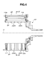
- stator 101 of the present invention For clarifying the structure of stator 101 of the present invention, the basic construction of the same will be described again with reference to Figs. 3 to 5.
- the stator core of stator 101 comprises eighteen stator teeth SP that are circumferentially arranged around common axis O of motor M at evenly spaced intervals.
- Each stator tooth SP has a rectangular parallelepiped shape and includes a plurality of pressed out I-shaped flat magnetic steel plates that are closely aligned along common axis O intimately contacting to one another.
- the stator core has a waterwheel shape that has eighteen teeth (SP) that are circumferentially arranged about common axis O.
- Each stator tooth SP has a coil 117 that is put therearound making round-trips in a direction parallel with common axis O. The shape of coil 117 will be understood from Figs. 9A and 9B.
- stator core of the stator 101 for providing the stator core with a satisfied rigidity against a marked torque applied thereto.
- each connecting ring plate 202A comprises an annular inner base portion 202Aa and eighteen finger portions 202Ab that radially extend outward from annular inner base portion 202Aa.
- Each connecting ring plate 202A is preferably made of a magnetic steel plate. In this case, the electromagnetic characteristic of stator 101 is increased. However, if desired, non-magnetic metal, such as aluminum, stainless steel or the like may be used for the connecting ring plate 202A.
- non-magnetic metal such as aluminum, stainless steel or the like may be used for the connecting ring plate 202A.
- a unit including the eighteen stator teeth SP and the four ring plates 202A installed in the stator teeth SP are all fastened to one another between the supporting brackets 118 and 113.
- a plastic molding is applied to the same, so that the stator core including the four ring plates 202A, two supporting brackets 113 and 118, bolts 119 and nuts 119a are all embedded in the molded plastic 120.
- stator 101 under rotation of outer and inner rotors OR and IR, a certain torque is applied to stator 101 in a direction to induce a deformation or inclination of the stator teeth SP.
- provision of the four connecting ring plates 202A that are tightly installed in the stator teeth SP exhibits a high resistance against the deformation or inclination of stator teeth SP, as is understood from the drawing. That is, in the present invention, in addition to bolts 119 and nuts 119a, the four connecting ring plates 202A are used for tightly coupling the stator teeth SP.
- undesired deformation or inclination of stator teeth SP is suppressed or at least minimized.
- FIG. 8 there is shown another connecting ring plate 202B. Also in this case, at least one connecting ring plate 202B is used in the above-mentioned manner.
- the connecting ring plate 202B comprises an annular outer base portion 202Ba and eighteen finger portions 202Bb that radially extend inward from annular outer base portion 202Ba.
- the stator core using the ring plates 202B can exhibit a high resistance against the deformation or inclination of the stator teeth SP.
- stator 101 that includes connecting ring plates 202A of Fig. 7 and the stator 101 that includes connecting ring plates 202B of Fig. 8
- fitting of coils 117 to the stator teeth SP can be easily achieved because the ring plates 202A and 202B have each one radial end open.
- each coil 117 is pre-shaped so as to have a rectangular opening that matches with the shape of the stator tooth SP, and when the stator teeth SP are properly assembled in the above-mentioned manner, each pre-shaped coil 117 is put on the corresponding stator tooth SP from the open side of the connecting ring plate 202A or 202B.
- each coil 117A is inserted axially over the corresponding stator tooth SP in the direction of the arrow "X", that is, in parallel with common axis O, and then open ends 117Aa of coil 117A are coupled to complete the coil 117A.
- each stator tooth SP including the connecting ring plates 202A or 202B has a radially leading end tapered, the work for putting the pre-shaped coil 117 (see Figs. 9A and 9B) onto the corresponding stator tooth SP is much easily achieved.
- auxiliary stator members 223 are circumferentially arranged at a cylindrical outer surface of the stator 101.
- each auxiliary stator member 223 comprises a non-magnetic metal base rod 221 embedded in the molded plastic zone and two magnetic metal rods 222 that are embedded in the molded plastic zone and connected to front and rear stator teeth SP.
Landscapes
- Engineering & Computer Science (AREA)
- Mechanical Engineering (AREA)
- Power Engineering (AREA)
- Chemical & Material Sciences (AREA)
- Combustion & Propulsion (AREA)
- Transportation (AREA)
- General Engineering & Computer Science (AREA)
- Iron Core Of Rotating Electric Machines (AREA)
Abstract
Description
Claims (10)
- A stator (101) for use in a two rotor single stator type electric motor (M) in which inner and outer rotors (IR, OR) are rotated independently within and around the stator (101) upon application of current to the stator, the stator (101) comprising:a stator core including a plurality of stator teeth (SP) that are circumferentially arranged around a common axis (O), each stator tooth (SP) including a plurality of flat magnetic steel plates that are aligned along the common axis (O) while intimately and closely contacting to one another; andat least one connecting ring plate (202A, 202B) coaxially installed in the stator core in such a manner that the ring plate (202A, 202B) is intimately put between adjacent two of the flat magnetic steel plates of each stator tooth, the ring plate (202A, 202B) being of an endless annular member.
- A stator as claimed in Claim 1, in which the connecting ring plate (202A) comprises:an annular inner base portion (202Aa) ; anda plurality of finger portions 202Ab) that radially extend outward from the annular inner base portion.
- A stator as claimed in Claim 1, in which the connecting ring plate (202B) comprises:an annular outer base portion (202Ba); anda plurality of finger portions (202Bb) that radially extend inward from the annular outer base portion.
- A stator as claimed in Claim 1, in which the connecting ring plate (202A, 202B) is constructed of a magnetic steel plate.
- A stator as claimed in Claim 1, in which the connecting ring plate (202A, 202B) is constructed of a non-magnetic metal.
- A stator as claimed in Claim 1, in which each stator tooth (SP) has a rectangular cross section.
- A stator as claimed in Claim 6, in which the rectangular cross section is tapered at its leading end.
- A stator as claimed in Claim 1, in which each stator tooth (SP) is equipped at a radially leading end thereof with an auxiliary stator member (222) that is constructed of a magnetic steel.
- A stator as claimed in Claim 8, in which the auxiliary stator member (222) of one stator tooth (SP) and the auxiliary stator member (222) of an adjacent stator tooth (SP) are separated by a non-magnetic metal member (221) that is arranged between the two stator teeth (SP).
- A stator (101) for use in a two rotor single stator type electric motor (M) in which inner and outer rotors (IR, OR) are rotated independently within and around the stator (101) upon application of a compound electric current to the stator (101), the stator (101) comprising:a stator core including a plurality of stator teeth (SP) that are circumferentially arranged around a common axis (O), each stator tooth (SP) including a plurality of flat magnetic steel plates that are aligned along the common axis (O) while intimately and closely contacting to one another;at least one connecting ring plate (202A, 202B) coaxially installed in the stator core in such a manner that the ring plate (202A, 202B) is intimately put between adjacent two of the flat magnetic steel plates of each stator tooth, the ring plate (202A, 202B) being of an endless annular member;a plurality of coils (117) put around the stator teeth (SP) respectively;two supporting brackets (118, 113) between which the stator teeth (SP) of the stator core are sandwiched;fastening members (119, 119a) that fasten the two supporting brackets (118, 113) to tightly and intimately connect the magnetic steel plates of each stator tooth (SP) to one another; anda molded plastic (120) that embeds therein the stator core, the connecting ring plate (202A, 202B), the coils (117), the two supporting brackets (118, 113) and the fastening members (119, 119a) thereby to constitute a cylindrical structure.
Applications Claiming Priority (2)
| Application Number | Priority Date | Filing Date | Title |
|---|---|---|---|
| JP2003101339 | 2003-04-04 | ||
| JP2003101339A JP2004312845A (en) | 2003-04-04 | 2003-04-04 | Stator for motor |
Publications (3)
| Publication Number | Publication Date |
|---|---|
| EP1465326A2 true EP1465326A2 (en) | 2004-10-06 |
| EP1465326A3 EP1465326A3 (en) | 2004-12-15 |
| EP1465326B1 EP1465326B1 (en) | 2006-01-25 |
Family
ID=32844716
Family Applications (1)
| Application Number | Title | Priority Date | Filing Date |
|---|---|---|---|
| EP04008234A Expired - Lifetime EP1465326B1 (en) | 2003-04-04 | 2004-04-05 | Stator of two rotor single stator type electric motor |
Country Status (5)
| Country | Link |
|---|---|
| US (1) | US7259493B2 (en) |
| EP (1) | EP1465326B1 (en) |
| JP (1) | JP2004312845A (en) |
| CN (1) | CN100380789C (en) |
| DE (1) | DE602004000342T2 (en) |
Cited By (9)
| Publication number | Priority date | Publication date | Assignee | Title |
|---|---|---|---|---|
| US7154193B2 (en) | 2004-09-27 | 2006-12-26 | General Electric Company | Electrical machine with double-sided stator |
| US7154191B2 (en) | 2004-06-30 | 2006-12-26 | General Electric Company | Electrical machine with double-sided rotor |
| US7154192B2 (en) | 2004-09-27 | 2006-12-26 | General Electric Company | Electrical machine with double-sided lamination stack |
| US7548008B2 (en) | 2004-09-27 | 2009-06-16 | General Electric Company | Electrical machine with double-sided lamination stack |
| US7692357B2 (en) | 2004-12-16 | 2010-04-06 | General Electric Company | Electrical machines and assemblies including a yokeless stator with modular lamination stacks |
| US7839048B2 (en) | 2004-09-27 | 2010-11-23 | General Electric Company | Electrical machine with double-sided stator |
| US9431884B2 (en) | 2013-03-26 | 2016-08-30 | Caterpillar Inc. | Dual rotor switched reluctance machine |
| CN115467999A (en) * | 2021-06-11 | 2022-12-13 | 浙江三花汽车零部件有限公司 | Fluid management device |
| CN115667716A (en) * | 2020-03-31 | 2023-01-31 | 固瑞克明尼苏达有限公司 | Pumps with high torque drives |
Families Citing this family (55)
| Publication number | Priority date | Publication date | Assignee | Title |
|---|---|---|---|---|
| JP4239923B2 (en) * | 2004-08-02 | 2009-03-18 | 日産自動車株式会社 | Electric power transmission device |
| JP4260799B2 (en) * | 2005-12-02 | 2009-04-30 | 本田技研工業株式会社 | Electric motor and method for driving electric motor |
| JP4576363B2 (en) * | 2006-08-09 | 2010-11-04 | 本田技研工業株式会社 | Auxiliary drive |
| CN101262162B (en) * | 2007-03-06 | 2011-04-06 | 桂林吉星电子等平衡动力有限公司 | Fuel engine servo loading device and its dynamic optimization operation control method |
| CN101257243B (en) * | 2007-03-01 | 2012-06-27 | 桂林吉星电子等平衡动力有限公司 | Fuel engine servo-loading unit and optimum efficiency operation control method |
| US7633199B2 (en) * | 2007-08-03 | 2009-12-15 | Hiwin Mikrosystem Corp. | Direct drive torque motor |
| US7839049B2 (en) * | 2007-11-29 | 2010-11-23 | General Electric Company | Stator and stator tooth modules for electrical machines |
| JP4505521B2 (en) * | 2008-07-09 | 2010-07-21 | 本田技研工業株式会社 | Power equipment |
| US20120025644A1 (en) * | 2009-04-21 | 2012-02-02 | Toyota Jidosha Kabushiki Kaisha | Electric motor having speed change function |
| US8258737B2 (en) * | 2009-06-24 | 2012-09-04 | Casey John R | Electric machine with non-coaxial rotors |
| CN101992687A (en) * | 2009-08-25 | 2011-03-30 | 北京汽车研究总院有限公司 | Electric infinitely variable speed system and hybrid power vehicle |
| DK2333325T3 (en) * | 2009-11-26 | 2015-08-24 | Siemens Ag | Brake system, wind turbine generator and |
| BR112012024208A2 (en) * | 2010-03-26 | 2020-08-11 | Honda Motor Co., Ltd. | vehicle equipped with a drive motor |
| EP2567450A4 (en) | 2010-05-04 | 2018-01-17 | Remy Technologies, LLC | Electric machine cooling system and method |
| US8659191B2 (en) | 2010-05-18 | 2014-02-25 | Remy Technologies, Llc | Sleeve member for an electric machine |
| DE112011101912T5 (en) | 2010-06-04 | 2013-03-28 | Remy Technologies Llc. | Cooling system and method for an electric machine |
| JP2013528353A (en) | 2010-06-08 | 2013-07-08 | レミー テクノロジーズ リミテッド ライアビリティー カンパニー | Electromechanical cooling system and method |
| US8456046B2 (en) | 2010-06-08 | 2013-06-04 | Remy Technologies, Llc | Gravity fed oil cooling for an electric machine |
| US8519581B2 (en) | 2010-06-08 | 2013-08-27 | Remy Technologies, Llc | Electric machine cooling system and method |
| US8269383B2 (en) | 2010-06-08 | 2012-09-18 | Remy Technologies, Llc | Electric machine cooling system and method |
| US8482169B2 (en) | 2010-06-14 | 2013-07-09 | Remy Technologies, Llc | Electric machine cooling system and method |
| US8614538B2 (en) | 2010-06-14 | 2013-12-24 | Remy Technologies, Llc | Electric machine cooling system and method |
| US8446056B2 (en) | 2010-09-29 | 2013-05-21 | Remy Technologies, Llc | Electric machine cooling system and method |
| US8593021B2 (en) | 2010-10-04 | 2013-11-26 | Remy Technologies, Llc | Coolant drainage system and method for electric machines |
| US8492952B2 (en) | 2010-10-04 | 2013-07-23 | Remy Technologies, Llc | Coolant channels for electric machine stator |
| US8395287B2 (en) | 2010-10-04 | 2013-03-12 | Remy Technologies, Llc | Coolant channels for electric machine stator |
| US8508085B2 (en) | 2010-10-04 | 2013-08-13 | Remy Technologies, Llc | Internal cooling of stator assembly in an electric machine |
| US8648506B2 (en) | 2010-11-09 | 2014-02-11 | Remy Technologies, Llc | Rotor lamination cooling system and method |
| US8742641B2 (en) | 2010-11-23 | 2014-06-03 | Remy Technologies, L.L.C. | Concentric motor power generation and drive system |
| US8497608B2 (en) | 2011-01-28 | 2013-07-30 | Remy Technologies, Llc | Electric machine cooling system and method |
| WO2012145302A2 (en) | 2011-04-18 | 2012-10-26 | Remy Technologies, Llc | Electric machine module cooling system and method |
| US8692425B2 (en) | 2011-05-10 | 2014-04-08 | Remy Technologies, Llc | Cooling combinations for electric machines |
| US8803380B2 (en) | 2011-06-03 | 2014-08-12 | Remy Technologies, Llc | Electric machine module cooling system and method |
| US9041260B2 (en) | 2011-07-08 | 2015-05-26 | Remy Technologies, Llc | Cooling system and method for an electronic machine |
| US8803381B2 (en) | 2011-07-11 | 2014-08-12 | Remy Technologies, Llc | Electric machine with cooling pipe coiled around stator assembly |
| US8546982B2 (en) | 2011-07-12 | 2013-10-01 | Remy Technologies, Llc | Electric machine module cooling system and method |
| US9048710B2 (en) | 2011-08-29 | 2015-06-02 | Remy Technologies, Llc | Electric machine module cooling system and method |
| US8975792B2 (en) | 2011-09-13 | 2015-03-10 | Remy Technologies, Llc | Electric machine module cooling system and method |
| AR083135A1 (en) * | 2011-10-05 | 2013-02-06 | Ind Metalurgicas Pescarmona S A I C Y F | SYNCHRONIC WIND GENERATOR |
| US9099900B2 (en) | 2011-12-06 | 2015-08-04 | Remy Technologies, Llc | Electric machine module cooling system and method |
| US9331543B2 (en) | 2012-04-05 | 2016-05-03 | Remy Technologies, Llc | Electric machine module cooling system and method |
| US10069375B2 (en) | 2012-05-02 | 2018-09-04 | Borgwarner Inc. | Electric machine module cooling system and method |
| US9000644B2 (en) * | 2012-06-05 | 2015-04-07 | Remy Technologies, L.L.C. | Concentric motor power generation and drive system |
| CA2830944C (en) | 2012-10-24 | 2019-10-22 | Enedym Inc. | Double-rotor switched reluctance machine |
| US10411532B2 (en) | 2013-10-27 | 2019-09-10 | Moovee Innovations Inc. | Software-defined electric motor |
| DE102013112605A1 (en) * | 2013-11-15 | 2015-05-21 | Dr. Ing. H.C. F. Porsche Aktiengesellschaft | Drive module for a vehicle |
| DE102014109177A1 (en) * | 2014-07-01 | 2016-01-07 | Dr. Ing. H.C. F. Porsche Aktiengesellschaft | Arrangement of an electric machine and one of these downstream transmission |
| US9621014B2 (en) | 2014-07-31 | 2017-04-11 | Mcmaster University | Torque ripple and radial force reduction in double-rotor switched reluctance machines |
| FR3027744B1 (en) * | 2014-10-23 | 2016-12-02 | Mmt Sa | POLYPHASE MOTOR HAVING ALTERNANCE OF PERMANENT MAGNETS AND HIGHLIGHTS |
| CN104875597B (en) * | 2015-05-22 | 2017-09-05 | 江苏大学 | A kind of engine start/stop system and its method of work based on double-rotor machine |
| US9638292B1 (en) * | 2015-10-27 | 2017-05-02 | Schaeffler Technologies AG & Co. KG | CVT differential |
| KR101755492B1 (en) * | 2015-12-04 | 2017-07-10 | 현대자동차 주식회사 | Stator assembly structure for drive motor of hybrid electric vehicle |
| CN106369115A (en) * | 2016-11-21 | 2017-02-01 | 郭克亚 | Planetary dual-rotor driving device |
| CN106849570A (en) * | 2017-03-03 | 2017-06-13 | 福建亚南电机有限公司 | A kind of permanent magnetism double stators and double rotors high torque density wheel hub motor |
| EP4387058A1 (en) | 2022-12-13 | 2024-06-19 | GE Energy Power Conversion Technology Ltd | Rotating electrical machine, set of such machines, and associated boat and rolling mill |
Family Cites Families (22)
| Publication number | Priority date | Publication date | Assignee | Title |
|---|---|---|---|---|
| US2323114A (en) * | 1942-02-26 | 1943-06-29 | Gen Motors Corp | Pole piece assembly |
| US2871384A (en) * | 1955-09-14 | 1959-01-27 | George W Baker | Stator constructions for synchronous hysteresis motors |
| US3469136A (en) * | 1968-03-21 | 1969-09-23 | Lucas Industries Ltd | Laminated stators for dynamo electric machines |
| US3671787A (en) * | 1971-08-16 | 1972-06-20 | Ibm | Laminated dynamoelectric machine having nonmagnetic lamina for structural support |
| JPH0522920A (en) * | 1990-09-28 | 1993-01-29 | Aisin Seiki Co Ltd | Linear actuator |
| JPH06105488A (en) | 1992-07-23 | 1994-04-15 | Hitachi Ltd | AC generator for automobile |
| DE9313958U1 (en) * | 1992-10-14 | 1993-11-25 | Yun, Ja Dong, Seoul | Electric generator for small drive power |
| NZ276595A (en) * | 1993-11-19 | 1997-11-24 | Richard A Campfield | Windscreen repair kit; method for repairing windscreen crack over six inches long using resin or resins of defined viscosity |
| US5793136A (en) * | 1996-06-05 | 1998-08-11 | Redzic; Sabid | Differential motor/generator apparatus |
| US5799387A (en) * | 1996-06-05 | 1998-09-01 | L.H. Carbide Corpordation | Lamina stack having a plurality of outer perimeter configurations and an apparatus and method for manufacturing said stack |
| JPH1189130A (en) * | 1997-09-08 | 1999-03-30 | Minebea Co Ltd | Motor construction |
| US6191510B1 (en) * | 1997-12-19 | 2001-02-20 | 3M Innovative Properties Company | Internally damped stator, rotor, and transformer and a method of making |
| JPH11332140A (en) * | 1998-05-08 | 1999-11-30 | Sankyo Seiki Mfg Co Ltd | Armature structure for radial rib winding type rotating electric machine |
| JPH11341757A (en) * | 1998-05-21 | 1999-12-10 | Toyota Motor Corp | Electric motor, power transmission device, and hybrid vehicle |
| JPH11346446A (en) * | 1998-06-01 | 1999-12-14 | Hitachi Ltd | Rotating electric machine stator |
| JP3559891B2 (en) | 1998-06-22 | 2004-09-02 | 日産自動車株式会社 | Cooling structure of multilayer motor |
| US6225725B1 (en) * | 1999-02-08 | 2001-05-01 | Itoh Electric Co. Ltd. | Manufacturing process of a divided type stator |
| JP4040202B2 (en) | 1999-04-01 | 2008-01-30 | 三菱電機株式会社 | Stator core for vehicle alternator and method for manufacturing stator core for vehicle alternator |
| JP3580194B2 (en) * | 1999-10-04 | 2004-10-20 | 日産自動車株式会社 | Assembly structure of rotating electric machine |
| JP3496595B2 (en) | 1999-10-27 | 2004-02-16 | 日産自動車株式会社 | Rotating electric machine |
| US6448685B1 (en) * | 2000-09-28 | 2002-09-10 | General Electric Company | Stator core assembly |
| JP3614409B2 (en) * | 2002-03-25 | 2005-01-26 | 日産自動車株式会社 | Hybrid transmission |
-
2003
- 2003-04-04 JP JP2003101339A patent/JP2004312845A/en not_active Withdrawn
-
2004
- 2004-04-02 CN CNB2004100333538A patent/CN100380789C/en not_active Expired - Fee Related
- 2004-04-02 US US10/815,865 patent/US7259493B2/en not_active Expired - Fee Related
- 2004-04-05 DE DE602004000342T patent/DE602004000342T2/en not_active Expired - Fee Related
- 2004-04-05 EP EP04008234A patent/EP1465326B1/en not_active Expired - Lifetime
Cited By (10)
| Publication number | Priority date | Publication date | Assignee | Title |
|---|---|---|---|---|
| US7154191B2 (en) | 2004-06-30 | 2006-12-26 | General Electric Company | Electrical machine with double-sided rotor |
| US7830063B2 (en) | 2004-06-30 | 2010-11-09 | General Electric Company | Electrical machine with double-sided rotor |
| US7154193B2 (en) | 2004-09-27 | 2006-12-26 | General Electric Company | Electrical machine with double-sided stator |
| US7154192B2 (en) | 2004-09-27 | 2006-12-26 | General Electric Company | Electrical machine with double-sided lamination stack |
| US7548008B2 (en) | 2004-09-27 | 2009-06-16 | General Electric Company | Electrical machine with double-sided lamination stack |
| US7839048B2 (en) | 2004-09-27 | 2010-11-23 | General Electric Company | Electrical machine with double-sided stator |
| US7692357B2 (en) | 2004-12-16 | 2010-04-06 | General Electric Company | Electrical machines and assemblies including a yokeless stator with modular lamination stacks |
| US9431884B2 (en) | 2013-03-26 | 2016-08-30 | Caterpillar Inc. | Dual rotor switched reluctance machine |
| CN115667716A (en) * | 2020-03-31 | 2023-01-31 | 固瑞克明尼苏达有限公司 | Pumps with high torque drives |
| CN115467999A (en) * | 2021-06-11 | 2022-12-13 | 浙江三花汽车零部件有限公司 | Fluid management device |
Also Published As
| Publication number | Publication date |
|---|---|
| US7259493B2 (en) | 2007-08-21 |
| CN1538597A (en) | 2004-10-20 |
| EP1465326A3 (en) | 2004-12-15 |
| US20040195929A1 (en) | 2004-10-07 |
| EP1465326B1 (en) | 2006-01-25 |
| DE602004000342D1 (en) | 2006-04-13 |
| JP2004312845A (en) | 2004-11-04 |
| DE602004000342T2 (en) | 2006-07-27 |
| CN100380789C (en) | 2008-04-09 |
Similar Documents
| Publication | Publication Date | Title |
|---|---|---|
| EP1465326B1 (en) | Stator of two rotor single stator type electric motor | |
| US6838790B2 (en) | Stator of two rotor single stator type electric motor | |
| US6864607B2 (en) | Driving apparatus for vehicle | |
| USRE38017E1 (en) | Hybrid vehicle powertrain | |
| CN101678753B (en) | Hybrid drive device | |
| EP3736952B1 (en) | Drive device for vehicles | |
| CN1581638A (en) | Rotating machine | |
| EP1093958A2 (en) | Vehicle drive unit | |
| US20230041635A1 (en) | Drive unit and drive assembly | |
| JP4029817B2 (en) | Magnetic circuit structure of rotating electrical machine | |
| JP3627337B2 (en) | Electric vehicle drive | |
| US7220207B2 (en) | Differential apparatus | |
| JP3693034B2 (en) | Coaxial rotating electric machine | |
| JP4111117B2 (en) | Rotation machine rotation sensor arrangement structure | |
| JP4082126B2 (en) | Outer rotor support bearing mounting structure for multi-axis multi-layer motor | |
| JP2004312800A (en) | Stator structure of multi-axis multilayer motor | |
| JP4016931B2 (en) | Multi-axis multilayer motor | |
| JP3885755B2 (en) | Stator structure of multi-axis multilayer motor | |
| JP4135627B2 (en) | Stator structure of rotating electrical machine | |
| JP2005168205A (en) | Stator core structure of rotating electrical machine | |
| JP3622748B2 (en) | Hybrid transmission | |
| JP3928546B2 (en) | Hybrid transmission | |
| JP4111124B2 (en) | Stator structure of rotating electrical machine | |
| JP2004336905A (en) | Motor rotor structure | |
| JP2005124356A (en) | Magnetic circuit structure of rotating electrical machine |
Legal Events
| Date | Code | Title | Description |
|---|---|---|---|
| PUAI | Public reference made under article 153(3) epc to a published international application that has entered the european phase |
Free format text: ORIGINAL CODE: 0009012 |
|
| 17P | Request for examination filed |
Effective date: 20040405 |
|
| AK | Designated contracting states |
Kind code of ref document: A2 Designated state(s): AT BE BG CH CY CZ DE DK EE ES FI FR GB GR HU IE IT LI LU MC NL PL PT RO SE SI SK TR |
|
| AX | Request for extension of the european patent |
Extension state: AL HR LT LV MK |
|
| PUAL | Search report despatched |
Free format text: ORIGINAL CODE: 0009013 |
|
| AK | Designated contracting states |
Kind code of ref document: A3 Designated state(s): AT BE BG CH CY CZ DE DK EE ES FI FR GB GR HU IE IT LI LU MC NL PL PT RO SE SI SK TR |
|
| AX | Request for extension of the european patent |
Extension state: AL HR LT LV MK |
|
| GRAP | Despatch of communication of intention to grant a patent |
Free format text: ORIGINAL CODE: EPIDOSNIGR1 |
|
| AKX | Designation fees paid |
Designated state(s): DE FR GB |
|
| GRAS | Grant fee paid |
Free format text: ORIGINAL CODE: EPIDOSNIGR3 |
|
| GRAA | (expected) grant |
Free format text: ORIGINAL CODE: 0009210 |
|
| AK | Designated contracting states |
Kind code of ref document: B1 Designated state(s): DE FR GB |
|
| REG | Reference to a national code |
Ref country code: GB Ref legal event code: FG4D |
|
| REF | Corresponds to: |
Ref document number: 602004000342 Country of ref document: DE Date of ref document: 20060413 Kind code of ref document: P |
|
| ET | Fr: translation filed | ||
| PLBE | No opposition filed within time limit |
Free format text: ORIGINAL CODE: 0009261 |
|
| STAA | Information on the status of an ep patent application or granted ep patent |
Free format text: STATUS: NO OPPOSITION FILED WITHIN TIME LIMIT |
|
| 26N | No opposition filed |
Effective date: 20061026 |
|
| PGFP | Annual fee paid to national office [announced via postgrant information from national office to epo] |
Ref country code: DE Payment date: 20080411 Year of fee payment: 5 Ref country code: FR Payment date: 20080312 Year of fee payment: 5 |
|
| PGFP | Annual fee paid to national office [announced via postgrant information from national office to epo] |
Ref country code: GB Payment date: 20080409 Year of fee payment: 5 |
|
| GBPC | Gb: european patent ceased through non-payment of renewal fee |
Effective date: 20090405 |
|
| REG | Reference to a national code |
Ref country code: FR Ref legal event code: ST Effective date: 20091231 |
|
| PG25 | Lapsed in a contracting state [announced via postgrant information from national office to epo] |
Ref country code: DE Free format text: LAPSE BECAUSE OF NON-PAYMENT OF DUE FEES Effective date: 20091103 |
|
| PG25 | Lapsed in a contracting state [announced via postgrant information from national office to epo] |
Ref country code: FR Free format text: LAPSE BECAUSE OF NON-PAYMENT OF DUE FEES Effective date: 20091222 Ref country code: GB Free format text: LAPSE BECAUSE OF NON-PAYMENT OF DUE FEES Effective date: 20090405 |