Technical Field
-
The present invention relates to a magnetic head device, and it
relates in particular to a magnetic head device that can reduce the thickness
of an information recording/ reproducing apparatus.
Background Art
-
A magneto-optical recording/ reproducing apparatus includes an
optical head on one side of a magneto-optical disk, which serves as an
information recording medium, that is rotated by a driving mechanism for
rotating the disk, and a magnetic head that is opposed to the optical head on
the other side of the magneto-optical disk; the optical head emits a light
beam for irradiating a magneto―optical recording layer of the information
recording medium, and the magnetic head applies an external magnetic field
to the magneto-optical recording layer. The magneto―optical recording/reproducing
apparatus applies a magnetic field, whose direction is modulated
in accordance with the information signal to be recorded, from the magnetic
head onto the magneto―optical recording layer of the rotating
magneto―optical disk, while it focuses and irradiates a light beam emitted
from the optical head onto the magneto-optical recording layer.
-
This light beam irradiation heats a portion of the magneto-optical
recording layer to a temperature above the Curie temperature, so that this
portion loses its coercive force. After this portion has been magnetized in the
direction of the magnetic field applied by the magnetic head, this portion is
moved relative to the light beam by rotation of the magneto-optical disk, so
that this portion is cooled below the Curie temperature and the
magnetization direction is fixed. Thus, an information signal is recorded in
the magneto-optical recording layer.
-
Since the magneto-optical disk is rotated, the surface thereof is likely
to vibrate. Thus, in the magnetic head, a head main body is provided at a
free end of a cantilevered supporting member that can move in the direction
of surface vibration of the magneto-optical disk. This head main body
includes a slider that is provided with a magnetic field applying portion and
glides in contact over the magneto―optical disk or floats keeping a slight
distance from the magneto-optical disk.
-
The magnetic head device takes a first position in which the slider
glides in contact over or floats on the magneto―optical disk so that the slider
and the magneto-optical disk come close to each other in a recording state,
and a second position in which the free end of the supporting member and the
head main body are spaced away from the magneto-optical disk by a
magnetic head lifting/ lowering device of the magnetic head device so as to be
in a reproducing state.
-
A conventional magnetic head device is described in, for example, JP
10(1998)-802882 A (JP Patent Application No. 10(1998)-505847).
-
The following is a description of the conventional magnetic head
device, with reference to FIGs. 10 to 13. FIG. 10 is a plan view of an
example of the conventional magnetic head device. As shown in the figure,
an XYZ three―dimensional rectangular coordinate system is defined such
that an X axis indicates a radial direction of an magneto-optical disk 1, a Y
axis indicates a tangential direction thereof, and a Z axis indicates a normal
direction thereof. FIG. 11 is a sectional side view of the magnetic head
device shown in FIG. 10, taken along a line S-S and seen from an arrow
direction, in the first position (recording state). FIG. 12 is a sectional side
view of the magnetic head device shown in FIG. 10, taken along the line S-S
and seen from the arrow direction, in the second position (reproducing state).
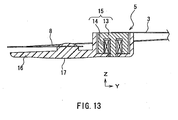
FIG. 13 is a sectional side view of a head main body of the magnetic head
device shown in FIG. 10.
-
The conventional magnetic head device includes a head main body 5,
a thin supporting member 6 for pressing a sliding portion 17 of the head main
body 5 against the surface of the magneto―optical disk 1, and a fastening
portion 7 to which one end of the supporting member 6 is attached. The
head main body 5 is attached to the other end (free end) of the cantilevered
supporting member 6 by gluing, welding or the like.
-
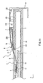
As shown in FIG. 13, the head main body 5 includes a magnetic head
element 15 formed by attaching a wound coil 14 to a central magnetic pole of
an E-shaped magnetic core 13 made of a soft magnetic material such as
ferrite and a slider 16 that has the sliding portion 17 gliding directly in
contact over the magneto-optical disk 1 and is made of a resin with excellent
sliding characteristics, for example, polyphenylene sulfide or liquid crystal
polymer. This magnetic head element 15 is attached integrally to the slider
16 by glue―fixing or integral molding of a resin.
-
The supporting member 6 is formed with a thin plate made of a
material such as SUS304 or BeCu. The supporting member 6 has a first
spring system 10 serving as a first elastic deformable portion that has one
end fastened to the fastening portion 7 and is provided for following surface
vibration of the magneto―optical disk 1 and applying a load to the head main
body 5 in the direction of the magneto-optical disk 1 in the first position for
recording on the magneto-optical disk 1, an intermediate portion 9 that is
extended from the first spring system 10 while being inclined with respect to
this first spring system 10 at a predetermined angle so as not to interfere
with a cartridge 2 and formed to be a rigid body by being provided with draw
ribs 11 formed by draw forming on both sides in the width direction, and a
second spring system 8 serving as a second elastic deformable portion that is
extended from the intermediate portion 9 and provided for following the
surface shape of the magneto―optical disk 1.
-
A flexible printed board 3 has one end adhered to the head main body
5 and the other end adhered to the vicinity of the fastening portion 7 of the
supporting member 6. One end of the flexible printed board 3 is soldered to
both ends of lead wires of the coil 14, while the other end is connected to a
magnetic head driving circuit, which is not shown in the figure.
-
The fastening portion 7 is made of a metal plate of such as iron or
stainless steel. The fastening portion 7 fastens one end of the supporting
member 6 and is attached in a freely rotatable manner to a joint member 19
for joining the optical head, which is not shown, and the magnetic head 4 via
a shaft 18 and forced against the side of the magneto―optical disk 1 by a
spring or the like, which is not shown in the figure.
-
The following is a description of a magnetic head lifting/ lowering
device for moving the head main body 5 from the first position to the second
position. A lifting mechanism 220 is disposed between the magnetic head 4
and a holder 23 for holding the cartridge 2 in which the magneto-optical disk
1 is received, and is attached in a freely rotatable manner around a lifting/lowering
rotation shaft 226 provided in the holder 23. A sliding member 24
is attached to the holder 23 and can slide in a Y direction in FIG. 10 by a
lifting/ lowering driving portion 25, which is constituted by a motor, a gear etc.
and attached to the holder 23. In a part of the sliding member 24, an
inclined surface 24a whose height in a Z―axis direction varies is formed along
the Y―axis direction. The lifting mechanism 220 is forced by an elastic
member such as a spring (not shown) so that its lower surface presses the
inclined surface 24a of the sliding member 24. In this manner, a cam
mechanism is formed in a portion where the inclined surface 24a of the
sliding member 24 contacts the lifting mechanism 220. The lifting
mechanism 220 and the sliding member 24 are formed with a thin resin plate
or a thin metal plate made of stainless steel or iron, for example. In a
portion of the lifting mechanism 220 where it contacts the magnetic head 4
when the head main body 5 is moved to the second position, a curved lifting/lowering
portion 221 is provided.
-
In the first position (recording position) of the head main body 5,
namely, in the state that the sliding portion 17 glides in contact over the
magneto―optical disk 1 as shown in FIG. 11, the first spring system 10 for
applying the load in the direction that the head main body 5 is brought in
contact with the magneto-optical disk 1 and the second spring system 8 that
is displaced according to the surface vibration of the magneto-optical disk 1
and the change in surface shape thereof cause the sliding portion 17 to follow
the surface vibration of the magneto-optical disk 1 and the change in surface
shape thereof and glide in contact over the disk constantly.
-
In this case, the lifting/lowering portion 221 of the lifting mechanism
220 is retracted on the side of the magneto-optical disk 1 so as not to contact
the magnetic head 4.
-
The head main body 5 is moved from the first position (recording
position) to the second position (reproducing position) as follows. The lifting/lowering
driving portion 25 drives the sliding member 24 to slide in the
direction indicated by an arrow a shown in FIG. 10. The inclined surface
24a constituting the cam mechanism contacts the lower surface of the lifting
mechanism 220 and lifts the lifting mechanism 220 so as to rotate the lifting
mechanism 220 around the lifting/ lowering rotation shaft 226, so that the
lifting/lowering portion 221 moves away from the magneto―optical disk 1.
Then, the lifting/ lowering portion 221 contacts the lower surface (the surface
on the side of the magneto―optical disk 1) of the intermediate portion 9 of the
magnetic head 4 so as to deform the first spring system 10 elastically, so that
the head main body 5 is moved away from the magneto-optical disk 1 and
lifted up to the position at which the head main body 5 is spaced from the
cartridge 2 by a gap H2, namely, the second position. At the time when the
head main body 5 is moved away from the magneto―optical disk 1, an end
portion (P1) of the first spring system 10 on the side of the fastening portion 7
serves as the center of rotation.
-
Accompanying the recent popularization of small-size portable
appliances, apparatus have become thinner and thinner, and the thickness of
the magnetic head device 4 and the height H3 from the upper surface of the
cartridge 2 to the fastening portion 7 have been reduced. However, in the
structure of the conventional magnetic head and the magnetic head lifting/lowering
device described above, the displacement amount of the lifting/lowering
portion 221 has to be increased for moving the head main body 5 to
the second position. In other words, in order to space the head main body 5
sufficiently away from the magneto―optical disk 1 in the second position, it is
necessary to space the lifting/lowering portion 221 itself considerably away
from the cartridge 2 (see a height H4 in FIG. 12). Consequently, the
supporting member 6, in particular, a bent portion connecting the first spring
system 10 and the intermediate portion 9 protrudes greatly beyond the
fastening portion 7 (in other words, a height H1 of the protruding portion
from the upper surface of the cartridge 2 is great). As a result, there has
been a problem in that the magneto―optical recording/ reproducing apparatus
cannot be made thinner.
Disclosure of Invention
-
It is an object of the present invention to solve the conventional
problem described above and to provide a magnetic head device that can
reduce the thickness of an information recording/ reproducing apparatus.
-
In order to achieve the above-mentioned object, a first magnetic head
device of the present invention includes a magnetic head including a
cantilevered supporting member having one end serving as a fastened end,
the other end serving as a free end and an elastic portion between the
fastened end and the free end, and a head main body attached to the free end
of the supporting member; a first lifting/ lowering portion that is disposed on
a side of an information recording medium with respect to the supporting
member; and a second lifting/ lowering portion that is disposed on a side
opposite to the information recording medium with respect to the supporting
member and on a side of the fastened end with respect to the first lifting/lowering
portion. The magnetic head has a first position in which the head
main body is located close to or in contact with the information recording
medium so as to perform recording or reproducing and a second position in
which the head main body is away from the information recording medium.
While the first lifting/ lowering portion moves away from the information
recording medium and contacts a surface of the supporting member on a side
of the information recording medium so as to move the head main body from
the first position to the second position, the second lifting/ lowering portion
contacts a surface of the elastic portion of the supporting member on a side
opposite to the information recording medium.
-
Further a second magnetic head device of the present invention
includes a magnetic head including a cantilevered supporting member having
one end serving as a fastened end, the other end serving as a free end and an
elastic portion between the fastened end and the free end, and a head main
body attached to the free end of the supporting member; a first lifting/lowering
portion that is disposed on a side of an information recording
medium with respect to the supporting member; and a second lifting/lowering
portion that is disposed on a side opposite to the information
recording medium with respect to the supporting member and on a side of the
fastened end with respect to the first lifting/lowering portion. The magnetic
head has a first position in which the head main body is located close to or in
contact with the information recording medium so as to perform recording or
reproducing and a second position in which the head main body is away from
the information recording medium. While the first lifting/ lowering portion
moves along a longitudinal direction of the magnetic head and contacts a
surface of the supporting member on a side of the information recording
medium so as to move the head main body from the first position to the
second position, the second lifting/lowering portion contacts a surface of the
elastic portion of the supporting member on a side opposite to the information
recording medium.
Brief Description of Drawings
-
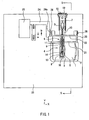
- FIG. 1 is a plan view showing a magnetic head device according to a
first embodiment of the present invention.
- FIG. 2 is a sectional side view of the magnetic head device according
to the first embodiment of the present invention, taken along a line S-S and
seen from an arrow direction in FIG. 1 when a head main body is in a first
position.
- FIG. 3 is a sectional side view of the magnetic head device according
to the first embodiment of the present invention, taken along the line S-S
and seen from the arrow direction in FIG. 1 when the head main body is in a
second position.
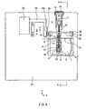
- FIG. 4 is a plan view showing a magnetic head device according to a
second embodiment of the present invention.
- FIG. 5 is a sectional side view of the magnetic head device according
to the second embodiment of the present invention, taken along a line S-S
and seen from an arrow direction in FIG. 4 when a head main body is in a
first position.
- FIG. 6 is a sectional side view of the magnetic head device according
to the second embodiment of the present invention, taken along the line S-S
and seen from the arrow direction in FIG. 4 when the head main body is in a
second position.
- FIG. 7 is a plan view showing a magnetic head device according to a
third embodiment of the present invention.
- FIG. 8 is a sectional side view of the magnetic head device according
to the third embodiment of the present invention, taken along a line S―S and
seen from an arrow direction in FIG. 7 when a head main body is in a first
position.
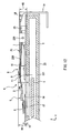
- FIG. 9 is a sectional side view of the magnetic head device according
to the third embodiment of the present invention, taken along the line S-S
and seen from the arrow direction in FIG. 7 when the head main body is in a
second position.
- FIG. 10 is a plan view showing a conventional magnetic head device.
- FIG. 11 is a sectional side view of the conventional magnetic head
device, taken along a line S-S and seen from an arrow direction in FIG. 10
when a head main body is in a first position.
- FIG. 12 is a sectional side view of the conventional magnetic head
device, taken along the line S-S and seen from the arrow direction in FIG. 10
when the head main body is in a second position.
- FIG. 13 is a sectional side view showing the head main body of the
conventional magnetic head device.
-
Best Mode for Carrying Out the Invention
-
The first and second magnetic head devices of the present invention
include a magnetic head including a cantilevered supporting member and a
head main body attached to the free end of the supporting member, a first
lifting/ lowering portion that is disposed on a side of the information
recording medium with respect to the supporting member, and a second
lifting/ lowering portion that is disposed on a side opposite to the information
recording medium with respect to the supporting member and on a side of the
fastened end with respect to the first lifting/ lowering portion.
-
In the first magnetic head device, while the first lifting/ lowering
portion moves away from the information recording medium and contacts a
surface of the supporting member on a side of the information recording
medium so as to move the head main body from the first position to the
second position, the second lifting/ lowering portion contacts a surface of the
elastic portion of the supporting member on a side opposite to the information
recording medium.
-
In this way, after the second lifting/ lowering portion contacts the
elastic portion, the head main body rotates around the contacting portion of
the second lifting/ lowering portion and the elastic portion. Therefore, the
distance from the head main body to the center of rotation can be shortened,
making it possible to further reduce the amount that the first lifting/ lowering
portion has to move in order to move the head main body to the second
position. Accordingly, it is possible to reduce the height of the farthest
portion of the magnetic head from the information recording medium when
the head main body is moved to the second position. Consequently, using
this magnetic head device, an information recording/ reproducing apparatus
can be made thinner.
-
In the above-described first magnetic head device of the present
invention, it is preferable that while the first lifting/ lowering portion moves
away from the information recording medium, the second lifting/ lowering
portion moves toward the information recording medium.
-
With this preferable structure, since the center of rotation of the head
main body at the time of moving from the first position to the second position
moves toward the information recording medium, it is possible to lower the
position of the first lifting/ lowering portion when the head main body is in
the second position. Accordingly, it is possible to reduce the height of the
magnetic head when the head main body is moved to the second position.
Consequently, using this magnetic head device, an information recording/reproducing
apparatus can be made thinner.
-
Next, in the second magnetic head device of the present invention,
while the first lifting/ lowering portion moves along a longitudinal direction of
the magnetic head and contacts a surface of the supporting member on a side
of the information recording medium so as to move the head main body from
the first position to the second position, the second lifting/ lowering portion
contacts a surface of the elastic portion of the supporting member on a side
opposite to the information recording medium.
-
In this way, after the second lifting/lowering portion contacts the
elastic portion, the head main body rotates around the contacting portion of
the second lifting/ lowering portion and the elastic portion. Therefore, the
distance from the head main body to the center of rotation can be shortened.
Accordingly, it is possible to reduce the height of the farthest portion of the
magnetic head from the information recording medium when the head main
body is moved to the second position. Consequently, using this magnetic
head device, an information recording/ reproducing apparatus can be made
thinner.
-
In the above―described first and second magnetic head devices of the
present invention, it also is preferable that the first lifting/lowering portion
and the second lifting/ lowering portion are provided in a common member.
-
With this preferable structure, a lifting/lowering mechanism can be
simplified, thus reducing the number of components.
-
Further, in the above-described first and second magnetic head
devices of the present invention, it is preferable that a surface of the second
lifting/lowering portion that is opposed to the supporting member is a curved
surface protruding toward the supporting member.
-
With this preferable structure, it is possible to reduce the frictional
force at the time when the head main body is moved in a radial direction of
the information recording medium while the head main body is in the second
position, thus achieving fast access.
-
The following is a description of embodiments of the present
invention, with reference to the accompanying drawings.
(First Embodiment)
-
FIG. 1 is a plan view of a magnetic head device in a first embodiment
of the present invention. As shown in the figure, an XYZ three-dimensional
rectangular coordinate system is defined such that an X axis indicates a
radial direction of an magneto―optical disk 1, a Y axis indicates a tangential
direction thereof, and a Z axis indicates a normal direction thereof. For the
convenience of description below, the Z-axis direction is set as a height
direction, and the side farther from the magneto―optical disk 1 is referred to
as an upper side, while the side closer thereto is referred to as a lower side.
It should be noted that the terms "height", "upper" and "lower" are irrelevant
to the orientation in which the magnetic head device is used in practice. FIG.
2 is a sectional side view of the magnetic head device shown in FIG. 1, taken
along a line S-S and seen from an arrow direction, in a first position
(recording state), and FIG. 3 is a sectional side view of the magnetic head
device shown in FIG. 1, taken along the line S―S and seen from the arrow
direction, in a second position (reproducing state). The same reference
numerals are given to components having the same functions as in the
conventional example shown in FIGs. 10 to 13, and detailed descriptions
thereof are omitted here.
-
In FIGs. 1 to 3, numeral 6 denotes a supporting member, which is
made of a thin spring material such as SUS304 or BeCu, for example. The
supporting member 6 illustrated in the present embodiment has a first spring
system 10 serving as a first elastic deformable portion that has one end
fastened to a fastening portion 7 and is provided for following surface
vibration of the magneto-optical disk 1 and applying an entire load, an
intermediate portion 9 that is extended from the first spring system 10 while
being inclined with respect to this first spring system 10 at a predetermined
angle so as not to interfere with a cartridge 2 and formed to be a rigid body by
being provided with draw ribs 11 formed by draw forming on both sides in the
width direction, and a second spring system 8 serving as a second elastic
deformable portion that is extended from the intermediate portion 9 at a
predetermined angle with respect to the intermediate portion 9 and provided
for following the surface vibration and surface shape of the magneto-optical
disk 1.
-
The fastening portion 7 is made of a metal plate of such as iron or
stainless steel. The fastening portion 7 fastens one end of the supporting
member 6, is attached to a joint member 19 for connecting a magnetic head 4
and an optical head (not shown), which is opposed to the magnetic head 4
with the magneto―optical disk 1 interposed therebetween, via a shaft 18 in
such a manner as to be freely rotatable within a YZ plane and is forced
against the side of the magneto-optical disk 1 by a spring or the like, which is
not shown in the figure.
-
As shown in FIG. 13, a head main body 5 includes a magnetic head
element 15 formed by attaching a wound coil 14 to a central magnetic pole of
an E-shaped magnetic core 13 made of a soft magnetic material such as
ferrite, and a slider 16 made of a resin with excellent sliding characteristics,
for example, polyphenylene sulfide or liquid crystal polymer. The magnetic
head element 15 is attached integrally to the slider 16 such that an open end
of the E―shaped magnetic core 13 is opposed to the magneto-optical disk 1,
thereby forming the head main body 5.
-
Numeral 17 denotes a sliding portion, which is formed integrally on a
surface of the slider 16 opposing the magneto-optical disk 1. The sliding
portion 17 has a circular arc section, thereby gliding constantly in point
contact over the magneto-optical disk 1 in a smooth manner.
-
Numeral 3 denotes a flexible printed board that is provided with
wirings for transmitting a modulation signal to the head main body 5 and has
one end adhered to the head main body 5 and the other end adhered to the
fastening portion 7. One end of the flexible printed board 3 is soldered to
both ends of lead wires of the coil 14, while the other end is connected to a
driving circuit of the magnetic head, which is not shown in the figure.
-
The head main body 5 is fastened to the side of a moving end (free
end) of the cantilevered supporting member 6 by fusing or gluing or formed in
one piece therewith by integral molding of a resin. The fastening portion
7-side-end (fastened end) of the supporting member 6 is fastened to the
fastening portion 7 by laser spot welding or the like.
-
Numeral 20 denotes a lifting mechanism formed of stainless steel,
iron or resin, for example. The lifting mechanism 20 is attached in such a
manner as to be freely rotatable within the YZ plane around a lifting/lowering
rotation shaft 26 provided in a holder 23 for holding the cartridge 2.
The lifting mechanism 20 has a first lifting/ lowering portion 21 that is
provided on the side of the head main body 5 with respect to the lifting/lowering
rotation shaft 26 and between the magnetic head 4 and the
cartridge 2, and a second lifting/lowering portion 22 that is provided between
the first lifting/lowering portion 21 and the lifting/lowering rotation shaft 26
and on the side opposite to the cartridge 2 with respect to the magnetic head
4. The first lifting/ lowering portion 21 and the second lifting/ lowering
portion 22 both extend along the X axis.
-
Numeral 24 denotes a sliding member that is formed of stainless steel,
iron or resin, for example, attached to the holder 23 in such a manner as to be
slidable in the Y―axis direction and slides by a lifting/lowering driving
portion 25, which is constituted by a motor, a gear etc.
-
In a part of the sliding member 24, an inclined surface 24a whose
height in the Z―axis direction varies is formed along the Y―axis direction.
The lifting mechanism 20 is forced by an elastic member such as a spring (not
shown) so that its lower surface presses the inclined surface 24a of the sliding
member 24. In this manner, a cam mechanism is formed in a portion where
the inclined surface 24a of the sliding member 24 contacts the lifting
mechanism 20. When the sliding member 24 moves in the direction
indicated by an arrow a shown in FIG. 1, the inclined surface 24a lifts the
lifting mechanism 20, so that the lifting mechanism 20 rotates in the
direction that the first lifting/lowering portion 21 moves away from the
cartridge 2. When the sliding member 24 moves in the direction indicated
by an arrow b shown in FIG. 1, the force of the elastic member such as a
spring displaces the lifting mechanism 20 in accordance with the change in
height of the inclined surface 24a, so that the lifting mechanism 20 rotates in
the direction that the first lifting/ lowering portion 21 moves toward the
cartridge 2. At this time, although the second lifting/ lowering portion 22
also moves in the same direction as the first lifting/ lowering portion 21, it
moves significantly less than the first lifting/ lowering portion 21 because of
its position near the lifting/ lowering rotation shaft 26.
-
As shown in FIG. 2, in the first position (recording position) of the
head main body 5, the lifting mechanism 20 does not contact the supporting
member 6 and is spaced away from the magnetic head 4.
-
In the first position of the head main body 5, a portion that protrudes
the most beyond the upper surface of the cartridge 2 in the Z-axis direction is
the fastening portion 7. At this time, the height of the magnetic head 4 is
defined by the height H3 from the upper surface of the cartridge 2 to the
upper surface of the fastening portion 7.
-
Now, the head main body 5 is moved from the first position to the
second position (reproducing position) as follows. As shown in FIG. 3, the
movement of the sliding member 24 causes the lifting mechanism 20 to rotate
around the lifting/ lowering rotation shaft 26, so that the first lifting/lowering
portion 21 contacts the lower surface (the surface on the side of the
magneto―optical disk 1) of the intermediate portion 9 of the magnetic head 4
so as to move the supporting member 6 and the head main body 5 away from
the magneto-optical disk 1. At this time when the head main body 5 is
moved away from the magneto-optical disk 1, an end portion (P1) of the first
spring system 10 on the side of the fastening portion 7 serves as the center of
rotation. When the lifting mechanism 20 rotates further, the upper surface
(the surface opposite to the magneto―optical disk 1) of the first spring system
10 contacts the second lifting/ lowering portion 22. When the lifting
mechanism 20 rotates still further, the first lifting/ lowering portion 21 lifts
the intermediate portion 9 while the second lifting/ lowering portion 22 is
suppressing the lifted amount of the first spring system 10 because the
second lifting/ lowering portion 22 moves significantly less than the first
lifting/ lowering portion 21. In this manner, after the second lifting/lowering
portion 22 contacts the upper surface of the first spring system 10,
the first spring system 10 elastically deforms at this contacting position by
the rotation of the lifting mechanism 20. In other words, the center of
rotation at the time when the head main body 5 is moved away from the
magneto-optical disk 1 moves from the end portion (P1) of the first spring
system 10 on the side of the fastening portion 7 to the above-described
contacting position, i.e., a vicinity of the midpoint in a longitudinal direction
of the first spring system 10 (P2). Then, the head main body 5 is lifted up to
the second position where the gap H2 is secured between the head main body
5 and the cartridge 2, and the magnetic head 4 is held.
-
As described above, in the present embodiment, the center of rotation
of the head main body 5 at the time of lifting/ lowering the head main body 5
moves to the position P2, which is closer to the head main body 5 than in the
conventional case. Since the first spring system 10 and the intermediate
portion 9 are connected at an angle protruding toward the side opposite to the
magneto-optical disk 1, the center of rotation is moved to the position P2
close to this connection portion, making it possible to reduce the height H4 of
the first lifting/ lowering portion 21 necessary for securing the gap H2
between the cartridge 2 and the head main body 5 in the second position. As
a result, it becomes possible to reduce the height H1 of the highest portion of
the magnetic head 4 (in the present example, the bent portion connecting the
first spring system 10 and the intermediate portion 9) in the second position
from the upper surface of the cartridge 2, thereby achieving a thinner
magneto-optical recording/ reproducing apparatus.
-
Although the present embodiment has illustrated the structure in
which the first lifting/lowering portion 21 and the second lifting/lowering
portion 22 are provided in a single lifting mechanism 20 and they all move as
one piece, the present invention is not limited to this structure. A similar
effect can be obtained also by, for example, providing the first lifting/lowering
portion 21 and the second lifting/ lowering portion 22 as different components
and providing respective cam mechanisms for driving them independently.
-
Although the present embodiment has illustrated an example in
which the supporting member 6 of the magnetic head 4 has the first spring
system 10, the intermediate portion 9 and the second spring system 8, the
present invention is not limited to this. It is needless to say that a similar
effect can be obtained also by, for example, a magnetic head whose supporting
member 6 is constituted by a first spring system and an intermediate portion
and in which the head main body 5 is fastened to a front end of the
intermediate portion.
-
Furthermore, it is desired that the contacting portion of the second
lifting/ lowering portion 22 and the first spring system 10 has a curved
surface protruding toward the first spring system 10. Such a desired
structure reduces a frictional force when the magnetic head 4 moves for
accessing in the radial direction of the magneto-optical disk 1 (X direction) in
the state where the head main body 5 is in the second position.
-
As described above, in accordance with the magnetic head device of
the first embodiment of the present invention, the lifting mechanism 20
including the first lifting/ lowering portion 21 disposed on the side of the
magneto―optical disk 1 with respect to the supporting member 6 and the
second lifting/ lowering portion 22 disposed on the side opposite to the
magneto-optical disk 1 with respect to the supporting member 6 and on the
side of the fastening portion 7 with respect to the first lifting/ lowering
portion 21 is provided. While the first lifting/ lowering portion 21 is brought
into contact with the surface of the intermediate portion 9 of the supporting
member 6 on the side of the magneto-optical disk 1 so as to displace the head
main body 5 from the first position to the second position, the second lifting/lowering
portion 22 contacts the surface of the first spring system 10 of the
supporting member 6 on the side opposite to the magneto-optical disk 1, and
in the second position, the first spring system 10 elastically deforms in the
vicinity of the contacting portion with the second lifting/lowering portion 22.
Thus, even though the gap H2 as large as the conventional case is secured
between the head main body 5 and the cartridge 2 in the second position, the
height H4 of the first lifting/ lowering portion 21 from the cartridge 2 can be
reduced compared with the conventional case. As a result, when the head
main body 5 is in the second position, the height H1 of the portion of the
magnetic head 4 that is farthest from the cartridge 2 can be reduced
compared with the conventional case, thus achieving a still thinner
magneto-optical recording/ reproducing apparatus.
(Second Embodiment)
-
The following is a description of a magnetic head device according to a
second embodiment of the present invention, with reference to FIGs. 4 to 6.
FIG. 4 is a plan view of a magnetic head device in the second embodiment of
the present invention, FIG. 5 is a sectional side view of the magnetic head
device shown in FIG. 4, taken along a line S―S and seen from an arrow
direction, in a first position, and FIG. 6 is a sectional side view of the
magnetic head device shown in FIG. 4, taken along the line S-S and seen
from the arrow direction, in a second position. The same reference numerals
are given to components having the same functions as in the first
embodiment shown in FIGs. 1 to 3, and detailed descriptions thereof are
omitted here.
-
Numeral 30 denotes a lifting mechanism, which has a first lifting/lowering
portion 31 and a second lifting/ lowering portion 32 and is attached
in such a manner as to be freely rotatable within a YZ plane around a lifting/lowering
rotation shaft 36 as in the first embodiment.
-
The magnetic head device of the second embodiment is different from
that of the first embodiment in that the second lifting/ lowering portion 32 is
disposed on the lifting mechanism 30 on the side of a fastening portion 7 with
respect to the lifting/lowering rotation shaft 36.
-
In the first position of the head main body 5, neither the first lifting/lowering
portion 31 nor the second lifting/ lowering portion 32 contacts a
supporting member 6.
-
The head main body 5 is moved from the first position to the second
position as follows. As in the first embodiment, the movement of a sliding
member 24 causes the lifting mechanism 30 to rotate around the lifting/lowering
rotation shaft 36, so that the first lifting/lowering portion 31 moves
away from the magneto―optical disk 1 (is lifted) and contacts the lower
surface (the surface on the side of the magneto-optical disk 1) of the
intermediate portion 9 so as to move the supporting member 6 and the head
main body 5 away from the magneto-optical disk 1. On the other hand, the
second lifting/lowering portion 32 moves toward the magneto-optical disk 1
(is lowered) and contacts the upper surface (the surface opposite to the
magneto-optical disk 1) of the first spring system 10. When the lifting
mechanism 20 rotates further, the first lifting/lowering portion 31 lifts the
intermediate portion 9 and the head main body 5, while the second lifting/lowering
portion 32 lowers the contacting position with the first spring
system 10. As a result, the first spring system 10 is elastically deformed to a
greater degree than in the case of the first embodiment at the contacting
position with the second lifting/lowering portion 32. In the present
embodiment, the center of rotation at the time when the head main body 5 is
moved away from the magneto―optical disk 1 also moves from the end portion
(P1) of the first spring system 10 on the side of the fastening portion 7 to the
above-described contacting position, i.e., a vicinity of the midpoint in a
longitudinal direction of the first spring system 10 (P2). Then, the head
main body 5 is lifted up to the second position where the gap H2 is secured
between the head main body 5 and the cartridge 2, and the magnetic head 4
is held.
-
Since the second lifting/ lowering portion 32 is brought closer to the
cartridge 2 in the second position, the center of rotation P2 at the time when
the supporting member 6 moves from the first position to the second position
moves toward the cartridge 2, making it possible to further reduce the height
H4 of the first lifting/ lowering portion 31 necessary for securing the gap H2.
As a result, it becomes possible to further reduce the height H1 of the highest
portion of the magnetic head 4 (in the present example, an end portion of the
supporting member 6 on the free end side or the upper surface of the head
main body 5) in the second position from the upper surface of the cartridge 2,
thereby achieving a still thinner magneto-optical recording/ reproducing
apparatus.
-
As described above, in accordance with the magnetic head device of
the second embodiment, the second lifting/lowering portion 32 is disposed on
the side of the fastening portion 7 with respect to the lifting/ lowering
rotation shaft 36 of the lifting mechanism 30, thereby lowering the center of
rotation P2 of the supporting member 6 at the time when the head main body
5 moves from the first position to the second position. Therefore, the height
H1 of the highest portion of the magnetic head 4 from the upper surface of
the cartridge 2 in the second position can be made smaller than that in the
case of the first embodiment. Moreover, the decrease in the height H1
allows the height H3 of the fastening portion 7 to be smaller than that in the
first embodiment. Consequently, it is possible to achieve a still thinner
magneto―optical recording/ reproducing apparatus.
(Third Embodiment)
-
The following is a description of a magnetic head device according to a
third embodiment of the present invention, with reference to FIGs. 7 to 9.
FIG. 7 is a plan view of a magnetic head device in the third embodiment of
the present invention, FIG. 8 is a sectional side view of the magnetic head
device shown in FIG. 7, taken along a line S-S and seen from an arrow
direction, in a first position, and FIG. 9 is a sectional side view of the
magnetic head device shown in FIG. 7, taken along the line S―S and seen
from the arrow direction, in a second position. The same reference numerals
are given to components having the same functions as in the second
embodiment shown in FIGs. 4 to 6, and detailed descriptions thereof are
omitted here.
-
Numeral 40 denotes a lifting mechanism, which has a first lifting/lowering
portion 41 and a second lifting/ lowering portion 42 and is attached
in such a manner as to be freely rotatable within a YZ plane around a lifting/lowering
rotation shaft 46 as in the second embodiment. Numeral 44
denotes a sliding member, which is attached to a holder 23 in such a manner
as to be slidable in a Y―axis direction and slides by a lifting/lowering driving
portion 25 as in the second embodiment. Numeral 47 denotes an inclined
surface formed along the Y―axis direction whose height in a Z-axis direction
varies, and this inclined surface 47 is fastened to the holder 23. The lifting
mechanism 40 is forced by an elastic member such as a spring (not shown) so
that its lower surface presses the inclined surface 47. In this manner, a cam
mechanism is formed in a portion where the inclined surface 47 contacts the
lifting mechanism 40.
-
The magnetic head device of the third embodiment is different from
that of the second embodiment in the following points. First, the lifting/lowering
rotation shaft 46 is provided in the sliding member 44, and when
the sliding member 44 moves in the Y―axis direction, the lifting/ lowering
rotation shaft 46 and the lifting mechanism 40 including the first lifting/lowering
portion 41 and the second lifting/ lowering portion 42 also move in
the Y―axis direction together with the sliding member 44. Second, even
when the sliding member 44 moves in the Y―axis direction, the inclined
surface 47 remains still because it is fastened to the holder 23.
-
The head main body 5 is moved from the first position to the second
position as follows. When the lifting/ lowering driving portion 25 drives the
sliding member 44 to move in the direction indicated by an arrow a shown in
FIG. 7, the lifting mechanism 40 attached to the sliding member 44 via the
lifting/lowering rotation shaft 46 in a freely rotatatable manner also moves
in the direction of the arrow a. Since the lower surface of the lifting
mechanism 40 is in contact with the inclined surface 47 fastened to the holder
23, the movement of the lifting mechanism 40 in the direction of the arrow a
causes the inclined surface 47 to lift the lifting mechanism 40. As a result,
the lifting mechanism 40 rotates around the lifting/ lowering rotation shaft
46. Thus, the first lifting/lowering portion 41 moves away from the
magneto-optical disk 1 along the Z―axis direction and moves toward the head
main body 5 along the Y―axis direction so as to contact the lower surface (the
surface on the side of the magneto-optical disk 1) of the intermediate portion
9, thereby moving the supporting member 6 and the head main body 5 away
from the magneto-optical disk 1. On the other hand, the second lifting/lowering
portion 42 moves toward the magneto-optical disk 1 along the
Z-axis direction and toward the intermediate portion 9 along the Y―axis
direction so as to contact the upper surface (the surface opposite to the
magneto―optical disk 1) of the first spring system 10, thereby elastically
deforming the first spring system 10. In the present embodiment, the
contacting position P2 of the second lifting/ lowering portion 42 and the first
spring system 10 also serves as the center of rotation when the head main
body 5 moves away from the magneto―optical disk 1. However, as the head
main body 5 moves upward, the center of rotation (the contacting position) P2
moves toward the intermediate portion 9. Since the first spring system 10
and the intermediate portion 9 are connected at an angle protruding toward
the side opposite to the magneto-optical disk 1, the center of rotation P2 is
moved to the position close to the portion connecting the first spring system
10 and the intermediate portion 9, so that the height H4 of the first lifting/lowering
portion 41 necessary for securing the gap H2 between the cartridge
2 and the head main body 5 in the second position can be made even smaller
than that in the second embodiment. As a result, it becomes possible to
further reduce the height H 1 of the highest portion of the magnetic head 4 (in
the present example, an end portion of the supporting member 6 on the free
end side or the upper surface of the head main body 5) in the second position
from the upper surface of the cartridge 2, thereby achieving an even thinner
magneto-optical recording/ reproducing apparatus.
-
As described above, in accordance with the magnetic head device of
the third embodiment, a mechanism for moving a lifting/ lowering rotation
shaft of a lifting mechanism toward the head main body 5 while the head
main body 5 is moved from the first position to the second position is added to
the second embodiment. Therefore, the height H1 of the highest portion of
the magnetic head 4 from the upper surface of the cartridge 2 in the second
position can be made smaller than that in the second embodiment.
Consequently, it is possible to achieve an even thinner magneto-optical
recording/ reproducing apparatus.
-
Although the present embodiment has illustrated the structure in
which both of the first and second lifting/ lowering portions move toward the
free end of the magnetic head 4 while the head main body 5 is moved from
the first position to the second position, the present invention is not limited to
this structure. Both of the first and second lifting/lowering portions also
may move toward the fixed end of the magnetic head 4. Alternatively, the
first and second lifting/ lowering portions may be formed as different
components and move toward each other or away from each other.
-
Further, although the present embodiment has illustrated the
structure in which the mechanism for moving the lifting/ lowering rotation
shaft of the lifting mechanism in the Y―axis direction is added to the second
embodiment, the present invention is not limited to this structure. For
example, it also may be possible to add a mechanism for moving the lifting/lowering
rotation shaft of the lifting mechanism in the Y―axis direction to the
first embodiment. In this case, the height H1 of the magnetic head 4 in the
second position also can be made smaller than that in the first embodiment.
-
In addition, although the present embodiment has illustrated the
structure in which the first lifting/ lowering portion 41 and the second lifting/lowering
portion 42 move in the Y―axis direction and the Z-axis direction
while the head main body 5 is moved from the first position to the second
position, the present invention is not limited to this structure. For example,
it may be possible to move the first lifting/ lowering portion 41 toward the
head main body 5 along the Y axis without changing the position in the
Z-axis direction (namely, the height). In this way, the first lifting/lowering
portion 41 contacts the lower surface of the intermediate portion 9, so that
the supporting member 6 and the head main body 5 can be spaced away from
the magneto-optical disk 1. At this time, while the head main body 5 is
moving to the second position, the upper surface of the first spring system 10
contacts the second lifting/ lowering portion 42. Since then, the contacting
position P2 of the second lifting/ lowering portion 42 and the first spring
system 10 serves as the center of rotation for moving the head main body 5
away from the magneto―optical disk 1. As a result, it is possible to further
reduce the height H1 of the highest portion of the magnetic head 4 from the
upper surface of the cartridge 2 in the second position, thus achieving a
thinner magneto-optical recording/ reproducing apparatus. In this case,
while the first lifting/ lowering portion 41 moves toward the head main body
5 along the Y axis, the second lifting/ lowering portion 42 may remain still,
move in the Y―axis direction (preferably, moves toward the fixed end side), or
move in the Z―axis direction (preferably, moves toward the magneto-optical
disk 1).
-
The first to third embodiments described above have illustrated the
magnetic head device for information recording media on a magneto―optical
recording system as an example, the magnetic head device of the present
invention is not limited to this. For example, the present invention also can
be applied to a magnetic head device for information recording media on a
magnetic recording system. In such cases, recording and reproducing are
carried out in the state where the head main body is in the first position.
-
The invention may be embodied in other specific forms without
departing from the spirit or essential characteristics thereof. The
embodiments disclosed in this application are to be considered in all respects
as illustrative and not restrictive, the scope of the invention being indicated
by the appended claims rather than by the foregoing description, all changes
that come within the meaning and range of equivalency of the claims are
intended to be embraced therein.