JP2004103194A - Control device for magnetic head rising/falling - Google Patents
Control device for magnetic head rising/falling Download PDFInfo
- Publication number
- JP2004103194A JP2004103194A JP2002267673A JP2002267673A JP2004103194A JP 2004103194 A JP2004103194 A JP 2004103194A JP 2002267673 A JP2002267673 A JP 2002267673A JP 2002267673 A JP2002267673 A JP 2002267673A JP 2004103194 A JP2004103194 A JP 2004103194A
- Authority
- JP
- Japan
- Prior art keywords
- magnetic head
- disk
- control lever
- lifting
- recording
- Prior art date
- Legal status (The legal status is an assumption and is not a legal conclusion. Google has not performed a legal analysis and makes no representation as to the accuracy of the status listed.)
- Pending
Links
Images


Classifications
-
- G—PHYSICS
- G11—INFORMATION STORAGE
- G11B—INFORMATION STORAGE BASED ON RELATIVE MOVEMENT BETWEEN RECORD CARRIER AND TRANSDUCER
- G11B17/00—Guiding record carriers not specifically of filamentary or web form, or of supports therefor
- G11B17/02—Details
- G11B17/04—Feeding or guiding single record carrier to or from transducer unit
- G11B17/0401—Details
- G11B17/0405—Closing mechanism, e.g. door
- G11B17/0407—Closing mechanism, e.g. door controlling the loading of the record carrier
Abstract
Description
【0001】
【発明の属する技術分野】
本発明は、光磁気ディスク等の情報信号の記録を可能とするディスク状記録媒体に情報信号の記録及び/又は再生を行うために用いられる磁気ヘッドをディスク状記録媒体に近接した下降位置とディスク状記録媒体から離間した上昇位置との間に亘って昇降させる磁気ヘッドの昇降制御装置に関する。
【0002】
【従来の技術】
従来、光ピックアップ装置から出射される光ビームと磁気ヘッドから印加される外部磁界の作用によって情報信号の記録を可能とした光磁気ディスクを記録媒体に用いるディスク記録再生装置が用いられている。
【0003】
この種のディスク記録再生装置は、光磁気ディスクに対し情報信号を記録する場合には、磁気ヘッドを光磁気ディスクの信号記録領域が設けられた主面に摺接するように近接させる。又、光磁気ディスクに記録された情報信号の再生を行う場合には、磁気ヘッドからの外部磁界の印加を不要とするので、磁気ヘッドは光磁気ディスクの主面から離間させた位置に移動される。
【0004】
このように磁気ヘッドを用いる必要がないときに磁気ヘッドを光磁気ディスクから離間させることにより、磁気ヘッドと光磁気ディスクとが相対摺接することにより磁気ヘッド及び光磁気ディスクが磨耗してしまうことを防止し、磁気ヘッド及び光磁気ディスクの耐久性の向上が図られる。
【0005】
情報信号の記録を可能とする光磁気ディスクを記録媒体に用いるディスク記録再生装置には、ディスク回転駆動機構や記録再生手段を構成する光ピックアップ装置を配置した装置本体に回動可能に支持されたホルダを用いてディスクカートリッジを装置本体側の記録再生位置にローディングするようにしたものが用いられている。このディスク記録再生装置は、ホルダ上に延在されたヘッド支持アームの先端に磁気ヘッドを取り付け、ホルダの回動動作に連動してヘッド支持アームを回動操作するように構成されている。
【0006】
このように装置本体に回動可能に支持されたホルダ上に磁気ヘッドを支持したヘッド支持アームを延在させたディスク記録再生装置にあっては、情報信号の記録を行う場合には、ホルダに設けた磁気ヘッド挿入用開口部を介して磁気ヘッドをホルダ内に進入させた記録再生位置にローディングされた光磁気ディスクに摺接させるようにしている。このディスク記録再生装置にあっては、ホルダ内に磁気ヘッドが侵入されたままの状態でディスクカートリッジの挿脱が行われると、磁気ヘッドにディスクカートリッジが衝突し、磁気ヘッドを損傷させてしまう。
【0007】
そこで、この種のディスク記録再生装置は、ディスクカートリッジをホルダに挿脱する際、ディスクカートリッジが磁気ヘッドに衝突することを確実に防止するため、磁気ヘッドを光磁気ディスクに記録された情報信号を行う再生位置より更にホルダの外方に逃げた上昇位置まで移動される。
【0008】
ところで、情報信号の記録を可能とする光磁気ディスクを記録媒体に用いるディスクの記録再生装置は、光磁気ディスクに情報信号を記録する記録モード、記録再生位置にローディングされた光磁気ディスクをイジェクト可能で、且つ、光磁気ディスクに記録された情報信号の再生を行う再生モードに応じて磁気ヘッドの位置を昇降制御するようにしている。この磁気ヘッドの昇降制御は、磁気ヘッドの昇降操作を行う昇降操作部材を昇降操作する昇降制御レバーを駆動モータにより移動操作することによって行うように構成されている。
【0009】
尚、昇降操作部材と昇降制御レバーとは連結部材により連結されている。
【0010】
磁気ヘッドの昇降位置を各操作モードに応じて制御するため、昇降操作レバー或は連結部材の位置を検出して磁気ヘッドの位置を検出し、その検出された磁気ヘッドの位置に応じて駆動モータを駆動制御するようにしている。
【0011】
【発明が解決しようとする課題】
従来のディスク記録再生装置は、磁気ヘッドの位置により、記録モード位置、再生モード位置及びイジェクト位置の2つの位置を備え、磁気ヘッドの昇降は、多くの場合連結部材に設けられたカムにより磁気ヘッド昇降操作部材を駆動して磁気ヘッドを上昇させているが、通常、付勢部材等で再生モードの下降位置に付勢されている磁気ヘッドを付勢力に抗して上昇させるためには、ディスク記録再生装置を大型化しないためにも限られた昇降操作レバーの移動量で昇降操作するために、カムの角度が急になり、駆動力の大きな駆動源(モータ)又は駆動力を得るための減速機構が必要となり、一層の小型化を図ることが困難になってしまう。
【0012】
そこで、本発明の目的は、ディスク記録再生装置の一層の小型化を図ることができる磁気ヘッド昇降制御装置を提供することにある。
【0013】
本発明の他の目的は、ディスク記録再生装置を大型化することなく磁気ヘッドの位置を複数設けたり、昇降操作レバーの位置により操作モードを増やす等の高機能化を図ることができる磁気ヘッド昇降制御装置を提供することにある。
【0014】
【課題を解決するための手段】
上記目的を達成するため、本発明は、ディスク状記録媒体に近接した下降位置と前記ディスク状記録媒体から離間した上昇位置との間に亘って昇降される磁気ヘッドと、前記磁気ヘッドの昇降を制御する昇降制御レバーと、前記昇降制御レバーの移動位置を検出する検出手段と、前記ディスク状記録媒体を収納したカートリッジの装置外への取出し操作を行う取出し操作部と、前記昇降制御レバーと係合し前記取出し操作部の動作の可否を切換える取出し操作切換え部材とを備え、前記昇降制御レバーの移動により前記取出し操作切換え部材を駆動し、前記取出し操作部を制御することを特徴とする。
【0015】
【発明の実施の形態】
<実施の形態1>
以下、本発明に係るディスク記録再生装置及び磁気ヘッド昇降制御装置を図面を参照して説明する。
【0016】
先ず、本実施の形態に係るディスク記録再生装置に使用されるディスクカートリッジを説明すると、このディスクカートリッジ1は、図1及び図2に示すように、上下一対のハーフ2,3を突き合わせ結合して形成したカートリッジ本体4内に情報信号の記録を可能とする光磁気ディスク5を回転自在に収納している。カートリッジ本体4の下面側の中央部には、図2に示すように、このカートリッジ本体4に収納した光磁気ディスク5に中心部に取り付けたディスクハブ6を外方に臨ませる中央開口部7が設けられている。
【0017】
又、カートリッジ本体4に収納した光磁気ディスク5の主面に形成された信号記録領域の一部を内外周に亘って外方に臨ませる記録用の開口部8及び記録再生用の開口部9が設けられている。これらの開口部8,9はカートリッジ本体4の左右方向の中央部に位置してカートリッジ本体4の中央部近傍から一側面側に亘って形成されている。
【0018】
又、カートリッジ本体4には、記録用の開口部8及び記録再生用開口部9を開閉するシャッタ部材10が移動可能に取り付けられている。シャッタ部材10は、薄い金属板を断面コの字状に折り曲げて形成され、カートリッジ本体4の一側面側から嵌合するように取り付けられ、カートリッジ本体4の一側面に沿って移動操作される。このシャッタ部材10は、各開口部8,9を閉塞した位置にあるとき、カートリッジ本体4内に設けたシャッタロック部材11によりロックされて移動が規制された状態に置かれる。そして、シャッタ部材10は、ディスクカートリッジ1がホルダ装置に挿入されるとき、カートリッジ本体4の一側面に形成されたシャッタ開放部材進入溝12に進入するホルダ装置側のシャッタ開放部材によりシャッタロック部材11によるロックが解除され、開口部8,9を開放する方向に移動操作される。
【0019】
シャッタ部材10の記録用の開口部8及び記録再生用開口部9をそれぞれ閉塞するシャッタ部材10a,10bを連結する連結片10cの中央部には、ホルダ装置側に設けられている移動規制部材が係合する係合穴13が設けられている。尚、シャッタ開放部材進入溝12は、シャッタ部材10が移動するカートリッジ本体4の一側面に直交する側面を開放端として形成されている。
【0020】
このように形成されたディスクカートリッジ1は、シャッタ開放部材進入溝12の開放端が臨まされる側面側を挿入端としてホルダ装置に挿入される。
【0021】
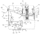
図3に示すように、ディスク記録再生装置21はディスクカートリッジ1を保持するとともにディスクカートリッジ1を装置内方に対して挿脱するための挿脱位置とディスクカートリッジ1に対する記録再生を行うためのカートリッジ装着位置とにディスクカートリッジ1を移動するカートリッジホルダ22と、このカートリッジホルダ22を移動可能に支持するベースシャーシ23と光磁気ディスク5に対して情報の記録再生を行うための光ピックアップ部24と光磁気ディスク5に対して情報の記録を行うための磁気ヘッド部25と光磁気ディスク5を回転駆動するためのディスク回転駆動機構26とを備えている。
【0022】
又、ディスク記録再生装置21は、図3〜図9に示すように、磁気ヘッド部25を光磁気ディスク5に対して昇降動作させるヘッド昇降機構27とディスク記録再生装置21の外方へディスクカートリッジ1の取出しの可否を切換えるための取出し操作切換え部材28とを備えている。
【0023】
カートリッジホルダ22は、図3に示すように、挿脱されるディスクカートリッジ1の主面に対向する位置に形成された天板29と、この天板29に磁気ヘッド挿入用開口部30を備えている。又、カートリッジホルダ22には、シャッタ部材10を開閉操作し、係合穴13に係合する移動規制部材31が設けられている。このカートリッジホルダ22は、ベースシャーシ23に回動支軸を介して回動可能に支持されている。
【0024】
ベースシャーシ23はディスクカートリッジ1の主面の外形より僅かに大きな矩形に形成されており、主面の略中央部に、光磁気ディスク5を回転駆動するディスク回転駆動機構26が配設されている。
【0025】
光ピックアップ部24は、図示しないが、レーザー光を出射する光源と光磁気ディスク5の記録領域にレーザー光を合焦させる対物レンズと、この対物レンズを二軸方向に駆動変位させる二軸アクチュエータと、記録領域からの戻り光を受光する受光部とを有している。この光ピックアップ部24は、ベースシャーシ23上に図示しない送り機構を介して光磁気ディスク5の径方向に移動可能に配設されている。
【0026】
磁気ヘッド部25は、図3に示すように、光ピックアップ部24に対向する位置に配置されている。磁気ヘッド部25は、図3〜図9に示すように、光磁気ディスク5に対して情報を記録する磁気ヘッド32とこの磁気ヘッド32を先端部に支持する支持アーム33と支持アーム33を変位可能に保持する支持板34と、磁気ヘッド32を上昇時保持する磁気ヘッド保持板35とを有している。磁気ヘッド保持板35は、支持アーム33に結合されており、支持アーム33と同様に支持板34に対して可動である。支持板34の基端部は、磁気ヘッド部25と光ピックアップ部24を連結する連結部材36に結合されており、図5中矢印a1
及びa2 方向に揺動可能である。
【0027】
そして、これらの光ピックアップ部24及び磁気ヘッド部25は、連結部材36を介してベースシャーシ23上を光磁気ディスク5の径方向に一体的に移動する。
【0028】
ディスク回転駆動機構26は、図3に示すように、ディスクカートリッジ1の光磁気ディスク5が載置されるディスクテーブル37とこのディスクテーブルを回転駆動するスピンドルモータ38とを有している。スピンドルモータ38は、ベースシャーシ23の主面に突出されて配設されている。
【0029】
ヘッド昇降機構27は、図3及び図4に示すように、カートリッジホルダ22の天板29上面にディスクカートリッジ1内の光磁気ディスク5に対して磁気ヘッド部25の磁気ヘッド32を近接離間する方向に昇降動作させるために図5中矢印a1
方向及びa2 方向に回動される昇降操作板39と昇降操作板39を回動動作させるために図3及び図4中矢印b1 方向及びb2 方向に回動操作される回動操作レバー40とを有している。
【0030】
昇降操作板39は略平板状に形成されており、両側に、支持片41がそれぞれ一体に形成されており、これらの支持片41の先端部にカートリッジホルダ22に図4中矢印a1
方向及びa2 方向に回動可能に支持される回動支軸42がそれぞれ一体に突出形成されている。
【0031】
昇降操作板39には、図3に示すように、一端側の支持アーム33に対向する位置に、磁気ヘッド部25の支持アーム33に当接する当接部43が一体に形成されている。昇降操作板39には回動操作レバー40によって回動操作されるための作動片44と、移動規制部材31より延伸した昇降操作板付勢部45と当接する当接部46が一体に形成されている。
【0032】
回動操作レバー40は、カートリッジホルダ22上に図3中矢印b1
方向及びb2 方向に軸を中心に回動可能に支持され、昇降操作板39を回動操作するための操作部47と昇降制御機構48に連結される連結部とを有している。操作部47は、図3に示すように、回動中心から昇降操作板39の近傍位置まで延設されており、先端部に回動方向と略直角方向に突出された操作片49と昇降操作板39との係合部50が一体に形成されている。この操作片49は昇降操作板39の作動片44に当接する。連結部51は、図5に示すように、カートリッジホルダ22の天板29の主面に直交して形成されており、先端部が昇降制御機構48に連結されている。
【0033】
昇降制御機構48は、図3に示すように、ベースシャーシ23の下面側に配設され、磁気ヘッド32の昇降を制御する昇降制御レバー52とディスクカートリッジ1の取出し可否を切換える取出し操作切換え部材28と昇降制御レバー52の位置を検出する検出手段53と昇降制御レバー52を移動操作する駆動手段59を有している。
【0034】
昇降制御レバー52は、主面上にガイドスリット53,53がそれぞれ形成されており、これらのガイドスリット53,53内にベースシャーシ23に立設されたガイド軸54,54がそれぞれ移動可能に挿通されている。ベースシャーシ23には昇降制御レバー52の移動を検出する検出部55を有している。又、昇降制御レバー52には、回動操作レバー40を駆動する駆動部56と、検出部55と当接する階段状のカム部57と、取出し操作切換え部材28を駆動する駆動軸58と、駆動手段59と係合するラック部60が設けられている。
【0035】
取出し操作切換え部材28はベースシャーシ23に立設された回動軸61を中心に図3及び図4中d1
方向及びd2 方向に回動可能で中央付近に設けられたガイドカム62が昇降制御レバー52の駆動軸58と係合して動作される。
【0036】
回動操作レバー駆動部56は、角穴形状でベースシャーシ23の外方に臨み、回動操作レバー40の連結部51の先端が挿入されている。ラック部60は、駆動手段59に設けられたギア63と噛合い、昇降制御レバー52は図中矢印c1方向及びc2 方向に駆動される。
【0037】
昇降制御レバー駆動手段59は、駆動源であるモータ64と減速機構であるギア63を有しており、ギアは昇降制御レバー52のラック部60と噛合っている。
【0038】
ベースシャーシ23のカートリッジ挿脱側外方にはカートリッジ取出し操作部65が設けられ、図3及び図4のe1
方向及びe2 方向に移動可能である。取出し操作部65には取り出し切換えレバー28が侵入する開口部66が設けられている。
【0039】
以上のように構成された磁気ヘッド昇降制御装置について、磁気ヘッド部25の磁気ヘッド32が光磁気ディスク5に対して昇降される動作を図面を参照して説明する。
【0040】
先ず、昇降制御機構は、図5に示すように、初期状態で回動操作レバー40の操作片49が昇降操作板39の作動片44に当接されており、昇降操作板39が図5の矢印a2
方向に回動されている。そうすることにより、昇降操作板39の当接部43が磁気ヘッド部25の支持アーム33を介して磁気ヘッド32が光磁気ディスク5に対して離間した退避位置に移動されている。このとき、移動規制部材31の昇降操作板付勢部45と昇降操作板39の当接部46が当接し、昇降操作板39のa2
方向への回動が付勢されている。
【0041】
昇降制御レバー52は図4中c1 方向に片寄せされており、昇降制御レバー52上の駆動軸58に連動して、取出し操作切換え部材28はd1
方向に片寄せされ、取出し操作部65は開口部66に取出し操作切換え部材28が挿入されておらず、カートリッジ取出し操作が可能な状態にある。この状態でカートリッジホルダ22をa2
方向に回動させれば、磁気ヘッド32が光磁気ディスク5から離間した状態でのカートリッジ取出し操作が可能である。
【0042】
次に、図7〜図9を参照して説明する。
【0043】
磁気ヘッド昇降制御機構は、ディスク記録再生装置21の操作によりモータ64が駆動され、ギア63を通して駆動力が伝達され昇降制御レバー52が図5中矢印c2
方向に駆動される。ベースシャーシ23上の検出部55と昇降制御レバー52のカム部57が当接し、その検出信号によりモータ64の回転が停止し、昇降制御レバー52も停止する。昇降制御レバー52の移動中には、回動操作レバー駆動部56と連結された回動操作レバー連結部51が駆動され、回動操作レバー40は図7中矢印b2
方向に回動される。
【0044】
回動操作レバー40の操作部47先端に設けられた操作片49の傾斜に従って昇降操作板39の作動片44が駆動され、昇降操作板39は図8中矢印a1
方向に回動する。昇降操作板39の当接部43が磁気ヘッド部25の支持アーム33を介して磁気ヘッド32が光磁気ディスク5と近接した記録位置に移動される。このため、磁気ヘッド部25は、磁気ヘッド32が光磁気ディスク5の記録領域に臨まされて、情報の記録が可能とされる。昇降操作板39の作動片44は回動操作レバー40の係合部50に下側に進入し、昇降操作板39のa2
方向の回動を規制している。
【0045】
取出し操作切換え部材28は、昇降制御レバー52の駆動軸58とガイドカム62の係合により図5中矢印d2
方向に回動され、取出し操作部65の開口部66に取出し操作切換え部材28が進入し。取出し操作が不可能となる。即ち、磁気ヘッド32が光磁気ディスク5に近接した記録状態にあるときはカートリッジの取出し操作を禁止している。
【0046】
昇降制御レバー52は図中c2 方向に長さL1 移動する間に、取出し操作切換え部材28は図中d2 方向に回動する。昇降制御レバー52の動作方向の長さL1 に比べ、取出し操作切換え部材28の同一方向の移動長さL2 は短くなるようにガイドカム62は設計されており、ディスク記録再生装置21の外方に取出し操作部65の動作を禁止する取出し操作切換え部材28が大きく突出することがない。
【0047】
又、取出し操作切換え部材28を昇降制御レバー52と別体で設けているため、回動操作レバー40の回動角が大きく取れ、操作片49の磁気ヘッド部25を近接位置から離間位置へ上昇させるカムの傾斜角度を小さくすることができる。
【0048】
上述したように、この磁気ヘッド昇降制御装置によれば、昇降制御レバー52の移動長さを取出し操作切換え部材28移動長さと異なって長く取ることができるためにヘッド昇降用のカムの傾斜を小さくすることで駆動負荷が低減でき、駆動モータの小型化或は減速機構の廃止により、ディスク記録再生装置を小型化することが可能になる。
【0049】
<実施の形態2>
次に、本発明の実施の形態2について図10〜図13を参照して説明する。
【0050】
本実施の形態では実施の形態1でベースシャーシ23に回動可能に設けられた取出し操作切換え部材が昇降制御レバー上に搭載された構成である。尚、ここでは実施の形態1と同一の機能を有する部材には同一符号を付して重複する説明を省略する。
【0051】
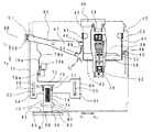
本実施の形態では、図10に示すように、昇降制御レバー71上に取出し操作切換え部材72が昇降制御レバー71に対して図中矢印c1
方向及びc2 方向に移動可能に配設されており、昇降制御レバー71の開口部73と取出し操作切換え部材72の開口部74内に設けられた圧縮バネ75により、取出し操作切換え部材の第1ストッパ部76は昇降制御レバー71の当接部77と当接し、図中矢印c2
方向に常に付勢されている。
【0052】
又、ベースシャーシ23には昇降制御レバーの位置検出を行う検出部78a,78bが設けられている。
【0053】
図10は本実施の形態における磁気ヘッド部25が光磁気ディスク5から離間した状態を示し、検出部78a,78bは昇降制御レバー71のカム部79とはどちらも当接していない状態である。
【0054】
図11は図10の状態から昇降制御レバー71がc2
方向に全移動長さL1 の略半分程度移動した状態である。図12に示すように、回動操作レバー40の操作片49と昇降操作板39の作動片44は、操作片49のカムの高い位置で当接しており、磁気ヘッド部25は、光磁気ディスク5から離間したままである。昇降制御レバー71上の取出し操作切換え部材72は、昇降制御レバー71と同じだけ移動し、先端部80がベースシャーシ23の切欠き部81及び取出し操作部の開口部66に進入している。
【0055】
又、第2ストッパ部82は、ベースシャーシ23の切欠き部81の側壁83に当接している。圧縮バネ75は、図10と同じ状態で昇降制御レバー71と取出し操作切換え部材72の位置関係は変わっていない。検出部78aは、カム部79aとの当接を検出して、駆動を停止することが可能である。この状態では、磁気ヘッド部25が光磁気ディスク5から離間位置にあってもディスクカートリッジ1の取出しは禁止されている。
【0056】
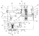
図13は図11から更にc2 方向に昇降制御レバー71が移動した状態を示している。回動操作レバー40はb2
方向に回動し、昇降操作板39の作動片44は、操作片49から離れ、磁気ヘッド部25は、光磁気ディスク5に近接した位置に下降する。昇降制御レバー71のカム部79bは、検出部78bに当接し、検出部78a,78b共にONになり、駆動手段が停止する。圧縮バネ75は、昇降制御レバー側がc2
方向に押され圧縮され、昇降制御レバー71と取出し操作切換え部材72との相対位置が変化する。実施の形態1と同様に昇降制御レバーの移動長さL1
に比べ、取出し操作切換え部材の同一方向の移動長さL3 を短くすることが可能になる。
【0057】
従って、磁気ヘッド部25が光磁気ディスク5から離間した状態で、ディスク記録再生装置としてディスクカートリッジ1の取出し可否を選択することが可能になる。
【0058】
更に、実施の形態1においては、磁気ヘッド部25の上昇位置と下降位置との間に停止位置を設けず操作片のカムの傾斜を連続にしたが、本実施の形態のように中間に、例えば、光磁気ディスクから僅かに離間した位置に昇降制御レバーが停止できるように検出部を設けることが可能である。こうすることにより磁気ヘッド部が全て上昇した位置ではなく、下降すればすぐに再生動作が可能になるので、操作性の良好なディスク記録再生装置を実現することが可能になる。
【0059】
【発明の効果】
以上の説明で明らかなように、本発明に係る磁気ヘッド昇降制御装置によれば、磁気ヘッドの昇降制御レバーの移動長さと、ディスクカートリッジ取出し操作切換え部材の移動長さを異ならすことができるため、駆動力の低減により、ディスク記録再生装置の小型化、省電力化、部品点数削減による製造コストの低減が可能になる。
【0060】
又、この磁気ヘッド昇降制御装置によれば、ディスクカートリッジ取出しの可否を磁気ヘッド部の上昇位置、下降位置の2箇所の他に増やすことができるので、ディスク記録再生装置の操作性の向上や高機能化を図ることができる。
【図面の簡単な説明】
【図1】本発明に係るディスク記録再生装置に用いられるディスクカートリッジを示す斜視図である。
【図2】ディスクカートリッジの下面側を示す斜視図である。
【図3】本発明に係るディスク記録再生装置を示す平面図である。
【図4】本発明に係る磁気ヘッド昇降制御装置の実施の形態1で磁気ヘッド昇降制御機構が磁気ヘッドを光磁気ディスクから離間した上昇位置を示す平面図である。
【図5】図4の一方の側を示す側面図である。
【図6】図4の他方の側を示す側面図である。
【図7】本発明に係る磁気ヘッド昇降制御装置の実施の形態1で磁気ヘッド昇降制御機構が磁気ヘッドを光磁気ディスクに近接した下降位置を示す平面図である。
【図8】図7の一方の側を示す側面図である。
【図9】図7の他方の側を示す側面図である。
【図10】本発明に係る磁気ヘッド昇降制御装置の実施の形態2で磁気ヘッド昇降制御機構が磁気ヘッドを光磁気ディスクから離間した上昇位置を示す平面図である。
【図11】本発明に係る磁気ヘッド昇降制御装置の実施の形態2で磁気ヘッド昇降制御機構が昇降制御レバーを中間位置に移動した状態示す平面図である。
【図12】図11の一方の側を示す側面図である。
【図13】本発明に係る磁気ヘッド昇降制御装置の実施の形態2で磁気ヘッド昇降制御機構が磁気ヘッドを光磁気ディスクに近接した下降位置を示す平面図である。
【符号の説明】
1 ディスクカートリッジ
2 上ハーフ
3 下ハーフ
4 カートリッジ本体
5 光磁気ディスク
6 ディスクハブ
7 中央開口部
8 記録用開口部
9 記録再生用開口部
10 シャッタ部材
11 シャッタロック部材
12 シャッタ開放部材侵入溝
13 係合穴
21 ディスク記録再生装置
22 カートリッジホルダ
23 ベースシャーシ
24 光ピックアップ部
25 磁気ヘッド部
26 ディスク回転駆動機構
27 ヘッド昇降機構
28 取出し操作切換え部材
29 天板
30 磁気ヘッド挿入用開口部
31 移動規制部材
32 磁気ヘッド
33 支持アーム
34 支持板
35 磁気ヘッド保持板
36 連結部材
37 ディスクテーブル
38 スピンドルモータ
39 昇降操作板
40 回動操作レバー
41 昇降操作板支持片
42 昇降操作板回動支軸
43 昇降操作板の支持アーム当接部
44 昇降操作板作動片
45 移動規制部材31の昇降操作板付勢部
46 (昇降操作板付勢部との) 当接部
47 (回動操作レバーの昇降操作板) 操作部
48 昇降制御機構
49 (回動操作レバーの昇降操作板) 操作片
50 回動操作レバーの係合部
51 (回動操作レバーの昇降制御機構との)
連結部
52 昇降制御レバー
53,53 ガイドスリット
54,54 (昇降制御レバー) ガイド軸
55 (昇降制御レバー) 検出部
56 回動操作レバー駆動部
57 (検出部と当接する) カム部
58 (取出し操作切換え部材) 駆動軸
59 昇降制御レバー駆動手段
60 ラック部
61 (取出し操作切換え部材) 回転軸
62 ガイドカム
63 ギア
64 駆動モータ
65 カートリッジ取出し操作部
66 取出し操作部の開口部
71 昇降制御レバー
72 取出し操作切換え部材
73 昇降制御レバー開口部
74 取出し操作切換え部材開口部
75 圧縮バネ
76 取出し操作切換え部材第1ストッパ部
77 昇降制御レバー当接部
78a,78b 検出部
79a,79b カム部
80 取出し操作切換え部材先端部
81 ベースシャーシ切欠き部
82 取出し操作切換え部材第2ストッパ部
83 切欠き部側壁[0001]
TECHNICAL FIELD OF THE INVENTION
The present invention relates to a magnetic head used for recording and / or reproducing an information signal on a disk-shaped recording medium such as a magneto-optical disk capable of recording an information signal. The present invention relates to a lift control device for a magnetic head that moves up and down between a magnetic recording medium and an ascending position separated from the recording medium.
[0002]
[Prior art]
2. Description of the Related Art Conventionally, there has been used a disk recording / reproducing apparatus using a magneto-optical disk capable of recording an information signal as a recording medium by the action of a light beam emitted from an optical pickup device and an external magnetic field applied from a magnetic head.
[0003]
When recording an information signal on a magneto-optical disk, this type of disk recording / reproducing apparatus brings a magnetic head close to a main surface of a magneto-optical disk in which a signal recording area is provided. When reproducing an information signal recorded on a magneto-optical disk, the application of an external magnetic field from the magnetic head is unnecessary, so that the magnetic head is moved to a position separated from the main surface of the magneto-optical disk. You.
[0004]
By thus separating the magnetic head from the magneto-optical disk when it is not necessary to use the magnetic head, it is possible to prevent the magnetic head and the magneto-optical disk from being worn due to the relative sliding contact between the magnetic head and the magneto-optical disk. Thus, the durability of the magnetic head and the magneto-optical disk is improved.
[0005]
In a disk recording / reproducing apparatus using a magneto-optical disk capable of recording an information signal as a recording medium, the apparatus is rotatably supported by an apparatus main body in which an optical pickup device constituting a disk rotation drive mechanism and recording / reproducing means is arranged. A disk cartridge is loaded into a recording / reproducing position on the apparatus body side by using a holder. This disk recording / reproducing apparatus is configured such that a magnetic head is attached to the tip of a head support arm extended on a holder, and the head support arm is rotated in conjunction with the rotation of the holder.
[0006]
In a disk recording / reproducing apparatus in which a head support arm supporting a magnetic head is extended on a holder rotatably supported by the apparatus main body as described above, when recording an information signal, The magnetic head is brought into sliding contact with the magneto-optical disk loaded at the recording / reproducing position where the magnetic head has entered the holder through the provided magnetic head insertion opening. In this disk recording / reproducing apparatus, if the disk cartridge is inserted and removed while the magnetic head remains in the holder, the disk cartridge collides with the magnetic head and damages the magnetic head.
[0007]
Therefore, in order to reliably prevent the disk cartridge from colliding with the magnetic head when the disk cartridge is inserted into or removed from the holder, this type of disk recording / reproducing apparatus uses the magnetic head to transmit an information signal recorded on the magneto-optical disk. The playback position is further moved from the playback position to the ascending position that has escaped outside the holder.
[0008]
By the way, a disc recording / reproducing apparatus using a magneto-optical disc capable of recording an information signal as a recording medium is capable of ejecting a magneto-optical disc loaded at a recording / reproducing position in a recording mode for recording an information signal on the magneto-optical disc. In addition, the position of the magnetic head is controlled to rise and fall according to a reproduction mode for reproducing an information signal recorded on a magneto-optical disk. The lifting control of the magnetic head is configured to be performed by moving a lifting control lever for lifting and lowering a lifting operation member for lifting and lowering the magnetic head by a drive motor.
[0009]
The elevating operation member and the elevating control lever are connected by a connecting member.
[0010]
In order to control the elevating position of the magnetic head according to each operation mode, the position of the elevating operation lever or the connecting member is detected to detect the position of the magnetic head, and the drive motor is operated in accordance with the detected position of the magnetic head. Is driven and controlled.
[0011]
[Problems to be solved by the invention]
A conventional disk recording / reproducing apparatus has two positions, a recording mode position, a reproducing mode position, and an eject position, depending on the position of the magnetic head. The magnetic head is often moved up and down by a cam provided on a connecting member. The magnetic head is raised by driving the lifting / lowering operation member.However, in order to raise the magnetic head biased to the lowering position of the reproduction mode by a biasing member or the like in order to lift the magnetic head against the biasing force, a disk is required. In order not to increase the size of the recording / reproducing apparatus, the angle of the cam is sharpened in order to perform the up / down operation with a limited amount of movement of the up / down operation lever, so that a driving source (motor) having a large driving force or a driving force Since a speed reduction mechanism is required, it is difficult to further reduce the size.
[0012]
SUMMARY OF THE INVENTION An object of the present invention is to provide a magnetic head lifting / lowering control device capable of further reducing the size of a disk recording / reproducing device.
[0013]
It is another object of the present invention to provide a magnetic head elevating device capable of providing a plurality of magnetic head positions without increasing the size of the disk recording / reproducing apparatus, and increasing the number of operation modes depending on the position of an elevating operation lever. It is to provide a control device.
[0014]
[Means for Solving the Problems]
In order to achieve the above object, the present invention provides a magnetic head which is moved up and down between a descending position close to a disk-shaped recording medium and an ascending position separated from the disk-shaped recording medium, and elevating the magnetic head. A lifting / lowering control lever for controlling, a detecting means for detecting a movement position of the lifting / lowering control lever, a removal operation unit for performing a removal operation of a cartridge containing the disk-shaped recording medium out of the apparatus, and a lifting / lowering control lever. A pick-up operation switching member for switching whether or not the pick-up operation unit is allowed to operate, wherein the pick-up operation switching member is driven by movement of the elevation control lever to control the pick-up operation unit.
[0015]
BEST MODE FOR CARRYING OUT THE INVENTION
<
Hereinafter, a disk recording / reproducing apparatus and a magnetic head lifting / lowering control apparatus according to the present invention will be described with reference to the drawings.
[0016]
First, a disk cartridge used in the disk recording / reproducing apparatus according to the present embodiment will be described. As shown in FIGS. 1 and 2, a pair of upper and
[0017]
In addition, a recording opening 8 and a recording / reproducing opening 9 for exposing a part of a signal recording area formed on the main surface of the magneto-
[0018]
A
[0019]
At the center of the connecting
[0020]
The
[0021]
As shown in FIG. 3, a disk recording / reproducing
[0022]
Also, as shown in FIGS. 3 to 9, the disk recording / reproducing
[0023]
As shown in FIG. 3, the
[0024]
The
[0025]
Although not shown, the
[0026]
The
And a2 direction.
[0027]
Then, the
[0028]
As shown in FIG. 3, the disk
[0029]
As shown in FIGS. 3 and 4, the head elevating mechanism 27 moves the
The lifting
[0030]
The elevating
The
[0031]
As shown in FIG. 3, a
[0032]
The
The
[0033]
As shown in FIG. 3, the lifting
[0034]
The elevating
[0035]
The take-out
A
[0036]
The turning operation
[0037]
The elevating control lever driving means 59 has a
[0038]
A cartridge take-out
And e2 direction. The take-out
[0039]
The operation of moving the
[0040]
First, as shown in FIG. 5, in the lifting control mechanism, the
Direction. As a result, the
The rotation in the direction is biased.
[0041]
The elevating
The
If the
[0042]
Next, a description will be given with reference to FIGS.
[0043]
The magnetic head lifting / lowering control mechanism is configured such that the
Driven in the direction. The
Pivoted in the direction.
[0044]
The
Rotate in the direction. The
Directional rotation is regulated.
[0045]
The take-out
The take-out
[0046]
While the elevating
[0047]
Further, since the take-out
[0048]
As described above, according to this magnetic head lifting / lowering control device, since the moving length of the lifting / lowering
[0049]
<
Next, a second embodiment of the present invention will be described with reference to FIGS.
[0050]
In the present embodiment, a take-out operation switching member rotatably provided on the
[0051]
In the present embodiment, as shown in FIG. 10, a take-out
The first stopper of the take-out operation switching member is provided by a
Always biased in the direction.
[0052]
The
[0053]
FIG. 10 shows a state in which the
[0054]
FIG. 11 shows that the elevating
It is in a state where it has moved about half of the total movement length L1 in the direction. As shown in FIG. 12, the
[0055]
The
[0056]
FIG. 13 shows a state in which the elevating
The
The relative position between the
As compared with the above, the moving length L3 of the takeout operation switching member in the same direction can be shortened.
[0057]
Therefore, it is possible to select whether or not to take out the
[0058]
Further, in the first embodiment, the cam of the operation piece is continuously inclined without providing a stop position between the raised position and the lowered position of the
[0059]
【The invention's effect】
As apparent from the above description, according to the magnetic head lifting / lowering control device of the present invention, the moving length of the lifting / lowering control lever of the magnetic head can be made different from the moving length of the disk cartridge ejection operation switching member. By reducing the driving force, it is possible to reduce the size and power consumption of the disk recording / reproducing apparatus and reduce the manufacturing cost by reducing the number of components.
[0060]
Further, according to this magnetic head lifting / lowering control device, the possibility of taking out the disk cartridge can be increased in addition to the two positions of the magnetic head portion, ie, the raised position and the lowered position. Functionalization can be achieved.
[Brief description of the drawings]
FIG. 1 is a perspective view showing a disk cartridge used in a disk recording / reproducing apparatus according to the present invention.
FIG. 2 is a perspective view showing a lower surface side of the disk cartridge.
FIG. 3 is a plan view showing a disk recording / reproducing apparatus according to the present invention.
FIG. 4 is a plan view showing an ascending position where the magnetic head elevating control mechanism separates the magnetic head from the magneto-optical disk in the first embodiment of the magnetic head elevating control device according to the present invention;
FIG. 5 is a side view showing one side of FIG. 4;
FIG. 6 is a side view showing the other side of FIG.
FIG. 7 is a plan view showing a magnetic head lifting / lowering control device according to the first embodiment of the present invention, in which the magnetic head lifting / lowering control mechanism lowers the magnetic head close to the magneto-optical disk;
FIG. 8 is a side view showing one side of FIG. 7;
FIG. 9 is a side view showing the other side of FIG. 7;
FIG. 10 is a plan view showing an ascending position where the magnetic head elevating control mechanism separates the magnetic head from the magneto-optical disk in the second embodiment of the magnetic head elevating control device according to the present invention.
FIG. 11 is a plan view showing a state in which a magnetic head lifting / lowering control mechanism moves a lifting / lowering control lever to an intermediate position in a second embodiment of the magnetic head lifting / lowering control device according to the present invention;
FIG. 12 is a side view showing one side of FIG. 11;
FIG. 13 is a plan view showing a magnetic head lifting / lowering control device according to a second embodiment of the present invention, in which the magnetic head lifting / lowering control mechanism lowers the magnetic head close to the magneto-optical disk;
[Explanation of symbols]
1 disk cartridge
2 Upper half
3 Lower half
4 Cartridge body
5 Magneto-optical disk
6 disk hub
7 Central opening
8 Recording opening
9 Recording / playback opening
10 Shutter member
11 Shutter lock member
12 Shutter opening member entry groove
13 Engagement hole
21 Disc recording and playback device
22 Cartridge holder
23 Base chassis
24 Optical pickup unit
25 Magnetic head
26 Disk rotation drive mechanism
27 Head lifting mechanism
28 Extraction operation switching member
29 Top plate
30 Magnetic head insertion opening
31 Movement restriction member
32 magnetic head
33 Support arm
34 Support plate
35 Magnetic head holding plate
36 Connecting member
37 disk table
38 Spindle motor
39 Lifting operation plate
40 Rotating operation lever
41 Lifting operation plate support piece
42 Elevating operation plate rotation support shaft
43 Support arm contact part of lifting operation plate
44 Lifting operation plate operating piece
45 Elevating operation plate urging part of
46 Abutment part (with lifting part of urging operation plate)
47 (Elevating operation plate of rotation operation lever) Operation part
48 Elevation control mechanism
49 (Elevating operation plate of rotation operation lever) Operation piece
50 Engagement part of rotation operation lever
51 (with the lift control mechanism of the rotation operation lever)
Connection
52 Elevation control lever
53, 53 Guide slit
54, 54 (elevation control lever) Guide shaft
55 (elevation control lever) detector
56 Rotating operation lever drive
57 (Abuts on the detection unit) Cam unit
58 (Unloading operation switching member) Drive shaft
59 Lift control lever drive means
60 rack part
61 (Unloading operation switching member) Rotary shaft
62 Guide cam
63 gear
64 drive motor
65 Cartridge removal operation section
66 Opening of take-out operation section
71 Elevation control lever
72 Extraction operation switching member
73 Lifting control lever opening
74 Extraction operation switching member opening
75 Compression spring
76 Extraction operation switching member first stopper
77 Lift control lever contact part
78a, 78b detector
79a, 79b Cam section
80 Extraction operation switching member tip
81 Base chassis notch
82 Removal Operation Switching Member Second Stopper
83 Notch side wall
Claims (5)
Priority Applications (2)
| Application Number | Priority Date | Filing Date | Title |
|---|---|---|---|
| JP2002267673A JP2004103194A (en) | 2002-09-13 | 2002-09-13 | Control device for magnetic head rising/falling |
| US10/654,045 US7106663B2 (en) | 2002-09-13 | 2003-09-04 | Disk recording/reproducing apparatus provided with magnet head ascending/descending mechanism |
Applications Claiming Priority (1)
| Application Number | Priority Date | Filing Date | Title |
|---|---|---|---|
| JP2002267673A JP2004103194A (en) | 2002-09-13 | 2002-09-13 | Control device for magnetic head rising/falling |
Publications (2)
| Publication Number | Publication Date |
|---|---|
| JP2004103194A true JP2004103194A (en) | 2004-04-02 |
| JP2004103194A5 JP2004103194A5 (en) | 2005-11-04 |
Family
ID=31986714
Family Applications (1)
| Application Number | Title | Priority Date | Filing Date |
|---|---|---|---|
| JP2002267673A Pending JP2004103194A (en) | 2002-09-13 | 2002-09-13 | Control device for magnetic head rising/falling |
Country Status (2)
| Country | Link |
|---|---|
| US (1) | US7106663B2 (en) |
| JP (1) | JP2004103194A (en) |
Families Citing this family (4)
| Publication number | Priority date | Publication date | Assignee | Title |
|---|---|---|---|---|
| JP2005209267A (en) * | 2004-01-21 | 2005-08-04 | Canon Inc | Optical disk device and optical pickup |
| US7680013B2 (en) * | 2005-11-29 | 2010-03-16 | Canon Kabushiki Kaisha | Optical information recording and reproducing apparatus |
| US7943527B2 (en) * | 2008-05-30 | 2011-05-17 | The Board Of Trustees Of The University Of Illinois | Surface preparation for thin film growth by enhanced nucleation |
| CN106960676B (en) * | 2017-03-30 | 2019-02-22 | 广东工业大学 | A kind of optical pickup mobile device |
Family Cites Families (5)
| Publication number | Priority date | Publication date | Assignee | Title |
|---|---|---|---|---|
| WO1998002882A1 (en) * | 1996-07-11 | 1998-01-22 | Sony Corporation | Magnetic head lifting device of magneto-optical recorder and/or reproducer |
| CN1154993C (en) * | 1998-10-01 | 2004-06-23 | 索尼株式会社 | Recording and/or reproducing device using disk cartridge |
| US6411596B1 (en) * | 1999-03-16 | 2002-06-25 | Canon Kabushiki Kaisha | Magneto-optical disk cartridge and magneto-optical disk apparatus |
| US20040233582A1 (en) * | 2002-01-10 | 2004-11-25 | Yutaka Murakami | Magnetic head device |
| JP2003208766A (en) | 2002-01-16 | 2003-07-25 | Canon Inc | Optical pickup feed unit |
-
2002
- 2002-09-13 JP JP2002267673A patent/JP2004103194A/en active Pending
-
2003
- 2003-09-04 US US10/654,045 patent/US7106663B2/en active Active
Also Published As
| Publication number | Publication date |
|---|---|
| US7106663B2 (en) | 2006-09-12 |
| US20040051990A1 (en) | 2004-03-18 |
Similar Documents
| Publication | Publication Date | Title |
|---|---|---|
| EP0518259A2 (en) | Apparatus for carrying out recording and/or reproducing signals for disk-shaped recording medium | |
| JP2974868B2 (en) | Disk drive device and disk device | |
| KR100354460B1 (en) | Disc cartridge | |
| JP4165418B2 (en) | Disk drive device, frame, disk drive device set, electronic equipment | |
| JP4281704B2 (en) | Disk drive device and electronic device | |
| KR100464197B1 (en) | Lifting device of the magnetic head of the magneto-optical recording and / or reproducing apparatus | |
| JP2004103194A (en) | Control device for magnetic head rising/falling | |
| US6345030B1 (en) | Disk apparatus | |
| JP4254620B2 (en) | Disk drive device | |
| JP2007188582A (en) | Disk drive and base unit | |
| US6973660B2 (en) | Disk driver | |
| JP2006127719A (en) | Disk drive unit | |
| US7017169B2 (en) | Disk cartridge and disk recording and reproducing apparatus | |
| JPH07334903A (en) | Disk player | |
| JP4229012B2 (en) | Disk drive device | |
| KR200339946Y1 (en) | Device for distinguishing disk size of disk player | |
| US20080282271A1 (en) | Recording Medium Drive Device | |
| JP4133232B2 (en) | Information recording medium reproducing apparatus | |
| JP3769931B2 (en) | Disc loading device | |
| JP3703675B2 (en) | Disk drive device | |
| JP3717677B2 (en) | Information recording medium driving device | |
| JPH0745025A (en) | Optical disk drive device | |
| JP2005346896A (en) | Disk drive device | |
| JP2005267806A (en) | Disk driving device | |
| JPH07141811A (en) | Recording and/or reproducing device |
Legal Events
| Date | Code | Title | Description |
|---|---|---|---|
| RD01 | Notification of change of attorney |
Free format text: JAPANESE INTERMEDIATE CODE: A7421 Effective date: 20050311 |
|
| A521 | Written amendment |
Free format text: JAPANESE INTERMEDIATE CODE: A523 Effective date: 20050913 |
|
| A621 | Written request for application examination |
Free format text: JAPANESE INTERMEDIATE CODE: A621 Effective date: 20050913 |
|
| A977 | Report on retrieval |
Free format text: JAPANESE INTERMEDIATE CODE: A971007 Effective date: 20070531 |
|
| A131 | Notification of reasons for refusal |
Free format text: JAPANESE INTERMEDIATE CODE: A131 Effective date: 20070605 |
|
| A521 | Written amendment |
Free format text: JAPANESE INTERMEDIATE CODE: A523 Effective date: 20070726 |
|
| A02 | Decision of refusal |
Free format text: JAPANESE INTERMEDIATE CODE: A02 Effective date: 20071113 |