EP1464918B1 - Procédé et appareil pour mesurer la position d'un aimant par rapport à une place de mesure - Google Patents
Procédé et appareil pour mesurer la position d'un aimant par rapport à une place de mesure Download PDFInfo
- Publication number
- EP1464918B1 EP1464918B1 EP04003793.9A EP04003793A EP1464918B1 EP 1464918 B1 EP1464918 B1 EP 1464918B1 EP 04003793 A EP04003793 A EP 04003793A EP 1464918 B1 EP1464918 B1 EP 1464918B1
- Authority
- EP
- European Patent Office
- Prior art keywords
- magnetic field
- magnet
- measuring
- measuring location
- measured
- Prior art date
- Legal status (The legal status is an assumption and is not a legal conclusion. Google has not performed a legal analysis and makes no representation as to the accuracy of the status listed.)
- Expired - Lifetime
Links
- 238000000034 method Methods 0.000 title claims description 13
- 238000005259 measurement Methods 0.000 claims description 16
- 238000011156 evaluation Methods 0.000 description 10
- 206010028980 Neoplasm Diseases 0.000 description 2
- 238000001514 detection method Methods 0.000 description 2
- 230000015572 biosynthetic process Effects 0.000 description 1
- 238000005516 engineering process Methods 0.000 description 1
- 238000003780 insertion Methods 0.000 description 1
- 230000037431 insertion Effects 0.000 description 1
- 230000002452 interceptive effect Effects 0.000 description 1
- 238000012804 iterative process Methods 0.000 description 1
- 230000007774 longterm Effects 0.000 description 1
- 238000013178 mathematical model Methods 0.000 description 1
- 230000003068 static effect Effects 0.000 description 1
- 230000001629 suppression Effects 0.000 description 1
Images
Classifications
-
- G—PHYSICS
- G01—MEASURING; TESTING
- G01B—MEASURING LENGTH, THICKNESS OR SIMILAR LINEAR DIMENSIONS; MEASURING ANGLES; MEASURING AREAS; MEASURING IRREGULARITIES OF SURFACES OR CONTOURS
- G01B7/00—Measuring arrangements characterised by the use of electric or magnetic techniques
- G01B7/003—Measuring arrangements characterised by the use of electric or magnetic techniques for measuring position, not involving coordinate determination
-
- G—PHYSICS
- G01—MEASURING; TESTING
- G01D—MEASURING NOT SPECIALLY ADAPTED FOR A SPECIFIC VARIABLE; ARRANGEMENTS FOR MEASURING TWO OR MORE VARIABLES NOT COVERED IN A SINGLE OTHER SUBCLASS; TARIFF METERING APPARATUS; MEASURING OR TESTING NOT OTHERWISE PROVIDED FOR
- G01D5/00—Mechanical means for transferring the output of a sensing member; Means for converting the output of a sensing member to another variable where the form or nature of the sensing member does not constrain the means for converting; Transducers not specially adapted for a specific variable
- G01D5/12—Mechanical means for transferring the output of a sensing member; Means for converting the output of a sensing member to another variable where the form or nature of the sensing member does not constrain the means for converting; Transducers not specially adapted for a specific variable using electric or magnetic means
- G01D5/14—Mechanical means for transferring the output of a sensing member; Means for converting the output of a sensing member to another variable where the form or nature of the sensing member does not constrain the means for converting; Transducers not specially adapted for a specific variable using electric or magnetic means influencing the magnitude of a current or voltage
Definitions
- the invention relates to a method and a device for measuring the position, which have a magnet and a measuring location, which is in the magnetic field of the magnet to each other, wherein the magnet or the measuring location occupies a predetermined stationary position in the measurement.
- US 6,304,082 B1 is a multi-axis magnetometer for measuring the magnetic field strength in three orthogonal axes (X, Y, Z) known.
- US 5,622,169 a device and a method for locating a medical tube in the body of a patient, wherein on the medical tube, a permanent magnet is arranged, which has a strong magnetic field.
- a sensor device with preferably two magnetic coils is brought into the vicinity of the body to be tested and detects the static magnetic field associated with the permanent magnet.
- the output signals of the two sensor coils are evaluated, and differential signals of the two sensor signals are formed.
- magnetic sensors can be designed in such a way that they consist of three mutually perpendicularly arranged magnetic coils in order to carry out a measurement at two locations in each of all spatial directions.
- the publication US 6 129 668 discloses a system and method for determining the location and orientation of a medical device for long-term use, wherein a magnet is connected to the medical device.
- a magnet is connected to the medical device.
- three or more sets of magnetic sensors are used in which the sensor elements are arranged in a known manner. Each sensor element detects the strength of the magnetic field generated by the magnet in the three-dimensional space and outputs a corresponding sensor signal.
- the magnetic field gradient can also be determined.
- An iterative process is used to determine the actual location and orientation of the magnet. Predicted magnetic field values are compared with actually measured values and thus a detection result is concluded. Further steps will refine this detection result. The further steps take place until a desired degree of deviations is reached.
- the publication US 5,762,064 discloses a medical magnetic positioning system and method for determining the position of a magnet within a body, wherein at least two spaced-apart magnetic sensors are disposed on the body proximate a desired position of the magnet.
- the three-dimensional magnetic field of the magnet is detected by means of the at least two magnetic sensors and it can be determined from the at least two magnetic sensors after a corresponding evaluation of the desired location of the magnet.
- the magnetic sensors are triaxially measuring sensors, and both the location and the spatial orientation of the magnet with respect to the position of the magnetic sensors is determined.
- US Pat. No. 6,385,482 B1 a device and a method for determining a position, wherein a signal emitter unit is preferably arranged within a body, for example in the vicinity of a part to be examined, such as a tumor.
- the signals emitted by the signal emitter unit can be detected outside the body by means of corresponding receiver devices, so that the desired position, for example of the tumor, can be detected in an exact manner.
- the present invention is based on the object, an initially mentioned method and an aforementioned device in such a way that the mutual spatial positioning of a magnetic field generating magnet and a lying in the magnetic field location uninfluenced by interference fields can be determined.
- this object is achieved by the features of claim 1 and in the device by the features of claim 2.
- the magnetic field strength and / or the gradient at the measurement location becomes three-dimensional, i. determined in three orthogonal axes. From a deviation of the three-dimensionally determined magnetic field strength and / or the gradient of a reference magnetic field strength and / or reference magnetic field gradients, in which or at which the magnet and the measuring location have predetermined positions, the position measurement value for the relative position of magnet and Measuring location are formed to each other.
- the gradient reflects the curvature and direction of the magnetic field at the measuring location.
- 3D sensors three-dimensionally measuring sensors
- the signals corresponding to the position contain information both about the spatial location (x, y, z) and information about the direction or orientation with respect to the three spatial axes (X, Y, Z).
- At least four magnetic field sensors are provided, each of which magnetic field sensor measures the magnetic field strength three-dimensionally, i. in the three orthogonal X, Y, Z axes.
- the difference quotient of the field strength of the magnetic field is formed from at least two sensor signals and from the deviation of this difference quotient of a reference difference quotient, in which the magnet and the measuring location assume predetermined positions, the position measurement value for the relative position of the magnet and the measuring location is determined relative to each other.
- the partial difference quotients associated with the respective orthogonal axes in the X, Y and Z directions result in the gradients of the spatially extended magnetic field at the respective measuring location.
- the magnet which generates the magnetic field can be designed as a permanent magnet or as an electromagnet.
- a modulated magnetic field can be generated, wherein the strength and direction of the modulation measured at the measuring location are evaluated to determine the relative position from magnet to measuring location.
- either the magnet or the measuring location is arranged at a predetermined known stationary position.
- rotational movements and translational movements and combinations of these types of movement and the respective actual position of the moving component, in particular the operating element with which the magnet or measuring location is firmly connected can be detected in three orthogonal coordinates.
- the gradient of the magnetic field or the magnetic field strengths at the measuring location in the three orthogonal X, Y and Z axes can be determined at four known or specific measuring points with three-dimensionally measuring magnetic field sensors.
- the magnetic field sensors can be arranged on a circumference around a center forming the measuring location.
- the magnetic field strengths present at at least two measuring points are preferably determined by magnetic field sensors and the deviation from the assigned reference magnetic field strengths of the magnetic field sensors Position measurement determined.
- the magnetic field intensities of two measuring point pairs are evaluated for the determination of the position measured value.
- the method and the device are preferably used in the contactless generation of actuating signals or control signals in operating elements, for example switches and the like.
- operating elements for example switches and the like.
- the control elements or operating elements for generating the control signals or control signals can be moved three-dimensionally fixed with the magnets at a fixed measuring location or fixed to the measuring location with fixed magnets.
- the position measuring signals generated by the evaluation device then form the actuating signals or control signals for the devices to be operated.
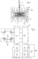
- a magnet 2 is attached to an operating element, for example in the form of a two-armed lever at the end of a lever arm.
- the magnet 2 which may be a permanent magnet or electromagnet, forms a magnetic field 3 with a specific field line direction. The direction the field strength coincides with the direction of the field lines in each point of the field.
- a measuring location 4 is arranged stationary.
- the measuring location 4 can be determined by four 3-dimensional magnetic field sensors 5, 6, 7, 8 (FIG. Fig. 2 ) are formed.
- the magnetic field sensors 5, 6, 7 and 8 are arranged on a circumference around the measuring location 4, which forms the center of the circumference.
- Each of the four magnetic field sensors measures the magnetic field strength along three orthogonal axes (X, Y, Z). Three-dimensional magnetic field sensors are known (eg US 6,304,082 B1 ).
- the operating element 1 may be, for example, a joy stick or another actuating element or actuating element.
- the movement of the magnet about a pivot point 13 takes place in all spatial directions, wherein the pivot point 13 can optionally be moved in the axial direction of the operating element 1 or in one or more specific directions in a plane perpendicular thereto.
- the movement of the magnet 2 and its respective position with respect to the fixed measuring location 4 is detected by two pairs of magnetic field sensors with a respective center at the measuring location 4, as will be explained below.
- the magnetic field sensors 5, 6, 7, 8 are connected to an evaluation device 9, wherein the components of the evaluation device 9 and the magnetic field sensors preferably on a chip as an integrated circuit, e.g. ASIC are provided.
- the evaluation device 9 which is preferably designed as an electronic evaluation device, includes an actual value generator 10 connected to the magnetic field sensors 5, 6, 7, 8. This forms from those obtained from the magnetic field sensors The actual values of the magnetic field strength in three orthogonal axes (X, Y, Z) for each of the magnetic field sensors 5, 6, 7 and 8. These actual values are compared with reference values of the magnetic field strengths in the respective X, Y and Z. Axes compared.
- the reference field strengths are stored in a reference memory 11.
- the reference field strengths can also be determined from a mathematical model.
- the reference field strengths are the field strengths at the locations of the magnetic field sensors 5, 6, 7 and 8, when the magnetic field 3 and thus the magnet 2 and the control element 1 is in a reference (zero) position. When the magnet 2 is moved out of this reference (zero) position upon actuation of the operating element 1, those of the
- Magnetic field sensors measured three-dimensional field strengths. These field strengths are, as already mentioned, detected by the actual value generator as actual field strengths and compared with the reference field strengths stored in the reference memory 11 in a comparator 12.
- the deviation of the actual values of the magnetic field strengths from the reference magnetic field strengths determined in the comparator 12 are a measure of the positional deviation of the magnet 2 from the reference (zero) position. This deviation also indicates the exact actual position of the magnet 2 and thus of the operating element 1.
- the magnetic field strengths in the three orthogonal axes (X, Y, Z) of a single magnetic field sensor or of a plurality of the four magnetic field sensors can be detected and evaluated.
- the field strength measurement signals of two magnetic field sensors can be evaluated to determine a gradient of the magnetic field 3.
- the difference quotient which is a measure for the curvature and direction of the magnetic field at the measuring location 4
- the measuring signals of at least two diametrically opposed to the measuring location 4 magnetic field sensors are used.
- the measurement signals of the two magnetic field sensors 5 and 8 or the two magnetic field sensors 6 and 7 are used.
- a reference gradient which is stored in a reference gradient memory 15.
- the reference gradient in the memory 15 corresponds to the reference gradient, which was determined at the measuring location 4 by means of the magnetic field sensors 5, 6, 7 and 8 at an initial position (reference or zero position) of the operating element 1 and the magnet 2.
- a comparator 16 the deviation of the actual value of the magnetic field gradient from the reference value of the magnetic field gradient is determined, wherein the deviation in the three orthogonal axes is a measure of the spatial position of the magnet 2 and thus of the operating element 1.
- the measured values change both for the field strengths, which are detected in the actual value 10 and for the gradient, which is detected in the gradient generator 14 in the three orthogonal X- , Y and Z axes.
- Positioning shown is measured at the magnetic field area designated 3 1 at the stationary measuring location 4.
- the magnetic field region designated 3 2 reaches the stationary measuring location 4.
- the directions of the magnetic field are schematically, ie only in the drawing plane, with arrows extending tangentially to the field lines.
- the magnet 2 is moved by the operating element 1.
- the magnet 2 it is also possible to arrange the magnet 2 in a stationary manner and to move the measuring location 4, in particular the chip on which the three-dimensionally measuring magnetic field sensors 5, 6, 7 and 8 are located, through the operating element 1 in the magnetic field 3.
- the signals of the comparators 12 and / or 16 which are proportional to the respective relative positioning of measuring location 4 and magnet 2 or operating element 1, are forwarded to a control device 17, by means of which in dependence on these position signals, the control of a device not shown he follows.
- the invention described is suitable for controlling physical quantities in all areas of technology.
- a modulated magnetic field 3 can be generated. From the measured at the measuring point strength and direction of the modulation or the change in the modulation of the measured actual values of the magnetic field strengths in the three orthogonal axes relative to the corresponding reference modulation also one of the position of the magnetic field or the magnet 1 relative to the measurement site 4 corresponding position signal is formed become.
- the rotor position in the electric motor can be determined continuously with the aid of the three-dimensional measurement of the magnetic field strength. Further, the position of electromagnet moving parts in relays, openers and the like can be determined.
Landscapes
- Physics & Mathematics (AREA)
- General Physics & Mathematics (AREA)
- Measurement Of Length, Angles, Or The Like Using Electric Or Magnetic Means (AREA)
Claims (3)
- Procédé de mesure de la position, que présente un aimant par rapport à un lieu de mesure agencé dans le champ magnétique de l'aimant, procédé d'après lequel on mesure au niveau du lieu de mesure, les intensités de champ magnétique dans trois axes orthogonaux (x, y, z), au moyen de capteurs de champ magnétique (5, 6, 7, 8) mesurant dans trois dimensions, et l'aimant ou le lieu de mesure présente une position prédéterminée lors de la mesure,
d'après lequel
au niveau du lieu de mesure, on procède respectivement en au moins deux paires de points de mesure, qui sont situées sur une circonférence circulaire, à la mesure des intensités de champ magnétique dans les trois axes orthogonaux, et on traite et exploite les intensités de champ magnétique mesurées pour la détermination de la position de l'aimant par rapport à une position de référence de l'aimant,
le lieu de mesure se situe au centre de la circonférence circulaire, et d'après lequel
à partir des valeurs de mesure des intensités de champ magnétique de respectivement deux capteurs de champ magnétique, on forme un quotient de différences des intensités de champ magnétique, et à partir d'un écart du quotient de différences par rapport à un quotient de différences de référence mémorisé, on détermine une valeur de mesure de position pour la position relative de l'aimant et du lieu de mesure. - Dispositif de mesure de la position, que présente un aimant (2) par rapport à un lieu de mesure (4) prévu dans le champ magnétique de l'aimant, l'aimant ou le lieu de mesure ayant une position prédéterminée lors de la mesure, le dispositif
comprenant au moins deux paires de capteurs de champ magnétique (5, 6, 7, 8) agencées au niveau du lieu de mesure et mesurant l'intensité de champ magnétique dans trois axes orthogonaux (x, y, z), et
comprenant une unité d'exploitation et de traitement de données (9) raccordée aux capteurs de champ magnétique des paires de capteurs de champ magnétique, pour déterminer la position relative entre l'aimant et le lieu de mesure à partir des signaux de mesure des capteurs de champ magnétique,
dispositif
dans lequel lesdites au moins deux paires de capteurs de champ magnétique (5, 6, 7, 8) sont agencées sur une circonférence circulaire, dont le centre est le lieu de mesure (4) et forme le centre commun desdites au moins deux paires de capteurs de champ magnétique, et l'unité d'exploitation et de traitement de données (9) comprend un élément de formation de différences (14) pour former un quotient de différences à partir d'au moins deux intensités de champ magnétique mesurées des capteurs de champ magnétique,
et dans lequel l'unité d'exploitation et de traitement de données (9) est conçue pour former une valeur de mesure de position pour la position relative de l'aimant et du lieu de mesure par rapport à une position de référence de l'aimant, à partir d'un écart du quotient de différences par rapport à un quotient de différences de référence mémorisé. - Utilisation d'un procédé selon la revendication 1 et d'un dispositif selon la revendication 2 pour commander une grandeur physique en fonction de la valeur de mesure de position, qui est formée à l'aide du procédé et /ou du dispositif, et qui indique la position relative de l'aimant et du lieu de mesure.
Applications Claiming Priority (2)
| Application Number | Priority Date | Filing Date | Title |
|---|---|---|---|
| DE10314838 | 2003-04-01 | ||
| DE2003114838 DE10314838A1 (de) | 2003-04-01 | 2003-04-01 | Verfahren und Vorrichtung zur Messung der Position, welche ein Magnet und ein Messort zueinander haben |
Publications (3)
| Publication Number | Publication Date |
|---|---|
| EP1464918A2 EP1464918A2 (fr) | 2004-10-06 |
| EP1464918A3 EP1464918A3 (fr) | 2008-12-10 |
| EP1464918B1 true EP1464918B1 (fr) | 2016-11-16 |
Family
ID=32842207
Family Applications (1)
| Application Number | Title | Priority Date | Filing Date |
|---|---|---|---|
| EP04003793.9A Expired - Lifetime EP1464918B1 (fr) | 2003-04-01 | 2004-02-19 | Procédé et appareil pour mesurer la position d'un aimant par rapport à une place de mesure |
Country Status (2)
| Country | Link |
|---|---|
| EP (1) | EP1464918B1 (fr) |
| DE (1) | DE10314838A1 (fr) |
Families Citing this family (16)
| Publication number | Priority date | Publication date | Assignee | Title |
|---|---|---|---|---|
| DE102005009381A1 (de) | 2005-03-01 | 2006-09-14 | Robert Seuffer Gmbh & Co. Kg | Verfahren und Vorrichtung zur Bestimmung der jeweiligen Position wenigstens eines Messortes in einem Permanentmagnetfeld |
| DE102007001745A1 (de) | 2007-01-11 | 2008-07-17 | Robert Seuffer Gmbh & Co. Kg | Joystick mit Haptik |
| DE102007028739B4 (de) | 2007-06-21 | 2012-02-23 | Seuffer Gmbh & Co.Kg | Waschmaschine |
| US8122783B2 (en) | 2008-02-22 | 2012-02-28 | Sauer-Danfoss Inc. | Joystick and method of manufacturing the same |
| EP2369291B1 (fr) * | 2010-03-10 | 2015-09-23 | PolyResearch AG | Capteur pour la mesure de la hauteur |
| DE102010003292A1 (de) * | 2010-03-25 | 2011-09-29 | Fraunhofer-Gesellschaft zur Förderung der angewandten Forschung e.V. | Sensoranordnung und Verfahren zum Ermitteln einer Magnetisierungseinrichtung eines Gebermagneten |
| DE102010034482A1 (de) * | 2010-08-10 | 2012-04-19 | Carl Zeiss Industrielle Messtechnik Gmbh | Sensoranordnung und Verfahren zum Bestimmen einer räumlichen Position eines ersten Teils relativ zu einem zweiten Teil |
| DE202011002747U1 (de) | 2011-02-15 | 2012-05-21 | Robert Seuffer Gmbh & Co. Kg | Vorrichtung zur Bestimmung der jeweiligen Position wenigstens eines Messortes in einem Magnetfeld |
| US8717010B2 (en) | 2011-08-19 | 2014-05-06 | Infineon Technologies Ag | Magnetic position sensors, systems and methods |
| DE102011120998B4 (de) * | 2011-12-14 | 2018-06-07 | Paragon Ag | Messanordnung zur Bestimmung des Abstandes zu einer magnetischen Wechselfeldquelle und Verfahren zur Messung des Abstandes zwischen einer Magnetsensoranordnung und einer magnetischen Wechselfeldquelle |
| EP2829846B1 (fr) | 2013-07-23 | 2017-12-06 | Seuffer GmbH & Co. KG | Dispositif et procédé de détermination de position avec compensation des champs étrangers |
| WO2016096824A1 (fr) * | 2014-12-15 | 2016-06-23 | Inventio Ag | Procédé et système de détermination de la position et/ou de l'orientation d'une cabine d'ascenseur |
| JP6323699B1 (ja) * | 2017-03-22 | 2018-05-16 | Tdk株式会社 | 角度センサおよび角度センサシステム |
| WO2019086367A1 (fr) * | 2017-10-30 | 2019-05-09 | Trafag Ag | Capteur de hauteur à mode différentiel |
| DE102020213886B3 (de) | 2020-11-04 | 2022-05-05 | Zf Friedrichshafen Ag | Magnetsensorsystem |
| CN114325511B (zh) * | 2021-12-07 | 2024-02-09 | 上海卫星装备研究所 | 磁通门磁强计传感器的同点性设计计算方法及系统 |
Citations (8)
| Publication number | Priority date | Publication date | Assignee | Title |
|---|---|---|---|---|
| US4622644A (en) | 1984-05-10 | 1986-11-11 | Position Orientation Systems, Ltd. | Magnetic position and orientation measurement system |
| US5160918A (en) | 1990-07-10 | 1992-11-03 | Orvitek, Inc. | Joystick controller employing hall-effect sensors |
| CA1314993C (fr) | 1985-08-13 | 1993-03-23 | Roland Blanpain | Procede servant a localiser un objet et a determiner son orientation spatiale, et appareil utilise pour ce faire |
| JP2001027506A (ja) | 1999-07-14 | 2001-01-30 | Tokin Corp | 磁石位置検出装置 |
| JP2001159953A (ja) | 1999-09-22 | 2001-06-12 | Fujitsu Takamisawa Component Ltd | 座標入力装置 |
| US6263230B1 (en) | 1997-05-08 | 2001-07-17 | Lucent Medical Systems, Inc. | System and method to determine the location and orientation of an indwelling medical device |
| US6278271B1 (en) | 1998-03-30 | 2001-08-21 | Sentron Ag | Three dimensional magnetic field sensor |
| US6288533B1 (en) | 1997-05-29 | 2001-09-11 | Physical Electronics Laboratory | Method and apparatus for detecting rotor position by use of magnetic field sensor pairs |
Family Cites Families (10)
| Publication number | Priority date | Publication date | Assignee | Title |
|---|---|---|---|---|
| DE2814551C2 (de) * | 1978-04-04 | 1986-03-13 | Siemens AG, 1000 Berlin und 8000 München | Vorrichtung zur Messung des Ortes, der Lage und/oder der Orts- bzw. Lageänderung eines starren Körpers im Raum |
| US4849692A (en) * | 1986-10-09 | 1989-07-18 | Ascension Technology Corporation | Device for quantitatively measuring the relative position and orientation of two bodies in the presence of metals utilizing direct current magnetic fields |
| US5425382A (en) * | 1993-09-14 | 1995-06-20 | University Of Washington | Apparatus and method for locating a medical tube in the body of a patient |
| US5762064A (en) * | 1995-01-23 | 1998-06-09 | Northrop Grumman Corporation | Medical magnetic positioning system and method for determining the position of a magnetic probe |
| DE19607199C2 (de) * | 1996-02-26 | 1999-11-25 | Robert Seuffer Gmbh & Co | Verstelleinrichtung |
| JP2001505071A (ja) * | 1996-03-27 | 2001-04-17 | メドネティックス・アクチエンゲゼルシヤフト | 位置測定のための装置および方法 |
| US5694040A (en) * | 1996-07-02 | 1997-12-02 | Honeywell Inc. | Magnetic sensor circuit with two magnetically sensitive devices |
| US6129668A (en) * | 1997-05-08 | 2000-10-10 | Lucent Medical Systems, Inc. | System and method to determine the location and orientation of an indwelling medical device |
| US6529114B1 (en) * | 1998-05-27 | 2003-03-04 | Honeywell International Inc. | Magnetic field sensing device |
| US6304082B1 (en) * | 1999-07-13 | 2001-10-16 | Honeywell International Inc. | Printed circuit boards multi-axis magnetometer |
-
2003
- 2003-04-01 DE DE2003114838 patent/DE10314838A1/de not_active Withdrawn
-
2004
- 2004-02-19 EP EP04003793.9A patent/EP1464918B1/fr not_active Expired - Lifetime
Patent Citations (9)
| Publication number | Priority date | Publication date | Assignee | Title |
|---|---|---|---|---|
| US4622644A (en) | 1984-05-10 | 1986-11-11 | Position Orientation Systems, Ltd. | Magnetic position and orientation measurement system |
| CA1314993C (fr) | 1985-08-13 | 1993-03-23 | Roland Blanpain | Procede servant a localiser un objet et a determiner son orientation spatiale, et appareil utilise pour ce faire |
| US5160918A (en) | 1990-07-10 | 1992-11-03 | Orvitek, Inc. | Joystick controller employing hall-effect sensors |
| US6263230B1 (en) | 1997-05-08 | 2001-07-17 | Lucent Medical Systems, Inc. | System and method to determine the location and orientation of an indwelling medical device |
| US6288533B1 (en) | 1997-05-29 | 2001-09-11 | Physical Electronics Laboratory | Method and apparatus for detecting rotor position by use of magnetic field sensor pairs |
| US6278271B1 (en) | 1998-03-30 | 2001-08-21 | Sentron Ag | Three dimensional magnetic field sensor |
| JP2001027506A (ja) | 1999-07-14 | 2001-01-30 | Tokin Corp | 磁石位置検出装置 |
| JP2001159953A (ja) | 1999-09-22 | 2001-06-12 | Fujitsu Takamisawa Component Ltd | 座標入力装置 |
| US6606085B1 (en) | 1999-09-22 | 2003-08-12 | Fujitsu Takamisawa Component Limited | Coordinate input device |
Also Published As
| Publication number | Publication date |
|---|---|
| DE10314838A1 (de) | 2004-10-28 |
| EP1464918A3 (fr) | 2008-12-10 |
| EP1464918A2 (fr) | 2004-10-06 |
Similar Documents
| Publication | Publication Date | Title |
|---|---|---|
| EP1464918B1 (fr) | Procédé et appareil pour mesurer la position d'un aimant par rapport à une place de mesure | |
| DE69928889T2 (de) | System zur Verfolgung eines Objektes | |
| DE102015203686B4 (de) | Verfahren und Anordnung zur Positionsbestimmung eines magnetischen Körpers mittels Magnetfeldsensoren | |
| DE602004008843T2 (de) | Metallstörungserkennung in einem magnetischen Verfolgungssystem | |
| DE102012205903B4 (de) | Verfahren zum berührungslosen messen einer relativen position mittels eines magnetfeldsensorarrays auf halleffektbasis und weggeber | |
| EP1847810B1 (fr) | Procédé et dispositif destinés à la détection de position | |
| DE4317512C2 (de) | Vorrichtung zur berührungslosen Nullpunkt-, Positions- und Drehwinkelmessung | |
| EP0254712B1 (fr) | Procede de determination de la direction de deplacement d'un vehicule au moyen d'un compas electronique | |
| DE10158053A1 (de) | Sensoranordnung | |
| DE102010025170B4 (de) | Vorrichtung zum Erzeugen eines Sensorsignals und Verfahren zur Bestimmung der Position eines Gebers | |
| EP0678727A2 (fr) | Capteur magnétique de position pour déterminer sans contact la distance entre deux éléments | |
| DE102012204634A1 (de) | Magnetfeldsensor, Betätigungsvorrichtung und Verfahren zur Bestimmung einer Relativposition | |
| EP2256521A1 (fr) | Procédé et agencement de détermination de position magnétique | |
| DE102017222674A1 (de) | Wegsensor | |
| DE102013206518A1 (de) | Magnetfeldsensorvorrichtung, Betätigungsvorrichtung und Verfahren zur Bestimmung einer Relativposition | |
| WO2009121193A1 (fr) | Ensemble capteur linéaire magnétique | |
| DE3734057C2 (fr) | ||
| EP1556665B1 (fr) | Tete de sonde a aimant et element a effet hall a utiliser dans un appareil de mesure de coordonnees | |
| DE112018003012T5 (de) | Positionssensor | |
| DE102015225221A1 (de) | Linearwegsensor | |
| DE102017206025A1 (de) | Magnetische Anordnung zur Erfassung von Relativbewegungen oder Relativpositionen | |
| EP1698861B1 (fr) | Procédé et dispositif destinés à la détermination de la position d'au moins un point de mesure dans un champ magnétique permanent | |
| EP3417245B1 (fr) | Capteur | |
| EP2066997B1 (fr) | Mesure de distance par champ magnétique commandé | |
| DE102015013022A1 (de) | Magnetfeldmessvorrichtung |
Legal Events
| Date | Code | Title | Description |
|---|---|---|---|
| PUAI | Public reference made under article 153(3) epc to a published international application that has entered the european phase |
Free format text: ORIGINAL CODE: 0009012 |
|
| AK | Designated contracting states |
Kind code of ref document: A2 Designated state(s): AT BE BG CH CY CZ DE DK EE ES FI FR GB GR HU IE IT LI LU MC NL PT RO SE SI SK TR |
|
| AX | Request for extension of the european patent |
Extension state: AL LT LV MK |
|
| PUAL | Search report despatched |
Free format text: ORIGINAL CODE: 0009013 |
|
| AK | Designated contracting states |
Kind code of ref document: A3 Designated state(s): AT BE BG CH CY CZ DE DK EE ES FI FR GB GR HU IE IT LI LU MC NL PT RO SE SI SK TR |
|
| AX | Request for extension of the european patent |
Extension state: AL LT LV MK |
|
| 17P | Request for examination filed |
Effective date: 20090610 |
|
| 17Q | First examination report despatched |
Effective date: 20090707 |
|
| AKX | Designation fees paid |
Designated state(s): AT BE BG CH CY CZ DE DK EE ES FI FR GB GR HU IE IT LI LU MC NL PT RO SE SI SK TR |
|
| RAP1 | Party data changed (applicant data changed or rights of an application transferred) |
Owner name: SEUFFER GMBH & CO. KG |
|
| REG | Reference to a national code |
Ref country code: DE Ref legal event code: R079 Ref document number: 502004015386 Country of ref document: DE Free format text: PREVIOUS MAIN CLASS: G01B0007020000 Ipc: G01B0007000000 |
|
| GRAP | Despatch of communication of intention to grant a patent |
Free format text: ORIGINAL CODE: EPIDOSNIGR1 |
|
| RIC1 | Information provided on ipc code assigned before grant |
Ipc: G01B 7/00 20060101AFI20160506BHEP Ipc: G01D 5/14 20060101ALI20160506BHEP |
|
| INTG | Intention to grant announced |
Effective date: 20160525 |
|
| GRAS | Grant fee paid |
Free format text: ORIGINAL CODE: EPIDOSNIGR3 |
|
| GRAA | (expected) grant |
Free format text: ORIGINAL CODE: 0009210 |
|
| AK | Designated contracting states |
Kind code of ref document: B1 Designated state(s): AT BE BG CH CY CZ DE DK EE ES FI FR GB GR HU IE IT LI LU MC NL PT RO SE SI SK TR |
|
| REG | Reference to a national code |
Ref country code: DE Ref legal event code: R081 Ref document number: 502004015386 Country of ref document: DE Owner name: MELEXIS TECHNOLOGIES SA, CH Free format text: FORMER OWNER: ROBERT SEUFFER GMBH & CO. KG, 75365 CALW, DE Ref country code: GB Ref legal event code: FG4D Free format text: NOT ENGLISH |
|
| REG | Reference to a national code |
Ref country code: CH Ref legal event code: EP |
|
| REG | Reference to a national code |
Ref country code: IE Ref legal event code: FG4D Free format text: LANGUAGE OF EP DOCUMENT: GERMAN |
|
| REG | Reference to a national code |
Ref country code: AT Ref legal event code: REF Ref document number: 846334 Country of ref document: AT Kind code of ref document: T Effective date: 20161215 |
|
| REG | Reference to a national code |
Ref country code: DE Ref legal event code: R096 Ref document number: 502004015386 Country of ref document: DE |
|
| REG | Reference to a national code |
Ref country code: FR Ref legal event code: PLFP Year of fee payment: 14 |
|
| REG | Reference to a national code |
Ref country code: NL Ref legal event code: MP Effective date: 20161116 |
|
| PG25 | Lapsed in a contracting state [announced via postgrant information from national office to epo] |
Ref country code: NL Free format text: LAPSE BECAUSE OF FAILURE TO SUBMIT A TRANSLATION OF THE DESCRIPTION OR TO PAY THE FEE WITHIN THE PRESCRIBED TIME-LIMIT Effective date: 20161116 Ref country code: GR Free format text: LAPSE BECAUSE OF FAILURE TO SUBMIT A TRANSLATION OF THE DESCRIPTION OR TO PAY THE FEE WITHIN THE PRESCRIBED TIME-LIMIT Effective date: 20170217 Ref country code: SE Free format text: LAPSE BECAUSE OF FAILURE TO SUBMIT A TRANSLATION OF THE DESCRIPTION OR TO PAY THE FEE WITHIN THE PRESCRIBED TIME-LIMIT Effective date: 20161116 |
|
| PG25 | Lapsed in a contracting state [announced via postgrant information from national office to epo] |
Ref country code: PT Free format text: LAPSE BECAUSE OF FAILURE TO SUBMIT A TRANSLATION OF THE DESCRIPTION OR TO PAY THE FEE WITHIN THE PRESCRIBED TIME-LIMIT Effective date: 20170316 Ref country code: ES Free format text: LAPSE BECAUSE OF FAILURE TO SUBMIT A TRANSLATION OF THE DESCRIPTION OR TO PAY THE FEE WITHIN THE PRESCRIBED TIME-LIMIT Effective date: 20161116 Ref country code: FI Free format text: LAPSE BECAUSE OF FAILURE TO SUBMIT A TRANSLATION OF THE DESCRIPTION OR TO PAY THE FEE WITHIN THE PRESCRIBED TIME-LIMIT Effective date: 20161116 Ref country code: BE Free format text: LAPSE BECAUSE OF NON-PAYMENT OF DUE FEES Effective date: 20170228 |
|
| PGFP | Annual fee paid to national office [announced via postgrant information from national office to epo] |
Ref country code: GB Payment date: 20170221 Year of fee payment: 14 |
|
| PGFP | Annual fee paid to national office [announced via postgrant information from national office to epo] |
Ref country code: IT Payment date: 20170224 Year of fee payment: 14 |
|
| PG25 | Lapsed in a contracting state [announced via postgrant information from national office to epo] |
Ref country code: CZ Free format text: LAPSE BECAUSE OF FAILURE TO SUBMIT A TRANSLATION OF THE DESCRIPTION OR TO PAY THE FEE WITHIN THE PRESCRIBED TIME-LIMIT Effective date: 20161116 Ref country code: SK Free format text: LAPSE BECAUSE OF FAILURE TO SUBMIT A TRANSLATION OF THE DESCRIPTION OR TO PAY THE FEE WITHIN THE PRESCRIBED TIME-LIMIT Effective date: 20161116 Ref country code: DK Free format text: LAPSE BECAUSE OF FAILURE TO SUBMIT A TRANSLATION OF THE DESCRIPTION OR TO PAY THE FEE WITHIN THE PRESCRIBED TIME-LIMIT Effective date: 20161116 Ref country code: EE Free format text: LAPSE BECAUSE OF FAILURE TO SUBMIT A TRANSLATION OF THE DESCRIPTION OR TO PAY THE FEE WITHIN THE PRESCRIBED TIME-LIMIT Effective date: 20161116 Ref country code: RO Free format text: LAPSE BECAUSE OF FAILURE TO SUBMIT A TRANSLATION OF THE DESCRIPTION OR TO PAY THE FEE WITHIN THE PRESCRIBED TIME-LIMIT Effective date: 20161116 |
|
| REG | Reference to a national code |
Ref country code: DE Ref legal event code: R026 Ref document number: 502004015386 Country of ref document: DE |
|
| PLBI | Opposition filed |
Free format text: ORIGINAL CODE: 0009260 |
|
| PG25 | Lapsed in a contracting state [announced via postgrant information from national office to epo] |
Ref country code: BG Free format text: LAPSE BECAUSE OF FAILURE TO SUBMIT A TRANSLATION OF THE DESCRIPTION OR TO PAY THE FEE WITHIN THE PRESCRIBED TIME-LIMIT Effective date: 20170216 |
|
| 26 | Opposition filed |
Opponent name: MELEXIS TECHNOLOGIES SA Effective date: 20170816 |
|
| PG25 | Lapsed in a contracting state [announced via postgrant information from national office to epo] |
Ref country code: MC Free format text: LAPSE BECAUSE OF FAILURE TO SUBMIT A TRANSLATION OF THE DESCRIPTION OR TO PAY THE FEE WITHIN THE PRESCRIBED TIME-LIMIT Effective date: 20161116 |
|
| REG | Reference to a national code |
Ref country code: CH Ref legal event code: PL |
|
| PLAX | Notice of opposition and request to file observation + time limit sent |
Free format text: ORIGINAL CODE: EPIDOSNOBS2 |
|
| PG25 | Lapsed in a contracting state [announced via postgrant information from national office to epo] |
Ref country code: CH Free format text: LAPSE BECAUSE OF NON-PAYMENT OF DUE FEES Effective date: 20170228 Ref country code: LI Free format text: LAPSE BECAUSE OF NON-PAYMENT OF DUE FEES Effective date: 20170228 |
|
| PLBB | Reply of patent proprietor to notice(s) of opposition received |
Free format text: ORIGINAL CODE: EPIDOSNOBS3 |
|
| REG | Reference to a national code |
Ref country code: IE Ref legal event code: MM4A |
|
| PG25 | Lapsed in a contracting state [announced via postgrant information from national office to epo] |
Ref country code: SI Free format text: LAPSE BECAUSE OF FAILURE TO SUBMIT A TRANSLATION OF THE DESCRIPTION OR TO PAY THE FEE WITHIN THE PRESCRIBED TIME-LIMIT Effective date: 20161116 |
|
| PG25 | Lapsed in a contracting state [announced via postgrant information from national office to epo] |
Ref country code: LU Free format text: LAPSE BECAUSE OF NON-PAYMENT OF DUE FEES Effective date: 20170219 |
|
| REG | Reference to a national code |
Ref country code: BE Ref legal event code: MM Effective date: 20170228 |
|
| PG25 | Lapsed in a contracting state [announced via postgrant information from national office to epo] |
Ref country code: IE Free format text: LAPSE BECAUSE OF NON-PAYMENT OF DUE FEES Effective date: 20170219 |
|
| REG | Reference to a national code |
Ref country code: AT Ref legal event code: MM01 Ref document number: 846334 Country of ref document: AT Kind code of ref document: T Effective date: 20170219 |
|
| PG25 | Lapsed in a contracting state [announced via postgrant information from national office to epo] |
Ref country code: AT Free format text: LAPSE BECAUSE OF NON-PAYMENT OF DUE FEES Effective date: 20170219 |
|
| REG | Reference to a national code |
Ref country code: FR Ref legal event code: PLFP Year of fee payment: 15 |
|
| PLBP | Opposition withdrawn |
Free format text: ORIGINAL CODE: 0009264 |
|
| PLBD | Termination of opposition procedure: decision despatched |
Free format text: ORIGINAL CODE: EPIDOSNOPC1 |
|
| REG | Reference to a national code |
Ref country code: DE Ref legal event code: R100 Ref document number: 502004015386 Country of ref document: DE |
|
| GBPC | Gb: european patent ceased through non-payment of renewal fee |
Effective date: 20180219 |
|
| REG | Reference to a national code |
Ref country code: DE Ref legal event code: R082 Ref document number: 502004015386 Country of ref document: DE Representative=s name: BARDEHLE PAGENBERG PARTNERSCHAFT MBB PATENTANW, DE Ref country code: DE Ref legal event code: R081 Ref document number: 502004015386 Country of ref document: DE Owner name: MELEXIS TECHNOLOGIES SA, CH Free format text: FORMER OWNER: ROBERT SEUFFER GMBH & CO. KG, 75365 CALW, DE |
|
| PG25 | Lapsed in a contracting state [announced via postgrant information from national office to epo] |
Ref country code: IT Free format text: LAPSE BECAUSE OF NON-PAYMENT OF DUE FEES Effective date: 20180219 Ref country code: GB Free format text: LAPSE BECAUSE OF NON-PAYMENT OF DUE FEES Effective date: 20180219 |
|
| PLBM | Termination of opposition procedure: date of legal effect published |
Free format text: ORIGINAL CODE: 0009276 |
|
| STAA | Information on the status of an ep patent application or granted ep patent |
Free format text: STATUS: OPPOSITION PROCEDURE CLOSED |
|
| 27C | Opposition proceedings terminated |
Effective date: 20181015 |
|
| PG25 | Lapsed in a contracting state [announced via postgrant information from national office to epo] |
Ref country code: HU Free format text: LAPSE BECAUSE OF FAILURE TO SUBMIT A TRANSLATION OF THE DESCRIPTION OR TO PAY THE FEE WITHIN THE PRESCRIBED TIME-LIMIT; INVALID AB INITIO Effective date: 20040219 |
|
| PG25 | Lapsed in a contracting state [announced via postgrant information from national office to epo] |
Ref country code: CY Free format text: LAPSE BECAUSE OF NON-PAYMENT OF DUE FEES Effective date: 20161116 |
|
| PG25 | Lapsed in a contracting state [announced via postgrant information from national office to epo] |
Ref country code: TR Free format text: LAPSE BECAUSE OF FAILURE TO SUBMIT A TRANSLATION OF THE DESCRIPTION OR TO PAY THE FEE WITHIN THE PRESCRIBED TIME-LIMIT Effective date: 20161116 |
|
| REG | Reference to a national code |
Ref country code: DE Ref legal event code: R082 Ref document number: 502004015386 Country of ref document: DE Representative=s name: BARDEHLE PAGENBERG PARTNERSCHAFT MBB PATENTANW, DE |
|
| PGFP | Annual fee paid to national office [announced via postgrant information from national office to epo] |
Ref country code: FR Payment date: 20230119 Year of fee payment: 20 |
|
| PGFP | Annual fee paid to national office [announced via postgrant information from national office to epo] |
Ref country code: DE Payment date: 20230119 Year of fee payment: 20 |
|
| P01 | Opt-out of the competence of the unified patent court (upc) registered |
Effective date: 20230517 |
|
| REG | Reference to a national code |
Ref country code: DE Ref legal event code: R071 Ref document number: 502004015386 Country of ref document: DE |