EP1464826A1 - Fuel supply pump - Google Patents
Fuel supply pump Download PDFInfo
- Publication number
- EP1464826A1 EP1464826A1 EP04008127A EP04008127A EP1464826A1 EP 1464826 A1 EP1464826 A1 EP 1464826A1 EP 04008127 A EP04008127 A EP 04008127A EP 04008127 A EP04008127 A EP 04008127A EP 1464826 A1 EP1464826 A1 EP 1464826A1
- Authority
- EP
- European Patent Office
- Prior art keywords
- fuel
- fuel supply
- pump
- plunger
- supply path
- Prior art date
- Legal status (The legal status is an assumption and is not a legal conclusion. Google has not performed a legal analysis and makes no representation as to the accuracy of the status listed.)
- Granted
Links
Images


Classifications
-
- F—MECHANICAL ENGINEERING; LIGHTING; HEATING; WEAPONS; BLASTING
- F04—POSITIVE - DISPLACEMENT MACHINES FOR LIQUIDS; PUMPS FOR LIQUIDS OR ELASTIC FLUIDS
- F04B—POSITIVE-DISPLACEMENT MACHINES FOR LIQUIDS; PUMPS
- F04B49/00—Control, e.g. of pump delivery, or pump pressure of, or safety measures for, machines, pumps, or pumping installations, not otherwise provided for, or of interest apart from, groups F04B1/00 - F04B47/00
- F04B49/22—Control, e.g. of pump delivery, or pump pressure of, or safety measures for, machines, pumps, or pumping installations, not otherwise provided for, or of interest apart from, groups F04B1/00 - F04B47/00 by means of valves
- F04B49/225—Control, e.g. of pump delivery, or pump pressure of, or safety measures for, machines, pumps, or pumping installations, not otherwise provided for, or of interest apart from, groups F04B1/00 - F04B47/00 by means of valves with throttling valves or valves varying the pump inlet opening or the outlet opening
-
- F—MECHANICAL ENGINEERING; LIGHTING; HEATING; WEAPONS; BLASTING
- F02—COMBUSTION ENGINES; HOT-GAS OR COMBUSTION-PRODUCT ENGINE PLANTS
- F02M—SUPPLYING COMBUSTION ENGINES IN GENERAL WITH COMBUSTIBLE MIXTURES OR CONSTITUENTS THEREOF
- F02M53/00—Fuel-injection apparatus characterised by having heating, cooling or thermally-insulating means
-
- F—MECHANICAL ENGINEERING; LIGHTING; HEATING; WEAPONS; BLASTING
- F02—COMBUSTION ENGINES; HOT-GAS OR COMBUSTION-PRODUCT ENGINE PLANTS
- F02M—SUPPLYING COMBUSTION ENGINES IN GENERAL WITH COMBUSTIBLE MIXTURES OR CONSTITUENTS THEREOF
- F02M63/00—Other fuel-injection apparatus having pertinent characteristics not provided for in groups F02M39/00 - F02M57/00 or F02M67/00; Details, component parts, or accessories of fuel-injection apparatus, not provided for in, or of interest apart from, the apparatus of groups F02M39/00 - F02M61/00 or F02M67/00; Combination of fuel pump with other devices, e.g. lubricating oil pump
- F02M63/0001—Fuel-injection apparatus with specially arranged lubricating system, e.g. by fuel oil
-
- F—MECHANICAL ENGINEERING; LIGHTING; HEATING; WEAPONS; BLASTING
- F02—COMBUSTION ENGINES; HOT-GAS OR COMBUSTION-PRODUCT ENGINE PLANTS
- F02M—SUPPLYING COMBUSTION ENGINES IN GENERAL WITH COMBUSTIBLE MIXTURES OR CONSTITUENTS THEREOF
- F02M63/00—Other fuel-injection apparatus having pertinent characteristics not provided for in groups F02M39/00 - F02M57/00 or F02M67/00; Details, component parts, or accessories of fuel-injection apparatus, not provided for in, or of interest apart from, the apparatus of groups F02M39/00 - F02M61/00 or F02M67/00; Combination of fuel pump with other devices, e.g. lubricating oil pump
- F02M63/02—Fuel-injection apparatus having several injectors fed by a common pumping element, or having several pumping elements feeding a common injector; Fuel-injection apparatus having provisions for cutting-out pumps, pumping elements, or injectors; Fuel-injection apparatus having provisions for variably interconnecting pumping elements and injectors alternatively
- F02M63/0225—Fuel-injection apparatus having a common rail feeding several injectors ; Means for varying pressure in common rails; Pumps feeding common rails
- F02M63/0265—Pumps feeding common rails
-
- F—MECHANICAL ENGINEERING; LIGHTING; HEATING; WEAPONS; BLASTING
- F04—POSITIVE - DISPLACEMENT MACHINES FOR LIQUIDS; PUMPS FOR LIQUIDS OR ELASTIC FLUIDS
- F04B—POSITIVE-DISPLACEMENT MACHINES FOR LIQUIDS; PUMPS
- F04B1/00—Multi-cylinder machines or pumps characterised by number or arrangement of cylinders
- F04B1/04—Multi-cylinder machines or pumps characterised by number or arrangement of cylinders having cylinders in star- or fan-arrangement
- F04B1/0404—Details or component parts
-
- F—MECHANICAL ENGINEERING; LIGHTING; HEATING; WEAPONS; BLASTING
- F02—COMBUSTION ENGINES; HOT-GAS OR COMBUSTION-PRODUCT ENGINE PLANTS
- F02M—SUPPLYING COMBUSTION ENGINES IN GENERAL WITH COMBUSTIBLE MIXTURES OR CONSTITUENTS THEREOF
- F02M59/00—Pumps specially adapted for fuel-injection and not provided for in groups F02M39/00 -F02M57/00, e.g. rotary cylinder-block type of pumps
- F02M59/02—Pumps specially adapted for fuel-injection and not provided for in groups F02M39/00 -F02M57/00, e.g. rotary cylinder-block type of pumps of reciprocating-piston or reciprocating-cylinder type
- F02M59/10—Pumps specially adapted for fuel-injection and not provided for in groups F02M39/00 -F02M57/00, e.g. rotary cylinder-block type of pumps of reciprocating-piston or reciprocating-cylinder type characterised by the piston-drive
- F02M59/102—Mechanical drive, e.g. tappets or cams
-
- F—MECHANICAL ENGINEERING; LIGHTING; HEATING; WEAPONS; BLASTING
- F02—COMBUSTION ENGINES; HOT-GAS OR COMBUSTION-PRODUCT ENGINE PLANTS
- F02M—SUPPLYING COMBUSTION ENGINES IN GENERAL WITH COMBUSTIBLE MIXTURES OR CONSTITUENTS THEREOF
- F02M59/00—Pumps specially adapted for fuel-injection and not provided for in groups F02M39/00 -F02M57/00, e.g. rotary cylinder-block type of pumps
- F02M59/20—Varying fuel delivery in quantity or timing
- F02M59/36—Varying fuel delivery in quantity or timing by variably-timed valves controlling fuel passages to pumping elements or overflow passages
- F02M59/366—Valves being actuated electrically
Definitions
- the present invention relates to a fuel supply pump of an internal combustion engine.
- a common-rail fuel injection system is applied for internal combustion engines such as diesel engine and other similar engines.
- the common-rail fuel injection system is equipped with a common rail that accumulates high-pressure fuel and a fuel supply pump that supplies the high-pressure fuel to the common rail.
- a fuel supply pump that supplies the high-pressure fuel to the common rail.
- the high-pressure fuel in the common rail is injected and supplied through a fuel injection valve to each cylinder of the internal combustion engine at a predetermined period.
- a fuel supply pump 100 is provided with a low-pressure feed pump 101 and a pump element.
- the pump element is composed of a cylinder 109, a plunger 102 contained in the cylinder to be reciprocable in the axial direction, and a compressing chamber 106 formed among inner peripheral surfaces of one end portion of the cylinder 109 and one end surface of the plunger 102.
- the fuel supply pump 100 is also provided with a plunger driving unit including a driving shaft 103, a cam 110 mechanically connected to the driving shaft 103 and to the plunger 102, and a pump-cam chamber 111 in which a part of the driving shaft 103 and the cam 110 are contained.
- a plunger driving unit including a driving shaft 103, a cam 110 mechanically connected to the driving shaft 103 and to the plunger 102, and a pump-cam chamber 111 in which a part of the driving shaft 103 and the cam 110 are contained.
- the driving shaft 103 is rotated so that the cam 110 converts the rotation of the driving shaft 103 to reciprocation, and transfers the reciprocation to the plunger 102, whereby the plunger 102 reciprocally moves in the axial direction in the cylinder 109.
- the fuel supply pump 100 is further provided with a control valve 107, a check valve 104, a lubricating path 105, and a fuel tank 118.
- the fuel accumulated in the fuel tank 118 is supplied by the pump operation of the low-pressure feed pump 101 through the fuel supply path 108 to the compressing chamber 106.
- the fuel in the compressing chamber 106 is compressed by the reciprocation of the plunger 102 by the plunger-driving unit to be highly pressurized, so that the high-pressurized fuel is supplied to a common rain (not shown).
- a part of the fuel delivered from the low-pressure feed pump 101 is supplied through the lubricating path 105 to the pump-cam chamber 111 so that the slide portions of the pump element are cooled and lubricated.
- a fuel flow path connected between the outlet of the low-pressure feed pump 101 and the cylinder 109 to be communicated with the compressing chamber 106 is provided with the control valve 107.
- the control valve 107 is operative to control the flow rate of the fuel supplied from the low-pressure pump 101 to the compressing chamber 106, thereby controlling the fuel amount supplied to the common rail. This fuel-amount control operation is carried out in response to a command from the ECU to keep the fuel pressure in the common rail at a predetermined pressure.
- a fuel supply path 108 connected between the control valve 107 and the cylinder 109 to be communicated with the compressing chamber 106 is provided with the check valve 104 that prevents the high-pressurized fuel from flowing backward from the compressing chamber 106 to the control valve 107.
- This excessive fuel may be supplied through the fuel supply path 108 to the compressing chamber 106.
- a fuel relief path 112 is branched from the fuel supply path 108 to bypass the pump element, and connected to the inlet of the low-pressure feed pump 101.
- control valve 107 and the inlet of the low-pressure pump 101 are far from each other, so that the fuel relief path 112 increases in length.
- the fuel relief path 112 bypasses the feed pump 101, the fuel relief path 112 is bent at its many mid-points, which causes the form of the fuel relief path 112 to be complicated. This results in deteriorating the workability of fuel relief path 112.
- the present invention is made on the background.
- a fuel supply pump for pressurizing a fuel fed from a low-pressure feed pump
- the fuel supply pump comprising: a pump element having a plunger and a compressing chamber, the compressing chamber being connected through a fuel supply path to the low-pressure feed pump, the fuel fed from the low-pressure feed pump being supplied to the compressing chamber through the fuel supply path, the plunger pressurizing the fuel supplied to the compressing chamber; a plunger driving unit having a driving member and a housing for reciprocating the plunger, the driving member being rotatably supported to the housing and slidably contacted to the plunger; a control member provided in the fuel supply path to control a fuel rate of the fuel fed from the low-pressure pump through the fuel supply path; a check valve provided in a part of the fuel supply path, the par of the fuel supply path being connected between the control member and the compressing chamber, the check valve preventing the fuel supplied to the compressing chamber from flowing backward to the control member; lubricating means for
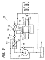
- a fuel supply pump 1 referred to simply as “supply pump” hereinafter, is applied to, for example, a common-rail fuel injection system IS of an internal combustion engine, such as diesel engine.
- the common-rail fuel injection system IS has a common rail CR for accumulating high-pressure fuel therein, and a plurality of electromagnetic fuel injectors 11...11 communicated with the common rail CR, respectively.
- the common-rail fuel injection system is configured that, in response to a command from an ECU (not shown), the high-pressure fuel in the common rail CR is injected by each of the injectors 11, and the injected high-pressure fuel is supplied to each cylinder of the internal combustion engine at a predetermined period.
- the supply pump 1, as shown in Fig. 1, constitutes the common-rail fuel injection system IS, and is served as a high-pressure supply pump for highly pressurizing the fuel in a fuel tank 12 to supply the high-pressurized fuel to the common rail CR.
- the supply pump 1 is composed of a pump element 2 configured to highly pressurize the fuel to supply the highly pressurized fuel to the common rail CR, and a control valve 3 for controlling the flow rate of the fuel supplied to the pump element 2.
- the supply pump 1 is also composed of a low-pressure feed pump 13 with an inlet and an outlet, which is referred to simply as "feed pump",
- the inlet of the feed pump 13 is connected to a fuel supply path P1, and the fuel supply path P1 is connected to an inside of the fuel tank 12 to be communicated therewith.
- the outlet of the feed pump 13 is connected to a fuel supply path P2, and the fuel supply path P2 is connected to the pump element 2.
- the control valve 3 is provided in the fuel supply path P2.
- the feed pump 13 is configured to pump the fuel from the fuel tank 12 through the fuel path P1 and supply the pumped fuel through the fuel path P2 and the control valve 3 to the pump element 2.
- the feed pump 13 may be integrally fit to the supply pump 1, or may be separately provided to either the fuel tank 12 or a fuel path from the fuel tank 12 to the control valve 3.
- the feed pump 13 may be rotatably driven by the internal combustion engine, another electrical motor, or a hydraulic actuator.
- the pump element 2 is composed of a plunger 21, a cylinder 22 in which the plunger 21 is contained to be reciprocable in the axial direction, and a compressing chamber 23 formed among inner peripheral surfaces 22a of one end portion of the cylinder 22 and one end surface 21a of the plunger 21.
- the fuel supply path P2 is communicated with the inlet 23a of the compressing chamber 23.
- the fuel accumulated in the fuel tank 12 is pumped by the pump operation of the feed pump 13 through the fuel supply path P1, and the pumped fuel is supplied through the fuel supply path P2 and the control valve 3 to the compressing chamber 23.
- the fuel in the compressing chamber 23 is compressed by the reciprocation of the plunger 21 to be highly pressurized, so that the high-pressurized fuel is outputted from the outlet 23b of the compressing chamber 23 to an output line L1.
- a check valve 24 is provided so that the high-pressurized fuel is supplied through the check valve 24 to the common rail CR. The check valve 24 prevents the high-pressurized fuel from flowing backward to the compressing chamber 23.
- a check valve 25 is provided in the fuel supply path P2 between the inlet 23b of the compressing chamber 23 and the control valve 3. The check valve 25 prevents the highly pressurized fuel from flowing backward from the compressing chamber 23 to the control valve 3.
- the supply pump 1 is also composed of a plunger driving unit 4 mechanically connected to the plunger 21 for driving the plunger 21 so that the plunger 21 reciprocates in the axial direction in the cylinder 23.
- the plunger 21 is provided at its other end portion, which is opposite to the compressing chamber side, with a plunger head 26.
- the plunger head 26 has a slide surface slidably contacted to a slide surface of the plunger driving unit 4.
- the plunger head 26 is biased by a spring 27 so that the slide surface of the plunger head 26 is contacted to the slide surface of the plunger driving unit 4.
- the plunger driving unit 4 is provided with a driving shaft 41, a cam 42, and a cam ring 43.
- the driving shaft 41 is rotatably supported around its axial direction by bearings B1 and B2, mechanically connected to a crank shaft (not shown) of the internal combustion engine so that the driving shaft 41 is rotatably driven by the rotation of the crank shaft of the internal combustion engine.
- the cam 42 is eccentrically attached to the driving shaft 41 so that the cam 42 revolves around the driving shaft 41 by the rotation thereof.
- the cam ring 43 contains the cam 42 through a metal bush so that the cam ring 43 revolves around the driving shaft 41 by the rotation of the driving shaft 41.
- the cam ring 43 has an outer peripheral surface 43a corresponding to the slide surface of the plunger driving unit 4.
- the plunger driving unit 4 is also composed of a pump-cam chamber 44 in which a part of the driving shaft 41, the cam 42, and the cam ring 43 are contained.
- the supply pump 1 is also provided with a lubricating path 45 that is branched from the fuel supply path P1 and communicated with the pump-cam chamber 44.
- a part of the fuel exhausted from the feed pump 13 is supplied through the lubricating path 45 to the pump-cam chamber 44.
- the part of the fuel allows the slide portions of the cam ring 43 and the plunger head 26, those of the metal bush and the cam 42, and the bearings B1 and B2 of the driving shaft 41 to be cooled and lubricated, respectively.
- a throttle 46 is provided in the lubricating path 45 so that it controls the flow rate of the fuel supplied to the pump-cam chamber 44.
- the supply pump 1 is also composed of an overflow path 47 connected to the pump-cam chamber 44 to be communicated therewith.
- the overflow path 47 is connected to a common drain line DL of the injectors 11 and to a fuel reflux path 14 communicated with the fuel tank 12.
- the part of fuel used as the slide portion lubricant flows through the overflow path 47 into the reflux path 14, and excessive fuel returned from the injectors 11 through the drain line DL also flow into the reflux path 14.
- the part of the fuel and the excessive fuel flow together through the reflux path 14 and are returned into the fuel tank 12.
- control valve 3 is operative to control the flow rate of the fuel supplied from the feed pump 13 through the fuel supply path P2 to the compressing chamber 23.
- This fuel-rate control operation of the control valve 3 is carried out so that the control valve 3 controls the valve opening of its valve member in response to a command from the ECU to keep the fuel pressure in the common rail CR at a predetermined pressure.
- the control valve 3, therefore, allows the amount of the high-pressurized fuel supplied to the common rail CR to be controlled.
- control valve 3 as shown in Figs. 2A and 2B, is provided with a needle 31 as the valve member, and a tubular housing 32 having an inner chamber 32a in which the needle 31 is contained.
- the housing 32 has at its one end wall 32b with a suction port 35 formed therethrough.
- the suction port 35 is connected to the fuel supply path P1 so that the fuel supplied from the feed pump 13 is sucked through the suction port 35 into the inner chamber 32a.
- the housing 32 also has at its peripheral side wall 32c a discharge port 36 connected through the fuel supply path P2 to the compressing chamber 23.
- the control valve 3 is also provided with a spring 33 contained in the inner chamber 32a and interposed between the one end wall 32b and the needle 31.
- the spring 33 axially urges the needle 31 to an opening direction away from the discharge port 36.
- the control valve 3 is further provided with a coil 34 that causes, when energized, magnetomotive force and the magnetomotive force allows the needle 31 to be biased to a closing direction opposite to the opening direction.
- the suction port 35 is constantly opened.
- the needle 31 When the energization of the coil 34 is stopped based on the control of the ECU, the needle 31 is urged by the elastic force of the spring 33 to move away from the discharge port 36, so that the discharge port 36 is fully opened. That is, the control valve 3 is fully opened when no energization of the coil 34 is performed.
- the energization of the coil 34 causes the magnetomotive so that the magnetomotive biases the needle 31 to the closing direction based on the current value applied in the coil 34.
- the control valve 3 allows the valve opening of the control valve 3 to be controlled according to the current value applied in the coil 34.
- the fuel supply pump 1 is provided with a fuel relief path 38 branched from the part of the fuel supply path P2 that connects the discharge port 36 to the compressing chamber 23, which is referred to as fuel supply path 37.
- the fuel relief path 38 is disposed in substantially parallel to the lubricating path 45 and connected to pump-cam chamber 44. That is, the fuel flowing through the fuel supply path 37 passes through the fuel relief path 38 to flow into the pump-cam chamber 44.
- a throttle 39 is provided in the fuel relied path 38 so that it controls the flow rate of the fuel supplied to the pump-cam chamber 44 through the fuel relief path 38.
- the excessive fuel is relieved through the fuel relief path 38 into the pump-cam chamber 44. That is, in the control valve 3, after the valve opening of the needle 31 is controlled based on the control of the ECU, the fuel is leaked through the minute clearance between the needle 31 and the housing 32 so that the fuel is excessively supplied to the fuel supply path 37.
- the excessive fuel accumulated in the power supply path 37 passes through the fuel relief path 38 to be relieved into the pump-cam chamber 44.
- the throttle 39 allows the fuel rate flowing through the fuel relief path 38 to be controlled, making it possible to relieve only the excessive fuel into the pump-cam chamber 44.
- the fuel relief path 38 is branched from the power supply path 37 in substantially parallel to the lubricating path 45 to be connected to the pump-cam chamber 44, the fuel relief path 38 allows the excessive fuel accumulated in the power supply path 37 to be relieved into the pump-cam chamber 44 that is close to the power supply path 37.
- the supply pump 1 has no need to increase the fuel relief path 38 in length and to bend it at its many mid-points, making it possible to improve the workability of the fuel relief path 38.
- the throttle 39 controls the fuel rate flowing through the fuel relief path 38 into the pump-cam chamber 44, preventing the fuel in the fuel supply path 37 from excessively flowing into the pump-cam chamber 44. As a result, it is possible to prevent the amount of fuel supplied to the compressing chamber 23 from decreasing.
- a supply pump 1A is provided with a fuel relief path 38A branched from the fuel supply path 37 and connected to the lubricating path 45 at its downstream side of the throttle 46.
- the supply pump 1A is also composed of a throttle 39 disposed in the fuel relied path 38A so that it controls the flow rate of the fuel supplied to the pump-cam chamber 44 through the fuel relief path 38A.
- the fuel relief path 38A is joined to the downstream side of the lubricating path 45 with respect to the throttle 46, negative pressure generated to the lubricating path 45 at its downstream side of the throttle 46 allows the excessive fuel in the fuel supply path 37 to be sucked through the fuel relief path 38A into the lubricating path 45. This results in that the excessive fuel is relieved through the lubricating path 45 into the pump-cam chamber 44.
- the throttle 39 allows the fuel rate flowing through the fuel relief path 38A to be controlled, making it possible to suck only the excessive fuel into the pump-cam chamber 44 by the negative pressure, thereby relieving the sucked excessive fuel into the pump-cam chamber 44.
- the fuel relief path 38A is branched from the power supply path 37 and connected to the downstream side of the lubricating path 45 with respect to the throttle 46, the fuel relief path 38A permits the excessive fuel accumulated in the power supply path 37 to be relieved into the lubricating path 45 that is close to the power supply path 37.
- the supply pump 1A has no need to increase the fuel relief path 38A in length and to bend it at its many mid-points, making it possible to improve the workability of the fuel relief path 38A.
- the fuel relief 38A is not directly connected to pump-cam chamber 44 but is connected to the downstream side of the throttle 46 so that the negative pressure allows the excessive fuel to be sucked into the lubricating path 45, which can restrain the influence of back pressure from the injectors 11.
- the back pressure occurs due to the returns of the excessive fuels from the injectors 11 to the fuel tank 12 through the fuel reflux path 14, so that the pressure of the lubricating fuel in the pump-cam chamber 44 is affected by the back pressure through the overflow path 47.
- the discharge pressure of the feed pump 13 at the upstream side of the throttle 46 is far larger than the back pressure from the injectors 11. This results in that the lubricating fuel constantly flows in the lubricating path 45 from the feed pump 13 to the pump-cam chamber 44 so that the negative pressure is constantly caused at the downstream side of the throttle 46.
- the negative pressure therefore, allows the excessive fuel in the fuel supply path 37 to be sucked into the lubricating path 45 while it substantially frees of influence from the back pressure.
- the throttle 39 controls the fuel rate flowing through the fuel relief path 38A into the pump-cam chamber 44, preventing the fuel in the fuel supply path 37 from excessively flowing into the pump-cam chamber 44. As a result, it is possible to prevent the amount of fuel supplied to the compressing chamber 23 from decreasing.
- the supply pumps 1 and 1A are applied to the common-rail fuel injection system, but the present invention is not limited to the application. That is, the supply pumps 1 and 1A may be applied to a jerk fuel injection system that directly supplies the high-pressurized fuel supplied from the supply pump 1, 1A to each cylinder of the internal combustion engine through the injectors 11.
- the throttle 39, 39A is provided in the fuel relief path 38, 38A, but the throttle 39, 39A may be not necessarily provided in the fuel relief path 38, 38A.
- throttles 39 (39A) and 46 orifices, chokes or other similar members may be used.
- a fuel relief path relieves a part of fuel, which is supplied through a part of fuel supply path connected between a control valve and a compressing chamber of a pump element, into a slidably contact portion between a plunger of the pump element and a plunger driving unit.
Landscapes
- Engineering & Computer Science (AREA)
- Mechanical Engineering (AREA)
- General Engineering & Computer Science (AREA)
- Chemical & Material Sciences (AREA)
- Combustion & Propulsion (AREA)
- Fuel-Injection Apparatus (AREA)
Abstract
Description
Claims (6)
- A fuel supply pump for pressurizing a fuel fed from a low-pressure feed pump, said fuel supply pump comprising:a pump element having a plunger and a compressing chamber, said compressing chamber being connected through a fuel supply path to the low-pressure feed pump, said fuel fed from the low-pressure feed pump being supplied to the compressing chamber through the fuel supply path, said plunger pressurizing the fuel supplied to the compressing chamber;a plunger driving unit having a driving member and a housing for reciprocating said plunger, said driving member being rotatably supported to the housing and slidably contacted to the plunger;a control member provided in the fuel supply path to control a fuel rate of the fuel fed from the low-pressure pump through the fuel supply path;a check valve provided in a part of the fuel supply path, said par of the fuel supply path being connected between the control member and the compressing chamber, said check valve preventing the fuel supplied to the compressing chamber from flowing backward to the control member;lubricating means for supplying a part of fuel to a slidably contact portion between the plunger and the plunger driving unit, said part of fuel being fed from the low-pressure feed pump through the fuel supply path; andfuel relief means for relieving a part of fuel to the slidably contact portion between the plunger and the plunger driving unit, said part of fuel being supplied through the part of the fuel supply path to the compressing chamber.
- A fuel supply pump according to claim 1, wherein said fuel relief means is disposed to be substantially parallel to the lubricating means.
- A fuel supply pump according to claim 1, wherein said fuel relief means is provided with a throttle.
- A fuel supply pump according to claim 1, wherein said housing has an inner hollow chamber in which the slidably contact portion is contained, said fuel relief means is branched from the part of fuel supply path and connected to the housing, and said fuel relief means is communicated with the inner hollow chamber.
- A fuel supply pump for pressurizing a fuel fed from a low-pressure feed pump, said fuel supply pump comprising:a pump element having a plunger and a compressing chamber, said compressing chamber being connected through a fuel supply path to the low-pressure feed pump, said fuel fed from the low-pressure feed pump being supplied to the compressing chamber through the fuel supply path, said plunger pressurizing the fuel supplied to the compressing chamber;a plunger driving unit having a driving member and a housing for reciprocating said plunger, said driving member being rotatably supported to the housing and slidably contacted to the plunger;a control member provided in the fuel supply path to control a fuel rate of the fuel fed from the low-pressure pump through the fuel supply path;a check valve provided in a part of the fuel supply path, said par of the fuel supply path being connected between the control member and the compressing chamber, said check valve preventing the fuel supplied to the compressing chamber from flowing backward to the control member;lubricating means for supplying a part of fuel to a slidably contact portion between the plunger and the plunger driving unit, said part of fuel being fed from the low-pressure feed pump through the fuel supply path;first throttle means provided in the lubricating means for controlling the part of fuel supplied through the lubricating means; andfuel relief means for relieving a part of fuel into a downstream side of the lubricating means with respect to the first throttle means, said part of fuel being supplied through the fuel supply means to the compressing chamber.
- A fuel supply pump according to claim 5, wherein said fuel relief means is provided with second throttle means.
Applications Claiming Priority (4)
| Application Number | Priority Date | Filing Date | Title |
|---|---|---|---|
| JP2003100851 | 2003-04-03 | ||
| JP2003100851 | 2003-04-03 | ||
| JP2004037839 | 2004-02-16 | ||
| JP2004037839A JP4036197B2 (en) | 2003-04-03 | 2004-02-16 | Fuel supply pump |
Publications (2)
| Publication Number | Publication Date |
|---|---|
| EP1464826A1 true EP1464826A1 (en) | 2004-10-06 |
| EP1464826B1 EP1464826B1 (en) | 2006-08-23 |
Family
ID=32852767
Family Applications (1)
| Application Number | Title | Priority Date | Filing Date |
|---|---|---|---|
| EP04008127A Expired - Lifetime EP1464826B1 (en) | 2003-04-03 | 2004-04-02 | Fuel supply pump |
Country Status (5)
| Country | Link |
|---|---|
| US (1) | US7377753B2 (en) |
| EP (1) | EP1464826B1 (en) |
| JP (1) | JP4036197B2 (en) |
| CN (1) | CN100360790C (en) |
| DE (1) | DE602004002013T2 (en) |
Cited By (8)
| Publication number | Priority date | Publication date | Assignee | Title |
|---|---|---|---|---|
| EP1803933A1 (en) * | 2005-12-27 | 2007-07-04 | C.R.F. Societa Consortile per Azioni | High-pressure pump for a fuel, with sump in communication with the fuel |
| ITMI20081471A1 (en) * | 2008-08-05 | 2010-02-06 | Bosch Gmbh Robert | METHOD AND HIGH PRESSURE PUMP FOR FUEL SUPPLY TO AN INTERNAL COMBUSTION ENGINE |
| EP2226491A1 (en) * | 2009-02-16 | 2010-09-08 | C.R.F. Società Consortile per Azioni | Fuel-injection system for an internal-combustion engine |
| WO2011092319A3 (en) * | 2010-01-29 | 2011-09-29 | Brp-Powertrain Gmbh & Co. Kg | Internal combustion engine fuel supply system |
| ITMI20102091A1 (en) * | 2010-11-11 | 2012-05-12 | Bosch Gmbh Robert | PUMPING GROUP FOR FUEL SUPPLEMENTATION, PREFERABLY GASOIL, TO AN INTERNAL COMBUSTION ENGINE |
| GB2540549A (en) * | 2015-07-20 | 2017-01-25 | Delphi Int Operations Luxembourg Sarl | Novel fuel pump design |
| WO2018091488A1 (en) * | 2016-11-17 | 2018-05-24 | Delphi Technologies Ip Limited | High pressure fuel pump with venturi flow circuit |
| EP3604790A1 (en) * | 2010-02-26 | 2020-02-05 | Hitachi Automotive Systems, Ltd. | High-pressure fuel supply pump |
Families Citing this family (22)
| Publication number | Priority date | Publication date | Assignee | Title |
|---|---|---|---|---|
| JP3915718B2 (en) * | 2003-03-11 | 2007-05-16 | 株式会社デンソー | Fuel supply pump |
| JP4036197B2 (en) * | 2003-04-03 | 2008-01-23 | 株式会社デンソー | Fuel supply pump |
| DE602005014283D1 (en) * | 2004-09-24 | 2009-06-10 | Denso Corp | Valve for flow control |
| US7892304B2 (en) * | 2004-12-17 | 2011-02-22 | Texaco Inc. | Apparatus and method for controlling compressor motor speed in a hydrogen generator |
| DE102005027851A1 (en) * | 2005-06-16 | 2006-12-21 | Robert Bosch Gmbh | Fuel injection system for an internal combustion engine |
| DE102007000855B4 (en) * | 2006-12-27 | 2020-06-10 | Denso Corporation | Fuel delivery device and storage fuel injection system having this |
| ATE487053T1 (en) * | 2008-03-04 | 2010-11-15 | Magneti Marelli Spa | COMMON RAIL DIRECT INJECTION ARRANGEMENT WITH A SHUT-OFF VALVE FOR CONTROLLING THE DELIVERY OF A HIGH PRESSURE FUEL PUMP |
| JP4930521B2 (en) * | 2009-02-02 | 2012-05-16 | 株式会社デンソー | Fuel supply device |
| US8776764B2 (en) | 2011-01-04 | 2014-07-15 | Ford Global Technologies, Llc | Fuel system for a multi-fuel engine |
| EP2780576B1 (en) * | 2011-11-17 | 2021-03-24 | Stanadyne LLC | Auxiliary pressure relief valve in single piston fuel pump |
| JP5459330B2 (en) * | 2012-01-31 | 2014-04-02 | 株式会社デンソー | Fuel supply pump |
| US9587578B2 (en) | 2013-12-06 | 2017-03-07 | Ford Global Technologies, Llc | Adaptive learning of duty cycle for a high pressure fuel pump |
| US9458806B2 (en) | 2014-02-25 | 2016-10-04 | Ford Global Technologies, Llc | Methods for correcting spill valve timing error of a high pressure pump |
| US9243598B2 (en) | 2014-02-25 | 2016-01-26 | Ford Global Technologies, Llc | Methods for determining fuel bulk modulus in a high-pressure pump |
| US9874185B2 (en) | 2014-05-21 | 2018-01-23 | Ford Global Technologies, Llc | Direct injection pump control for low fuel pumping volumes |
| US9989022B2 (en) * | 2015-12-09 | 2018-06-05 | Delphi Technologies Ip Limited | Fuel system for an internal combustion engine and method of operating |
| CN107795419B (en) * | 2016-09-07 | 2021-06-01 | 罗伯特·博世有限公司 | High pressure fuel pump |
| CN106762297A (en) * | 2016-12-31 | 2017-05-31 | 南岳电控(衡阳)工业技术股份有限公司 | A kind of single cylinder co-rail fuel feed pump of the fuel-displaced control formula of high pressure |
| DE102018103252B4 (en) * | 2018-02-14 | 2022-01-20 | Danfoss Power Solutions Gmbh & Co. Ohg | Process and device for venting the intake side of an artificially commutated hydraulic pump |
| WO2022031820A1 (en) * | 2020-08-04 | 2022-02-10 | Stanadyne Llc | High-pressure gdi pump with low-pressure bypass |
| US11536233B2 (en) | 2020-09-15 | 2022-12-27 | Delphi Technologies Ip Limited | Fuel system for an internal combustion engine |
| IT202100010568A1 (en) * | 2021-04-27 | 2022-10-27 | Bosch Gmbh Robert | PUMP UNIT FOR SUPPLYING FUEL TO AN INTERNAL COMBUSTION ENGINE |
Citations (10)
| Publication number | Priority date | Publication date | Assignee | Title |
|---|---|---|---|---|
| GB1042259A (en) * | 1962-12-19 | 1966-09-14 | Bosch Gmbh Robert | Improvements in fuel injection apparatus for internal combustion engines |
| DE19829217A1 (en) * | 1997-06-30 | 1999-01-07 | Unisia Jecs Corp | Variable fuel pump for vehicle |
| DE19742180A1 (en) * | 1997-09-24 | 1999-03-25 | Siemens Ag | IC engine fuel-injection system |
| DE19943160A1 (en) * | 1998-09-10 | 2000-03-16 | Denso Corp | Fuel injection pump for supplying high pressure fuel to internal combustion engine comprises pump housing, cylinder and cavity arranged concentrically to each other in pump housing |
| EP1022458A2 (en) * | 1999-01-12 | 2000-07-26 | Lucas Industries Limited | Fuel system |
| US6113361A (en) * | 1999-02-02 | 2000-09-05 | Stanadyne Automotive Corp. | Intensified high-pressure common-rail supply pump |
| DE19941689A1 (en) * | 1999-09-01 | 2001-03-15 | Siemens Ag | Fuel injection device for an automobile engine |
| US20020040704A1 (en) * | 2000-10-05 | 2002-04-11 | Yoshihiko Onishi | Variable delivery fuel supply device |
| EP1241349A2 (en) * | 2001-03-15 | 2002-09-18 | Hitachi, Ltd. | Fuel supply apparatus and method of control thereof |
| US20020189438A1 (en) * | 2001-06-19 | 2002-12-19 | Katsunori Furuta | Fuel injection pump |
Family Cites Families (13)
| Publication number | Priority date | Publication date | Assignee | Title |
|---|---|---|---|---|
| DE19810867C2 (en) | 1998-03-13 | 2000-02-24 | Bosch Gmbh Robert | Fuel pump arrangement |
| JP3852756B2 (en) * | 2001-02-07 | 2006-12-06 | 株式会社デンソー | Fuel injection pump |
| JP2002322968A (en) | 2001-04-26 | 2002-11-08 | Denso Corp | Fuel supply device |
| JP4306159B2 (en) | 2001-07-09 | 2009-07-29 | 株式会社デンソー | Fuel supply device |
| ES2286288T3 (en) * | 2001-09-13 | 2007-12-01 | Ixetic Bad Homburg Gmbh | ASSISTED STEERING PUMP. |
| JP3852753B2 (en) * | 2001-12-04 | 2006-12-06 | 株式会社デンソー | Fuel injection pump |
| US6722864B2 (en) * | 2001-12-12 | 2004-04-20 | Denso Corporation | Fuel injection pump |
| JP3915718B2 (en) * | 2003-03-11 | 2007-05-16 | 株式会社デンソー | Fuel supply pump |
| JP4036197B2 (en) * | 2003-04-03 | 2008-01-23 | 株式会社デンソー | Fuel supply pump |
| JP2004316518A (en) * | 2003-04-15 | 2004-11-11 | Denso Corp | High pressure fuel supply |
| JP4207834B2 (en) * | 2003-06-27 | 2009-01-14 | 株式会社デンソー | Accumulated fuel injection system |
| US7207319B2 (en) * | 2004-03-11 | 2007-04-24 | Denso Corporation | Fuel injection system having electric low-pressure pump |
| JP4450211B2 (en) * | 2005-01-28 | 2010-04-14 | 株式会社デンソー | Fuel supply device |
-
2004
- 2004-02-16 JP JP2004037839A patent/JP4036197B2/en not_active Expired - Fee Related
- 2004-04-02 US US10/815,950 patent/US7377753B2/en active Active
- 2004-04-02 EP EP04008127A patent/EP1464826B1/en not_active Expired - Lifetime
- 2004-04-02 CN CNB2004100323786A patent/CN100360790C/en not_active Expired - Fee Related
- 2004-04-02 DE DE602004002013T patent/DE602004002013T2/en not_active Expired - Lifetime
Patent Citations (10)
| Publication number | Priority date | Publication date | Assignee | Title |
|---|---|---|---|---|
| GB1042259A (en) * | 1962-12-19 | 1966-09-14 | Bosch Gmbh Robert | Improvements in fuel injection apparatus for internal combustion engines |
| DE19829217A1 (en) * | 1997-06-30 | 1999-01-07 | Unisia Jecs Corp | Variable fuel pump for vehicle |
| DE19742180A1 (en) * | 1997-09-24 | 1999-03-25 | Siemens Ag | IC engine fuel-injection system |
| DE19943160A1 (en) * | 1998-09-10 | 2000-03-16 | Denso Corp | Fuel injection pump for supplying high pressure fuel to internal combustion engine comprises pump housing, cylinder and cavity arranged concentrically to each other in pump housing |
| EP1022458A2 (en) * | 1999-01-12 | 2000-07-26 | Lucas Industries Limited | Fuel system |
| US6113361A (en) * | 1999-02-02 | 2000-09-05 | Stanadyne Automotive Corp. | Intensified high-pressure common-rail supply pump |
| DE19941689A1 (en) * | 1999-09-01 | 2001-03-15 | Siemens Ag | Fuel injection device for an automobile engine |
| US20020040704A1 (en) * | 2000-10-05 | 2002-04-11 | Yoshihiko Onishi | Variable delivery fuel supply device |
| EP1241349A2 (en) * | 2001-03-15 | 2002-09-18 | Hitachi, Ltd. | Fuel supply apparatus and method of control thereof |
| US20020189438A1 (en) * | 2001-06-19 | 2002-12-19 | Katsunori Furuta | Fuel injection pump |
Cited By (9)
| Publication number | Priority date | Publication date | Assignee | Title |
|---|---|---|---|---|
| EP1803933A1 (en) * | 2005-12-27 | 2007-07-04 | C.R.F. Societa Consortile per Azioni | High-pressure pump for a fuel, with sump in communication with the fuel |
| US7347186B2 (en) | 2005-12-27 | 2008-03-25 | C.R.F. Societa' Consortile Per Azioni | High-pressure pump for a fuel, with sump in communication with the fuel |
| ITMI20081471A1 (en) * | 2008-08-05 | 2010-02-06 | Bosch Gmbh Robert | METHOD AND HIGH PRESSURE PUMP FOR FUEL SUPPLY TO AN INTERNAL COMBUSTION ENGINE |
| EP2226491A1 (en) * | 2009-02-16 | 2010-09-08 | C.R.F. Società Consortile per Azioni | Fuel-injection system for an internal-combustion engine |
| WO2011092319A3 (en) * | 2010-01-29 | 2011-09-29 | Brp-Powertrain Gmbh & Co. Kg | Internal combustion engine fuel supply system |
| EP3604790A1 (en) * | 2010-02-26 | 2020-02-05 | Hitachi Automotive Systems, Ltd. | High-pressure fuel supply pump |
| ITMI20102091A1 (en) * | 2010-11-11 | 2012-05-12 | Bosch Gmbh Robert | PUMPING GROUP FOR FUEL SUPPLEMENTATION, PREFERABLY GASOIL, TO AN INTERNAL COMBUSTION ENGINE |
| GB2540549A (en) * | 2015-07-20 | 2017-01-25 | Delphi Int Operations Luxembourg Sarl | Novel fuel pump design |
| WO2018091488A1 (en) * | 2016-11-17 | 2018-05-24 | Delphi Technologies Ip Limited | High pressure fuel pump with venturi flow circuit |
Also Published As
| Publication number | Publication date |
|---|---|
| EP1464826B1 (en) | 2006-08-23 |
| DE602004002013T2 (en) | 2007-02-15 |
| JP4036197B2 (en) | 2008-01-23 |
| DE602004002013D1 (en) | 2006-10-05 |
| US20040197216A1 (en) | 2004-10-07 |
| JP2004316640A (en) | 2004-11-11 |
| US7377753B2 (en) | 2008-05-27 |
| CN1536216A (en) | 2004-10-13 |
| CN100360790C (en) | 2008-01-09 |
Similar Documents
| Publication | Publication Date | Title |
|---|---|---|
| EP1464826B1 (en) | Fuel supply pump | |
| US6609500B2 (en) | Device for controlling the flow of a high-pressure pump in a common-rail fuel injection system of an internal combustion engine | |
| JP4172422B2 (en) | Fuel injection pump | |
| US7044110B2 (en) | Fuel injection device for a combustion engine | |
| JP3915718B2 (en) | Fuel supply pump | |
| US20160319795A1 (en) | High-Pressure Fuel Pump for an Internal Combustion Engine | |
| US7128054B2 (en) | Fuel injection system for an internal combustion engine | |
| US6021761A (en) | High-pressure pump for fuel delivery in fuel injection systems of internal combustion engines | |
| US7219654B2 (en) | Fuel injection device for an internal combustion engine | |
| JP4052220B2 (en) | Fuel injection pump | |
| US20120279474A1 (en) | Fuel system for an internal combustion engine | |
| US6209522B1 (en) | Variable delivery fuel supply device | |
| WO2018012211A1 (en) | High-pressure fuel supply pump | |
| US20030037768A1 (en) | Method, computer program, control and/or regulating unit, and fuel system for an internal combustion engine | |
| US11525427B2 (en) | High pressure fuel pump and fuel supply system | |
| CN104870801B (en) | High-pressure injection system | |
| JP4404056B2 (en) | Fuel injection device for internal combustion engine | |
| JP2018059436A (en) | High pressure pump device and fuel supply system | |
| JPH10184494A (en) | Fuel pressurization pump for internal combustion engine | |
| CN101371032A (en) | Fuel injection systems for internal combustion engines | |
| JP4407647B2 (en) | Fuel injection device for internal combustion engine | |
| JP4640387B2 (en) | High pressure pump and fuel supply device for internal combustion engine |
Legal Events
| Date | Code | Title | Description |
|---|---|---|---|
| PUAI | Public reference made under article 153(3) epc to a published international application that has entered the european phase |
Free format text: ORIGINAL CODE: 0009012 |
|
| AK | Designated contracting states |
Kind code of ref document: A1 Designated state(s): AT BE BG CH CY CZ DE DK EE ES FI FR GB GR HU IE IT LI LU MC NL PL PT RO SE SI SK TR |
|
| AX | Request for extension of the european patent |
Extension state: AL HR LT LV MK |
|
| 17P | Request for examination filed |
Effective date: 20041026 |
|
| 17Q | First examination report despatched |
Effective date: 20041125 |
|
| AKX | Designation fees paid |
Designated state(s): DE FR IT |
|
| GRAP | Despatch of communication of intention to grant a patent |
Free format text: ORIGINAL CODE: EPIDOSNIGR1 |
|
| GRAS | Grant fee paid |
Free format text: ORIGINAL CODE: EPIDOSNIGR3 |
|
| GRAA | (expected) grant |
Free format text: ORIGINAL CODE: 0009210 |
|
| AK | Designated contracting states |
Kind code of ref document: B1 Designated state(s): DE FR IT |
|
| PG25 | Lapsed in a contracting state [announced via postgrant information from national office to epo] |
Ref country code: IT Free format text: LAPSE BECAUSE OF FAILURE TO SUBMIT A TRANSLATION OF THE DESCRIPTION OR TO PAY THE FEE WITHIN THE PRESCRIBED TIME-LIMIT;WARNING: LAPSES OF ITALIAN PATENTS WITH EFFECTIVE DATE BEFORE 2007 MAY HAVE OCCURRED AT ANY TIME BEFORE 2007. THE CORRECT EFFECTIVE DATE MAY BE DIFFERENT FROM THE ONE RECORDED. Effective date: 20060823 |
|
| REF | Corresponds to: |
Ref document number: 602004002013 Country of ref document: DE Date of ref document: 20061005 Kind code of ref document: P |
|
| ET | Fr: translation filed | ||
| PLBE | No opposition filed within time limit |
Free format text: ORIGINAL CODE: 0009261 |
|
| STAA | Information on the status of an ep patent application or granted ep patent |
Free format text: STATUS: NO OPPOSITION FILED WITHIN TIME LIMIT |
|
| 26N | No opposition filed |
Effective date: 20070524 |
|
| PGRI | Patent reinstated in contracting state [announced from national office to epo] |
Ref country code: IT Effective date: 20080601 |
|
| REG | Reference to a national code |
Ref country code: FR Ref legal event code: PLFP Year of fee payment: 12 |
|
| REG | Reference to a national code |
Ref country code: FR Ref legal event code: PLFP Year of fee payment: 13 |
|
| REG | Reference to a national code |
Ref country code: FR Ref legal event code: PLFP Year of fee payment: 14 |
|
| REG | Reference to a national code |
Ref country code: FR Ref legal event code: PLFP Year of fee payment: 15 |
|
| PGFP | Annual fee paid to national office [announced via postgrant information from national office to epo] |
Ref country code: IT Payment date: 20190429 Year of fee payment: 16 |
|
| PGFP | Annual fee paid to national office [announced via postgrant information from national office to epo] |
Ref country code: FR Payment date: 20190418 Year of fee payment: 16 |
|
| PGFP | Annual fee paid to national office [announced via postgrant information from national office to epo] |
Ref country code: DE Payment date: 20200420 Year of fee payment: 17 |
|
| PG25 | Lapsed in a contracting state [announced via postgrant information from national office to epo] |
Ref country code: FR Free format text: LAPSE BECAUSE OF NON-PAYMENT OF DUE FEES Effective date: 20200430 |
|
| REG | Reference to a national code |
Ref country code: DE Ref legal event code: R119 Ref document number: 602004002013 Country of ref document: DE |
|
| PG25 | Lapsed in a contracting state [announced via postgrant information from national office to epo] |
Ref country code: DE Free format text: LAPSE BECAUSE OF NON-PAYMENT OF DUE FEES Effective date: 20211103 |
|
| PG25 | Lapsed in a contracting state [announced via postgrant information from national office to epo] |
Ref country code: IT Free format text: LAPSE BECAUSE OF FAILURE TO SUBMIT A TRANSLATION OF THE DESCRIPTION OR TO PAY THE FEE WITHIN THE PRESCRIBED TIME-LIMIT Effective date: 20200402 |