EP1464797B1 - Blow by gas oil separating device - Google Patents
Blow by gas oil separating device Download PDFInfo
- Publication number
- EP1464797B1 EP1464797B1 EP04003787A EP04003787A EP1464797B1 EP 1464797 B1 EP1464797 B1 EP 1464797B1 EP 04003787 A EP04003787 A EP 04003787A EP 04003787 A EP04003787 A EP 04003787A EP 1464797 B1 EP1464797 B1 EP 1464797B1
- Authority
- EP
- European Patent Office
- Prior art keywords
- oil separator
- impeller
- oil
- housing
- gas
- Prior art date
- Legal status (The legal status is an assumption and is not a legal conclusion. Google has not performed a legal analysis and makes no representation as to the accuracy of the status listed.)
- Expired - Fee Related
Links
Images


Classifications
-
- F—MECHANICAL ENGINEERING; LIGHTING; HEATING; WEAPONS; BLASTING
- F01—MACHINES OR ENGINES IN GENERAL; ENGINE PLANTS IN GENERAL; STEAM ENGINES
- F01M—LUBRICATING OF MACHINES OR ENGINES IN GENERAL; LUBRICATING INTERNAL COMBUSTION ENGINES; CRANKCASE VENTILATING
- F01M13/00—Crankcase ventilating or breathing
- F01M13/04—Crankcase ventilating or breathing having means for purifying air before leaving crankcase, e.g. removing oil
-
- F—MECHANICAL ENGINEERING; LIGHTING; HEATING; WEAPONS; BLASTING
- F01—MACHINES OR ENGINES IN GENERAL; ENGINE PLANTS IN GENERAL; STEAM ENGINES
- F01M—LUBRICATING OF MACHINES OR ENGINES IN GENERAL; LUBRICATING INTERNAL COMBUSTION ENGINES; CRANKCASE VENTILATING
- F01M13/00—Crankcase ventilating or breathing
- F01M2013/0005—Crankcase ventilating or breathing with systems regulating the pressure in the carter
-
- F—MECHANICAL ENGINEERING; LIGHTING; HEATING; WEAPONS; BLASTING
- F01—MACHINES OR ENGINES IN GENERAL; ENGINE PLANTS IN GENERAL; STEAM ENGINES
- F01M—LUBRICATING OF MACHINES OR ENGINES IN GENERAL; LUBRICATING INTERNAL COMBUSTION ENGINES; CRANKCASE VENTILATING
- F01M13/00—Crankcase ventilating or breathing
- F01M13/02—Crankcase ventilating or breathing by means of additional source of positive or negative pressure
- F01M13/021—Crankcase ventilating or breathing by means of additional source of positive or negative pressure of negative pressure
- F01M2013/026—Crankcase ventilating or breathing by means of additional source of positive or negative pressure of negative pressure with pumps sucking air or blow-by gases from the crankcase
-
- F—MECHANICAL ENGINEERING; LIGHTING; HEATING; WEAPONS; BLASTING
- F01—MACHINES OR ENGINES IN GENERAL; ENGINE PLANTS IN GENERAL; STEAM ENGINES
- F01M—LUBRICATING OF MACHINES OR ENGINES IN GENERAL; LUBRICATING INTERNAL COMBUSTION ENGINES; CRANKCASE VENTILATING
- F01M13/00—Crankcase ventilating or breathing
- F01M13/04—Crankcase ventilating or breathing having means for purifying air before leaving crankcase, e.g. removing oil
- F01M2013/0422—Separating oil and gas with a centrifuge device
- F01M2013/0427—Separating oil and gas with a centrifuge device the centrifuge device having no rotating part, e.g. cyclone
-
- F—MECHANICAL ENGINEERING; LIGHTING; HEATING; WEAPONS; BLASTING
- F01—MACHINES OR ENGINES IN GENERAL; ENGINE PLANTS IN GENERAL; STEAM ENGINES
- F01M—LUBRICATING OF MACHINES OR ENGINES IN GENERAL; LUBRICATING INTERNAL COMBUSTION ENGINES; CRANKCASE VENTILATING
- F01M13/00—Crankcase ventilating or breathing
- F01M13/04—Crankcase ventilating or breathing having means for purifying air before leaving crankcase, e.g. removing oil
- F01M2013/0438—Crankcase ventilating or breathing having means for purifying air before leaving crankcase, e.g. removing oil with a filter
Definitions
- the present invention relates to an oil separator for purifying oil mist containing crankcase ventilation gas of an internal combustion engine, comprising a housing having an inlet for the crankcase ventilation gas, an outlet for the purified gas and an oil outlet, wherein in the housing at least one rotatably driven, rotating ⁇ labscheideelement is arranged an inner surface of the oil separation element radially outwardly surrounding wall portion of the housing is formed as ⁇ lniederschlags- and oil collection surface and connected to the oil outlet, wherein the ⁇ labscheideelement is a component in the form of a fitted with blades, at the same time acting as a rotor and compressor impeller, wherein by the rotating Impeller the incoming crankcase ventilation gas is displaceable in a rotating, entrained oil mist particles with a centrifugal force acting movement and at the same time a conveying effect on the crankcase Venting gas in one direction from the inlet to the gas outlet of the oil separator is exercisable.
- WO 01/36103 A discloses a method and an apparatus for purifying gas having the characteristics indicated above.
- the device comprises a stationary housing in which a motor-driven rotor with conical Slices is stored.
- the rotor is provided with guide elements, which may take the form of curved blades.
- the function of these guide elements is to collect the liquid deposited on the conical disks into larger droplets and then spin them off in the form of these larger droplets in order to avoid a re-mixing of liquid droplets into the gas stream.
- a simultaneous function as a pump is achieved in that cause the pump-like guide elements during rotation of the rotor, a pumping action.
- An external drive motor is connected via a shaft which is guided by a gas-tight shaft seal from the outside into the housing of the device with the rotor.
- a disadvantage is considered in this known device that the passage of the shaft through the shaft seal leads to increased friction, whereby a portion of the drive energy is consumed unused, and that the shaft seal is subject to wear and therefore controlled from time to time and renewed as needed must become.
- EP 1 422 389 A shows a centrifugal separator with a housing and a non-contact rotatable therein impeller, which exerts a centrifugal force on a gas flow.
- the centrifugal force leads to a separation of oil droplets.
- the cleaned gas is passed radially inwardly around the impeller radially inwardly and then discharged through an outlet.
- the impeller may have blades that produce a centripetal flow.
- this separator has the combined functions of an oil mist separation and a delivery of the gas.
- the drive shaft of the impeller of this separator is in particular the camshaft or balance shaft of an internal combustion engine, which adversely restricts the freedom in the arrangement of the separator, since the position and course of these waves are predetermined and fixed on the machine side.
- the end of the drive shaft carrying the impeller is cantilevered. This requires a stable shaft and a good balance to avoid disturbing vibrations of the cantilever wave, which disadvantageously has a high production cost.
- a gas-tight shaft bushing can be omitted here only because the drive shaft is located in an area of the internal combustion engine through which the crankcase ventilation gas flows anyway, which further restricts the freedom in the arrangement of the separator.
- the well-known oil separator has as ⁇ labscheideelement a rotatably mounted centrifugal rotor on which radially outwardly a ring of turbine blades is mounted.
- a drive fluid in this case compressed air
- the compressed air used for the drive comes from a provided on the associated internal combustion engine turbocharger.
- turbocharger In operating conditions in which the turbocharger does not provide a sufficient amount of compressed air or only compressed air with an insufficient pressure, can be removed via a valve arrangement auxiliary compressed air from a compressed air tank, which is present on an associated vehicle for a compressed air brake system. A friction-increasing shaft passage from the housing of the oil separator to an external rotor drive is thus avoided.
- a further disadvantage is that significant amounts of air are introduced into the oil separator by the turbine-like drive of the centrifugal rotor, which can affect the pressure conditions unfavorable and can lead to a deterioration of the separation effect.
- the centrifugal rotor here preferably consists of a stack of conical plates, between which the crankcase ventilation gas flows radially from the inside to the outside. In this case, the oil droplets forming the oil mist precipitate on the surface of the individual conical plates and are thrown off there to the oil precipitation and oil collecting surface.
- the object is to provide an oil separator of the type mentioned above, which avoids the disadvantages set out above and in particular a compact design, a good conveying effect, a good separation efficiency and a reliable and long-term maintenance-free function can be achieved.
- the functions of a rotor and a compressor summarized in the oil separator according to the invention in a single, designed as an impeller component, resulting in a particularly compact design with a small size. At the same time this ensures that no external compressor or other conveyor for maintaining the flow of the crankcase ventilation gas and for maintaining a predetermined negative pressure in the crankcase is required.
- the inlet for the crankcase ventilation gas and the outlet for the purified gas can each extend axially or tangentially or in an intermediate direction according to the circumstances in the specific application.
- the outlet for the purified gas is preferably connected to the intake tract of the associated internal combustion engine.
- the oil outlet may be provided for use with gravity for the discharge of the separated oil in a geodetically deepest part of the housing; Alternatively, the oil outlet in the housing can also be higher, since the separated oil can be promoted by the rotating impeller to a higher position of the oil outlet.
- the oil outlet is pressurized by its peripheral arrangement, thereby promoting the oil drain becomes.
- the oil separator according to the invention can be used in a virtually arbitrary mounting position. An undesirable access of oil in the gas outlet and bearing points of the impeller can be prevented by appropriate design and shape of the housing.
- the impeller can be set in rotation contactlessly by a drive arranged outside the housing, as a result of which a friction-increasing, gas-tight shaft feedthrough is avoided.
- the drive is thus advantageous in a non-perfused by the crankcase ventilation gas area.
- an electric drive can be used without the risk of ignition of the potentially combustible crankcase ventilation gas.
- the oil separator is protected from damage An accumulation of oil droplets safely. This ensures a reliable and long-term maintenance-free operation of the oil separator.
- the housing and the impeller are formed in the form of a radial or axial compressor or in a mixed form of both. This ensures that the desired conveying effect is achieved to a sufficiently large extent, while at the same time ensuring that the crankcase ventilation gas is effectively displaced in the rotational movement required to separate the oil mist for generating centrifugal forces.
- this may be in the form of a multi-stage and / or a multi-flow compressor.
- this drive preferably comprises a magnetic coupling or an eddy current coupling and an electrically or hydraulically or pneumatically driven motor or derived from the internal combustion engine mechanical drive. All parts of the engine are thus outside of the perfused by the crankcase ventilation gas inside the oil separator.
- the transmission of the driving force to the impeller is carried out contactlessly via the magnetic coupling or the eddy current coupling through a wall of the housing of the oil separator, wherein this wall is preferably an end-side or peripheral side wall. In this way, any explosion or fire hazard is avoided by sparks within an electric drive motor, since the possibly flammable crankcase ventilation gases are not in the range of, for example, electric Drive motor can get.
- a transmission gear preferably with a fixed gear ratio, be provided in order to operate on the one hand the engine and on the other hand, the impeller with a respective favorable, mutually different speed.
- a good separating effect of the oil separator can be expected in practice at speeds of the impeller in a range between about 5,000 and 15,000 1 / min.
- the non-contact drive of the impeller may include an integrated brushless electric motor.
- the housing of the oil separator can remain completely closed, so that even in this embodiment can be dispensed with friction-increasing shaft seals. Since the electric motor is a brushless motor, there is also no risk of ignition of the crankcase ventilation gas, if this should constitute an ignitable mixture. Thus, the required safety is guaranteed here, too, despite an electric drive.
- the impeller can be driven at a constant speed. This ensures in particular that the drive can be kept very simple.
- an alternative embodiment of the oil separator suggests in this regard that the impeller can be driven with a variable, each present operating state of the internal combustion engine adapted speed. Although a somewhat more expensive drive is required for this embodiment, but at the same time an improvement in the efficiency of the oil separator and a Targeted influence of the pressure in the crankcase can be achieved.
- a development of the oil separator is specified in claim 8.
- an adjustable throttle body or (each) an adjustable combined throttle and valve member is provided in or in front of the inlet for the crankcase ventilation gas and / or in or behind the outlet for the purified gas (depending )
- an adjustable throttle body or (each) an adjustable combined throttle and valve member is provided in or in front of the inlet for the crankcase ventilation gas and / or in or behind the outlet for the purified gas (depending )
- an adjustable throttle body or (each) an adjustable combined throttle and valve member is provided.
- these organs can be used to completely block one or more flow paths for the crankcase ventilation gas or the purified gas as needed.
- This locked state is used in particular at standstill of an associated internal combustion engine in order to prevent caused by a chimney effect gas leakage and deposition of oil droplets or Kondensaten.in an associated line system and sensors provided therein for engine control and monitoring.
- crankcase ventilation gas may, if necessary, be passed through the oil separator several times, at least in partial quantities, which results in an improvement the oil separation can be achieved.
- a circulation including the crankcase is useful, for example, in a follow-up operation of the oil separator after stopping the engine. For a certain time after switching off the engine crankcase gases still occur, which can then be cleaned in the oil separator and returned to the crankcase to prevent harmful deposition of oil droplets and condensates in the gas line system and on any sensors provided therein any kind.
- the impeller is designed as an open, high-speed impeller.
- Such an impeller can be relatively easily manufactured and has a low weight, which high speeds are achieved quickly for a given drive power.
- the impeller may be designed as a closed impeller with a cover disk.
- the cover disc is achieved in particular that the crankcase ventilation gas is forcibly detected in its full volume flow through the impeller, whereby the crankcase ventilation gas issued rotation is particularly intense, which is beneficial for the separation of the oil mist by centrifugal force.
- the impeller can be designed on the inflow side with precursors.
- a further development of the oil separator is specified in claim 14.
- a fixed and / or rotating with the rotating ⁇ labscheidelement or the impeller filter body preferably made of a foam or a knitted fabric is arranged.
- a conventional oil separation element is integrated in the form of the filter body in the oil separator, which complement the deposition effects advantageous.
- Another measure for targeted and, if necessary, variable influencing the flow conditions in the oil separator is that the impeller fixed or adjustable Vorleitschaufeln upstream and / or fixed or adjustable Nachleitschaufeln can be connected downstream.
- the impeller is rotatably mounted on a fixed shaft or fixed on a rotatably mounted shaft, that the impeller is mounted flying or tensioned and that as a bearing for the rotatable mounting of the impeller or the shaft at least a plain bearing or rolling bearing or air cushion bearing or magnetic bearing is provided.
- a flying storage is more appropriate for shorter-built wheels; a tense bearing is particularly useful for wheels with greater axial length.
- Sliding or rolling bearings are common and inexpensive bearings that can be used in the market.
- air cushion bearings or magnetic bearings are somewhat more expensive, but are characterized by a particularly low friction, so that hereby a particularly good drive efficiency can be achieved.
- the impeller In unilaterally equipped with blades wheels it may happen during operation that forms a pressure difference between the two sides of the impeller, which leads to an axial force on the impeller. This can lead to increased friction in the bearings of the impeller or the associated shaft. In order to exclude this increase in friction, it is provided that the impeller is equipped with blades on both sides or that in one side equipped with blades impeller in this at least one equipped with blades side of the impeller is attached to the other side pressure equalization opening. As a result, pressure differences between the two sides of the impeller can not arise, which caused by differences in pressure axial forces are excluded on the impeller.
- the housing is made of two housing parts with a circumferential in the ⁇ lniederschlags- and oil collecting surface housing separation plane.
- the housing parts can be advantageously produced as injection molded parts made of plastic or light metal and joined together with the inclusion of the impeller to the housing. Due to the course of the housing separation plane in the oil precipitation and oil collection surface is also the cheap way to gain access to the oil precipitation and oil collection surface and the impeller by separating the housing parts to clean them as needed as part of a maintenance of the oil separator.
- a further development of the oil separator is specified in claim 20. It is provided to achieve a particularly compact design with a reduced number of parts of the oil separator, that is a part of the housing as an integral part of the associated internal combustion engine, in particular of the crankcase or control housing or cylinder head cover is formed. The required installation space is so small and it is advantageous short flow paths.
- this embodiment of the oil separator provides that it is provided with a heating means for heating at least the wall area of the housing serving as the oil precipitation and oil collecting surface and / or heating the rotating oil separator or impeller Part of the housing is used.
- a further development of the oil separator is specified in claim 22. It is provided for the oil separator, that this is associated with a control or control device with which the function of the oil separator at least by varying the rotational speed of the rotating oil separator or impeller the current operating state of the internal combustion engine, preferably by accessing a in an electronic engine control and - rule unit digitally stored engine map, is adaptable. With this control or control device can be achieved that in different operating conditions of the internal combustion engine depending on the oil separator is influenced in its operation, that on the one hand always a good efficiency in the oil mist separation from the crankcase ventilation gas is achieved and on the other hand, the pressure in Crankcase of the associated internal combustion engine is held within a predetermined pressure range.
- the rule or Control unit preferably a permanently connected diagnostic unit or an interface for on-demand connection of a diagnostic unit.
- in or on the oil separator sensors are provided with those relevant to the operation of the oil separator parameters, in particular actual speed of the rotating oil separator or impeller, gas pressure before and / or behind the rotating oil separator or impeller, gas flow through the oil separator, the temperature of the incoming crankcase ventilation gas and / or the outflowing clean gas and / or the oil separator itself or its drive, can be detected and forwarded to the control or control device, and that in or on the oil separator actuators are provided with which the operation of Adjustable.
- Organs influencing the oil separator in particular the drive of the rotating oil separation element or impeller or the throttle elements or the throttle and valve members or the guide vanes, are adjustable.
- the control or control device can always detect the current operating state of the oil separator and if necessary via the actuators influence the oil separator in its function and operation so that always an optimal or near-optimal mode of operation is guaranteed, the current operating state of the associated internal combustion engine is adapted.
- the oil separator or the drive of the oil separator can have a cooling device which can be switched on or off in accordance with the detected temperatures.
- the crankcase ventilation gas which flows to the oil separator or flows through the oil separator or flows away from the oil separator, gases, e.g. Noble gases, can be supplied.
- gases e.g. Noble gases
- the separation efficiency of the oil separator can be increased or influenced, for example, by operating an associated internal combustion engine by passing the crankcase ventilation gas, after passing through the oil separator, together with the supplied gas into the engine Intake tract of the associated internal combustion engine is initiated.
- the crankcase ventilation gas which flows through the oil separator, and / or at least a part of the oil separator is displaceable in an ultrasonic vibration.
- the ultrasonic vibration By the ultrasonic vibration, the deposition of the oil droplets from the crankcase ventilation gas can be positively influenced.
- the flowability of the deposited oil is increased so that it leaves the oil separator faster through the oil outlet.
- crankcase ventilation gas which flows through the oil separator
- the conditioning device can be charged electrostatically by means of the conditioning device.
- the separation of oil droplets from the entrained in the crankcase ventilation gas oil mist can be positively influenced, as is known per se of pure electrostatic precipitators, however, have a considerable size.
- the electrostatic charge is used in addition to reinforce the separation effect generated by the centrifugal force yet.
- an oil separator which is characterized in that it comprises a plurality of parallel-connected oil separator according to one of the preceding claims. This makes it possible, depending on the size of an associated internal combustion engine to use one or more oil separators or depending on the instantaneous power of the internal combustion engine to activate a more or less large number of parallel oil separators, the number of active oil separators depending on the amount of just incurred, too de-oiling crankcase ventilation gas.
- the plurality of oil separators are identical to each other and are modularly connected to one another in a desired number. This is advantageously achieved that in the best case, the oil separator must be constructed and built only in one embodiment and that it is then used as needed simply or repeatedly on an internal combustion engine, which is very easy to connect with each other by the modularly connectable oil separator.
- the materials used for the oil separator must of course be resistant to the thermal, mechanical and chemical influences that occur in practice. This can be done preferably high quality plastics and light metals.
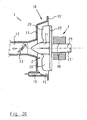
- an oil separator 1 comprises a housing 10 which is formed from two housing parts 11, 12.
- the housing parts 11, 12 lie sealingly against one another along a parting plane 10 'with the interposition of a sealing element and are connected to one another in a suitable manner, for example by means of screws.
- an impeller 2 is rotatably mounted on a housing-fixed shaft 17, for which purpose a sliding bearing 24 is used, which is arranged between the housing-fixed shaft 17 and a part of the impeller 2 forming hub 21.
- the impeller 2 has a base plate 22 which is occupied by circumferentially spaced blades 20.
- the impeller 2 in the interior of the housing 10 is set in rotation.
- the housing 10 On the left in FIG. 1, the housing 10 has an inlet 13 for crankcase ventilation gas to be liberated from oil mist, which flows in the direction of the arrow indicated in the inlet 13.
- an outlet 14 is shown for purified crankcase ventilation gas, through which the gas flows in the direction of the arrow.
- an adjustable throttle body 13 ' is arranged in the form of a pivotable throttle valve, with which the free flow area of the inlet 13 for the crankcase ventilation gas is variable.
- the inflowing crankcase ventilation gas is rotated by the impeller 2 as it rotates by means of the rotary drive 3, whereby a centrifugal force is applied to the oil droplets entrained in the crankcase ventilation gas.
- the impeller 2 acts with its blades 20 at the same time as a centrifugal rotor and as a compressor, the latter serving to generate a conveying effect on the gas in the direction from the inlet 13 to the outlet 14.
- a non-contact electric drive 3 is used to generate the rotational movement of the Impeller 20 about its axis of rotation 29.
- the non-contact electric drive 3 is formed by an electric motor 30 which is located in a separate housing portion 18 outside the interior of the oil separator 1. Via a motor shaft 31, an arrangement of permanent magnets 35 is rotatably connected to the motor 30. When the electric motor 30 is switched on, this arrangement of permanent magnets 35 rotates directly on the outside of the right-hand housing part 12 of the housing 10. Opposite this arrangement of permanent magnets 35 is an arrangement of second permanent magnets 25 in the interior of the housing 10 on the rear side of the base disk 22 Impeller 2 connected, for example, glued, are.
- the magnetic coupling thus formed takes the impeller 2 with the electric motor 30 and thus ensures the desired rotational movement of the impeller 2, without requiring a passage of a rotatable shaft is required by a wall of the housing 10.
- the electrical energy required for the operation of the electric motor 30 is supplied via an electric cable 34, which is shown only in sections here. Instead of the permanent magnets 25, 35 and hysteresis material magnets can be used.
- FIG 2 shows the oil separator of Figure 1, which is now supplemented by several components and in which the electric drive 3 is modified.
- the housing 10 with its two housing parts 11, 12 and the separating plane 10 'running between them corresponds to the embodiment according to FIG. 1.
- the impeller 2 is also identical to the embodiment according to FIG. 1.
- the inlet 13 is provided with two sensors 71, with which the temperature and the pressure of the crankcase ventilation gas in the inlet 13 of the oil separator 1 can be detected.
- the inlet 13 may also be arranged tangentially, as indicated by dashed lines at the top right of the continuously drawn inlet 13.
- the outlet 14 for purified crankcase ventilation gas is here, as in Figure 1, tangentially upwardly from the housing 10 from.
- an adjustable throttle body 14 ' also here in the form of a pivotable throttle valve, is arranged.
- a flow measuring 72 is further arranged, which has the form of a displaceable by the flowing gas in rotation measuring element.
- the flow sensor also the sensor 72 'shown separately in Figure 2 above, which is formed here by a heated wire, which cools more or less according to the respective present gas flow, whereby its electrical resistance varies.
- a sensor arrangement 71 is provided at the outlet 14, with which the temperature and the pressure of the cleaned crankcase ventilation gas in the outlet 14 can be detected.
- a further sensor arrangement is arranged on the right-hand side of the housing 12 in the lower right-hand corner of FIG. 2 and communicates with the interior of the housing 10 in order to control the position therein To detect temperature and the pressure of the crankcase ventilation gas.
- a control or regulation device 7 By means of this regulation or control device 7, the drive 3 of the Oil separator 1 are controlled so that always the best possible separation efficiency and a desired pressure in the crankcase of an associated internal combustion engine, which is connected to the inlet 13, is reached ..
- the adjustable throttle body 14 'of the control or control unit 7 from in appropriate Be adjusted.
- the drive 3 is not carried out in the oil separator 1 according to Figure 2 with an electric motor, but with a coil assembly 33 which is arranged itself fixed, but can generate a rotating electromagnetic field.
- This rotating electromagnetic field acts through a wall of the right housing part 12 through the mounted on the impeller 2 permanent magnets 25, whereby the rotary drive of the impeller 2 is effected.
- the drive 3 is connected to the control or control unit 7 in connection.
- an electrical cable 34 shown only in sections is also used here.
- crankcase vent gas flowing in through the inlet 13 is set in strong rotation, which by centrifugal force conveys the oil droplets contained in the gas to the oil precipitation and oil collecting surface 15 from where the precipitated oil is discharged through the oil outlet 16 can.
- FIG. 3 of the drawing shows a view into the interior of the oil separator 1 according to FIG. 2 from left to right with the left housing part 11 removed.
- the view now points to the right-hand housing part 12 and the parting plane 10 'with the impeller 2 arranged therein.
- the base plate 22 is arranged on the front, preferably integrally formed blades 20 which have the typical curvature of compressors in their course from radially inward to radially outward.
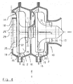
- Figure 4 shows a two-stage oil separator 1, which is characterized in that it has two wheels 2 ', 2.
- the two wheels 2 ', 2 are housed one behind the other and rotatable about a common axis of rotation 29 in the housing 10 consisting of three housing parts.
- On the right side of the housing 10 is the inlet 13 for entölendes crankcase ventilation gas.
- Radially outside From the blades 20 of the first impeller 2 ' is a first ⁇ lniederschlags- and oil collection surface 15, from the down a first oil outlet 16 goes off.
- a transfer opening 113 leads into a second part of the housing 10, in which the second impeller 2 is arranged. Also, this impeller 2 has blades 20. Radially outside of these blades 20 is also here an oil precipitation and oil collection surface 15, which also opens down into an oil outlet 16.
- FIG. 4 shows the outlet 14 for the deoiled crankcase ventilation gas.
- the drive of the two wheels 2 ', 2 takes place here together again via a non-contact drive, including the left in Figure 4 impeller 2 is equipped with an arrangement with permanent magnets 25, as explained earlier.
- the wheels 2 ', 2 are connected to each other rotationally.
- both wheels 2 ', 2 each have a supporting base plate 22nd
- FIG. 5 shows an oil separator 1, which is characterized in that it is a double-flow oil separator 1.
- This oil separator 1 is mirror-symmetrical to a plane perpendicular to the plane of the drawing center plane and has left and right each have an inlet 13 for entölendes crankcase ventilation gas.
- the housing 10 of the oil separator 1 has two housing halves, wherein in each half an impeller 2 is arranged, wherein the wheels 2 are arranged mirror-symmetrically. Towards the top, the interiors of the two parts of the housing 10 open into a common outlet 14 for the deoiled crankcase ventilation gas.
- the two wheels 2 are again rotatably mounted on a housing-fixed common shaft 17 by means of bearings 24 here.
- the drive of the wheels 2 takes place again without contact by means of an electric drive 3.
- housing 10 coils 33 are arranged, which are supplied via an electrical line 34 with a suitable voltage.
- permanent magnets 25 are again arranged in juxtaposition to the coils 33, which form the impeller-side part of the drive 3.
- an oil precipitation and oil collecting surface 15 is again formed on the inside of the respectively associated part of the housing 10. Each of these surfaces 15 open into an oil outlet 16 each.
- FIG 6 shows an oil separator 1 in which a return line 19 is provided between the outlet 14 and the inlet 13 for the crankcase ventilation gas.
- a return line 19 is provided between the outlet 14 and the inlet 13 for the crankcase ventilation gas.
- an adjustable throttle body 19 ' is arranged in the form of a pivotable throttle valve. With this throttle body 19 ', the passage cross section of the return line 19 can be adjusted as needed or completely closed.
- at least a portion of the coming out of the oil separator 1 crankcase ventilation gas from the outlet 14 can be performed again to the inlet 13, so that a portion of the gas passes through the oil separator 1 several times.
- the oil separator 1 per se is shown in Figure 6 only in external view, so that only the housing 10 with the right attached thereto drive 3 is visible.
- the arranged inside the housing 10 impeller 2 is indicated in dashed lines.
- FIG. 7 shows one embodiment of the impeller 2 in the left and in the right half.
- the impeller 2 is designed as an open impeller, wherein the blades 20 end free radially outside.
- the radially inner part of the impeller 2 forms the hub 21, in whose lower part in Figur'7 the arrangement of permanent magnets 25 is provided.
- Radially outward from the permanent magnets 25 are the coils 33 as part of the drive, in which case a coil 33 is visible.
- the impeller 2 is formed as a closed impeller.
- the blades 20 are at their remote from the hub 21 end connected by a peripheral cover plate 122 with each other.
- the right wheel 2 has a base plate 22 in which the permanent magnets 25 are mounted. Below these permanent magnets 25 is one of the coils 33 as part of the contactless electric drive of the impeller. 2
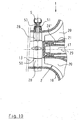
- FIG. 8 shows an oil separator 1, for which it is characteristic that next to the impeller 2 it has a precursor 26 on the inflow side and guide vanes 28 'on the outflow side.
- FIG. 8 shows the contactless electric drive 3, which is housed in its own housing part 18.
- an electrical line 34 Inside the housing part 18 is a non-rotatably connected to a motor shaft 31 of the motor 30 disc 32 in which an array of permanent magnets 35 is housed. Opposite of these permanent magnets 35, separated by a part of the housing 10 forming wall, the permanent magnets 25 of the impeller second
- Figure 9 shows an embodiment of the oil separator 1 which is characteristic of having heaters 6, 6 '.
- the housing 10 of the oil separator 1 consists here again of two housing parts 11, 12, which are connected to each other along a parting plane 10 '.
- the impeller 2 in the interior of the housing 10 is here again rotatably mounted on a housing-fixed shaft 17 by means of plain bearings 24, 24 '.
- a precursor 26 is provided here, with a part of the hub 21st the impeller 2 is connected. This part of the hub 21 is in turn firmly connected to the rest of the impeller 2, for example, welded.
- the oil precipitation and oil collecting surface 15 is here again present, which merges into the oil outlet 16 at the very bottom.
- a first heating device 6 is provided on the outside at the lower part of the housing 10 in the region of the oil precipitation and oil collecting surface 15.
- the surface 15 of the housing interior can be heated, at which the oil precipitates, whereby the oil is flowable and flows faster to the outlet 16.
- a second heating device 6 ' is provided inside the housing-fixed shaft 17 and serves to heat in the region of the bearings 24, 24' for lubrication existing lubricants and thereby reduce the bearing friction in the bearings 24, 24 '. As a result, a higher speed of the impeller 2 is achieved at a given drive power.
- FIG. 10 shows a detail of an oil separator 1, in which an arrangement of adjustable pilot vanes 28 is provided in the inlet 13.
- the arrangement comprises in the example shown a total of four Vorleitschaufeln 28, at a distance of 90 ° via the inlet 13 to the Rotary axis 29 are arranged around and radially outward.
- an actuator 5 in the form of an electric actuator, which is shown in part at the top of FIG. Via a shaft 50, an adjustment movement caused by the actuator 5 is transmitted synchronously to the individual feed vanes 28. So that no secondary flow paths for gases into the inlet 13 or out of the inlet 13 out in the region of the shaft 50 may arise, this is sealed by a gas-tight housing 51.
- the inflowing crankcase ventilation gas can be acted upon by these with a flow twist, which favorably influences the further flow guidance in the region of the vanes 20 of the rotor 2.
- the impeller 2 is only a small, near the inlet 13 lying part visible in Figure 10.
- FIG. 11 shows an embodiment of the oil separator 1, which is partially spatially integrated into the valve cover 40 'of an associated internal combustion engine 4.
- the oil outlet 16 and the impeller 2 receiving part of the housing are formed.
- the impeller 2 has here in its center a hub 21, which merges to the left in a base plate 22. With the hub 21 and the base plate 22 are the blades 20 made in one piece. Also, the permanent magnets 25 are here again in the base plate 22 attached as impeller-side part of the non-contact drive 3.
- the recess in the valve cover 40 ', in which the impeller 2 is arranged, is outwardly, i. in Figure 11 to the left, sealed by a plate-shaped part of the housing 10.
- this plate-shaped housing part On the outside, in Figure 11 so on the left side, this plate-shaped housing part is the drive 3, which is supplied via the electrical line 34 with electrical energy.
- Down the gas outlet 14 goes off for the cleaned crankcase ventilation gas.
- the gas outlet 14 extends over part of its length through the outside of the valve cover 40 'lying part of the housing 10 of the oil separator 1.
- the free end of the gas outlet 14 is formed here as a hose connection piece to which a hose for continuing the de-oiled crankcase ventilation gas can be connected.
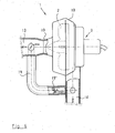
- Figure 12 shows in its left and in its right half two versions of the oil separator 1, which are each connected in series with a conventional oil separator 8 and 8 '.
- the impeller 2 is located with its blades 20 within the housing 10, in which case the axis of rotation 29 of the impeller 2 is vertical. Radially outward of the blades 20 of the impeller 2 is also the inner surface of the housing 10 as ⁇ lniederschlags- and oil collection surface 15 formed and connected to an upper left in Figure 12 visible oil outlet 16.
- the outlet 14 for the cleaned crankcase ventilation gas is located on the upper right at the top of the housing 10.
- the previously described parts of the oil separator 1 are identical for the two embodiments shown in FIG.
- the oil separator 1 shown in the left half of Figure 12 is preceded by a knitted body 81 as a conventional oil separator 8, which is arranged im.Inneren a cup-shaped lower housing part.
- the inlet 13 for the crankcase ventilation gas to be de-oiled flows laterally from the left into this lower housing part.
- the crankcase ventilation gas On its way into the region of the impeller 2, the crankcase ventilation gas must first forcibly flow through the knitted body 81 at its full volume flow, a first separation of oil droplets taking place.
- the separated in the knit body 81 oil flows under gravity down and there via an oil drain 80 from, for example, in the oil pan of an associated internal combustion engine.
- the now already partially de-oiled crankcase ventilation gas reaches the area of the impeller 2. This ensures on the one hand by centrifugal force for further separation of oil mist from the crankcase ventilation gas and on the other hand by its conveying effect for a repeal of the knitted body 81 caused differential pressure. Finally, the deoiled gas leaves the oil separator 1 through the gas outlet 14.
- the upstream conventional oil separator 8 ' is formed by a cyclone.
- tangential inlet 13 passes to be de-oiled Crankcase vent gas into the interior of the oil separator 8 'and is placed therein in a rotating vortex flow.
- some of the oil droplets are thrown by centrifugal force to the outside and deposited.
- the precipitated oil flows under gravity down to the very bottom intended oil drain 80'.
- crankcase ventilation gas passes through a central overflow from the oil separator 8 'up into the region of the impeller 2, which also ensures here for a further oil separation and on the other by its conveying effect for a cancellation of the differential pressure caused by the cyclone.
- FIG. 13 shows two embodiments of a two-stage oil separator 1, one embodiment each being shown in the upper and in the lower half of FIG.
- the first impeller 2 ' viewed in the flow direction, is provided with a co-rotating filter body 27, which can be flowed through in the radial direction by the crankcase ventilation gas, as indicated by the flow arrows.
- the now partially deoiled crankcase ventilation gas passes through the transfer opening 113 into the region of the second impeller 2, which is designed without a co-rotating filter body.
- the two wheels 2 ', 2 are arranged in a common housing 10, which here has a closed except for the transfer opening 113 dividing wall between the two wheels 2', 2.
- each impeller 2 ', 2 Radially outside of each impeller 2 ', 2 is again ever a ⁇ lniederschlägs- and oil collection surface 15, which opens down into each case an oil outlet 16.
- the first impeller 2 'seen in the flow direction is equipped with a precursor 26 with short blades.
- the impeller 2 'rotating filter body 27 which is flowed through here in the axial direction of the crankcase ventilation gas substantially.
- the base disk 22 'of the impeller 2' is gas permeable, e.g. with holes, executed.
- the left in Figure 13 side of the base plate 22 'with compressor blades 20' is occupied, which serve to generate the desired conveying action and at the same time for acting on the base disc 22 'exiting crankcase ventilation gas with a centrifugal force.
- the second impeller 2 is identical to the impeller 2 according to the upper half of FIG. 13 in the embodiment of the oil separator 1 according to the lower half of FIG.
- the gas outlet 14 for the purified crankcase ventilation gas is located at the top left in the region of the housing 10 and here has an axial outflow direction for the purified gas.
- the outlet 14 may also tangentially depart from the left upper portion of the housing 10, as indicated by dashed lines at the top of FIG.
- Figure 14 shows a closed impeller 2, which is characteristic that it has an air bearing.
- the impeller 2 has a hub part 21, which is arranged concentrically to the axis of rotation 29. With a curved course goes from the hub part 21, the base plate 22 radially outward. The blades 20 follow this course, so that the axial: inflowing crankcase ventilation gases are deflected in a radial direction.
- a housing-fixed shaft 17 Concentric with the axis of rotation 29 here a housing-fixed shaft 17 is provided, which is hollow in its interior and there forms an air passage 117. From this air passage 117 go from a plurality of transverse bores 117 ', which lead to the outer periphery of the shaft 17. On the outer circumference of the shaft 17 'sleeve-shaped bearings 24, 24' are provided in the region of the transverse bores 117. By introducing compressed air through the air passage 117 and the transverse bores 117 'in the gap region between the shaft 17 and the bearings 24, 24', an air cushion is formed there, which ensures a particularly low bearing friction. Thus, a particularly high speed of the impeller 2 is achieved at a given driving force.
- Figures 15a and 15b show in longitudinal section and in cross section two embodiments of the impeller 2 with an integrated in the region of the hub 21 non-contact drive 3 with magnetic bearings for the impeller 2. It is ever a design in the upper and in the lower half of the figure 15a and 15b.
- the impeller 2 has in both embodiments a hub portion 21, which tapers to the left-side inlet, which is not shown, steadily. Towards the right, the hub region 21 merges into the base disk 22. In the transition region from the hub part 21 to the base plate 22, the blades 20 of the impeller 2 are arranged.
- the impeller 2 is here connected to a rotatable shaft 17 ', which is rotatably mounted outside of the impeller in a manner not shown here.
- the housing 10 of the oil separator forms an annular gap-shaped space surrounding the shaft 17 '.
- the coils 33 of the non-contact electric drive 3 are housed and supplied via electrical lines 34 with electrical energy.
- the housing 10 forms an open to the shaft 17 'receiving area for the coil 33, whereby here the coils 33 are spaced from the shaft 17 only with a small air gap.
- Figures 16a and 16b show in the same representation as the figures 15a and 15b two further embodiments of the impeller 2 with contactless electric drive. 3
- the impeller 2 is executed in all versions here again with a rounded on the inlet side and otherwise hollow cylindrical hub portion 21, which merges to the right into the base plate 22.
- the blades 20 are integrally formed with the hollow cylindrical portion of the hub 21 and the base plate 22.
- an arrangement of electromagnets 33 which can be supplied with electrical energy via electrical lines 34, is seated on the outside of the housing-fixed shaft 17. Radially outward follows this arrangement of the magnets 33 a sleeve-shaped arrangement of the permanent magnets 25, in which case a small movement gap is kept free.
- the sleeve-shaped arrangement of the permanent magnets 25 is connected at its outer periphery rotationally fixed to the inner periphery of the hub 21 of the impeller 2.
- the sleeve-shaped arrangement of the permanent magnets 25 with the coil assembly 33 forms a plain bearing and at the same time the non-contact electric drive. 3
- the arrangement of the electromagnetic coils is attached to the inside of the hollow shaft 17 fixed to the housing.
- Radially outward from the hollow shaft 17 is here again a sleeve-shaped arrangement of permanent magnets 25, which is here again rotationally connected to the inner circumference of the hollow hub portion 21 of the impeller 2.
- FIG. 17 shows a section of an oil separator, the section showing the inlet 13 and a small part of the impeller 2. It is essential here that within the inlet 13 in the axial direction of an adjustable throttle body 131 is arranged.
- the throttle body 131 has taken its opening position in which it is moved away to the left, ie in the direction of the inlet 13 of the impeller 2.
- the outer circumference of the throttle body 131 is removed from an end edge 130 'of a concentric intermediate wall 130.
- Radially inwardly from this concentric partition wall 130 the path of the crankcase ventilation gas extends into the region of the impeller 2.
- Outside this concentric partition wall 31 runs an annular channel 132 as a bypass duct, which bypasses the region of the impeller 2.
- throttle body 131 ' On the left in FIG. 17, in dashed lines, an alternative form of the adjustable throttle body is indicated as throttle body 131 '.
- the throttle body 131, 131 'thus forms in this embodiment a combined throttle and valve member 13 "
- the closed position of the throttle bodies 131, 131' can be used, for example, as a shut-off function to avoid an undesired chimney effect when the internal combustion engine is at a standstill.
- FIG. 18 shows an example of the interaction of an oil separator 1 with an internal combustion engine 4 and associated further parts.
- the internal combustion engine 4 has a crankcase 40, from which a crankcase ventilation line 43 goes off. Via a throttle body 13 ', this line 43 leads to the inlet 13 of the oil separator. 1
- the impeller 2 In the oil separator 1, which is shown here only schematically, there is the impeller 2. Left of the oil separator 1, the outlet 14 is arranged for the de-oiled crankcase ventilation gas. Via a further throttle element 14 ', the outlet 14 is connected to a further gas line 44. This gas line 44 opens into an intake line 41, through which the internal combustion engine 4, the air required for combustion is supplied. Through an exhaust pipe 42, the combustion exhaust gases leave the internal combustion engine. 4
- the oil outlet 16 At the lower part of the oil separator 1 is the oil outlet 16, which is connected via an oil return line 45 to the crankcase 40 of the internal combustion engine 4. By This oil return line 45, the separated oil is returned to the oil sump in the crankcase 40.
- Figure 18 shows a return line 19 which leads from the outlet 14 to the inlet 13 of the oil separator 1.
- a check valve 19 ' is provided, which allows a gas flow only in the direction from the outlet 14 to the inlet 13 and thus a cleaning of the crankcase ventilation gas in a "small" circuit.
- the return line 19 may also be performed instead of the inlet 13 to the crankcase 40 of the internal combustion engine 4. Also in this alternative guide the return line 19 is provided in the course of the check valve 19 'to determine the desired flow direction, as is also indicated in dashed lines. In this embodiment, cleaning of the crankcase ventilation gas in a "larger" circuit including the crankcase 40 is possible. This mode of operation is e.g. after a shutdown of the internal combustion engine. 4 makes sense in a limited time lag of the oil separator 1.
- FIG. 18 also shows a regulating or control device 7, which is connected via electrical lines with sensors and actuators.
- Sensors may be, for example, elements for detecting the rotational speed of the impeller 2 or for detecting gas temperatures before or in or behind the oil separator 1 or for detecting gas pressures before or in or behind the oil separator 1.
- Actuators here are actuators for the adjustable throttle bodies 13 ', 14' and a variable drive of the impeller 2 of the oil separator 1, which by means of the control or control unit 7 can be influenced in the desired manner in their state or their position in accordance with the detected measured values.
- the aim of these measures is, on the one hand, to achieve as far as possible an oil separation from the crankcase ventilation gas and at the same time to keep the pressure in the crankcase 40 of the internal combustion engine 4 within predetermined limits.
- control or control unit 7 may be assigned a permanently connected diagnosis display 70 that can be perceived by a driver or that needs to be connected only during testing and maintenance and that can be read by the maintenance personnel.
- an arrangement with two oil separators 1 can also be used if correspondingly large amounts of crankcase ventilation gas are to be de-oiled.
- the use of two smaller oil separators 1 may be cheaper than the use of a single, correspondingly larger oil separator.
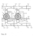
- Figure 19 shows a schematic representation of an oil separator with two identical oil separators 1, which are connected in parallel.
- Each oil separator 1 has again an impeller 2 and an inlet 13 for entölendes crankcase ventilation gas, an outlet 14 for the deoiled crankcase ventilation gas and an oil outlet 16 for the separated oil.
- the inlet 13 is in each case connected to a pipe section 43 '.
- each oil separator is connected to a respective pipe section 41 ', the in turn is connected via a line section 44 to the outlet 14 of the oil separator 1.
- the outlet 16 of each oil separator 1 is connected to a respective pipe section 45 '.
- the pipe sections 41 ', 43' and 45 'of the parallel oil separator 1 each extend in alignment with each other and are provided at their ends with connecting flanges 141, 143, 145.
- connection flanges 141, 143, 145, to which no further oil separator 1 is to be connected are to be closed by flange plates.
- a return line 19 can also be provided between the outlet 14 and the inlet 13 of the oil separator 1.
- Figure 20 shows an embodiment of the oil separator 1 with an integrated brushless electric motor 30 as a drive 3 for the impeller 2. Since the motor 30 is brushless, here no.Funken principle arise in the operation of the electric motor 30, so that the motor 30 in this embodiment can come into contact with crankcase ventilation gas without the risk of ignition of the Crankcase ventilation gas in its passage through the oil separator 1 consists.
- the oil separator 1 according to FIG. 20 corresponds to the oil separator 1 already shown and described in FIG.
- FIG. 21 shows, in a representation similar to FIG. 6, an embodiment of the oil separator 1 which is equipped with a conditioning device 9 beyond the features which are already illustrated and explained in FIG.
- the conditioning device 9 may have different designs and thus different functions.
- a supply line 90 is shown as the first embodiment of the conditioning device 9, through which a gas or gases, for example a noble gas, can be admitted into the flow of the crankcase ventilation gas which flows through the inlet 13 to the impeller 2 of the oil separator 1.
- a gas or gases for example a noble gas
- the crankcase ventilation gas can be given special properties that are more favorable for oil separation or for further use of the deoiled crankcase ventilation gas.
- the supply line 90 opens into the return line 19, which is provided here between the outlet 14 and the inlet 13 for the crankcase ventilation gas.
- a second embodiment of the conditioning device 9 comprises means for generating an electrostatic charge of the crankcase ventilation gas.
- the conditioning device comprises a voltage source 91, which is connected via not numbered lines with an electrode 91 '.
- the electrode 91 ' surrounds here a part of the inlet 13 and a part of the housing 10, namely the left housing part 11 of the oil separator 1.
Description
Die vorliegende Erfindung betrifft einen Ölabscheider für die Reinigung von Ölnebel enthaltendem Kurbelgehäuseentlüftungsgas einer Brennkraftmaschine, mit einem Gehäuse mit einem Einlaß für das Kurbelgehäuseentlüftungsgas, einem Auslaß für das gereinigte Gas und einem Ölauslaß, wobei in dem Gehäuse mindestens ein drehantreibbares, rotierendes Ölabscheideelement angeordnet ist, wobei eine innere Oberfläche eines das Ölabscheideelement radial außen umgebenden Wandbereichs des Gehäuses als Ölniederschlags- und Ölsammelfläche ausgebildet und mit dem Ölauslaß verbunden ist, wobei das Ölabscheideelement ein Bauteil in Form eines mit Schaufeln bestückten, zugleich als Rotor und Verdichter wirkenden Laufrades ist, wobei durch das rotierende Laufrad das zuströmende Kurbelgehäuseentlüftungsgas in eine rotierende, mitgeführte Ölnebelpartikel mit einer Zentrifugalkraft beaufschlagenden Bewegung versetzbar ist und zugleich eine Förderwirkung auf das Kurbelgehäuseentlüftungsgas in einer Richtung vom Einlaß zum Gasauslaß des Ölabscheiders ausübbar ist.The present invention relates to an oil separator for purifying oil mist containing crankcase ventilation gas of an internal combustion engine, comprising a housing having an inlet for the crankcase ventilation gas, an outlet for the purified gas and an oil outlet, wherein in the housing at least one rotatably driven, rotating Ölabscheideelement is arranged an inner surface of the oil separation element radially outwardly surrounding wall portion of the housing is formed as Ölniederschlags- and oil collection surface and connected to the oil outlet, wherein the Ölabscheideelement is a component in the form of a fitted with blades, at the same time acting as a rotor and compressor impeller, wherein by the rotating Impeller the incoming crankcase ventilation gas is displaceable in a rotating, entrained oil mist particles with a centrifugal force acting movement and at the same time a conveying effect on the crankcase Venting gas in one direction from the inlet to the gas outlet of the oil separator is exercisable.
Die WO 01/36103 A offenbart ein Verfahren und eine Vorrichtung zur Reinigung von Gas mit den vorstehend angegebenen Merkmalen. Die Vorrichtung umfaßt ein stationäres Gehäuse, in dem ein motorisch antreibbarer Rotor mit konischen Scheiben gelagert ist. Der Rotor ist mit Führungselementen versehen, welche die Form von gebogenen Schaufeln haben können. Die Funktion dieser Führungselemente besteht darin, die auf den konischen Scheiben niedergeschlagene Flüssigkeit zu größeren Tropfen zu sammeln und dann in Form dieser größeren Tropfen abzuschleudern, um eine erneute Einmischung von Flüssigkeitströpfchen in den Gasstrom zu vermeiden. Eine gleichzeitige Funktion als Pumpe wird dadurch erreicht, daß bei Rotation des Rotors die schaufelartigen Führungselemente eine Pumpwirkung hervorrufen. Ein externer Antriebsmotor ist über eine Welle, die durch eine gasdichte Wellendichtung von außen in das Gehäuse der Vorrichtung geführt ist, mit dem Rotor verbunden.WO 01/36103 A discloses a method and an apparatus for purifying gas having the characteristics indicated above. The device comprises a stationary housing in which a motor-driven rotor with conical Slices is stored. The rotor is provided with guide elements, which may take the form of curved blades. The function of these guide elements is to collect the liquid deposited on the conical disks into larger droplets and then spin them off in the form of these larger droplets in order to avoid a re-mixing of liquid droplets into the gas stream. A simultaneous function as a pump is achieved in that cause the pump-like guide elements during rotation of the rotor, a pumping action. An external drive motor is connected via a shaft which is guided by a gas-tight shaft seal from the outside into the housing of the device with the rotor.
Als nachteilig wird bei dieser bekannten Vorrichtung angesehen, daß die Durchführung der Welle durch die Wellendichtung zu einer erhöhten Reibung führt, wodurch ein Teil der Antriebsenergie ungenutzt verbraucht wird, und daß die Wellendichtung einem Verschleiß unterliegt und deshalb von Zeit zu Zeit kontrolliert und bei Bedarf erneuert werden muß.A disadvantage is considered in this known device that the passage of the shaft through the shaft seal leads to increased friction, whereby a portion of the drive energy is consumed unused, and that the shaft seal is subject to wear and therefore controlled from time to time and renewed as needed must become.
Die EP 1 422 389 A zeigt einen Zentrifugalabscheider mit einem Gehäuse und einem darin berührungslos drehbaren Laufrad, das auf einen Gasstrom eine Zentrifugalkraft ausübt. Die Zentrifugalkraft führt zu einer Abtrennung von Öltröpfchen. Das gereinigte Gas wird radial außen um das Laufrad herum radial nach innen weitergeleitet und dann durch einen Auslaß abgeführt. Unmittelbar radial außen vor dem Auslaß kann das Laufrad Schaufeln aufweisen, die eine Zentripetalströmung erzeugen. Damit weist dieser Abscheider die kombinierten Funktionen einer Ölnebelabscheidung und einer Förderung des Gases auf.
Die Antriebswelle des Laufrades dieses Abscheiders ist insbesondere die Nockenwelle oder Ausgleichswelle einer Brennkraftmaschine, was nachteilig die Freiheit bei der Anordnung des Abscheiders einschränkt, da Lage und Verlauf dieser Wellen maschinenseitig vorgegeben und festgelegt sind. Vorzugsweise ist das das Laufrad tragende Ende der Antriebswelle freitragend. Dies erfordert eine stabile Welle und eine gute Auswuchtung, um störende Schwingungen der freitragenden Welle zu vermeiden, was nachteilig einen hohen Fertigungsaufwand zur Folge hat. Eine gasdichte Wellendurchführung kann hier nur deshalb entfallen, weil die Antriebswelle in einem von Kurbelgehäuseentlüftungsgas ohnehin durchströmten Bereich der Brennkraftmaschine liegt, was die Freiheit bei der Anordnung des Abscheiders weiter einschränkt.The drive shaft of the impeller of this separator is in particular the camshaft or balance shaft of an internal combustion engine, which adversely restricts the freedom in the arrangement of the separator, since the position and course of these waves are predetermined and fixed on the machine side. Preferably, the end of the drive shaft carrying the impeller is cantilevered. This requires a stable shaft and a good balance to avoid disturbing vibrations of the cantilever wave, which disadvantageously has a high production cost. A gas-tight shaft bushing can be omitted here only because the drive shaft is located in an area of the internal combustion engine through which the crankcase ventilation gas flows anyway, which further restricts the freedom in the arrangement of the separator.
Ein weiterer Ölabscheider für den eingangs genannten Zweck ist aus WO 02/44530 A1 bekannt. Der bekannte Ölabscheider besitzt als Ölabscheideelement einen drehbar gelagerten Zentrifugalrotor, an dem radial außen ein Ring von Turbinenblättern angebracht ist. Über mindestens eine stationäre Antriebsfluiddüse kann ein Antriebsfluid, hier Druckluft, auf die Turbinenblätter geführt werden, um den Zentrifugalrotor in Drehung zu versetzen. Im Normalbetrieb des Ölabscheiders kommt die für den Antrieb verwendete Druckluft von einem an der zugehörigen Brennkraftmaschine vorgesehenen Turbolader. In Betriebszuständen, in denen der Turbolader keine ausreichende Menge an Druckluft oder nur Druckluft mit einem ungenügenden Druck zur Verfügung stellt, kann über eine Ventilanordnung hilfsweise Druckluft aus einem Druckluftbehälter, der an einem zugehörigen Fahrzeug für eine Druckluft-Bremsanlage vorhanden ist, entnommen werden. Eine reibungserhöhende Wellendurchführung aus dem Gehäuse des Ölabscheiders zu einem externen Rotorantrieb wird so vermieden.Another oil separator for the purpose mentioned above is known from WO 02/44530 A1. The well-known oil separator has as Ölabscheideelement a rotatably mounted centrifugal rotor on which radially outwardly a ring of turbine blades is mounted. By way of at least one stationary drive fluid nozzle, a drive fluid, in this case compressed air, can be guided onto the turbine blades in order to set the centrifugal rotor in rotation. In normal operation of the oil separator, the compressed air used for the drive comes from a provided on the associated internal combustion engine turbocharger. In operating conditions in which the turbocharger does not provide a sufficient amount of compressed air or only compressed air with an insufficient pressure, can be removed via a valve arrangement auxiliary compressed air from a compressed air tank, which is present on an associated vehicle for a compressed air brake system. A friction-increasing shaft passage from the housing of the oil separator to an external rotor drive is thus avoided.
Nachteilig ist allerdings bei diesem bekannten Ölabscheider, daß er nur an Motoren von solchen Fahrzeugen verwendbar ist, die sowohl einen Turbolader als auch eine Druckluftanlage aufweisen, was praktisch nur bei schweren Lastkraftwagen der Fall ist. Nachteilig ist weiter, daß durch den turbinenartigen Antrieb des Zentrifugalrotors erhebliche Mengen an Luft in den Ölabscheider eingeleitet werden, die die Druckverhältnisse ungünstig beeinflussen und zu einer Verschlechterung der Abscheidewirkung führen können. Der Zentrifugalrotor besteht hier vorzugsweise aus einem Stapel von konischen Platten, zwischen denen hindurch das Kurbelgehäuseentlüftungsgas radial von innen nach außen strömt. Dabei schlagen sich die den Ölnebel bildenden Öltröpfchen an der Oberfläche der einzelnen konischen Platten nieder und werden von dort auf die Ölniederschlags- und Ölsammelfläche abgeschleudert. Hiermit ist zwar eine weitgehende Abscheidung des Ölnebels erreichbar, jedoch haben nachteilig gemäß diesem Stand der Technik ausgeführte Zentrifugalrotoren praktisch keine oder nur eine sehr geringe Förderwirkung auf das Kurbelgehäuseentlüftungsgas. Damit ist eine zuverlässige Funktion dieses Ölabscheiders nur gewährleistet, wenn zwischen dem mit dem Kurbelgehäuse verbundenen Einlaß des Ölabscheiders und dem Auslaß des Ölabscheiders ein ausreichendes, die gewünschte Strömung des Kurbelgehäuseentlüftungsgases gewährleistendes Druckgefälle besteht. Zur Sicherstellung dieses benötigten Druckgefälles macht allerdings diese Schrift zum Stand der Technik keine Angaben.A disadvantage, however, in this known oil separator, that it is only suitable for engines of such vehicles, which have both a turbocharger and a compressed air system, which is practically the case only for heavy trucks. A further disadvantage is that significant amounts of air are introduced into the oil separator by the turbine-like drive of the centrifugal rotor, which can affect the pressure conditions unfavorable and can lead to a deterioration of the separation effect. The centrifugal rotor here preferably consists of a stack of conical plates, between which the crankcase ventilation gas flows radially from the inside to the outside. In this case, the oil droplets forming the oil mist precipitate on the surface of the individual conical plates and are thrown off there to the oil precipitation and oil collecting surface. Although an extensive separation of the oil mist can be achieved with this, disadvantageously centrifugal rotors designed in accordance with this prior art have virtually no or only a very slight conveying action on the crankcase ventilation gas. Thus, a reliable function of this oil separator is only guaranteed if there is sufficient between the connected to the crankcase inlet of the oil separator and the outlet of the oil separator, the desired flow of the crankcase ventilation gas pressure gradient. To ensure this required pressure gradient, however, this document makes no information about the prior art.
Ein weiterer Ölabscheider für den eingangs genannten Verwendungszweck ist aus DE 100 44 615 A1 bekannt. Auch bei diesem Ölabscheider ist ein Zentrifugalrotor vorgesehen, der als Tellerseparator, also ebenfalls mit einem Stapel von konischen Platten, ausgebildet ist. Das hier durch den Tellerseparator gebildete Ölabscheideelement ist auf einer drehbar gelagerten Achse befestigt, die aus dem Gehäuse herausgeführt ist und mit einem außerhalb des Gehäuses gelegenen Antriebsmittel gekoppelt ist.Another oil separator for the purpose mentioned above is known from DE 100 44 615 A1. Also in this oil separator, a centrifugal rotor is provided as a Tellerseparator, so also with a stack of conical plates, is formed. The oil separation element formed here by the plate separator is mounted on a rotatably mounted axle, which is led out of the housing and is coupled to a drive means located outside the housing.
Bei diesem aus dem Stand der Technik bekannten Ölabscheider wurde das Problem der geringen Förderwirkung eines als Tellerseparator ausgebildeten Ölabscheideelements erkannt und es wurde ein Verdichter vorgeschlagen, der dem Tellerseparator vorgeschaltet oder nachgeschaltet ist. Bevorzugt kann dabei ein Verdichterrad des Verdichters an der Achse oder an dem Rotor des Tellerseparators befestigt sein.In this oil separator known from the prior art, the problem of the low conveying effect of a designed as a plate separator Ölabscheideelements was recognized and it was proposed a compressor upstream of the Tellerseparator or downstream. In this case, a compressor wheel of the compressor may preferably be fastened to the axle or to the rotor of the disk separator.
Als nachteilig ist bei diesem bekannten Stand der Technik festzustellen, daß der Ölabscheider aufgrund des getrennt vom Tellerseparator vorgesehenen Verdichters eine deutlich größere Bauhöhe erhält, was in vielen Fällen ungünstig ist oder aus beengten Platzverhältnissen nicht in Frage kommt. Außerdem wird als Nachteil angesehen, daß die den Tellerseparator und das Verdichterrad tragende Welle aus dem Gehäuse herausgeführt ist, wofür eine gasdichte Abdichtung erforderlich ist, die zu einer merklich erhöhten Reibung an der Welle führt. Hierdurch wird die erreichbare Drehzahl des Ölabscheideelements und des Verdichterrades bei einer vorgegebenen Antriebsleistung merklich vermindert, was die Abscheidewirkung reduziert.A disadvantage of this known prior art that the oil separator due to the provided separately from the plate separator compressor receives a much larger height, which is unfavorable in many cases or out of restricted space is out of the question. It is also considered a disadvantage that the shaft carrying the plate separator and the compressor wheel is led out of the housing, for which a gas-tight seal is required, which leads to a markedly increased friction on the shaft. As a result, the achievable speed of the Ölabscheideelements and the compressor wheel is significantly reduced at a given drive power, which reduces the separation efficiency.
Für die vorliegende Erfindung stellt sich deshalb die Aufgabe, einen Ölabscheider der eingangs genannten Art zu schaffen, der die vorstehend dargelegten Nachteile vermeidet und bei dem insbesondere eine kompakte Bauform, eine gute Förderwirkung, eine gute Abscheideleistung und eine zuverlässige und über lange Zeit wartungsfreie Funktion erreicht werden.For the present invention, therefore, the object is to provide an oil separator of the type mentioned above, which avoids the disadvantages set out above and in particular a compact design, a good conveying effect, a good separation efficiency and a reliable and long-term maintenance-free function can be achieved.
Die Lösung dieser Aufgabe gelingt erfindungsgemäß mit einem Ölabscheider der eingangs genannten Art, der dadurch gekennzeichnet ist, daß das rotierende Ölabscheideelement oder Laufrad ohne Achsdurchführung nach außen im Inneren des abgesehen von den Ein- und Auslässen dichten Gehäuses gelagert und von einem außerhalb des vom Kurbelgehäuseentlüftungsgas durchströmten Inneren des Gehäuses angeordneten Antrieb berührungslos in Drehung versetzbar ist.The solution of this object is achieved according to the invention with an oil separator of the type mentioned above, which is characterized in that the rotating oil separator or impeller mounted without Achsdurchführung outwardly inside the sealed apart from the inlets and outlets housing and a flowed through by an outside of the crankcase ventilation gas Inside the housing arranged drive is non-contact in rotation displaceable.
Vorteilhaft sind bei dem erfindungsgemäßen Ölabscheider in einem einzigen, als Laufrad ausgeführten Bauteil die Funktionen eines Rotors und eines Verdichters zusammengefaßt, was eine besonders kompakte Bauweise mit geringer Baugröße ergibt. Gleichzeitig ist hierdurch gewährleistet, daß kein externer Verdichter oder eine sonstige Fördereinrichtung für die Aufrechterhaltung der Strömung des Kurbelgehäuseentlüftungsgases und für die Einhaltung eines vorgegebenen Unterdrucks im Kurbelgehäuse erforderlich ist. Der Einlaß für das Kurbelgehäuseentlüftungsgas und der Auslaß für das gereinigte Gas können jeweils entsprechend den Gegebenheiten im konkreten Anwendungsfall axial oder tangential oder in einer Zwischenrichtung verlaufen. Der Auslaß für das gereinigte Gas ist vorzugsweise mit dem Ansaugtrakt der zugehörigen Brennkraftmaschine verbunden. Der Ölauslaß kann zur Nutzung der Schwerkraft für die Abführung des abgeschiedenen Öls in einem geodätisch tiefsten Teil des Gehäuses vorgesehen sein; alternativ kann der Ölauslaß im Gehäuse auch höher liegen, da das abgeschiedene Öl durch das rotierende Laufrad auch zu einer höher liegenden Position des Ölauslasses gefördert werden kann. Der Ölauslaß ist durch seine umfangsseitige Anordnung druckbeaufschlagt, wodurch der Ölablauf gefördert wird. Damit kann der erfindungsgemäße Ölabscheider in einer praktisch beliebigen Einbaulage eingesetzt werden. Ein unerwünschter Zutritt von Öl in den Gasauslaß und in Lagerstellen des Laufrades kann durch entsprechende Ausgestaltung und Formgebung des Gehäuses verhindert werden. Bei dem erfindungsgemäß ausgeführten Ölabscheider werden Reibungsverluste minimiert, da das Laufrad durch einen außerhalb des Gehäuses angeordneten Antrieb berührungslos in Drehung versetzbar ist, wodurch eine reibungserhöhende, gasdichte Wellendurchführung vermieden wird. Der Antrieb liegt damit vorteilhaft in einem nicht von dem Kurbelgehäuseentlüftungsgas durchströmten Bereich. Hierdurch kann z.B. ein elektrischer Antrieb eingesetzt werden, ohne daß die Gefahr einer Entzündung des möglicherweise brennbaren Kurbelgehäuseentlüftungsgases besteht. Zudem ist der Ölabscheider vor Schäden durch eine Anlagerung von Öltröpfchen sicher. Damit ist auch eine zuverlässige und über lange Zeit wartungsfreie Funktion des Ölabscheiders gewährleistet.Advantageously, the functions of a rotor and a compressor summarized in the oil separator according to the invention in a single, designed as an impeller component, resulting in a particularly compact design with a small size. At the same time this ensures that no external compressor or other conveyor for maintaining the flow of the crankcase ventilation gas and for maintaining a predetermined negative pressure in the crankcase is required. The inlet for the crankcase ventilation gas and the outlet for the purified gas can each extend axially or tangentially or in an intermediate direction according to the circumstances in the specific application. The outlet for the purified gas is preferably connected to the intake tract of the associated internal combustion engine. The oil outlet may be provided for use with gravity for the discharge of the separated oil in a geodetically deepest part of the housing; Alternatively, the oil outlet in the housing can also be higher, since the separated oil can be promoted by the rotating impeller to a higher position of the oil outlet. The oil outlet is pressurized by its peripheral arrangement, thereby promoting the oil drain becomes. Thus, the oil separator according to the invention can be used in a virtually arbitrary mounting position. An undesirable access of oil in the gas outlet and bearing points of the impeller can be prevented by appropriate design and shape of the housing. In the oil separator embodied according to the invention, friction losses are minimized since the impeller can be set in rotation contactlessly by a drive arranged outside the housing, as a result of which a friction-increasing, gas-tight shaft feedthrough is avoided. The drive is thus advantageous in a non-perfused by the crankcase ventilation gas area. As a result, for example, an electric drive can be used without the risk of ignition of the potentially combustible crankcase ventilation gas. In addition, the oil separator is protected from damage An accumulation of oil droplets safely. This ensures a reliable and long-term maintenance-free operation of the oil separator.
Bevorzugt ist weiter vorgesehen, daß das Gehäuse und das Laufrad in der Form eines Radial- oder Axialverdichters oder in einer Mischform aus beiden ausgebildet sind. Hiermit wird sichergestellt, daß die gewünschte Förderwirkung in einem ausreichend großen Maße erzielt wird, wobei gleichzeitig gewährleistet bleibt, daß das Kurbelgehäuseentlüftungsgas wirksam in die für die Abscheidung des Ölnebels erforderliche Drehbewegung zur Erzeugung von Zentrifugalkräften versetzt wird.Preferably, it is further provided that the housing and the impeller are formed in the form of a radial or axial compressor or in a mixed form of both. This ensures that the desired conveying effect is achieved to a sufficiently large extent, while at the same time ensuring that the crankcase ventilation gas is effectively displaced in the rotational movement required to separate the oil mist for generating centrifugal forces.
Um den Wirkungsgrad des Ölabscheiders zu erhöhen, kann dieser in der Form eines mehrstufigen und/oder eines mehrflutigen Verdichters ausgebildet sein.In order to increase the efficiency of the oil separator, this may be in the form of a multi-stage and / or a multi-flow compressor.
Zur Realisierung des oben erwähnten berührungslosen Antriebes des Laufrades umfaßt dieser Antrieb vorzugsweise eine Magnetkupplung oder eine Wirbelstromkupplung sowie einen elektrisch oder hydraulisch oder pneumatisch antreibbaren Motor oder einen von der Brennkraftmaschine abgeleiteten mechanischen Antrieb. Alle Teile des Motors liegen damit außerhalb des vom Kurbelgehäuseentlüftungsgas durchströmten Inneren des Ölabscheiders. Die Übertragung der Antriebskraft auf das Laufrad erfolgt berührungslos über die Magnetkupplung oder die Wirbelstromkupplung durch eine Wandung des Gehäuses des Ölabscheiders hindurch, wobei diese Wandung bevorzugt eine stirnseitige oder umfangsseitige Wandung ist. Auf diese Weise wird auch jede Explosions- oder Brandgefahr durch Funken innerhalb eines elektrischen Antriebsmotors vermieden, da die möglicherweise entzündlichen Kurbelgehäuseentlüftungsgase nicht in den Bereich des beispielsweise elektrischen Antriebsmotors gelangen können. Bei Bedarf kann zwischen Motor und Kupplung ein Übersetzungsgetriebe, vorzugsweise mit einem festen Übersetzungsverhältnis, vorgesehen sein, um einerseits dem Motor und andererseits das Laufrad mit einer jeweils günstigen, voneinander verschiedenen Drehzahl betreiben zu können. Eine gute Abscheidewirkung des Ölabscheiders kann in der Praxis bei Drehzahlen des Laufrades in einem Bereich zwischen etwa 5.000 und 15.000 1/min erwartet werden.To realize the above-mentioned non-contact drive of the impeller, this drive preferably comprises a magnetic coupling or an eddy current coupling and an electrically or hydraulically or pneumatically driven motor or derived from the internal combustion engine mechanical drive. All parts of the engine are thus outside of the perfused by the crankcase ventilation gas inside the oil separator. The transmission of the driving force to the impeller is carried out contactlessly via the magnetic coupling or the eddy current coupling through a wall of the housing of the oil separator, wherein this wall is preferably an end-side or peripheral side wall. In this way, any explosion or fire hazard is avoided by sparks within an electric drive motor, since the possibly flammable crankcase ventilation gases are not in the range of, for example, electric Drive motor can get. If necessary, between the engine and clutch, a transmission gear, preferably with a fixed gear ratio, be provided in order to operate on the one hand the engine and on the other hand, the impeller with a respective favorable, mutually different speed. A good separating effect of the oil separator can be expected in practice at speeds of the impeller in a range between about 5,000 and 15,000 1 / min.
Alternativ kann der berührungslose Antrieb des Laufrades einen integrierten bürstenlosen Elektromotor umfassen. Auch hier kann das Gehäuse des Ölabscheiders vollkommen geschlossen bleiben, so daß auch bei dieser Ausführung auf reibungserhöhende Wellenabdichtungen verzichtet werden kann. Da der Elektromotor ein bürstenloser Motor ist, besteht auch keinerlei Gefahr einer Entzündung des Kurbelgehäuseentlüftungsgases, falls dieses ein zündfähiges Gemisch darstellen sollte. Damit ist auch hier trotz eines elektrischen Antriebes die erforderliche Sicherheit gewährleistet.Alternatively, the non-contact drive of the impeller may include an integrated brushless electric motor. Again, the housing of the oil separator can remain completely closed, so that even in this embodiment can be dispensed with friction-increasing shaft seals. Since the electric motor is a brushless motor, there is also no risk of ignition of the crankcase ventilation gas, if this should constitute an ignitable mixture. Thus, the required safety is guaranteed here, too, despite an electric drive.
In einer weiteren Ausgestaltung des Ölabscheiders ist vorgesehen, daß das Laufrad mit einer konstanten Drehzahl antreibbar ist. Hierdurch wird insbesondere erreicht, daß der Antrieb sehr einfach gehalten werden kann.In a further embodiment of the oil separator is provided that the impeller can be driven at a constant speed. This ensures in particular that the drive can be kept very simple.
Eine alternative Ausgestaltung des Ölabscheiders schlägt in dieser Hinsicht vor, daß das Laufrad mit einer variablen, einem jeweils vorliegenden Betriebszustand der Brennkraftmaschine angepaßten Drehzahl antreibbar ist. Für diese Ausführung wird zwar ein etwas aufwendigerer Antrieb benötigt, jedoch kann damit gleichzeitig eine Verbesserung des Wirkungsgrades des Ölabscheiders und eine gezielte Beeinflussung des Drucks im Kurbelgehäuse erreicht werden.An alternative embodiment of the oil separator suggests in this regard that the impeller can be driven with a variable, each present operating state of the internal combustion engine adapted speed. Although a somewhat more expensive drive is required for this embodiment, but at the same time an improvement in the efficiency of the oil separator and a Targeted influence of the pressure in the crankcase can be achieved.
Eine Weiterbildung des Ölabscheiders ist im Anspruch 8 angegeben. Um auf die Druckverhältnisse im Kurbelgehäuse und auf die Strömungsverhältnisse im Ölabscheider einen gezielten bzw. noch weitergehenden Einfluß nehmen zu können, ist dabei vorgesehen, daß im oder vor dem Einlaß für das Kurbelgehäuseentlüftungsgas und/oder im oder hinter dem Auslaß für das gereinigte Gas (je) ein verstellbares Drosselorgan oder (je) ein verstellbares kombiniertes Drossel- und Ventilorgan vorgesehen ist. Darüber hinaus können diese Organe dazu genutzt werden, bei Bedarf einen oder mehrere Strömungswege für das Kurbelgehäuseentlüftungsgas oder das gereinigte Gas ganz zu sperren. Dieser Sperrzustand wird insbesondere bei Stillstand einer zugehörigen Brennkraftmaschine genutzt, um einen durch eine Kaminwirkung hervorgerufenen Gasaustritt und eine Ablagerung von Öltröpfchen oder Kondensaten.in einem zugehörigen Leitungssystem und auf darin vorgesehenen Sensoren für eine Motorsteuerung und -kontrolle zu verhindern.A development of the oil separator is specified in
Eine weitere Weiterbildung des Ölabscheiders ist im Anspruch 9 angegeben. Dabei ist vorgesehen, daß vom Auslaß für das gereinigte Gas eine Rückführleitung abzweigt, die entweder zum Einlaß für das Kurbelgehäuseentlüftungsgas oder in das Kurbelgehäuse der zugehörigen Brennkraftmaschine führt, wobei im Verlauf der Rückführleitung ein verstellbares Drossel- oder Ventilorgan und/oder ein Rückschlagventil angeordnet ist. Bei dieser Ausgestaltung des Ölabscheiders kann bedarfsweise das Kurbelgehäuseentlüftungsgas zumindest in Teilmengen mehrfach durch den Ölabscheider geführt werden, wodurch eine Verbesserung der Ölabscheidung erreicht werden kann. Eine Kreislaufführung unter Einbeziehung des Kurbelgehäuses ist beispielsweise in einem Nachlaufbetrieb des Ölabscheiders nach einem Abstellen der Brennkraftmaschine sinnvoll. Für eine gewisse Zeit nach dem Abstellen der Brennkraftmaschine treten noch Kurbelgehäusegase auf, die dann im Ölabscheider gereinigt und in das Kurbelgehäuse zurückgeführt werden können, um eine schädliche Ablagerung von Öltröpfchen und Kondensaten im Gasleitungssystem und auf darin gegebenenfalls vorgesehenen Sensoren jeglicher Art zu verhindern.A further development of the oil separator is specified in
Hinsichtlich der Gestaltung des Laufrades ist in einer ersten Ausführung vorgesehen, daß das Laufrad als offenes, schnellaufendes Laufrad ausgeführt ist. Ein solches Laufrad kann relativ einfach hergestellt werden und weist ein geringes Gewicht auf, wodurch bei vorgegebener Antriebsleistung hohe Drehzahlen schnell erreicht werden.With regard to the design of the impeller is provided in a first embodiment, that the impeller is designed as an open, high-speed impeller. Such an impeller can be relatively easily manufactured and has a low weight, which high speeds are achieved quickly for a given drive power.
Alternativ kann das Laufrad als geschlossenes Laufrad mit einer Deckscheibe ausgeführt sein. Mittels der Deckscheibe wird insbesondere erreicht, daß das Kurbelgehäuseentlüftungsgas zwangsweise in seinem vollen Volumenstrom durch das Laufrad erfaßt wird, wodurch die dem Kurbelgehäuseentlüftungsgas erteilte Rotation besonders intensiv wird, was der Abscheidung des Ölnebels durch Zentrifugalkraft förderlich ist.Alternatively, the impeller may be designed as a closed impeller with a cover disk. By means of the cover disc is achieved in particular that the crankcase ventilation gas is forcibly detected in its full volume flow through the impeller, whereby the crankcase ventilation gas issued rotation is particularly intense, which is beneficial for the separation of the oil mist by centrifugal force.
Um die Strömungsverhältnisse im Inneren des Ölabscheiders günstig zu beeinflussen, kann das Laufrad zuströmseitig mit Vorläufern ausgeführt sein.In order to favorably influence the flow conditions in the interior of the oil separator, the impeller can be designed on the inflow side with precursors.
Eine weitere Weiterbildung des Ölabscheiders ist im Anspruch 13 angegeben. Dabei ist vorgesehen, daß zur Steigerung der erzielten Abscheidewirkung dem mit dem rotierenden Ölabscheideelement versehenen Ölabscheider ein oder mehrere andersartige, konventionelle Ölabscheider vor- oder nach- oder parallelgeschaltet sind.A further development of the oil separator is specified in
Eine weitere Weiterbildung des Ölabscheiders ist im Anspruch 14 angegeben. Dabei ist hier, ebenfalls zur Erhöhung der Abscheidewirkung des Ölabscheiders, vorgesehen, daß im Gehäuse im Verlauf des Strömungsweges des Kurbelgehäuseentlüftungsgases ein feststehender und/oder ein mit dem rotierenden Ölabscheidelement oder dem Laufrad rotierender Filterkörper, vorzugsweise aus einem Schaumstoff oder einem Gestrick, angeordnet ist. In dieser Ausgestaltung des Ölabscheiders wird ein konventionelles Ölabscheideelement in Form des Filterkörpers in den Ölabscheider integriert, wobei sich die Abscheidewirkungen vorteilhaft ergänzen.A further development of the oil separator is specified in
Eine weitere Maßnahme zur gezielten und bei Bedarf auch veränderlichen Beeinflussung der Strömungsverhältnisse im Ölabscheider besteht darin, daß dem Laufrad feststehende oder verstellbare Vorleitschaufeln vorgeschaltet und/oder feststehende oder verstellbare Nachleitschaufeln nachgeschaltet sein können.Another measure for targeted and, if necessary, variable influencing the flow conditions in the oil separator is that the impeller fixed or adjustable Vorleitschaufeln upstream and / or fixed or adjustable Nachleitschaufeln can be connected downstream.
Hinsichtlich der Lagerung des Laufrades des Ölabscheiders ist vorgesehen, daß das Laufrad drehbar auf einer feststehenden Welle oder fest auf einer drehbar gelagerten Welle angeordnet ist, daß das Laufrad fliegend oder gespannt gelagert ist und daß als Lager für die drehbare Lagerung des Laufrades oder der Welle mindestens ein Gleitlager oder Wälzlager oder Luftkissenlager oder Magnetlager vorgesehen ist. Die Auswahl zwischen den verschiedenen Ausführungen der Welle wird zweckmäßig nach den jeweiligen Umständen des Einzelfalles und insbesondere nach den vorgegebenen räumlichen Verhältnissen getroffen. Eine fliegende Lagerung ist eher bei kürzer bauenden Laufrädern zweckmäßig; eine gespannte Lagerung ist insbesondere für Laufräder mit größerer axialer Baulänge sinnvoll. Gleit- oder Wälzlager sind gängige und preiswerte Lager, auf die auf dem Markt zurückgegriffen werden kann. Luftkissenlager oder Magnetlager sind zwar etwas aufwendiger, zeichnen sich aber durch eine besonders geringe Reibung aus, so daß hiermit ein besonders guter Antriebswirkungsgrad erzielt werden kann.With regard to the storage of the impeller of the oil separator is provided that the impeller is rotatably mounted on a fixed shaft or fixed on a rotatably mounted shaft, that the impeller is mounted flying or tensioned and that as a bearing for the rotatable mounting of the impeller or the shaft at least a plain bearing or rolling bearing or air cushion bearing or magnetic bearing is provided. The choice between the different versions of the shaft is appropriate after the particular circumstances of the individual case and in particular according to the given spatial conditions. A flying storage is more appropriate for shorter-built wheels; a tense bearing is particularly useful for wheels with greater axial length. Sliding or rolling bearings are common and inexpensive bearings that can be used in the market. Although air cushion bearings or magnetic bearings are somewhat more expensive, but are characterized by a particularly low friction, so that hereby a particularly good drive efficiency can be achieved.
Bei einseitig mit Schaufeln bestückten Laufrädern kann es im Betrieb dazu kommen, daß sich eine Druckdifferenz zwischen den beiden Seiten des Laufrades ausbildet, die zu einer axialen Krafteinwirkung auf das Laufrad führt. Dies kann zu einer erhöhten Reibung in den Lagern des Laufrades oder der zugehörigen Welle führen. Um diese Reibungserhöhung auszuschließen, ist vorgesehen, daß das Laufrad beidseitig mit Schaufeln bestückt ist oder daß bei einseitig mit Schaufeln bestücktem Laufrad in diesem mindestens eine die mit Schaufeln bestückte Seite des Laufrades mit dessen anderer Seite verbindende Druckausgleichsöffnung angebracht ist. Hierdurch können Druckunterschiede zwischen den beiden Seiten des Laufrades nicht entstehen, wodurch von Druckunterschieden verursachte axiale Kräfte auf das Laufrad ausgeschlossen werden.In unilaterally equipped with blades wheels it may happen during operation that forms a pressure difference between the two sides of the impeller, which leads to an axial force on the impeller. This can lead to increased friction in the bearings of the impeller or the associated shaft. In order to exclude this increase in friction, it is provided that the impeller is equipped with blades on both sides or that in one side equipped with blades impeller in this at least one equipped with blades side of the impeller is attached to the other side pressure equalization opening. As a result, pressure differences between the two sides of the impeller can not arise, which caused by differences in pressure axial forces are excluded on the impeller.
Eine weitere Weiterbildung des Ölabscheiders ist im Anspruch 18 angegeben. Dabei ist vorgesehen, daß die mit dem Kurbelgehäuseentlüftungsgas und dem Öl in Kontakt tretenden Oberflächen des Gehäuses und des Laufrades mit einer Ablagerungen abweisenden Beschichtung versehen sind, damit sich im Betrieb des Ölabscheiders keine zunehmend dicker werdenden Ablagerungen auf den inneren Oberflächen des Gehäuses und auf der Oberfläche des rotierenden Ölabscheideelements oder Laufrades bilden. Diese Beschichtung kann beispielsweise aus Kunststoff bestehen, wie PTFE oder Silikon.A further development of the oil separator is specified in
Um das Gehäuse des Ölabscheiders möglichst kostengünstig herstellen zu können und um die Montage des Ölabscheiders möglichst einfach zu halten, ist bevorzugt vorgesehen, daß das Gehäuse aus zwei Gehäuseteilen mit einer in der Ölniederschlags- und Ölsammelfläche umlaufenden Gehäusetrennebene ausgeführt ist. Auf diese Weise können die Gehäuseteile vorteilhaft als Spritzgußteile aus Kunststoff oder Leichtmetall hergestellt werden und unter Einschluß des Laufrades zu dem Gehäuse zusammengefügt werden. Durch den Verlauf der Gehäusetrennebene in der Ölniederschlags- und Ölsammelfläche besteht zudem die günstige Möglichkeit, durch Trennen der Gehäuseteile Zugang zur Ölniederschlags- und Ölsammelfläche und zum Laufrad zu erlangen, um diese bei Bedarf im Rahmen einer Wartung des Ölabscheiders zu reinigen.In order to produce the housing of the oil separator as inexpensively as possible and to keep the installation of the oil separator as simple as possible, it is preferably provided that the housing is made of two housing parts with a circumferential in the Ölniederschlags- and oil collecting surface housing separation plane. In this way, the housing parts can be advantageously produced as injection molded parts made of plastic or light metal and joined together with the inclusion of the impeller to the housing. Due to the course of the housing separation plane in the oil precipitation and oil collection surface is also the cheap way to gain access to the oil precipitation and oil collection surface and the impeller by separating the housing parts to clean them as needed as part of a maintenance of the oil separator.
Eine weitere Weiterbildung des Ölabscheiders ist im Anspruch 20 angegeben. Dabei ist zur Erzielung einer besonders kompakten Bauweise mit einer verringerten Zahl von Einzelteilen des Ölabscheiders vorgesehen, daß der eine Teil des Gehäuses als integraler Teil der zugehörigen Brennkraftmaschine, insbesondere von deren Kurbelgehäuse oder Steuergehäuse oder Zylinderkopfhaube, ausgebildet ist. Der benötigte Einbauraum wird so besonders klein und es werden vorteilhaft kurze Strömungswege erreicht.A further development of the oil separator is specified in
Im Betrieb des Ölabscheiders kann sich das Problem ergeben, daß sich der Ölnebel auf dem Weg vom Kurbelgehäuse in das Gehäuse des Ölabscheiders abkühlt, wodurch bekanntermaßen die Fließfähigkeit des Öls vermindert wird. Hierdurch kann es dazu kommen, daß sich das an der Ölniederschlags- und Ölsammelfläche abgelagerte Öl aufgrund seiner Zähflüssigkeit nicht oder nur sehr langsam in Richtung zum Ölauslaß bewegt. Eine weitere alternative Lösung der gestellten Aufgabe oder eine Weiterbildung des Ölabscheiders, die dieses Problem behebt, ist im Anspruch 22 angegeben. Um die Abfließbewegung des abgelagerten Öls zu fördern, sieht diese Ausführung des Ölabscheiders vor, daß dieser mit einer Heizeinrichtung ausgestattet ist, die zum Erwärmen mindestens des als Ölniederschlags- und Ölsammelfläche dienenden Wandbereichs des Gehäuses und/oder zum Erwärmen eines das rotierende Ölabscheiderelement oder Laufrad lagernden Teils des Gehäuses dient.In operation of the oil separator, the problem may arise that the oil mist on the way from the crankcase cools into the housing of the oil separator, which is known to reduce the fluidity of the oil is reduced. This can lead to the fact that the oil deposited on the oil precipitation and oil collecting surface does not move or only very slowly in the direction of the oil outlet due to its viscosity. Another alternative solution of the problem or a refinement of the oil separator, which overcomes this problem, is specified in
Eine weitere Weiterbildung des Ölabscheiders ist im Anspruch 22 angegeben. Dabei ist für den Ölabscheider vorgesehen, daß diesem ein Regel- oder Steuergerät zugeordnet ist, mit dem die Funktion des Ölabscheiders zumindest durch Variation der Drehzahl des rotierenden Ölabscheideelements oder Laufrades dem jeweils aktuellen Betriebszustand der Brennkraftmaschine, vorzugsweise durch Zugriff auf ein in einer elektronischen Motorsteuer- und - regeleinheit digital gespeichertes Motorkennfeld, anpaßbar ist. Mit diesem Regel- oder Steuergerät kann erreicht werden, daß in unterschiedlichen Betriebszuständen der Brennkraftmaschine abhängig davon der Ölabscheider so in seinem Betrieb beeinflußt wird, daß auf der einen Seite immer ein guter Wirkungsgrad bei der Ölnebelabscheidung aus dem Kurbelgehäuseentlüftungsgas erreicht wird und daß andererseits der Druck im Kurbelgehäuse der zugehörigen Brennkraftmaschine innerhalb eines vorgegebenen Druckbereichs gehalten wird. Weiter besitzt das Regel- oder Steuergerät vorzugsweise eine fest angeschlossene Diagnoseeinheit oder eine Schnittstelle für den bedarfsweisen Anschluß einer Diagnoseeinheit.A further development of the oil separator is specified in
In weiterer Ausgestaltung wird vorgeschlagen, daß in oder an dem Ölabscheider Sensoren vorgesehen sind, mit denen für den Betrieb des Ölabscheiders relevante Parameter, insbesondere Ist-Drehzahl des rotierenden Ölabscheideelements oder Laufrades, Gasdruck vor und/oder hinter dem rotierenden Ölabscheideelement oder Laufrad, Gasvolumenstrom durch den Ölabscheider, Temperatur des zuströmenden Kurbelgehäuseentlüftungsgases und/oder des abströmenden Reingases und/oder des Ölabscheiders selbst oder seines Antriebes, erfaßbar und an das Regel- oder Steuergerät weitergebbar sind, und daß in oder an dem Ölabscheider Aktoren vorgesehen sind, mit denen den Betrieb des Ölabscheiders beeinflussende verstellbare.Organe, insbesondere der Antrieb des rotierenden Ölabscheideelements oder Laufrades oder die Drosselorgane oder die Drossel- und Ventilorgane oder die Leitschaufeln, verstellbar sind. Über die Sensoren kann das Regel- oder Steuergerät stets den aktuellen Betriebszustand des Ölabscheiders erfassen und bei Bedarf über die Aktoren den Ölabscheider in seiner Funktion und Wirkungsweise so beeinflussen, daß immer eine optimale oder nahezu optimale Betriebsweise gewährleistet ist, die an den gerade vorliegenden Betriebszustand der zugehörigen Brennkraftmaschine angepaßt ist. Außerdem kann der Ölabscheider oder der Antrieb des Ölabscheiders eine Kühleinrichtung aufweisen, die nach Maßgabe der erfaßten Temperaturen ein- oder ausschaltbar oder regelbar ist.In a further embodiment, it is proposed that in or on the oil separator sensors are provided with those relevant to the operation of the oil separator parameters, in particular actual speed of the rotating oil separator or impeller, gas pressure before and / or behind the rotating oil separator or impeller, gas flow through the oil separator, the temperature of the incoming crankcase ventilation gas and / or the outflowing clean gas and / or the oil separator itself or its drive, can be detected and forwarded to the control or control device, and that in or on the oil separator actuators are provided with which the operation of Adjustable. Organs influencing the oil separator, in particular the drive of the rotating oil separation element or impeller or the throttle elements or the throttle and valve members or the guide vanes, are adjustable. About the sensors, the control or control device can always detect the current operating state of the oil separator and if necessary via the actuators influence the oil separator in its function and operation so that always an optimal or near-optimal mode of operation is guaranteed, the current operating state of the associated internal combustion engine is adapted. In addition, the oil separator or the drive of the oil separator can have a cooling device which can be switched on or off in accordance with the detected temperatures.
Eine weitere Weiterbildung des Ölabscheiders ist im Anspruch 24 angegeben. Die hierin beanspruchte technische Maßnahme zur Steigerung des Wirkungsgrades der Ölnebelabscheidung im Ölabscheider besteht darin, daß der Ölabscheider eine physikalisch und/oder chemisch auf das durchströmende Kurbelgehäuseentlüftungsgas einwirkende Konditionierungseinrichtung aufweist.A further development of the oil separator is specified in
In konkreter weiterer Ausgestaltung kann dabei vorgesehen sein, daß mittels der Konditionierungseinrichtung dem Kurbelgehäuseentlüftungsgas, das dem Ölabscheider zuströmt oder das den Ölabscheider durchströmt oder das vom Ölabscheider wegströmt, Gase, z.B. Edelgase, zuführbar sind. Durch die Zuführung eines oder mehrerer Gase in das Kurbelgehäuseentlüftungsgas kann die Abscheidewirkung des Ölabscheiders gesteigert werden oder ein anderer Einfluß genommen werden, der beispielsweise auf den Betrieb einer zugehörigen Brennkraftmaschine einwirkt, indem das Kurbelgehäuseentlüftungsgas nach seinem Hindurchströmen durch den Ölabscheider zusammen mit dem zugeführten Gas in den Ansaugtrakt der zugehörigen Brennkraftmaschine eingeleitet wird.In a concrete further embodiment, it may be provided that by means of the conditioning device, the crankcase ventilation gas, which flows to the oil separator or flows through the oil separator or flows away from the oil separator, gases, e.g. Noble gases, can be supplied. By supplying one or more gases into the crankcase ventilation gas, the separation efficiency of the oil separator can be increased or influenced, for example, by operating an associated internal combustion engine by passing the crankcase ventilation gas, after passing through the oil separator, together with the supplied gas into the engine Intake tract of the associated internal combustion engine is initiated.
Gemäß einer weiteren Ausgestaltung kann vorgesehen sein, daß mittels der Konditionierungseinrichtung das Kurbelgehäuseentlüftungsgas, das den Ölabscheider durchströmt, und/oder zumindest ein Teil des Ölabscheiders in eine Ultraschallschwingung versetzbar ist. Durch die Ultraschallschwingung kann die Abscheidung der Öltröpfchen aus dem Kurbelgehäuseentlüftungsgas positiv beeinflußt werden. Außerdem wird so die Fließfähigkeit des abgelagerten Öls gesteigert, so daß dieses den Ölabscheider schneller durch dessen Ölauslaß verläßt.According to a further embodiment it can be provided that by means of the conditioning device, the crankcase ventilation gas, which flows through the oil separator, and / or at least a part of the oil separator is displaceable in an ultrasonic vibration. By the ultrasonic vibration, the deposition of the oil droplets from the crankcase ventilation gas can be positively influenced. In addition, the flowability of the deposited oil is increased so that it leaves the oil separator faster through the oil outlet.
Eine andere Weiterbildung sieht vor, daß mittels der Konditionierungseinrichtung das Kurbelgehäuseentlüftungsgas, das den Ölabscheider durchströmt, elektrostatisch aufladbar ist. Mit einer derartigen elektrostatischen Aufladung kann die Abscheidung von Öltröpfchen aus dem im Kurbelgehäuseentlüftungsgas mitgeführten Ölnebel positiv beeinfluß werden, wie dies an sich von reinen elektrostatischen Abscheidern bekannt ist, die allerdings eine erhebliche Baugröße haben. Bei dem erfindungsgemäßen Ölabscheider wird die elektrostatische Aufladung ergänzend eingesetzt, um die durch die Zentrifugalkraft erzeugte Abscheidewirkung noch zu verstärken.Another refinement provides that the crankcase ventilation gas, which flows through the oil separator, can be charged electrostatically by means of the conditioning device is. With such an electrostatic charge, the separation of oil droplets from the entrained in the crankcase ventilation gas oil mist can be positively influenced, as is known per se of pure electrostatic precipitators, however, have a considerable size. In the oil separator according to the invention, the electrostatic charge is used in addition to reinforce the separation effect generated by the centrifugal force yet.
Weiterhin schlägt die vorliegende Erfindung im Anspruch 28 eine Ölabscheideeinrichtung vor, die dadurch gekennzeichnet ist, daß sie mehrere parallelgeschaltete Ölabscheider nach einem der vorhergehenden Ansprüche umfaßt. Hiermit besteht die Möglichkeit, je nach Größe einer zugehörigen Brennkraftmaschine einen oder mehrere Ölabscheider einzusetzen oder je nach momentaner Leistung der Brennkraftmaschine eine mehr oder weniger große Anzahl von parallelgeschalteten Ölabscheidern zu aktivieren, wobei die Zahl der aktiven Ölabscheider sich nach der Menge des gerade anfallenden, zu entölenden Kurbelgehäuseentlüftungsgases richtet.Furthermore, the present invention proposes in
Besonders bevorzugt ist dabei in weiterer Ausgestaltung vorgesehen, daß die mehreren Ölabscheider untereinander identisch sind und modulartig in einer gewünschten Anzahl miteinander verbindbar sind. Hiermit wird vorteilhaft erreicht, daß im günstigsten Fall der Ölabscheider nur in einer Ausführung konstruiert und gebaut werden muß und daß er dann je nach Bedarf einfach oder mehrfach an einer Brennkraftmaschine eingesetzt wird, wobei durch die modulartig verbindbaren Ölabscheider deren Verbindung miteinander sehr einfach ist.Particularly preferably, it is provided in a further embodiment that the plurality of oil separators are identical to each other and are modularly connected to one another in a desired number. This is advantageously achieved that in the best case, the oil separator must be constructed and built only in one embodiment and that it is then used as needed simply or repeatedly on an internal combustion engine, which is very easy to connect with each other by the modularly connectable oil separator.
Die für den Ölabscheider eingesetzten Materialien müssen selbstverständlich gegen die in der Praxis auftretenden thermischen, mechanischen und chemischen Einflüsse widerstandsfähig sein. Dies können vorzugsweise hochwertige Kunststoffe und Leichtmetalle leisten.The materials used for the oil separator must of course be resistant to the thermal, mechanical and chemical influences that occur in practice. This can be done preferably high quality plastics and light metals.
Im folgenden werden Ausführungsbeispiele der Erfindung anhand einer Zeichnung erläutert. Die Figuren der Zeichnung zeigen:
Figur 1- einen ersten Ölabscheider im Längsschnitt,
Figur 2- den
Ölabscheider aus Figur 1 nun in einer Ausstattung mit Sensoren und Aktoren und mit einem Regel- oder Steuergerät, Figur 3- den
Ölabscheider aus Figur 1 mit entferntem, inFigur 1 linkem Gehäuseteil, in Stirnansicht, Figur 4- einen zweiten, zweistufigen Ölabscheider im Längsschnitt,
Figur 5- einen dritten, zweiflutigen Ölabscheider, ebenfalls im Längsschnitt,
Figur 6- einen mit einer Kurbelgehäuseentlüftungsgas-Rückführleitung ausgestatteten Ölabscheider in Ansicht, teils im Längsschnitt,
Figur 7- ein Laufrad als Teil eines Ölabscheiders in zwei Ausführungen, wobei die linke Hälfte und die rechte Hälfte der Figur 7 je eine Ausführung zeigen,
Figur 8- einen weiteren Ölabscheider, der zusätzlich zu dem Laufrad einen Vorläufer aufweist, wieder im Längsschnitt, teils in Ansicht,
Figur 9- einen weiteren Ölabscheider im Längsschnitt, der mit Heizeinrichtungen ausgestattet ist,
Figur 10- einen Ausschnitt aus einem Ölabscheider, der mit verstellbaren Vorleitschaufeln im Bereich seines Gaseinlasses ausgestattet ist, im Längsschnitt, teils in Seitenansicht,
Figur 11- einen Ölabscheider, bei dem ein Teil des Ölabscheidergehäuses durch einen Bereich eines Kurbelgehäuses einer zugehörigen Brennkraftmaschine gebildet ist, in Seitenansicht, teils im Längsschnitt,
Figur 12- in ihrer linken Hälfte und in ihrer rechten Hälfte zwei weitere, jeweils mit einem konventionellen Ölabscheider in Reihe geschaltete Ölabscheider, wieder teils im Längsschnitt, teils in Seitenansicht,
Figur 13- einen weiteren, zweistufigen Ölabscheider mit zusätzlichen Verdichterschaufeln auf einem seiner zwei Laufräder, wieder im Längsschnitt, teils in Ansicht,
Figur 14- ein Laufrad des Ölabscheiders, das mittels Luftlagern auf einer feststehenden Welle gelagert ist, im Längsschnitt,
- Figur 15a
- einen Ausschnitt aus einem Laufrad und dem Gehäuse eines Ölabscheiders mit zwei Ausführungen eines berührungslosen elektrischen Antriebes des Laufrades, im Längsschnitt,
- Figur 15b
- das Laufrad mit seinem Antrieb aus Figur 15a im Querschnitt gemäß der Linie XVb - XVb in Figur 15a,
- Figur 16a
- ebenfalls einen Ausschnitt aus einem Laufrad und einem Gehäuse eines Ölabscheiders mit zwei weiteren Ausführungen eines berührungslosen elektrischen Antriebes, wieder im Längsschnitt,
- Figur 16b
- einen Querschnitt durch das Laufrad mit seinem Antrieb gemäß der Schnittlinie XVIb - XVIb in Figur 16a,
Figur 17- den Gaseinlaß eines Ölabscheiders mit einem verstellbaren Drosselkörper, teils im Längsschnitt, teils in Ansicht, mit zwei unterschiedlichen Stellungen des Drosselkörpers,
Figur 18- eine schematische Darstellung eines Ölabscheiders mit einer zugehörigen Brennkraftmaschine, mit zugehörigen Gasführungskanälen und mit einem zugehörigen Regel- oder Steuergerät,
Figur 19- eine aus zwei identischen Ölabscheidern zusammengestellte modulare Ölabscheideeinrichtung,
Figur 20- einen Ölabscheider mit einem geänderten elektrischen Antrieb, im Längsschnitt, teils in Ansicht und
Figur 21- einen Ölabscheider, wieder teils im Längsschnitt, teils in Ansicht, der mit einer Konditionierungseinrichtung ausgestattet ist.
- FIG. 1
- a first oil separator in longitudinal section,
- FIG. 2
- the oil separator of Figure 1 now in an equipment with sensors and actuators and with a control or control device,
- FIG. 3
- the oil separator of Figure 1 with removed, left in Figure 1 housing part, in front view,
- FIG. 4
- a second, two-stage oil separator in longitudinal section,
- FIG. 5
- a third, double-flow oil separator, also in longitudinal section,
- FIG. 6
- an oil separator equipped with a crankcase ventilation gas recirculation line in view, partly in longitudinal section,
- FIG. 7
- an impeller as part of an oil separator in two versions, wherein the left half and the right half of Figure 7 each show an embodiment,
- FIG. 8
- another oil separator, which in addition to the impeller has a precursor, again in longitudinal section, partly in view,
- FIG. 9
- a further oil separator in longitudinal section, which is equipped with heaters,
- FIG. 10
- a section of an oil separator, which is equipped with adjustable Vorleitschaufeln in the region of its gas inlet, in longitudinal section, partly in side view,
- FIG. 11
- an oil separator, in which a part of the oil separator housing is formed by an area of a crankcase of an associated internal combustion engine, in side view, partly in longitudinal section,
- FIG. 12
- in its left half and in its right half two further, each with a conventional oil separator in series oil separator, again partly in longitudinal section, partly in side view,
- FIG. 13
- another, two-stage oil separator with additional compressor blades on one of its two wheels, again in longitudinal section, partly in view,
- FIG. 14
- an impeller of the oil separator, which is mounted by means of air bearings on a fixed shaft, in longitudinal section,
- FIG. 15a
- a section of an impeller and the housing of an oil separator with two versions a contactless electric drive of the impeller, in longitudinal section,
- FIG. 15b
- the impeller with its drive of Figure 15a in cross section along the line XVb - XVb in Figure 15a,
- FIG. 16a
- also a section of an impeller and a housing of an oil separator with two other versions of a non-contact electric drive, again in longitudinal section,
- FIG. 16b
- a cross section through the impeller with its drive according to the section line XVIb - XVIb in Figure 16a,
- FIG. 17
- the gas inlet of an oil separator with an adjustable throttle body, partly in longitudinal section, partly in view, with two different positions of the throttle body,
- FIG. 18
- a schematic representation of an oil separator with an associated internal combustion engine, with associated gas ducts and with an associated control or regulating device,
- FIG. 19
- a modular oil separator composed of two identical oil separators,
- FIG. 20
- an oil separator with a modified electric drive, in longitudinal section, partly in view and
- FIG. 21
- an oil separator, again partly in longitudinal section, partly in view, which is equipped with a conditioning device.
Das in Figur 1 dargestellte erste Ausführungsbeispiel eines Ölabscheiders 1 umfaßt ein Gehäuse 10, das aus zwei Gehäuseteilen 11, 12 gebildet ist. Die Gehäuseteile 11, 12 liegen entlang einer Trennebene 10' unter Zwischenlage eines Dichtelements dichtend aneinander an und sind in geeigneter Weise miteinander verbunden, beispielsweise mittels Schrauben.The illustrated in Figure 1 first embodiment of an
Im Inneren des Gehäuses 10 ist ein Laufrad 2 drehbar auf einer gehäusefesten Welle 17 gelagert, wozu hier ein Gleitlager 24 dient, das zwischen der gehäusefesten Welle 17 und einer einen Teil des Laufrades 2 bildenden Nabe 21 angeordnet ist.Inside the
Das Laufrad 2 besitzt eine Grundscheibe 22, die mit in Umfangsrichtung beabstandeten Schaufeln 20 besetzt ist.The
Mittels eines berührungslosen elektrischen Antriebes 3 ist das Laufrad 2 im Inneren des Gehäuses 10 in Drehung versetzbar.By means of a contactless
Links in Figur 1 weist das Gehäuse 10 einen Einlaß 13 für von Ölnebel zu befreiendem Kurbelgehäuseentlüftungsgas auf, das in Richtung des im Einlaß 13 eingezeichneten Pfeils zuströmt.On the left in FIG. 1, the
Oben rechts in Figur 1 ist ein Auslaß 14 für gereinigtes Kurbelgehäuseentlüftungsgas dargestellt, durch den das Gas in Pfeilrichtung abströmt.At the top right in Figure 1, an
Im Einlaß 13 ist bei dieser Ausführung des Ölabscheiders 1 ein verstellbares Drosselorgan 13' in Form einer verschwenkbaren Drosselklappe angeordnet, mit der der freie Durchlaßquerschnitt des Einlasses 13 für das Kurbelgehäuseentlüftungsgas veränderbar ist.In the
Das zuströmende Kurbelgehäuseentlüftungsgas wird durch das Laufrad 2 bei dessen Drehung mittels des Drehantriebes 3 in Rotation versetzt, wodurch auf die im Kurbelgehäuseentlüftungsgas mitgeführten Öltröpfchen eine Zentrifugalkraft ausgeübt wird. Dabei wirkt das Laufrad 2 mit seinen Schaufeln 20 zugleich als Zentrifugalrotor und als Verdichter, wobei letzterer zur Erzeugung einer Förderwirkung auf das Gas in Richtung vom Einlaß 13 zum Auslaß 14 dient.The inflowing crankcase ventilation gas is rotated by the
Die durch die Zentrifugalkraft beaufschlagten Öltröpfchen gelangen radial nach außen und schlagen sich an einer an der Innenseite des Gehäuses 10 ausgebildeten Ölniederschlags- und Sammelfläche 15 ab. Von dort strömen die niedergeschlagenen Öltröpfchen unter Schwerkraftwirkung und unter der Wirkung eines Druckgefälles nach unten und verlassen durch einen am tiefsten Bereich des Gehäuses 10 vorgesehenen Ölauslaß 16 den Ölabscheider 1, üblicherweise in Richtung zu der Ölwanne einer zugehörigen, hier nicht dargestellten Brennkraftmaschine.The acted upon by the centrifugal force of oil droplets pass radially outwards and are reflected on a formed on the inside of the
Damit die durch die Zentrifugalkraft radial nach außen bewegten Öltröpfchen nicht in den Reingasauslaß 14 gelangen, mündet dieser radial nach innen versetzt hinter der Grundscheibe 22 sowie erhaben in das Innere des Gehäuses 10.In order for the oil droplets, which are moved radially outward by the centrifugal force, not to enter the
Wie zuvor schon erwähnt, dient ein berührungsloser elektrischer Antrieb 3 zur Erzeugung der Drehbewegung des Laufrades 20 um seine Drehachse 29. Im vorliegenden Beispiel ist der berührungslose elektrische Antrieb 3 durch einen Elektromotor 30 gebildet, der in einem eigenen Gehäusebereich 18 außerhalb des Inneren des Ölabscheiders 1 liegt. Über eine Motorwelle 31 ist mit dem Motor 30 eine Anordnung von Permanentmagneten 35 drehfest verbunden. Diese Anordnung von Permanentmagneten 35 rotiert bei eingeschaltetem Elektromotor 30 unmittelbar außenseitig von dem rechten Gehäuseteil 12 des Gehäuses 10. Gegenüber dieser Anordnung von Permanentmagneten 35 liegt im Inneren des Gehäuses 10 auf der Rückseite der Grundscheibe 22 eine Anordnung von zweiten Permanentmagneten 25, die drehfest mit dem Laufrad 2 verbunden, beispielsweise verklebt, sind. Da das Laufrad 2 zusammen mit seinen Magneten 25 drehbar auf der gehäusefesten Welle 17 gelagert ist, nimmt die so gebildete Magnetkupplung das Laufrad 2 bei eingeschaltetem Elektromotor 30 mit und sorgt so für die gewünschte Drehbewegung des Laufrades 2, ohne daß dafür eine Durchführung einer drehbaren Welle durch eine Wand des Gehäuses 10 erforderlich ist. Die für den Betrieb des Elektromotors 30 benötigte elektrische Energie wird über ein hier nur abschnittsweise dargestelltes elektrisches Kabel 34 zugeführt. Anstelle der Permanentmagnete 25, 35 können auch Hysteresematerialmagnete eingesetzt werden.As already mentioned, a non-contact
Figur 2 zeigt den Ölabscheider aus Figur 1, der nun um mehrere Komponenten ergänzt ist und bei dem der elektrische Antrieb 3 abgewandelt ist.Figure 2 shows the oil separator of Figure 1, which is now supplemented by several components and in which the
Das Gehäuse 10 mit seinen beiden Gehäuseteilen 11, 12 und der zwischen diesen verlaufenden Trennebene 10' entspricht der Ausführung gemäß Figur 1. Auch das Laufrad 2 ist identisch mit der Ausführung gemäß Figur 1.The
Abweichend von der Figur 1 ist in Figur 2 im axial verlaufenden Einlaß 13 kein Drosselorgan vorgesehen. Dafür ist hier der Einlaß 13 mit zwei Sensoren 71 ausgestattet, mit denen die Temperatur und der Druck des Kurbelgehäuseentlüftungsgases im Einlaß 13 des Ölabscheiders 1 erfaßt werden können.
Alternativ kann der Einlaß 13 auch tangential angeordnet sein, wie durch gestrichelte Linien oben rechts von dem durchgehend gezeichneten Einlaß 13 angedeutet ist.Notwithstanding Figure 1, no throttle body is provided in Figure 2 in the
Alternatively, the
Der Auslaß 14 für gereinigtes Kurbelgehäuseentlüftungsgas geht hier, wie in Figur 1, tangential nach oben vom Gehäuse 10 ab. Neu ist in Figur 2, daß nun im Auslaß 14 ein verstellbares Drosselorgan 14', auch hier in Form einer verschwenkbaren Drosselklappe, angeordnet ist. In Strömungsrichtung des gereinigten Kurbelgehäuseentlüftungsgases hinter dem Drosselorgan 14' ist weiterhin ein Durchflußmeßsensor 72 angeordnet, der die Form eines vom strömenden Gas in Drehung versetzbaren Meßelements hat.The
Alternativ kann als Durchflußmeßsensor auch der links oben in Figur 2 separat dargestellte Sensor 72' eingesetzt werden, der hier durch einen beheizten Draht gebildet ist, der sich entsprechend der jeweils vorliegenden Gasströmung mehr oder weniger stark abkühlt, wodurch dessen elektrischer Widerstand variiert.Alternatively, as the flow sensor also the sensor 72 'shown separately in Figure 2 above, which is formed here by a heated wire, which cools more or less according to the respective present gas flow, whereby its electrical resistance varies.
Ganz rechts oben in Figur 2 ist am Auslaß 14 noch eine Sensoranordnung 71" vorgesehen, mit der die Temperatur und der Druck des gereinigten Kurbelgehäuseentlüftungsgases im Auslaß 14 erfaßbar sind.At the top right in FIG. 2, a
Eine weitere Sensoranordnung ist rechts unten in Figur 2 am rechten Gehäuseteil 12 angeordnet und steht mit dem Inneren des Gehäuses 10 in Verbindung, um die darin herrschende Temperatur und den Druck des Kurbelgehäuseentlüftungsgases zu erfassen.A further sensor arrangement is arranged on the right-hand side of the
Sowohl die Sensoren 71, 71', 71", 72 und 72' als auch das verstellbare Drosselorgan 14' stehen über gestrichelt dargestellte elektrische Leitungen mit einem Regel- oder Steuergerät 7 in Verbindung. Mittels dieses Regel- oder Steuergeräts 7 kann der Antrieb 3 des Ölabscheiders 1 so geregelt werden, daß stets eine möglichst gute Abscheideleistung und ein gewünschter Druck im Kurbelgehäuse einer zugehörigen Brennkraftmaschine, das mit dem Einlaß 13 verbunden ist, erreicht wird. Außerdem kann das verstellbare Drosselorgan 14' von dem Regel- oder Steuergerät 7 aus in geeigneter Weise verstellt werden.Both the
Der Antrieb 3 ist bei dem Ölabscheider 1 gemäß Figur 2 nicht mit einem Elektromotor ausgeführt, sondern mit einer Spulenanordnung 33, die selbst feststehend angeordnet ist, aber ein rotierendes elektromagnetisches Feld erzeugen kann. Dieses rotierende elektromagnetische Feld wirkt durch eine Wandung des rechten Gehäuseteils 12 hindurch auf die am Laufrad 2 angebrachten Permanentmagnete 25, wodurch der Drehantrieb des Laufrades 2 bewirkbar ist. Auch der Antrieb 3 steht mit dem Regel- oder Steuergerät 7 in Verbindung. Zur Zuführung der elektrischen Energie zum Antrieb 3 dient auch hier ein nur abschnittsweise dargestelltes elektrisches Kabel 34.The
Im Betrieb des Ölabscheiders 1 mit rotierendem Laufrad 2 wird das durch den Einlaß 13 zuströmende Kurbelgehäuseentlüftungsgas in eine starke Rotation versetzt, die durch Zentrifugalkraft die im Gas enthaltenden Öltröpfchen auf die Ölniederschlags- und Ölsammelfläche 15 befördert, von wo das niedergeschlagene Öl durch den Ölauslaß 16 abströmen kann.In operation of the
Figur 3 der Zeichnung zeigt einen Blick in das Innere des Ölabscheiders 1 gemäß Figur 2 von links nach rechts bei entfernten linkem Gehäuseteil 11. Der Blick fällt nun auf den in Figur 2 rechten Gehäuseteil 12 und die Trennebene 10' mit dem darin angeordneten Laufrad 2..Im Zentrum des Laufrades 2 liegt senkrecht zur Zeichnungsebene dessen Drehachse 29. Im Hintergrund liegt die Grundscheibe 22 mit den auf dessen Vorderseite angeordneten, vorzugsweise einstückig ausgebildeten Schaufeln 20, die die für Verdichter typische Krümmung in ihrem Verlauf von radial innen nach radial außen aufweisen.FIG. 3 of the drawing shows a view into the interior of the
Links in Figur 3 ist im Inneren des Gehäuseteils 12 der Übergang in den Auslaß 14 erkennbar, der tangential nach oben führt.On the left in FIG. 3, the transition into the
Im Hintergrund hinter dem Laufrad 2 liegt die in gestrichelten Linien dargestellte Anordnung von hier insgesamt vier Permanentmagneten 25, die in regelmäßigem Abstand um die Drehachse 29 herum positioniert sind.In the background behind the
Um den Außenumfang des Gehäuseteils 12 herum verteilt sind hier in gestrichelten Linien noch drei optionale Befestigungslaschen dargestellt, die zur Montage des Ölabscheiders 1 beispielsweise an einer Brennkraftmaschine dienen.Distributed around the outer circumference of the
Figur 4 zeigt einen zweistufigen Ölabscheider 1, der sich dadurch auszeichnet, daß er zwei Laufräder 2', 2 aufweist. Die beiden Laufräder 2', 2 sind hintereinander und um eine gemeinsame Drehachse 29 drehbar in dem hier aus drei Gehäuseteilen bestehenden Gehäuse 10 untergebracht. An der rechten Seite des Gehäuses 10 liegt der Einlaß 13 für zu entölendes Kurbelgehäuseentlüftungsgas. Radial außen von den Schaufeln 20 des ersten Laufrades 2' liegt eine erste Ölniederschlags- und Ölsammelfläche 15, von der nach unten ein erster Ölauslaß 16 abgeht.Figure 4 shows a two-
Aus einem ersten Bereich des Gehäuses 10, in dem das Laufrad 2' angeordnet ist, führt eine Überleitöffnung 113 in einen zweiten Teil des Gehäuses 10, in dem das zweite Laufrad 2 angeordnet ist. Auch dieses Laufrad 2 besitzt Schaufeln 20. Radial außen von diesen Schaufeln 20 befindet sich auch hier eine Ölniederschlags- und Ölsammelfläche 15, die ebenfalls nach unten hin in einen Ölauslaß 16 mündet.From a first region of the
Links oben in Figur 4 ist der Auslaß 14 für das entölte Kurbelgehäuseentlüftungsgas erkennbar.The upper left in FIG. 4 shows the
Der Antrieb der beiden Laufräder 2', 2 erfolgt hier gemeinsam ebenfalls wieder über einen berührungslosen Antrieb, wozu das in Figur 4 linke Laufrad 2 mit einer Anordnung mit Permanentmagneten 25 ausgestattet ist, wie früher schon erläutert. Die Laufräder 2', 2 sind miteinander verdrehfest verbunden.The drive of the two
Zur Lagerung der Laufräder 2', 2 dienen Lager 24, 24', mittels denen die Laufräder 2', 2 auf der gehäusefesten Welle 17 gelagert sind.For supporting the
Um eine günstige Strömungsführung im Bereich des Einlasses 13 zu erhalten, ist das dort liegende Laufrad 2' mit einer Nabe 21' ausgebildet, die zum Einlaß 13 hin in ihrem Durchmesser stetig kleiner wird. Außerdem ist die Nabe 21' als Vorläufer 26 ausgebildet, wobei die Schaufeln des Vorläufers 26 eine günstige Überleitung des zuströmenden Gases zu den Schaufeln 20 des Laufrades 2' bewirken. An ihrer in Figur 4 jeweils linken Seite besitzen beide Laufräder 2', 2 je eine tragende Grundscheibe 22.In order to obtain a favorable flow guidance in the region of the
Figur 5 zeigt einen Ölabscheider 1, der dadurch gekennzeichnet ist, daß es sich hier um einen zweiflutigen Ölabscheider 1 handelt. Dieser Ölabscheider 1 ist spiegelsymmetrisch zu einer senkrecht zur Zeichnungsebene verlaufenden Mittelebene ausgebildet und besitzt links und rechts je einen Einlaß 13 für zu entölendes Kurbelgehäuseentlüftungsgas. Das Gehäuse 10 des Ölabscheiders 1 besitzt zwei Gehäusehälften, wobei in jeder Hälfte jeweils ein Laufrad 2 angeordnet ist, wobei auch die Laufräder 2 spiegelsymmetrisch angeordnet sind. Nach oben hin münden die Innenräume der beiden Teile des Gehäuses 10 in einen gemeinsamen Auslaß 14 für das entölte Kurbelgehäuseentlüftungsgas.FIG. 5 shows an
Die beiden Laufräder 2 sind auch hier wieder auf einer gehäusefesten gemeinsamen Welle 17 mit Hilfe von Lagern 24 drehbar gelagert. Der Antrieb der Laufräder 2 erfolgt auch hier wieder berührungslos mittels eines elektrischen Antriebes 3. In einer Zwischenwand zwischen den beiden Teilen des. Gehäuses 10 sind Spulen 33 angeordnet, die über eine elektrische Leitung 34 mit einer geeigneten Spannung versorgt werden. In den beiden Laufrädern 2 sind in Gegenüberstellung zu den Spulen 33 wieder Permanentmagnete 25 angeordnet, die den laufradseitigen Teil des Antriebes 3 bilden.The two
Radial außen von den Flügeln 20 jedes Laufrades 2 ist auch hier wieder je eine Ölniederschlags- und Ölsammelfläche 15 an der Innenseite des jeweils zugehörigen Teils des Gehäuses 10 ausgebildet. Jeweils unten münden diese Flächen 15 in je einen Ölauslaß 16.Radially outward from the
Figur 6 zeigt einen Ölabscheider 1, bei dem zwischen dem Auslaß 14 und dem Einlaß 13 für das Kurbelgehäuseentlüftungsgas eine Rückführleitung 19 vorhanden ist. Im Verlauf dieser Rückführleitung 19 ist ein verstellbares Drosselorgan 19' in Form einer verschwenkbaren Drosselklappe angeordnet. Mit diesem Drosselorgan 19' läßt sich der Durchlaßquerschnitt der Rückführleitung 19 nach Bedarf einstellen oder ganz verschließen. Über diese Rückführleitung 19 kann zumindest ein Teil des aus dem Ölabscheider 1 kommenden Kurbelgehäuseentlüftungsgases vom Auslaß 14 wieder zum Einlaß 13 geführt werden, so daß ein Teil des Gases den Ölabscheider 1 mehrfach durchläuft.Figure 6 shows an
Der Ölabscheider 1 an sich ist in Figur 6 nur in Außenansicht dargestellt, so daß nur das Gehäuse 10 mit dem rechts daran angesetzten Antrieb 3 sichtbar ist. Das im Inneren des Gehäuses 10 angeordnete Laufrad 2 ist in gestrichelten Linien angedeutet.The
Figur 7 zeigt in der linken und in der rechten Hälfte je eine Ausführung des Laufrades 2.FIG. 7 shows one embodiment of the
Links von der Mittellinie, die hier gleichzeitig die Drehachse 29 des Laufrades 2 ist, ist das Laufrad 2 als offenes Laufrad ausgeführt, wobei die Schaufeln 20 radial außen frei enden. Den radial inneren Teil des Laufrades 2 bildet die Nabe 21, in deren in Figur'7 unterem Teil die Anordnung von Permanentmagneten 25 vorgesehen ist. Radial außen von den Permanentmagneten 25 liegen die Spulen 33 als Teil des Antriebes, wobei hier eine Spule 33 sichtbar ist.To the left of the center line, which is simultaneously the axis of
In der rechten Hälfte der Figur 7 ist das Laufrad 2 als geschlossenes Laufrad ausgebildet. Dabei sind die Schaufeln 20 an ihrem von der Nabe 21 entfernt liegenden Ende über eine umlaufende Deckscheibe 122 miteinander verbunden.In the right half of Figure 7, the
Unten in Figur 7 besitzt das rechte Laufrad 2 eine Grundscheibe 22, in der die Permanentmagnete 25 angebracht sind. Unterhalb dieser Permanentmagnete 25 liegt eine der Spulen 33 als Teil des berührungslosen elektrischen Antriebes des Laufrades 2.Down in Figure 7, the
Die sich einstellenden Strömungen des Kurbelgehäuseentlüftungsgases bei diesen beiden Laufrädern sind jeweils durch Strömungspfeile angedeutet.The self-adjusting flows of the crankcase ventilation gas in these two wheels are each indicated by flow arrows.
Figur 8 zeigt einen Ölabscheider 1, für den charakteristisch ist, daß er neben dem Laufrad 2 zuströmseitig einen Vorläufer 26 und abströmseitig Nachleitschaufeln 28' aufweist.FIG. 8 shows an
Ganz links in Figur 8 ist der Einlaß 13 für das zu entölende Kurbelgehäuseentlüftungsgas sichtbar. In Strömungsrichtung des Kurbelgehäuseentlüftungsgases folgt danach der Vorläufer 26, der schon für einen Strömungsdrall des Kurbelgehäuseentlüftungsgases im Sinne des eingezeichneten schraubenlinienförmigen Strömungspfeils sorgt.On the far left in FIG. 8, the
Weiter in Strömungsrichtung folgen dann die Schaufeln 20 des Laufrades 2, das auch hier wieder auf einer gehäusefesten Welle 17 mit Hilfe von Gleitlagern 24, 24' drehbar gelagert ist.Next in the direction of flow then follow the
Radial außen von den Schaufeln 20 liegt als innere Oberfläche des Gehäuses 10 die Ölniederschlags- und Ölsammelfläche 15, die ganz unten mit dem Ölauslaß 16 verbunden ist. Da die untere Begrenzung des Inneren des Ölabscheiders 1, die durch das Gehäuse 10 gebildet ist, ein stetiges Gefälle in Strömungsrichtung aufweist, gelangt auch Öl, das sich schon im Bereich des Vorläufers 26 an der inneren Oberfläche des Gehäuses 10 niedergeschlagen hat, durch Schwerkraftwirkung und durch die mitreißende Wirkung der Gasströmung zum Auslaß 16.Radially outward of the
Weiter in Strömungsrichtung folgt nach den Schaufeln 20 die Anordnung von Nachleitschaufeln 28', die für einen günstigen Strömungsübergang des Gases in den Auslaß 14, der hier oben am Gehäuse 10 liegt, sorgen.Farther downstream, following the
Ganz rechts in Figur 8 ist der berührungslose elektrische Antrieb 3 erkennbar, der in einem eigenen Gehäuseteil 18 untergebracht ist. Zur elektrischen Energieversorgung dient auch hier wieder eine elektrische Leitung 34. Im Inneren des Gehäuseteils 18 liegt eine drehfest mit einer Motorwelle 31 des Motors 30 verbundene Scheibe 32, in der eine Anordnung von Permanentmagneten 35 untergebracht ist. Gegenüber von diesen Permanentmagneten 35 liegen, durch eine einen Teil des Gehäuses 10 bildende Wand getrennt, die Permanentmagnete 25 des Laufrades 2.The right-hand side in FIG. 8 shows the contactless
Figur 9 zeigt eine Ausführung des Ölabscheiders 1, für die charakteristisch ist, daß sie Heizeinrichtungen 6, 6' aufweist.Figure 9 shows an embodiment of the
Ganz rechts in Figur 9 ist der Einlaß 13 für das zu entölende Kurbelgehäuseentlüftungsgas sichtbar. Das Gehäuse 10 des Ölabscheiders 1 besteht hier wieder aus zwei Gehäuseteilen 11, 12, die entlang einer Trennebene 10' miteinander verbunden sind. Das Laufrad 2 im Inneren des Gehäuses 10 ist hier wieder auf einer gehäusefesten Welle 17 mit Hilfe von Gleitlagern 24, 24' drehbar gelagert. Vor den Schaufeln 20 des Laufrades 2 ist auch hier ein Vorläufer 26 vorgesehen, der mit einem Teil der Nabe 21 des Laufrades 2 verbunden ist. Dieser Teil der Nabe 21 ist wiederum mit dem übrigen Laufrad 2 fest verbunden, beispielsweise verschweißt.On the far right in FIG. 9, the
Radial außen von den Schaufeln 20 ist auch hier wieder die Ölniederschlags- und Ölsammelfläche 15 vorhanden, die ganz unten in den Ölauslaß 16 übergeht.Radially outward from the
Eine erste Heizeinrichtung 6 ist außenseitig am unteren Teil des Gehäuses 10 im Bereich der Ölniederschlags- und Ölsammelfläche 15 vorgesehen. Hiermit kann die Fläche 15 des Gehäuseinneren erwärmt werden, an der sich das Öl niederschlägt, wodurch das Öl fließfähiger wird und schneller zum Auslaß 16 strömt.A
Eine zweite Heizeinrichtung 6' ist im Inneren der gehäusefesten Welle 17 vorgesehen und dient dazu, im Bereich der Lager 24, 24' zur Schmierung vorhandene Schmierstoffe zu erwärmen und dadurch die Lagerreibung in den Lagern 24, 24' zu reduzieren. Hierdurch wird bei vorgegebener Antriebsleistung eine höhere Drehzahl des Laufrades 2 erreicht.A
Ganz links in Figur 9 ist noch ein kleiner Teil des Gehäuseteils 18 für die Aufnahme des berührungslosen elektrischen Antriebes erkennbar. In der links liegenden Grundscheibe 22 des Laufrades 2 sind zwei der Permanentmagnete 25 für den Drehantrieb des Laufrades 2 erkennbar.At the far left in FIG. 9, a small part of the
Figur 10 zeigt einen Ausschnitt aus einem Ölabscheider 1, bei dem im Einlaß 13 eine Anordnung aus verstellbaren Vorleitschaufeln 28 vorgesehen ist. Die Anordnung umfaßt beim dargestellten Beispiel insgesamt vier Vorleitschaufeln 28, die im Abstand von 90° über den Einlaß 13 um die Drehachse 29 herum angeordnet sind und radial nach außen weise.FIG. 10 shows a detail of an
Zur Verstellung der Vorleitschaufeln 28 dient ein Aktor 5 in Form eines elektrischen Stellantriebes, der oben in Figur 10 teilweise dargestellt ist. Über eine Welle 50 wird eine von dem Stellantrieb 5 hervorgerufene Verstellbewegung auf die einzelnen Vorleitschaufeln 28 synchron übertragen. Damit keine Nebenstromwege für Gase in den Einlaß 13 hinein oder aus dem Einlaß 13 heraus im Bereich der Welle 50 entstehen können, ist diese über ein gasdichtes Gehäuse 51 abgedichtet.To adjust the
Je nach Stellung der Vorleitschaufeln 28 kann mit diesen das zuströmende Kurbelgehäuseentlüftungsgas mit einem Strömungsdrall beaufschlagt werden, der die weitere Strömungsführung im Bereich der Schaufeln 20 des Laufrades 2 günstig beeinflußt. Von dem Laufrad 2 ist in Figur 10 nur ein kleiner, nahe dem Einlaß 13 liegender Teil sichtbar. Im Zentrum des Laufrades 2 und seiner Schaufeln 20 liegt die gehäusefeste Welle 17, auf der das Laufrad 2 um seine Drehachse 29 mit Hilfe des hier sichtbaren Lagers 24' und eines weiteren, nicht sichtbaren Lagers drehbar gelagert ist.Depending on the position of the
Figur 11 zeigt eine Ausführung des Ölabscheiders 1, der zum Teil in die Ventilhaube 40' einer zugehörigen Brennkraftmaschine 4 räumlich integriert ist. In der Ventilhaube 40' sind dabei der Einlaß 13, der Ölauslaß 16 und der das Laufrad 2 aufnehmende Teil des Gehäuses ausgebildet.FIG. 11 shows an embodiment of the
Das Laufrad 2 besitzt hier in seinem Zentrum eine Nabe 21, die nach links hin in eine Grundscheibe 22 übergeht. Mit der Nabe 21 und der Grundscheibe 22 sind die Schaufeln 20 einstückig ausgeführt. Auch sind hier wieder in der Grundscheibe 22 die Permanentmagnete 25 als laufradseitiger Teil des berührungslosen Antriebes 3 angebracht.The
Radial außen von den Schaufeln 20 liegt innerhalb der Ventilhaube 40' die Ölniederschlags- und Ölsammelfläche 15, von der unten rechts in Figur 11 der Ölauslaß 16 wegführt.Radially outward of the
Die Ausnehmung in der Ventilhaube 40', in der das Laufrad 2 angeordnet ist, ist nach außen hin, d.h. in Figur 11 nach links hin, durch einen plattenförmigen Teil des Gehäuses 10 dicht verschlossen. An der Außenseite, in Figur 11 also an der linken Seite, dieses plattenförmigen Gehäuseteils liegt der Antrieb 3, der über die elektrische Leitung 34 mit elektrischer Energie versorgbar ist. Unten geht der Gasauslaß 14 für das gereinigte Kurbelgehäuseentlüftungsgas ab. Dabei verläuft der Gasauslaß 14 über einen Teil seiner Länge durch den außerhalb der Ventilhaube 40' liegenden Teil des Gehäuses 10 des Ölabscheiders 1. Das freie Ende des Gasauslasses 14 ist hier als Schlauchanschlußstutzen ausgebildet, an den ein Schlauch zur Weiterführung des entölten Kurbelgehäuseentlüftungsgases anschließbar ist.The recess in the valve cover 40 ', in which the
Figur 12 zeigt in ihrer linken und in ihrer rechten Hälfte zwei Ausführungen des Ölabscheiders 1, die jeweils mit einem konventionellen Ölabscheider 8 bzw. 8' in Reihe geschaltet sind.Figure 12 shows in its left and in its right half two versions of the
Oben in Figur 12 liegt das Laufrad 2 mit seinen Schaufeln 20 innerhalb des Gehäuses 10, wobei hier die Drehachse 29 des Laufrades 2 vertikal verläuft. Radial außen von den Schaufeln 20 des Laufrades 2 ist auch hier die innere Oberfläche des Gehäuses 10 als Ölniederschlags- und Ölsammelfläche 15 ausgebildet und mit einem links oben in Figur 12 sichtbaren Ölauslaß 16 verbunden. Der Auslaß 14 für das gereinigte Kurbelgehäuseentlüftungsgas liegt rechts oben an der Oberseite des Gehäuses 10. Die bisher beschriebenen Teile des Ölabscheiders 1 sind für die beiden in Figur 12 gezeigten Ausführungen identisch.
Dem in der linken Hälfte der Figur 12 gezeigte Ölabscheider 1 ist als konventioneller Ölabscheider 8 ein Gestrickkörper 81 vorgeschaltet, der im.Inneren eines topfförmigen unteren Gehäuseteils angeordnet ist. Der Einlaß 13 für das zu entölende Kurbelgehäuseentlüftungsgas mündet seitlich von links her in diesen unteren Gehäuseteil. Auf seinem Weg in den Bereich des Laufrades 2 muß das Kurbelgehäuseentlüftungsgas mit seinem vollen Volumenstrom zunächst zwangsweise den Gestrickkörper 81 durchströmen, wobei schon eine erste Abscheidung von Öltröpfchen erfolgt. Das im Gestrickkörper 81 abgeschiedene Öl fließt unter Schwerkraftwirkung nach unten und dort über einen Ölabfluß 80 ab, beispielsweise in die Ölwanne einer zugehörigen Brennkraftmaschine.Above in Figure 12, the
The
Nach dem Durchströmen des Gestrickkörpers 81 gelangt das nun bereits teilweise entölte Kurbelgehäuseentlüftungsgas in den Bereich des Laufrades 2. Dieses sorgt zum einen durch Zentrifugalkraft für eine weitere Abscheidung von Ölnebel aus dem Kurbelgehäuseentlüftungsgas und zum anderen durch seine Förderwirkung für eine Aufhebung des durch den Gestrickkörper 81 verursachten Differenzdrucks. Abschließend verläßt das entölte Gas den Ölabscheider 1 durch den Gasauslaß 14.After flowing through the knitted
In der rechten Hälfte der Figur 12 ist der vorgeschaltete konventionelle Ölabscheider 8' durch einen Zyklon gebildet. Durch einen rechts oben im Bereich dieses Zyklons liegenden tangentialen Einlaß 13 gelangt das zu entölende Kurbelgehäuseentlüftungsgas in das Innere des Ölabscheiders 8' und wird darin in eine rotierende Wirbelströmung versetzt. Hierdurch wird schon ein Teil der Öltröpfchen durch Zentrifugalkraft nach außen geschleudert und abgeschieden. Von der inneren Oberfläche des als Zyklon ausgebildeten Ölabscheiders 8' fließt das niedergeschlagene Öl unter Schwerkraftwirkung nach unten zu dem ganz unten vorgesehenen Ölabfluß 80'. Das Kurbelgehäuseentlüftungsgas gelangt durch eine zentrale Überströmöffnung aus dem Ölabscheider 8' nach oben in den Bereich des Laufrades 2, das auch hier zum einen für eine weitere Ölabscheidung und zum anderen durch seine Förderwirkung für eine Aufhebung des durch den Zyklon verursachten Differenzdrucks sorgt.In the right half of Figure 12, the upstream conventional oil separator 8 'is formed by a cyclone. Through a right above in the range of this cyclone
Figur 13 zeigt zwei Ausführungen eines zweistufigen Ölabscheiders 1, wobei jeweils eine Ausführung in der oberen und in der unteren Hälfte der Figur 13 dargestellt ist.FIG. 13 shows two embodiments of a two-
In der oberen Hälfte der Figur 13 ist das in Strömungsrichtung gesehen erste Laufrad 2' mit einem mitrotierenden Filterkörper 27 versehen, der von dem Kurbelgehäuseentlüftungsgas in Radialrichtung durchströmbar ist, wie durch die Strömungspfeile angedeutet ist.In the upper half of FIG. 13, the first impeller 2 ', viewed in the flow direction, is provided with a
Aus dem Bereich des ersten Laufrades 2' gelangt das nun teilweise entölte Kurbelgehäuseentlüftungsgas durch die Überleitöffnung 113 in den Bereich des zweiten Laufrades 2, das ohne einen mitrotierenden Filterkörper ausgeführt ist.From the region of the first impeller 2 ', the now partially deoiled crankcase ventilation gas passes through the
Die beiden Laufräder 2', 2 sind in einem gemeinsamen Gehäuse 10 angeordnet, das hier eine bis auf die Überleitöffnung 113 geschlossene Trennwand zwischen den beiden Laufrädern 2', 2 aufweist.The two
Radial außen von jedem Laufrad 2', 2 liegt wieder je eine Ölniederschlägs- und Ölsammelfläche 15, die nach unten hin in jeweils einen Ölauslaß 16 mündet.Radially outside of each
Bei dem in der unteren Hälfte der Figur 13 gezeigten Beispiel des Ölabscheiders 1 ist das in Strömungsrichtung gesehen erste Laufrad 2' mit einem Vorläufer 26 mit kurzen Schaufeln ausgestattet. Weiter in Strömungsrichtung folgt danach ein mit dem Laufrad 2' rotierender Filterkörper 27, der hier im wesentlichen in Axialrichtung von dem Kurbelgehäuseentlüftungsgas durchströmbar ist. Hierzu ist die Grundscheibe 22' des Laufrades 2' gasdurchlässig, z.B. mit Bohrungen, ausgeführt. Außerdem ist die in Figur 13 linke Seite der Grundscheibe 22' mit Verdichterschaufeln 20' besetzt, die zur Erzeugung der gewünschten Förderwirkung und gleichzeitig auch zur Beaufschlagung des aus der Grundscheibe 22' austretenden Kurbelgehäuseentlüftungsgases mit einer Zentrifugalkraft dienen.In the example of the
Das zweite Laufrad 2 ist bei der Ausführung des Ölabscheiders 1 gemäß der unteren Hälfte der Figur 13 mit dem Laufrad 2 gemäß der oberen Hälfte von Figur 13 identisch.The
Der Gasauslaß 14 für das gereinigte Kurbelgehäuseentlüftungsgas befindet sich links oben im Bereich des Gehäuses 10 und hat hier eine axiale Abströmrichtung für das gereinigte Gas. Alternativ kann der Auslaß 14 auch tangential vom linken oberen Bereich des Gehäuses 10 abgehen, wie durch gestrichelte Linien oben in Figur 13 angedeutet ist.The
Figur 14 zeigt ein geschlossenes Laufrad 2, bei dem charakteristisch ist, daß es eine Luftlagerung aufweist.Figure 14 shows a
Das Laufrad 2 besitzt einen Nabenteil 21, der konzentrisch zur Drehachse 29 angeordnet ist. Mit einem gebogenen Verlauf geht vom Nabenteil 21 die Grundscheibe 22 radial nach außen. Die Schaufeln 20 folgen diesem Verlauf, so daß die axial: zuströmenden Kurbelgehäuseentlüftungsgase in eine radiale Richtung umgelenkt werden.The
Konzentrisch zur Drehachse 29 ist hier eine gehäusefeste Welle 17 vorgesehen, die in ihrem Inneren hohl ist und dort einen Luftkanal 117 bildet. Von diesem Luftkanal 117 gehen mehrere Querbohrungen 117' ab, die zum Außenumfang der Welle 17 führen. Auf dem Außenumfang der Welle 17 sind im Bereich der Querbohrungen 117' hülsenförmige Lager 24, 24' vorgesehen. Mittels Einführens von Druckluft durch den Luftkanal 117 und die Querbohrungen 117' in den Spaltbereich zwischen der Welle 17 und den Lagern 24, 24' wird dort ein Luftkissen ausgebildet, das für eine besonders niedrige Lagerreibung sorgt. Damit wird bei vorgegebener Antriebskraft eine besonders hohe Drehzahl des Laufrades 2 erreicht.Concentric with the axis of
Die Figuren 15a und 15b zeigen im Längsschnitt und im Querschnitt zwei Ausführungen des Laufrades 2 mit einem in den Bereich der Nabe 21 integrierten berührungslosen Antrieb 3 mit Magnetlagern für das Laufrad 2. Dabei ist je eine Ausführung in der oberen und in der unteren Hälfte der Figur 15a und der Figur 15b gezeigt.Figures 15a and 15b show in longitudinal section and in cross section two embodiments of the
Das Laufrad 2 besitzt in beiden Ausführungen einen Nabenteil 21, der sich zu dem hier links liegenden Einlaß, der nicht dargestellt ist, stetig verjüngt. Nach rechts hin geht der Nabenbereich 21 in die Grundscheibe 22 über. Im Übergangsbereich vom Nabenteil 21 zur Grundscheibe 22 sind die Schaufeln 20 des Laufrades 2 angeordnet. Das Laufrad 2 ist hier mit einer drehbaren Welle 17' verbunden, die außerhalb des Laufrades in hier nicht dargestellter Art und Weise drehbar gelagert ist.The
Bei dem in der oberen Hälfte der Figur 15a und der Figur 15b gezeigten Ausführung bildet das Gehäuse 10 des Ölabscheiders einen ringspaltförmigen Raum, der die Welle 17' umgibt. In diesem ringspaltförmigen Raum sind die Spulen 33 des berührungslosen elektrischen Antriebes 3 untergebracht und über elektrische Leitungen 34 mit elektrischer Energie versorgbar.In the embodiment shown in the upper half of Figure 15a and Figure 15b, the
Bei der Ausführung gemäß der unteren Hälfte von Figur 15a und Figur 15b bildet das Gehäuse 10 einen zur Welle 17' hin offenen Aufnahmebereich für die Spulen 33, wodurch hier die Spulen 33 nur mit einem geringen Luftspalt von der Welle 17 beabstandet sind.In the embodiment according to the lower half of Figure 15a and Figure 15b, the
In Inneren der Welle 17' sind über deren Umfang verteilt in Gegenüberstellung zu den Spulen 33 Permanentmagnete 25 eingesetzt, die in Verbindung mit den Spulen 33 den berührungslosen elektrischen Antrieb 3 bilden.In the interior of the shaft 17 'are distributed over the circumference in opposition to the
Die Figuren 16a und 16b zeigen in gleicher Darstellungsweise wie die Figuren 15a und 15b zwei weitere Ausführungen des Laufrades 2 mit berührungslosem elektrischem Antrieb 3.Figures 16a and 16b show in the same representation as the figures 15a and 15b two further embodiments of the
Das Laufrad 2 ist bei allen Ausführungen hier wieder mit einem anströmseitig gerundeten und ansonsten hohlzylindrischen Nabenteil 21 ausgeführt, der nach rechts hin in die Grundscheibe 22 übergeht. Die Schaufeln 20 sind mit dem hohlzylindrischen Teil der Nabe 21 und der Grundscheibe 22 einstückig ausgebildet.The
Zur Lagerung des Laufrades 2 dient hier eine gehäusefeste, feststehende Welle 17.For storage of the
In der in der oberen Hälfte von Figur 16a und 16b dargestellten Ausführung sitzt außen auf der gehäusefesten Welle 17 eine Anordnung von Elektromagneten 33, die über elektrische Leitungen 34 mit elektrischer Energie versorgbar sind. Radial nach außen folgt auf diese Anordnung der Magnete 33 eine hülsenförmige Anordnung der Permanentmagnete 25, wobei hier ein kleiner Bewegungsspalt freigehalten ist. Die hülsenförmige Anordnung der Permanentmagnete 25 ist an ihrem Außenumfang verdrehfest mit dem Innenumfang der Nabe 21 des Laufrades 2 verbunden. Dabei bildet die hülsenförmige Anordnung der Permanentmagnete 25 mit der Spulenanordnung 33 ein Gleitlager und zugleich den berührungslosen elektrischen Antrieb 3.In the embodiment shown in the upper half of FIGS. 16a and 16b, an arrangement of
In der unteren Hälfte von Figur 16a und 16b ist die Anordnung der elektromagnetischen Spulen an der Innenseite der hohlen gehäusefesten Welle 17 angebracht. Radial außen von der hohlen Welle 17 liegt auch hier wieder eine hülsenförmige Anordnung von Permanentmagneten 25, die auch hier wieder mit dem Innenumfang des hohlen Nabenteils 21 des Laufrades 2 verdrehfest verbunden ist. Dabei liegt zwischen der hülsenförmigen Anordnung der Permanentmagnete 25 und dem Außenumfang der Welle 17 ein Bewegungsspalt vor, wodurch hier ein Gleitlager für die drehbare Lagerung des Laufrades 2 gebildet wird.In the lower half of Figs. 16a and 16b, the arrangement of the electromagnetic coils is attached to the inside of the
Figur 17 zeigt einen Ausschnitt aus einem Ölabscheider, wobei der Ausschnitt den Einlaß 13 und einen kleinen Teil des Laufrades 2 zeigt. Wesentlich ist hier, daß innerhalb des Einlasses 13 ein in dessen Axialrichtung verstellbarer Drosselkörper 131 angeordnet ist. Dabei ist der Drosselkörper 131 in der oberen und in der unteren Hälfte der Figur 17 in zwei unterschiedlichen Stellungen gezeigt.FIG. 17 shows a section of an oil separator, the section showing the
In der unteren Hälfte der Figur 17 hat der Drosselkörper 131 seine Öffnungsposition eingenommen, in der er nach links, also in Richtung zum Einlaß 13, von dem Laufrad 2 wegbewegt ist. Dadurch ist der Außenumfang des Drosselkörpers 131 von einer Stirnkante 130' einer konzentrischen Zwischenwand 130 entfernt. Radial innen von dieser konzentrischen Zwischenwand 130 verläuft der Weg des Kurbelgehäuseentlüftungsgases in den Bereich des Laufrades 2. Außerhalb dieser konzentrischen Zwischenwand 31 verläuft ein Ringkanal 132 als Nebenstromkanal, der den Bereich des Laufrades 2 umgeht.In the lower half of Figure 17, the
In der in Figur 17 in der unteren Hälfte gezeigten Stellung des Drosselkörpers 131 strömt der größte Teil des Kurbelgehäuseentlüftungsgases zum Laufrad 2, wo die Ölabscheidung in zuvor beschriebener Art und Weise erfolgt.In the position of the
In der in der oberen Hälfte von Figur 17 gezeigten Stellung des Drosselkörpers 131 liegt dieser mit seinem Außenumfang an der freien Stirnkante 130' der konzentrischen Zwischenwand 130 an, so daß der Strömungsweg für das Kurbelgehäuseentlüftungsgas in den Bereich des Laufrades 2 versperrt ist. Die gesamte Menge des Kurbelgehäuseentlüftungsgases strömt nun also durch den Nebenstromkanal 132.In the position of the
Links in Figur 17 ist in gestrichelten Linien noch eine alternative Form des verstellbaren Drosselkörpers als Drosselkörper 131' angedeutet.On the left in FIG. 17, in dashed lines, an alternative form of the adjustable throttle body is indicated as throttle body 131 '.
Zur Führung der verstellbaren Drosselkörper 131, 131' ist die Welle 17 aus dem Laufrad 2 nach links, also in Richtung zum Einlaß 13, verlängert, wobei der Drosselkörper 131, 131' in seinem Zentrum hohl ist und so auf der Welle 17 axial verschiebbar ist.To guide the
Der Drosselkörper 131, 131' bildet bei dieser Ausführung also ein kombiniertes Drossel- und Ventilorgan 13". Die Schließstellung der Drosselkörper 131, 131' kann beispielsweise als Absperrfunktion zur Vermeidung eines unerwünschten Kamineffekts bei stillstehender Brennkraftmaschine genutzt werden.The
Figur 18 zeigt ein Beispiel für das Zusammenwirken eines Ölabscheiders 1 mit einer Brennkraftmaschine 4 und zugehörigen weiteren Teilen.FIG. 18 shows an example of the interaction of an
Die Brennkraftmaschine 4 besitzt ein Kurbelgehäuse 40, von dem eine Kurbelgehäuseentlüftungsleitung 43 abgeht. Über ein Drosselorgan 13' führt diese Leitung 43 zum Einlaß 13 des Ölabscheiders 1.The
Im Ölabscheider 1, der hier nur schematisch dargestellt ist, befindet sich das Laufrad 2. Links am Ölabscheider 1 ist der Auslaß 14 für das entölte Kurbelgehäuseentlüftungsgas angeordnet. Über ein weiteres Drosselorgan 14' ist der Auslaß 14 mit einer weiteren Gasleitung 44 verbunden. Diese Gasleitung 44 mündet in eine Ansaugleitung 41, durch welche der Brennkraftmaschine 4 die für die Verbrennung benötigte Luft zugeführt wird. Durch eine Abgasleitung 42 verlassen die Verbrennungsabgase die Brennkraftmaschine 4.In the
Am unteren Teil des Ölabscheiders 1 liegt der Ölauslaß 16, der über eine Ölrückführleitung 45 mit dem Kurbelgehäuse 40 der Brennkraftmaschine 4 verbunden ist. Durch diese Ölrückführleitung 45 wird das abgeschiedene Öl in den Ölsumpf im Kurbelgehäuse 40 zurückgeleitet.At the lower part of the
Weiter zeigt die Figur 18 eine Rückführleitung 19, die vom Auslaß 14 zum Einlaß 13 des Ölabscheiders 1 führt. Im Verlauf dieser Rückführleitung 19 ist ein Rückschlagventil 19' vorgesehen, das eine Gasströmung nur in der Richtung vom Auslaß 14 zum Einlaß 13 und damit eine Reinigung des Kurbelgehäuseentlüftungsgases in einem "kleinen" Kreislauf erlaubt.Further, Figure 18 shows a
Wie in gestrichelten Linien angedeutet ist, kann alternativ die Rückführleitung 19 auch statt zum Einlaß 13 zum Kurbelgehäuse 40 der Brennkraftmaschine 4 geführt sein. Auch bei dieser alternativen Führung der Rückführleitung 19 ist in deren Verlauf das Rückschlagventil 19' zur Festlegung der gewünschten Strömungsrichtung vorgesehen, wie ebenfalls in gestrichelten Linien angedeutet ist. In dieser Ausführung ist eine Reinigung des Kurbelgehäuseentlüftungsgases in einem "größeren" Kreislauf, der das Kurbelgehäuse 40 einschließt, möglich. Diese Betriebsweise ist z.B. nach einem Abstellen der Brennkraftmaschine. 4 in einem zeitlich begrenzten Nachlauf des Ölabscheiders 1 sinnvoll.As indicated in dashed lines, alternatively, the
Schließlich zeigt die Figur 18 noch ein Regel- oder Steuergerät 7, das über elektrische Leitungen mit Sensoren und Aktoren in Verbindung steht. Sensoren können beispielsweise Elemente zur Erfassung der Drehzahl des Laufrades 2 oder zur Erfassung von Gastemperaturen vor oder im oder hinter dem Ölabscheider 1 oder zur Erfassung von Gasdrücken vor oder im oder hinter dem Ölabscheider 1 sein. Aktoren sind hier Stellantriebe für die verstellbaren Drosselorgane 13', 14' sowie ein variabler Antrieb des Laufrades 2 des Ölabscheiders 1, die mittels des Regel- oder Steuergeräts 7 nach Maßgabe der erfaßten Meßwerte in gewünschter Weise in ihrem Zustand oder ihrer Stellung beeinflußt werden können. Ziel dieser Maßnahmen ist es, zum einen eine möglichst weitgehende Ölabscheidung aus dem Kurbelgehäuseentlüftungsgas zu erreichen und zugleich den Druck im Kurbelgehäuse 40 der Brennkraftmaschine 4 innerhalb vorgegebener Grenzwerte zu halten.Finally, FIG. 18 also shows a regulating or
Zur Anzeige des ordnungsgemäßen Zustandes bzw. zur Anzeige von Fehlern kann dem Regel- oder Steuergerät 7 eine ständig angeschlossene, von einem Fahrzeugführer wahrnehmbare oder eine nur im Rahmen einer Prüfung und Wartung anzuschließende, vom Wartungspersonal ablesbare Diagnose-Anzeige 70 zugeordnet sein.To indicate the correct condition or to display errors, the control or
Wie links unten in Figur 18 angedeutet ist, kann auch eine Anordnung mit zwei Ölabscheidern 1 eingesetzt werden, falls entsprechend große Mengen an Kurbelgehäuseentlüftungsgas zu entölen sind. Dabei kann der Einsatz von zwei kleineren Ölabscheidern 1 günstiger sein als der Einsatz eines einzelnen, entsprechend größeren Ölabscheiders.As indicated on the bottom left in FIG. 18, an arrangement with two
Figur 19 zeigt in schematischer Darstellung eine Ölabscheideeinrichtung mit zwei untereinander identischen Ölabscheidern 1, die zueinander parallel geschaltet sind.Figure 19 shows a schematic representation of an oil separator with two
Jeder Ölabscheider 1 besitzt wieder ein Laufrad 2 sowie je einen Einlaß 13 für zu entölendes Kurbelgehäuseentlüftungsgas, einen Auslaß 14 für das entölte Kurbelgehäuseentlüftungsgas und einen Ölauslaß 16 für das abgeschiedene Öl.Each
Der Einlaß 13 ist jeweils mit einem Rohrleitungsabschnitt 43' verbunden. Auf der anderen Seite ist jeder Ölabscheider mit je einem Rohrleitungsabschnitt 41' verbunden, der seinerseits über einen Leitungsabschnitt 44 mit dem Auslaß 14 des Ölabscheiders 1 verbunden ist. Der Auslaß 16 jedes Ölabscheiders 1 ist mit je einem Rohrleitungsabschnitt 45' verbunden. Die Rohrleitungsabschnitte 41', 43' und 45'der parallel geschalteten Ölabscheider 1 verlaufen jeweils in Flucht miteinander und sind an ihren Enden mit Verbindungsflanschen 141, 143, 145 ausgestattet. Über diese Verbindungsflansche 141, 143, 145 kann eine beliebige Anzahl von Ölabscheidern 1 miteinander zu der Ölabscheideeinrichtung mit der gewünschten Anzahl von parallel geschalteten Ölabscheidern 1 verbunden werden.The
Ganz rechts sind noch kurze Abschnitte von weiterführenden Leitungen 41, 43, 45 erkennbar, wobei die Leitung 43 vom Kurbelgehäuse einer zugehörigen Brennkraftmaschine kommt, die Leitung 41 zum Ansaugtrakt der Brennkraftmaschine führt und die Leitung 45 in das Kurbelgehäuse der Brennkraftmaschine führt.On the right are still short sections of continuing
Die jeweils ganz links liegenden Verbindungsflansche 141, 143, 145, an die kein weiterer Ölabscheider 1 anzuschließen ist, sind durch Flanschplatten zu verschließen.The respective
Auch bei den Ölabscheidern 1 gemäß Figur 19 kann jeweils eine Rückführleitung 19 zwischen dem Auslaß 14 und dem Einlaß 13 des Ölabscheiders 1 vorgesehen sein.In the case of the
Figur 20 zeigt eine Ausführung des Ölabscheiders 1 mit einem integrierten bürstenlosen Elektromotor 30 als Antrieb 3 für das Laufrad 2. Da der Motor 30 bürstenlos ist, können hier prinzipiell keine.Funken im Betrieb des Elektromotors 30 entstehen, so daß der Motor 30 in dieser Ausführung mit Kurbelgehäuseentlüftungsgas in Kontakt kommen kann, ohne daß die Gefahr einer Entzündung des Kurbelgehäuseentlüftungsgases bei seinem Durchlauf durch den Ölabscheider 1 besteht.Figure 20 shows an embodiment of the
Im übrigen entspricht der Ölabscheider 1 gemäß Figur 20 dem schon in Figur 1 dargestellten und beschriebenen Ölabscheider 1.Otherwise, the
Figur 21 schließlich zeigt in einer der Figur 6 ähnlichen Darstellung eine Ausführung des Ölabscheiders 1, der über die Merkmale, die schon in Figur 6 dargestellt und erläutert sind, hinaus mit einer Konditionierungseinrichtung 9 ausgestattet ist.Finally, FIG. 21 shows, in a representation similar to FIG. 6, an embodiment of the
Die Konditionierungseinrichtung 9 kann unterschiedliche Ausführungen und damit unterschiedliche Funktionen haben.The
Links unten in Figur 21 ist als erste Ausführung der Konditionierungseinrichtung 9 ein Zuleitungsänschluß 90 dargestellt, durch den ein Gas oder Gase, beispielsweise ein Edelgas, in den Strom des Kurbelgehäuseentlüftungsgases, der durch den Einlaß 13 zum Laufrad 2 des Ölabscheiders 1 strömt, zugebbar ist. Hierdurch können dem Kurbelgehäuseentlüftungsgas besondere, für die Ölabscheidung oder für die weitere Verwendung des entölten Kurbelgehäuseentlüftungsgases günstigere Eigenschaften verliehen werden.At the bottom left in FIG. 21, a
Im Ausführungsbeispiel gemäß Figur 21 mündet der Zuleitungsanschluß 90 in die Rückführleitung 19, die hier zwischen dem Auslaß 14 und dem Einlaß 13 für das Kurbelgehäuseentlüftungsgas vorgesehen ist.In the embodiment according to FIG. 21, the
Eine zweite Ausführung der Konditionierungseinrichtung 9 umfaßt Mittel zur Erzeugung einer elektrostatischen Aufladung des Kurbelgehäuseentlüftungsgases. Hierzu umfaßt die Konditionierungseinrichtung eine Spannungsquelle 91, die über nicht bezifferte Leitungen mit einer Elektrode 91' verbunden ist. Die Elektrode 91' umgibt hier einen Teil des Einlasses 13 und einen Teil des Gehäuses 10, nämlich den linken Gehäuseteil 11 des Ölabscheiders 1. Durch die elektrostatische Aufladung der den Ölnebel im Kurbelgehäuseentlüftungsgas bildenden Öltröpfchen kann deren Abscheidung im Ölabscheider 1 verbessert werden. Da die Elektrode 91' außerhalb des Gehäuses 10 liegt, besteht hier keine Entzündungsgefahr für das Kurbelgehäuseentlüftungsgas. A second embodiment of the
Claims (29)
- Oil separator (1) for cleaning the oil mist-containing crankcase venting gas of an internal combustion engine (4), with a housing (10) with an inlet (13) for the crankcase venting gas, an outlet (14) for the cleaned gas and an oil outlet (16), with at least one rotary driven, rotating oil separator element being arranged in the housing (10), with one inner surface of a wall area which radially surrounds the oil separator element on the outside of the housing (10) being designed as an oil depositing and oil collecting surface (15) and being connected with the oil outlet (16), the oil separator element being a component in the form of an impeller (2) provided with vanes (20) and acting at the same time as rotor and compressor, with the in-flowing crankcase venting gas with entrained oil mist particles made to move by means of the rotating impeller (2) in a rotating movement by applying a centrifugal force, and a conveying effect being simultaneously exercised on the crankcase venting gas in a direction from the inlet (13) to the gas outlet (14) of the oil separator (1),
characterized in that
the rotating oil separator element or impeller (2) is positioned on the inside of the housing (10), without axis passage to the outside, the housing being tight except for the inlet and outlets (13, 14, 16) and being made to rotate contact-free by a drive (3) arranged on the outside of the housing (10) through the inside of which the crankcase venting gas is flowing. - Oil separator according to claim 1, characterized in that the housing (10) and the impeller (2) are designed in the form of a radial or axial compressor or in a mixed form of the two.
- Oil separator according to any one of the preceding claims, characterized in that it is designed in the form of a multi-stage and/or a multi-flow compressor.
- Oil separator according to any one of the preceding claims, characterized in that the contact-free drive (3) of the impeller (2) comprises a magnetic coupling (25, 35) or an eddy current coupling, as well as an electrically or hydraulically or pneumatically drivable motor (30) or a mechanical drive derived from the internal combustion engine (4).
- Oil separator according to any one of the claims 1 to 3, characterized in that the contact-free drive (3) of the impeller (2) comprises an integrated brushless electric motor (30).
- Oil separator according to any one of the preceding claims, characterized in that the impeller (2) can be driven at a constant speed.
- Oil separator according to any one of the claims 1 to 5, characterized in that the impeller (2) can be driven at a variable speed adjusted to the correspondingly existing operating condition of the internal combustion engine (4).
- Oil separator according to any one of the preceding claims, characterized in that one adjustable throttle element (each) (13', 14') or one adjustable combined throttle and valve element (each) (13'') is provided in or before the inlet (13) for the crankcase venting gas and/or in or behind the outlet (14) for the cleaned gas.
- Oil separator according to any one of the preceding claims, characterized in that a return line (19) branches off from the outlet (14) for the cleaned gas, the return line leading either to the inlet (13) for the crankcase venting gas or into the crankcase (40) of the associated internal combustion engine (4), with an adjustable throttle or valve element and/or a non-return valve (19') being arranged in the course of the return line (19).
- Oil separator according to any one of the preceding claims, characterized in that the impeller (2) is designed as an open, fast running impeller (2).
- Oil separator according to any one of the claims 1 to 9, characterized in that the impeller (2) is designed as a closed impeller (2) with a covering disk (122).
- Oil separator according to any one of the preceding claims, characterized in that the impeller (2) is designed with forerunners (26) on the in-flow side.
- Oil separator according to any one of the preceding claims, characterized in that one or a plurality of different conventional oil separators (8, 8') are switched either in parallel to it, or before, or after.
- Oil separator according to any one of the preceding claims, characterized in that a stationary filter element (15', 27) and/or one rotating with the rotating oil separator element or the impeller (2) is provided in the housing (10) in the course of the flow path of the crankcase venting gas, the filter element preferably being made of foam or knit fabric.
- Oil separator according to any one of the preceding claims, characterized in that stationary or adjustable pre-guide vanes (28) are provided upstream of the impeller (2) and/or stationary or adjustable post-guide vanes (28') are provided downstream of the impeller (2).
- Oil separator according to any one of the preceding claims, characterized in that the impeller (2) is rotatably arranged on a stationary shaft (17) or stationarily on a rotatably positioned shaft (17'), that the impeller (2) is overhung or tensioned, and that at least one friction bearing or rolling bearing or air cushion bearing or magnetic bearing is provided as bearing (24, 24') for the rotatable bearing of the impeller (2) or the shaft (17').
- Oil separator according to any one of the preceding claims, characterized in that the impeller (2) is provided with vanes (20, 20') on both sides or that - with an impeller (2) being provided on one side with vanes (20) - at least one pressure compensation opening (23) is provided connecting the side of the impeller (2) provided with vanes (20) with the other side.
- Oil separator according to any one of the preceding claims, characterized in that a deposit-repellent coating is provided for those surfaces of the housing (10) and for the rotating oil separating element or impeller (2) which come into contact with the crankcase venting gas and the oil.
- Oil separator according to any one of the preceding claims, characterized in that the housing (10) is designed with two housing parts (11, 12) with a housing separating level (10') which is circumferentially provided in the oil depositing and oil collecting surface (15).
- Oil separator according to any one of the preceding claims, characterized in that the housing (10) is made of several parts and that at least one part (12) of the housing (10) is designed as an integral part of the associated internal combustion engine (4), in particular of its crankcase (40) or control box or cylinder head cover (40').
- Oil separator according to any one of the preceding claims, characterized in that the oil separator (1) is provided with a heating device (6) which is used to heat at least the wall area of the housing (10) used as the oil depositing and oil collecting surface (15) and/or to heat a part of the housing (10) which is bearing the rotating oil separator element or the impeller (2).
- Oil separator according to any one of the preceding claims, characterized in that a regulating or control device (7) is allocated to it, by means of which the function of the oil separator (1) is adjustable at least by variation of the speed of the rotating oil separator element or impeller (2) to the correspondingly current operating condition of the internal combustion engine (4), preferably by access to an engine characteristic map which is digitally stored in an electronic engine control and regulating unit.
- Oil separator according to claim 22, characterized in that sensors (71, 71', 72, 72') are provided in or on the oil separator (1) by means of which parameters can be recorded which are relevant for the operation of the oil separator (1) - especially the parameters of the actual speed of the rotating oil separator element or impeller (2), the gas pressure before and/or after the rotating oil separator element or impeller (2), the gas volume flow through the oil separator (1), the temperature of the inflowing crankcase ventilating gas and/or of the pure gas flowing off and/or of the oil separator (1) itself or of its drive (3) - the parameters being transferable to the regulating or control device (7), and that actuators (5) are provided in or on the oil separator (1) by means of which adjustable elements influencing the operation of the oil separator (1) can be adjusted, especially the drive (3), or the throttle elements (13', 14'), or the throttle and valve elements (13''), or the guide vanes (28).
- Oil separator according to any one of the preceding claims, characterized in that it comprises a conditioning device (9) which is acting physically and/or chemically upon the crankcase ventilating gas flowing through.
- Oil separator according to claim 24, characterized in that gases, e.g. rare gases, can be supplied by means of the conditioning device (9) to the crankcase ventilating gas which flows to the oil separator (1) or through the oil separator (1), or away from the oil separator (1).
- Oil separator according to claim 24 or 25, characterized in that the crankcase ventilating gas which flows through the oil separator (1) and/or at least one part of the oil separator (1) can be put into ultrasonic vibration by means of the conditioning device (9).
- Oil separator according to claim 24, 25 or 26, characterized in that the crankcase ventilating gas which flows through the oil separator (1) can be electrostatically charged by means of the conditioning device (9).
- Oil separator device characterized in that it comprises a plurality of oil separators (1) switched in parallel, according to any one of the preceding claims.
- Oil separator device according to claim 28, characterized in that the plurality of oil separators (1) are identical among each other and can be modularly combined with each other in a desired number.
Applications Claiming Priority (2)
| Application Number | Priority Date | Filing Date | Title |
|---|---|---|---|
| DE20302824U | 2003-02-21 | ||
| DE20302824U DE20302824U1 (en) | 2003-02-21 | 2003-02-21 | Oil separator for cleaning crankcase ventilation gas of an internal combustion engine containing oil mist |
Publications (3)
| Publication Number | Publication Date |
|---|---|
| EP1464797A2 EP1464797A2 (en) | 2004-10-06 |
| EP1464797A3 EP1464797A3 (en) | 2005-10-05 |
| EP1464797B1 true EP1464797B1 (en) | 2007-05-02 |
Family
ID=32695285
Family Applications (1)
| Application Number | Title | Priority Date | Filing Date |
|---|---|---|---|
| EP04003787A Expired - Fee Related EP1464797B1 (en) | 2003-02-21 | 2004-02-19 | Blow by gas oil separating device |
Country Status (2)
| Country | Link |
|---|---|
| EP (1) | EP1464797B1 (en) |
| DE (2) | DE20302824U1 (en) |
Cited By (6)
| Publication number | Priority date | Publication date | Assignee | Title |
|---|---|---|---|---|
| EP2039896A2 (en) | 2007-09-21 | 2009-03-25 | MANN+HUMMEL GmbH | Device for separating oil out of an air flow |
| EP2166202A1 (en) | 2008-09-19 | 2010-03-24 | Mann+Hummel Gmbh | Device for separating oil out of an air flow |
| DE102008061058A1 (en) * | 2008-12-08 | 2010-06-17 | Audi Ag | Multi-cylinder internal-combustion engine i.e. V8-engine, has pump generating negative pressure in cylinder crankcases and connected with crankcases that are attached to cylinders of engine over channel guided through engine |
| EP2886814A1 (en) | 2013-12-19 | 2015-06-24 | Volkswagen AG | Oil separator for the purification of ventilation gas and combustion engine comprising such an oil separator |
| DE202016100479U1 (en) * | 2016-02-01 | 2017-05-04 | Reinz-Dichtungs-Gmbh | oil separator |
| DE102017202069A1 (en) | 2017-02-09 | 2018-08-09 | BRUSS Sealing Systems GmbH | Active oil separator |
Families Citing this family (43)
| Publication number | Priority date | Publication date | Assignee | Title |
|---|---|---|---|---|
| SE527877C2 (en) * | 2004-11-29 | 2006-07-04 | Alfa Laval Corp Ab | Device for purification of crankcase gases |
| DE102006017635A1 (en) * | 2006-04-12 | 2007-10-18 | Mann + Hummel Gmbh | Multi-stage device for separating drops of liquid from gases |
| DE102006024816A1 (en) * | 2006-05-29 | 2007-12-06 | Mahle International Gmbh | Device for venting a crankcase |
| DE202007013145U1 (en) * | 2007-09-18 | 2007-12-20 | Friedrichs Filtersysteme Gmbh | separators |
| BRPI0822392B1 (en) * | 2008-03-18 | 2021-02-23 | Volvo Lastvagnar Ab | method for functional diagnosis of a separator |
| DE202008014734U1 (en) * | 2008-11-06 | 2010-03-25 | Hengst Gmbh & Co.Kg | centrifugal |
| DE102009049024B4 (en) * | 2009-10-10 | 2018-03-08 | Bayerische Motoren Werke Aktiengesellschaft | Process for extracting gases from a tank ventilation system |
| US8893689B2 (en) | 2010-01-27 | 2014-11-25 | Cummins Filtration Ip, Inc. | Crankcase ventilation self-cleaning coalescer with intermittent rotation |
| US8794222B2 (en) | 2010-01-27 | 2014-08-05 | Cummins Filtration Ip, Inc. | Crankcase ventilation inside-out flow rotating coalescer |
| DE102010015838A1 (en) * | 2010-04-20 | 2011-10-20 | Mann + Hummel Gmbh | Oil separator for crank case ventilation system to separate aerosol coming from crank case of combustion engine of motor car from oil, has impeller comprising cavity, where aerosol in cavity is accelerated with impeller |
| FR2959425B1 (en) * | 2010-04-30 | 2013-01-25 | Filtrauto | DEVICE FOR SEPARATING CARTER GAS OIL FROM AN INTERNAL COMBUSTION ENGINE |
| NL2005327C2 (en) * | 2010-09-08 | 2012-03-12 | Daf Trucks Nv | DEVICE AND METHOD FOR MONOWORING BLOW-BY OF A COMBUSTION ENGINE. |
| EP2431583A1 (en) * | 2010-09-15 | 2012-03-21 | Alfa Laval Corporate AB | A device and method for cleaning crankcase gas |
| CN103917497B (en) | 2011-11-04 | 2016-06-08 | 康明斯过滤Ip公司 | There is the rotary separator of the housing preventing the liquid residue after being separated |
| EP2826965B1 (en) * | 2013-07-15 | 2020-11-04 | Caterpillar Energy Solutions GmbH | Removing of blow-by gas out of crankcase without auxiliary drive |
| DE102013215611A1 (en) * | 2013-08-07 | 2015-03-05 | Mahle International Gmbh | Oil Mist Separators |
| DE102013019095A1 (en) | 2013-11-14 | 2014-07-24 | Daimler Ag | Compressor i.e. radial compressor, for use in supercharger of internal combustion engine of motor vehicle i.e. passenger car, has centrifugal separator formed by compressor wheel, and duct extended in housing for discharging lubricant |
| WO2016050255A1 (en) * | 2014-10-03 | 2016-04-07 | Volvo Truck Corporation | A device for cleaning a contaminated crankcase gas |
| DE102015202946A1 (en) * | 2015-02-18 | 2016-08-18 | Mahle International Gmbh | Pumping device for driving blow-by gas |
| DE102015205557B4 (en) * | 2015-03-26 | 2017-05-24 | Mtu Friedrichshafen Gmbh | Internal combustion engine and method for operating an internal combustion engine |
| US10543442B2 (en) | 2015-03-30 | 2020-01-28 | Cummins Filtration Ip, Inc. | Multiple stage rotating coalescer devices |
| WO2016200895A1 (en) | 2015-06-09 | 2016-12-15 | Cummins Filtration Ip, Inc. | Systems and methods for utilizing a low-friction rotating coalescer contact seal |
| US11918948B2 (en) | 2015-06-09 | 2024-03-05 | Cummins Filtration Ip, Inc. | Systems and methods for rotating coalescers maintaining positive recirculation through a dynamic seal |
| DE112016003212T5 (en) | 2015-08-21 | 2018-04-19 | Cummins Filtration Ip, Inc. | Filter medium and medium package for fast rotating crankcase ventilation |
| US10682601B2 (en) | 2015-08-28 | 2020-06-16 | Cummins Filtration Ip, Inc. | Rotating coalescing element with directed liquid drainage and gas outlet |
| US10286347B2 (en) | 2015-09-15 | 2019-05-14 | Miniature Precision Components, Inc. | Oil separator including spiral members defining helical flow paths |
| US10661210B2 (en) | 2015-09-15 | 2020-05-26 | Miniature Precision Components, Inc. | Oil separator including spiral members defining helical flow paths |
| DE102016206285A1 (en) * | 2016-04-14 | 2017-10-19 | Mahle International Gmbh | Method for regulating a pressure in a crankcase |
| US10711669B2 (en) | 2016-04-28 | 2020-07-14 | Cummins Filtration Ip, Inc. | Inside-out rotating coalescer with gas exit through hollow shaft |
| DE102017212861B4 (en) * | 2016-07-27 | 2021-03-18 | BRUSS Sealing Systems GmbH | Oil separation device and arrangement for oil separation in an internal combustion engine |
| DE102016217440A1 (en) | 2016-09-13 | 2018-03-15 | Mahle International Gmbh | separating |
| DE102016124098A1 (en) * | 2016-12-12 | 2018-06-14 | Hengst Se & Co. Kg | Method for protecting a rotary separator against icing |
| DE102017200848A1 (en) | 2017-01-19 | 2018-07-19 | Mahle International Gmbh | separating |
| DE102017201898A1 (en) * | 2017-02-07 | 2018-08-09 | Mahle International Gmbh | separating |
| DE102017114646B4 (en) * | 2017-06-30 | 2023-08-03 | Thyssenkrupp Ag | Conveyor and compressor element, hollow shaft, internal combustion engine and method for cleaning blow-by gases |
| EP3453851A1 (en) * | 2017-09-11 | 2019-03-13 | IFT GmbH | Combustion engine |
| DE102017220989A1 (en) * | 2017-11-23 | 2018-11-29 | Zf Friedrichshafen Ag | Oil guide assembly for a transmission housing |
| DE102018106881B4 (en) * | 2018-03-22 | 2019-10-10 | Bayerische Motoren Werke Aktiengesellschaft | Suction device for crankcase ventilation |
| CN108757100B (en) * | 2018-07-16 | 2023-05-02 | 安徽康明斯动力有限公司 | Anti-icing active oil-gas separation device |
| DE102019212394A1 (en) * | 2019-08-19 | 2021-02-25 | Volkswagen Aktiengesellschaft | Method for operating an active oil separator and device for separating oil |
| GB201913435D0 (en) | 2019-09-18 | 2019-10-30 | Rolls Royce | Oil distribution system for an engine |
| DE102021116944A1 (en) | 2021-07-01 | 2023-01-05 | Hengst Se | Low-trouble rotating separator with high compatibility for use in fuel cell systems |
| DE102021116943A1 (en) | 2021-07-01 | 2023-01-05 | Hengst Se | Process for the continuous treatment of multiphase fluid streams |
Family Cites Families (9)
| Publication number | Priority date | Publication date | Assignee | Title |
|---|---|---|---|---|
| DE309163C (en) * | ||||
| US1872609A (en) * | 1930-01-30 | 1932-08-16 | Gen Motors Corp | Crankcase ventilation |
| GB585695A (en) * | 1940-04-30 | 1947-02-19 | Air Equipement | Improvements in or relating to means for separating oil and other liquid particles from air or other gas |
| DE3541204A1 (en) * | 1985-11-21 | 1987-05-27 | Audi Ag | Oil separator for the crankcase ventilation of an internal combustion engine |
| US5507268A (en) * | 1994-09-08 | 1996-04-16 | Schlattl; Alice | Device for removing oil and/or soot from a stream of air, gas and or vapor, particularly for use in combustion engines |
| JPH11141325A (en) * | 1997-11-11 | 1999-05-25 | Toyota Autom Loom Works Ltd | Oil reflux device for blowby gas |
| DE19803872C2 (en) * | 1998-01-31 | 2001-05-10 | Daimler Chrysler Ag | Ventilation device for a crankcase of an internal combustion engine |
| SE515302C2 (en) * | 1999-11-15 | 2001-07-09 | Alfa Laval Ab | A method and apparatus for purifying gas |
| DE10251940A1 (en) * | 2002-11-08 | 2004-05-19 | Mann + Hummel Gmbh | Centrifugal oil separator for gas stream is used with blowby gases from crankcase of internal combustion engine has rotor shaped as centrifugal compressor with additional tangential outlet for oil |
-
2003
- 2003-02-21 DE DE20302824U patent/DE20302824U1/en not_active Expired - Lifetime
-
2004
- 2004-02-19 EP EP04003787A patent/EP1464797B1/en not_active Expired - Fee Related
- 2004-02-19 DE DE200450003656 patent/DE502004003656D1/en not_active Expired - Lifetime
Non-Patent Citations (1)
| Title |
|---|
| None * |
Cited By (9)
| Publication number | Priority date | Publication date | Assignee | Title |
|---|---|---|---|---|
| EP2039896A2 (en) | 2007-09-21 | 2009-03-25 | MANN+HUMMEL GmbH | Device for separating oil out of an air flow |
| EP2166202A1 (en) | 2008-09-19 | 2010-03-24 | Mann+Hummel Gmbh | Device for separating oil out of an air flow |
| DE102008061058A1 (en) * | 2008-12-08 | 2010-06-17 | Audi Ag | Multi-cylinder internal-combustion engine i.e. V8-engine, has pump generating negative pressure in cylinder crankcases and connected with crankcases that are attached to cylinders of engine over channel guided through engine |
| DE102008061058B4 (en) * | 2008-12-08 | 2017-02-09 | Audi Ag | Multi-cylinder internal combustion engine |
| EP2886814A1 (en) | 2013-12-19 | 2015-06-24 | Volkswagen AG | Oil separator for the purification of ventilation gas and combustion engine comprising such an oil separator |
| DE102013226610A1 (en) | 2013-12-19 | 2015-06-25 | Volkswagen Aktiengesellschaft | Oil separator for the purification of vent gas and an engine equipped with such an oil separator |
| DE202016100479U1 (en) * | 2016-02-01 | 2017-05-04 | Reinz-Dichtungs-Gmbh | oil separator |
| US11098622B2 (en) | 2016-02-01 | 2021-08-24 | 3Nine Ab | Oil separator |
| DE102017202069A1 (en) | 2017-02-09 | 2018-08-09 | BRUSS Sealing Systems GmbH | Active oil separator |
Also Published As
| Publication number | Publication date |
|---|---|
| DE502004003656D1 (en) | 2007-06-14 |
| DE20302824U1 (en) | 2004-07-08 |
| EP1464797A3 (en) | 2005-10-05 |
| EP1464797A2 (en) | 2004-10-06 |
Similar Documents
| Publication | Publication Date | Title |
|---|---|---|
| EP1464797B1 (en) | Blow by gas oil separating device | |
| EP2419615B1 (en) | Charge air duct for an internal combustion engine | |
| DE102007054922A1 (en) | Separator for separating oil mist from the crankcase ventilation gas of an internal combustion engine and functional module and internal combustion engine with a separator | |
| WO1997038212A1 (en) | Secondary-air system for an internal-combustion engine | |
| EP2821598B1 (en) | Jet engine with at least one oil separator, through which an air-oil volume flow can be conveyed | |
| WO2004042202A1 (en) | Device for separating liquid from a gas current | |
| EP2491234B1 (en) | Turbine for turbocharger, turbocharger, vehicle and method for operating a turbocharger | |
| DE102011016893B4 (en) | Oil separator for separating at least oil from an aerosol | |
| WO2012019812A1 (en) | Hollow body having an integrated oil separating device | |
| DE102007058615A1 (en) | Exhaust gas turbocharger for an internal combustion engine and device for switching an air guide device of an exhaust gas turbocharger | |
| EP2886931A1 (en) | Device of a jet engine with at least one component in a housing which can be rotated relative to the housing | |
| EP3492709B1 (en) | Aircraft engine | |
| DE102014106583A1 (en) | Device of an aircraft engine for separating oil from an air-oil volume flow | |
| WO2015189122A1 (en) | Oil separator device | |
| DE102016214914A1 (en) | Partikelabscheidesystem | |
| EP2886814B1 (en) | Oil separator for the purification of ventilation gas and combustion engine comprising such an oil separator | |
| EP2821599A1 (en) | Jet engine with at least one oil separator | |
| DE102010015838A1 (en) | Oil separator for crank case ventilation system to separate aerosol coming from crank case of combustion engine of motor car from oil, has impeller comprising cavity, where aerosol in cavity is accelerated with impeller | |
| EP4159297A1 (en) | Particle separator for cleaning a gas flow charged with particles | |
| DE102012100438A1 (en) | Separator e.g. oil separator for lifting cylinder combustion engine mounted in vehicle, has gas passage aperture that is formed in gap of baffle wall with respect to radial direction of rotor axis towards closed region of other wall | |
| WO2019175079A1 (en) | Centrifugal separator for the separation of oil droplets from the crankcase ventilation gas of an internal combustion engine | |
| DE102010047100B4 (en) | Exhaust gas turbocharger for an internal combustion engine | |
| DE102015202947A1 (en) | Pumping device for driving blow-by gas | |
| DE102017212861A1 (en) | Oil separation device and oil separation in an internal combustion engine | |
| DE102009035895A1 (en) | Filer assembly for cleaning of crankcase gases, comprises rotatably mounted filter element for deposition of residues |
Legal Events
| Date | Code | Title | Description |
|---|---|---|---|
| PUAI | Public reference made under article 153(3) epc to a published international application that has entered the european phase |
Free format text: ORIGINAL CODE: 0009012 |
|
| AK | Designated contracting states |
Kind code of ref document: A2 Designated state(s): AT BE BG CH CY CZ DE DK EE ES FI FR GB GR HU IE IT LI LU MC NL PT RO SE SI SK TR |
|
| AX | Request for extension of the european patent |
Extension state: AL LT LV MK |
|
| PUAL | Search report despatched |
Free format text: ORIGINAL CODE: 0009013 |
|
| AK | Designated contracting states |
Kind code of ref document: A3 Designated state(s): AT BE BG CH CY CZ DE DK EE ES FI FR GB GR HU IE IT LI LU MC NL PT RO SE SI SK TR |
|
| AX | Request for extension of the european patent |
Extension state: AL LT LV MK |
|
| 17P | Request for examination filed |
Effective date: 20060403 |
|
| AKX | Designation fees paid |
Designated state(s): DE ES FR GB IT SE |
|
| GRAP | Despatch of communication of intention to grant a patent |
Free format text: ORIGINAL CODE: EPIDOSNIGR1 |
|
| GRAS | Grant fee paid |
Free format text: ORIGINAL CODE: EPIDOSNIGR3 |
|
| GRAA | (expected) grant |
Free format text: ORIGINAL CODE: 0009210 |
|
| AK | Designated contracting states |
Kind code of ref document: B1 Designated state(s): DE ES FR GB IT SE |
|
| REG | Reference to a national code |
Ref country code: GB Ref legal event code: FG4D Free format text: NOT ENGLISH |
|
| REF | Corresponds to: |
Ref document number: 502004003656 Country of ref document: DE Date of ref document: 20070614 Kind code of ref document: P |
|
| PG25 | Lapsed in a contracting state [announced via postgrant information from national office to epo] |
Ref country code: SE Free format text: LAPSE BECAUSE OF FAILURE TO SUBMIT A TRANSLATION OF THE DESCRIPTION OR TO PAY THE FEE WITHIN THE PRESCRIBED TIME-LIMIT Effective date: 20070802 |
|
| PG25 | Lapsed in a contracting state [announced via postgrant information from national office to epo] |
Ref country code: ES Free format text: LAPSE BECAUSE OF FAILURE TO SUBMIT A TRANSLATION OF THE DESCRIPTION OR TO PAY THE FEE WITHIN THE PRESCRIBED TIME-LIMIT Effective date: 20070813 |
|
| GBV | Gb: ep patent (uk) treated as always having been void in accordance with gb section 77(7)/1977 [no translation filed] |
Effective date: 20070502 |
|
| EN | Fr: translation not filed | ||
| PLBE | No opposition filed within time limit |
Free format text: ORIGINAL CODE: 0009261 |
|
| STAA | Information on the status of an ep patent application or granted ep patent |
Free format text: STATUS: NO OPPOSITION FILED WITHIN TIME LIMIT |
|
| 26N | No opposition filed |
Effective date: 20080205 |
|
| PG25 | Lapsed in a contracting state [announced via postgrant information from national office to epo] |
Ref country code: IT Free format text: LAPSE BECAUSE OF FAILURE TO SUBMIT A TRANSLATION OF THE DESCRIPTION OR TO PAY THE FEE WITHIN THE PRESCRIBED TIME-LIMIT Effective date: 20070502 Ref country code: GB Free format text: LAPSE BECAUSE OF FAILURE TO SUBMIT A TRANSLATION OF THE DESCRIPTION OR TO PAY THE FEE WITHIN THE PRESCRIBED TIME-LIMIT Effective date: 20070502 Ref country code: FR Free format text: LAPSE BECAUSE OF FAILURE TO SUBMIT A TRANSLATION OF THE DESCRIPTION OR TO PAY THE FEE WITHIN THE PRESCRIBED TIME-LIMIT Effective date: 20071228 |
|
| PG25 | Lapsed in a contracting state [announced via postgrant information from national office to epo] |
Ref country code: FR Free format text: LAPSE BECAUSE OF FAILURE TO SUBMIT A TRANSLATION OF THE DESCRIPTION OR TO PAY THE FEE WITHIN THE PRESCRIBED TIME-LIMIT Effective date: 20070502 |
|
| PGFP | Annual fee paid to national office [announced via postgrant information from national office to epo] |
Ref country code: DE Payment date: 20120420 Year of fee payment: 9 |
|
| REG | Reference to a national code |
Ref country code: DE Ref legal event code: R119 Ref document number: 502004003656 Country of ref document: DE Effective date: 20130903 |
|
| PG25 | Lapsed in a contracting state [announced via postgrant information from national office to epo] |
Ref country code: DE Free format text: LAPSE BECAUSE OF NON-PAYMENT OF DUE FEES Effective date: 20130903 |