EP1464590A1 - Reusable apparatus for shipping seating units - Google Patents
Reusable apparatus for shipping seating units Download PDFInfo
- Publication number
- EP1464590A1 EP1464590A1 EP20040075887 EP04075887A EP1464590A1 EP 1464590 A1 EP1464590 A1 EP 1464590A1 EP 20040075887 EP20040075887 EP 20040075887 EP 04075887 A EP04075887 A EP 04075887A EP 1464590 A1 EP1464590 A1 EP 1464590A1
- Authority
- EP
- European Patent Office
- Prior art keywords
- seating
- base portion
- back portion
- seating units
- seating unit
- Prior art date
- Legal status (The legal status is an assumption and is not a legal conclusion. Google has not performed a legal analysis and makes no representation as to the accuracy of the status listed.)
- Granted
Links
- 238000000034 method Methods 0.000 claims description 7
- 229920000515 polycarbonate Polymers 0.000 claims description 5
- 239000004417 polycarbonate Substances 0.000 claims description 5
- 239000000463 material Substances 0.000 claims description 4
- -1 Poly(methyl methacrylate) Polymers 0.000 claims 2
- 229920003229 poly(methyl methacrylate) Polymers 0.000 claims 1
- 229920000642 polymer Polymers 0.000 claims 1
- 239000004926 polymethyl methacrylate Substances 0.000 claims 1
- 238000010586 diagram Methods 0.000 description 2
- 229910052751 metal Inorganic materials 0.000 description 2
- 239000002184 metal Substances 0.000 description 2
- 238000012986 modification Methods 0.000 description 2
- 230000004048 modification Effects 0.000 description 2
- 239000004033 plastic Substances 0.000 description 2
- 229910052782 aluminium Inorganic materials 0.000 description 1
- XAGFODPZIPBFFR-UHFFFAOYSA-N aluminium Chemical compound [Al] XAGFODPZIPBFFR-UHFFFAOYSA-N 0.000 description 1
- 239000012611 container material Substances 0.000 description 1
- 239000011087 paperboard Substances 0.000 description 1
- 238000004064 recycling Methods 0.000 description 1
- 230000003014 reinforcing effect Effects 0.000 description 1
- 230000000284 resting effect Effects 0.000 description 1
- 238000007789 sealing Methods 0.000 description 1
Images


Classifications
-
- B—PERFORMING OPERATIONS; TRANSPORTING
- B65—CONVEYING; PACKING; STORING; HANDLING THIN OR FILAMENTARY MATERIAL
- B65D—CONTAINERS FOR STORAGE OR TRANSPORT OF ARTICLES OR MATERIALS, e.g. BAGS, BARRELS, BOTTLES, BOXES, CANS, CARTONS, CRATES, DRUMS, JARS, TANKS, HOPPERS, FORWARDING CONTAINERS; ACCESSORIES, CLOSURES, OR FITTINGS THEREFOR; PACKAGING ELEMENTS; PACKAGES
- B65D85/00—Containers, packaging elements or packages, specially adapted for particular articles or materials
- B65D85/62—Containers, packaging elements or packages, specially adapted for particular articles or materials for stacks of articles; for special arrangements of groups of articles
-
- B—PERFORMING OPERATIONS; TRANSPORTING
- B65—CONVEYING; PACKING; STORING; HANDLING THIN OR FILAMENTARY MATERIAL
- B65D—CONTAINERS FOR STORAGE OR TRANSPORT OF ARTICLES OR MATERIALS, e.g. BAGS, BARRELS, BOTTLES, BOXES, CANS, CARTONS, CRATES, DRUMS, JARS, TANKS, HOPPERS, FORWARDING CONTAINERS; ACCESSORIES, CLOSURES, OR FITTINGS THEREFOR; PACKAGING ELEMENTS; PACKAGES
- B65D2585/00—Containers, packaging elements or packages specially adapted for particular articles or materials
- B65D2585/64—Containers, packaging elements or packages specially adapted for particular articles or materials for bulky articles
- B65D2585/641—Containers, packaging elements or packages specially adapted for particular articles or materials for bulky articles specific articles
- B65D2585/647—Containers, packaging elements or packages specially adapted for particular articles or materials for bulky articles specific articles furniture
- B65D2585/648—Containers, packaging elements or packages specially adapted for particular articles or materials for bulky articles specific articles furniture chairs and armchairs
-
- B—PERFORMING OPERATIONS; TRANSPORTING
- B65—CONVEYING; PACKING; STORING; HANDLING THIN OR FILAMENTARY MATERIAL
- B65D—CONTAINERS FOR STORAGE OR TRANSPORT OF ARTICLES OR MATERIALS, e.g. BAGS, BARRELS, BOTTLES, BOXES, CANS, CARTONS, CRATES, DRUMS, JARS, TANKS, HOPPERS, FORWARDING CONTAINERS; ACCESSORIES, CLOSURES, OR FITTINGS THEREFOR; PACKAGING ELEMENTS; PACKAGES
- B65D2585/00—Containers, packaging elements or packages specially adapted for particular articles or materials
- B65D2585/68—Containers, packaging elements or packages specially adapted for particular articles or materials for machines, engines, or vehicles in assembled or dismantled form
- B65D2585/6802—Containers, packaging elements or packages specially adapted for particular articles or materials for machines, engines, or vehicles in assembled or dismantled form specific machines, engines or vehicles
- B65D2585/6875—Containers, packaging elements or packages specially adapted for particular articles or materials for machines, engines, or vehicles in assembled or dismantled form specific machines, engines or vehicles engines, motors, machines and vehicle parts
- B65D2585/6882—Containers, packaging elements or packages specially adapted for particular articles or materials for machines, engines, or vehicles in assembled or dismantled form specific machines, engines or vehicles engines, motors, machines and vehicle parts vehicle parts
-
- Y—GENERAL TAGGING OF NEW TECHNOLOGICAL DEVELOPMENTS; GENERAL TAGGING OF CROSS-SECTIONAL TECHNOLOGIES SPANNING OVER SEVERAL SECTIONS OF THE IPC; TECHNICAL SUBJECTS COVERED BY FORMER USPC CROSS-REFERENCE ART COLLECTIONS [XRACs] AND DIGESTS
- Y02—TECHNOLOGIES OR APPLICATIONS FOR MITIGATION OR ADAPTATION AGAINST CLIMATE CHANGE
- Y02W—CLIMATE CHANGE MITIGATION TECHNOLOGIES RELATED TO WASTEWATER TREATMENT OR WASTE MANAGEMENT
- Y02W30/00—Technologies for solid waste management
- Y02W30/50—Reuse, recycling or recovery technologies
- Y02W30/80—Packaging reuse or recycling, e.g. of multilayer packaging
Definitions
- This invention relates generally to shipping containers. More specifically, the invention relates to an apparatus that is designed to be a reusable container for shipping seating units.
- Various containers are currently available for shipping and storing chairs and seats for vehicles such as automobiles, buses, and airplanes. These containers are designed to hold either a single seating unit or multiple units. Typically, multiple seating units are arranged with one unit upright and the other unit inverted. The two seating units are nested facing each other, with the top (or seat back) of each unit adjacent the base of the other unit.
- the apparatus comprises first and second seat holding members.
- the first seat holding member includes a first base portion and a first back portion.
- the second seat holding member includes a second base portion and a second back portion.
- the first back portion is rotatably attached to the second base portion.
- a first seating unit secured to the first base portion and a second seating unit secured to the second base portion may be rotated such that the seating units are inverted with respect to each other and the first base portion of the apparatus is adjacent the second back portion of the apparatus.
- Another aspect of the invention provides a method of preparing seating units for shipment.
- the method comprises securing a first seating unit in an upright position to an apparatus for shipping seating units, securing a second seating unit in an upright position to the apparatus, and rotating at least a portion of the apparatus to a position such that the seating units are inverted with respect to each other.
- a further aspect of the invention provides a system for preparing seating units for shipment, comprising means for securing a first seating unit in an upright position to an apparatus for shipping seating units, means for securing a second seating unit in an upright position to the apparatus, and means for rotating at least a portion of the apparatus to a position such that the seating units are inverted with respect to each other.
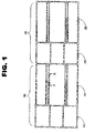
- FIG.1 shows an illustration of the framework of one embodiment of a reusable apparatus for shipping seating units, in accordance with the current invention.
- the framework comprises a first seat holding member 10 , including a first base portion 11 and a first back portion 12, and a second seat holding member 20 , including a second base portion 21 , and a second back portion 22 .
- Base portions 11 and 21 are the portions of the framework to which the bases of the seating units are affixed.
- the bases of the seating units may be pedestals, legs, or any appropriate base for a seating unit.
- Back portions 12 and 22 are those portions of the apparatus that support and protect the backs of the seating units.
- Back portions 12 and 22 are slidably adjustable to allow for different heights of seating units and to permit the apparatus to be collapsed into a smaller configuration than would be possible if the back portions were entirely fixed.
- First seat holding portion 10 is rotatably attached to second seat holding portion 20.
- Base portions 11 and 21 may also be rotatably attached to their respective back portions 12 and 22 .
- base portion 11 may be substantially perpendicular to back portion 12
- base portion 21 may be substantially perpendicular to back portion 22 .
- this configuration would not permit the apparatus to be fully extended as shown in Fig. 1 , nor could it be fully collapsed for storage or return to the shipper.
- the apparatus may be constructed using any strong, rigid material, for example a metal or a polycarbonate. To reduce the weight of the apparatus, a lightweight metal such as aluminum may be desirable.
- FIG. 2 is an illustration of seating units 30 in place on the apparatus shown in Fig. 1 .
- One seating unit is shown in place on base portion 11
- three seating units are shown in place on base portion 21 .
- the dimensions of the apparatus may be varied to accommodate any number of seating units, with the dimensions depending on the desired size and weight of the apparatus plus the seating units.
- a device 40 for releasably holding the seating units slidably receives at least a portion of the base of each seating unit.
- the dimensions of the device may be chosen to accommodate the appropriate number of seating units.
- a spring-loaded clip may also fit around a portion of the base of a seating unit.
- FIG. 3 is an illustration showing the apparatus of Figs. 1 and 2 partially rotated.
- Base portion 11 has been rotated such that the backs of the seating units attached to base portion 11 are now adjacent back portion 12 .
- Back portion 22 has been rotated such that it is adjacent the backs of the seating units attached to base portion 21 .
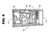
- FIG. 4 is an illustration showing the apparatus of Figs. 1-3 fully rotated and in position for shipping.
- the seating units are now inverted with respect to each other, and base portion 11 is now adjacent back portion 22 .
- a locking device known in the art may be used to releasably lock base portion 11 to back portion 22 .
- One or more lift-assist devices may be operably attached to the apparatus to aid in any or all of the rotations.
- a lift-assist device for example a hydraulic cylinder
- seating units may be rotated and prepared for shipment by a single worker or may even be automatically rotated when initiated by a worker.
- one or more support members 50 may be attached to the apparatus to releasably connect back portions 12 and 22 .
- Such support members may be made of the same material used to construct the apparatus framework, or they may be panels constructed of, for example, polycarbonate. Multiple support members may be used to ensure that the apparatus is adequately stable and rigid.
- a panel may be attached to each base portion and back portion, either before or after assembly of the apparatus.
- the panels may comprise a material such as polycarbonate that can withstand the rigors of shipment and will provide protection for the enclosed seating units. Transparent or translucent panels would permit the number of enclosed seating units to be viewed.
- a covering made of canvas or plastic, for example, may be placed over the apparatus to further protect the seating units from being damaged or soiled during shipping.
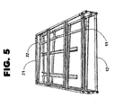
- FIG. 5 is an illustration showing the apparatus of Figs. 1-4 fully collapsed and in position for storage or return to the shipper.
- Back portions 12 and 22 have been slidably adjusted to their smallest dimensions, and the back and base portions have been rotated such that they are all adjacent one another.
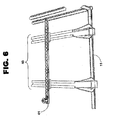
- FIG. 6 is a fragmentary view showing a device 40 for slidably receiving and releasably holding one or more seating units to the apparatus of Figs. 1-5 .
- a locking device 41 may be added to prevent the seating units from sliding back out of the holding device.
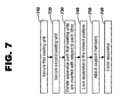
- FIG. 7 at 700 shows a flow diagram of one embodiment of a method of preparing seating units for shipment using an example apparatus according to Figs 1-6 .
- Method 700 comprises steps to secure a first seating unit in an upright position to an apparatus for shipping seating units, secure a second seating unit in an upright position to the apparatus, rotate at least a portion of the apparatus to a position such that the seating units are inverted with respect to each other, lock the apparatus in the rotated position, attach support members to the apparatus, and cover the apparatus.
- the user may secure a first seating unit in an upright position to the apparatus for shipping seating units (Block 710 ). This may be accomplished by, for example, sliding the runners of an airplane seat into a holding device affixed to a first base portion of the apparatus. The device may then be locked to ensure the runners remain in place and the seat remains stationary during shipment.
- the second seating unit may be secured in the same manner to a second base portion (Block 720 ).
- the user may then rotate the apparatus such that the seating units are inverted with respect to each other (Block 730 ). This may be accomplished by rotating the first base portion and the attached first seating unit until the seat is in a prone position, with the back of the first seating unit resting on a first back portion of the apparatus. The first base portion, the attached first seating unit, and the first back portion may then be rotated such that the first seating unit is in an inverted position with respect to the second seating unit. The second back portion may then be rotated such that it is adjacent the first base portion.
- One or more lift-assist devices may assert a lift-assist force to the apparatus to facilitate any or all of the rotations.
- the apparatus may be locked in the rotated position using a locking device by locking the first base portion to the second back portion (Block 740 ).
- Support members may be attached that connect the first back portion with the second back portion (Block 750 ).
- the support members may be tubular members such as those seen in Fig. 4 , or they may be panels constructed of, for example, polycarbonate. Multiple support members may be used to ensure that the apparatus is adequately stable and rigid.
- a covering made of canvas or plastic, for example, may be placed over the apparatus to further protect the seating units from being damaged or soiled during shipping (Block 760 ).
- the seating units may be unpacked after shipping and receipt by following the above steps in reverse order.
- the apparatus may then be collapsed as seen in Fig. 5 for storage or for shipment back to the supplier for use in future shipments.
Landscapes
- Engineering & Computer Science (AREA)
- Mechanical Engineering (AREA)
- Packaging Of Machine Parts And Wound Products (AREA)
- Rigid Containers With Two Or More Constituent Elements (AREA)
- Pallets (AREA)
Abstract
Description
- This invention relates generally to shipping containers. More specifically, the invention relates to an apparatus that is designed to be a reusable container for shipping seating units.
- Various containers are currently available for shipping and storing chairs and seats for vehicles such as automobiles, buses, and airplanes. These containers are designed to hold either a single seating unit or multiple units. Typically, multiple seating units are arranged with one unit upright and the other unit inverted. The two seating units are nested facing each other, with the top (or seat back) of each unit adjacent the base of the other unit.
- An L-shaped shipping container for a single chair or other article of furniture is disclosed in U.S. Pat. No. 4,871,061. A shipping container designed to accommodate a pair of chairs arranged in the nested configuration described above is disclosed in U.S. Pat. No. 4,170,297. These patents note a number of disadvantages of the prior art, including the amount of time and manual labor involved in assembling and sealing containers for shipment and in unpacking and disassembling the containers after receipt, the amount of excess paperboard used in forming and reinforcing containers, the failure of containers to adequately protect the contents, and the amount of excess space taken up by containers. An additional disadvantage that is not mentioned in or solved by these patents is the time and costs involved in disposing of the used container materials, either as garbage or by recycling.
- It would be desirable, therefore, to provide a reusable container for shipping seating units that overcomes the aforementioned and other disadvantages.
- One aspect of the invention provides a reusable apparatus for shipping seating units. The apparatus comprises first and second seat holding members. The first seat holding member includes a first base portion and a first back portion. The second seat holding member includes a second base portion and a second back portion. The first back portion is rotatably attached to the second base portion. A first seating unit secured to the first base portion and a second seating unit secured to the second base portion may be rotated such that the seating units are inverted with respect to each other and the first base portion of the apparatus is adjacent the second back portion of the apparatus.
- Another aspect of the invention provides a method of preparing seating units for shipment. The method comprises securing a first seating unit in an upright position to an apparatus for shipping seating units, securing a second seating unit in an upright position to the apparatus, and rotating at least a portion of the apparatus to a position such that the seating units are inverted with respect to each other.
- A further aspect of the invention provides a system for preparing seating units for shipment, comprising means for securing a first seating unit in an upright position to an apparatus for shipping seating units, means for securing a second seating unit in an upright position to the apparatus, and means for rotating at least a portion of the apparatus to a position such that the seating units are inverted with respect to each other.
- The aforementioned, and other features and advantages of the invention, will become further apparent from the following detailed description of the presently preferred embodiments, read in conjunction with the accompanying drawings. The detailed description and drawings are merely illustrative of the invention rather than limiting, the scope of the invention being defined by the appended claims and equivalents thereof.
-
- FIG. 1 is an illustration of the framework of one embodiment of a reusable apparatus for shipping seating units, in accordance with the current invention;
- FIG. 2 is an illustration of seating units in place on the apparatus shown in Fig. 1;
- FIG. 3 is an illustration showing the apparatus of Figs. 1 and 2 partially rotated;
- FIG. 4 is an illustration showing the apparatus of Figs. 1-3 fully rotated and in position for shipping;
- FIG. 5 is an illustration showing the apparatus of Figs. 1-4 fully collapsed and in position for storage or return to the shipper;
- FIG. 6 is a fragmentary view of one embodiment of a device for releasably holding a seating unit to the apparatus of Figs. 1-5; and
- FIG. 7 is a flow diagram of one embodiment of a method of preparing seating units for shipment using an example apparatus in accordance with the current invention.
-
- FIG.1 shows an illustration of the framework of one embodiment of a reusable apparatus for shipping seating units, in accordance with the current invention. The framework comprises a first
seat holding member 10, including afirst base portion 11 and afirst back portion 12, and a secondseat holding member 20, including asecond base portion 21, and asecond back portion 22. -
Base portions - Back
portions Back portions - First
seat holding portion 10 is rotatably attached to secondseat holding portion 20.Base portions respective back portions base portion 11 may be substantially perpendicular toback portion 12, andbase portion 21 may be substantially perpendicular toback portion 22. However, this configuration would not permit the apparatus to be fully extended as shown in Fig. 1, nor could it be fully collapsed for storage or return to the shipper. - The apparatus may be constructed using any strong, rigid material, for example a metal or a polycarbonate. To reduce the weight of the apparatus, a lightweight metal such as aluminum may be desirable.
- FIG. 2 is an illustration of
seating units 30 in place on the apparatus shown in Fig. 1. One seating unit is shown in place onbase portion 11, and three seating units are shown in place onbase portion 21. However, those skilled in the art will recognize that the dimensions of the apparatus may be varied to accommodate any number of seating units, with the dimensions depending on the desired size and weight of the apparatus plus the seating units. - In this embodiment, a
device 40 for releasably holding the seating units slidably receives at least a portion of the base of each seating unit. The dimensions of the device may be chosen to accommodate the appropriate number of seating units. Those skilled in the art will appreciate that many possible means for releasably holding the seating units are possible. For example, a spring-loaded clip may also fit around a portion of the base of a seating unit. - FIG. 3 is an illustration showing the apparatus of Figs. 1 and 2 partially rotated.
Base portion 11 has been rotated such that the backs of the seating units attached tobase portion 11 are nowadjacent back portion 12.Back portion 22 has been rotated such that it is adjacent the backs of the seating units attached tobase portion 21. - FIG. 4 is an illustration showing the apparatus of Figs. 1-3 fully rotated and in position for shipping. The seating units are now inverted with respect to each other, and
base portion 11 is nowadjacent back portion 22. A locking device known in the art may be used to releasably lockbase portion 11 toback portion 22. - One or more lift-assist devices may be operably attached to the apparatus to aid in any or all of the rotations. With the addition of a lift-assist device, for example a hydraulic cylinder, seating units may be rotated and prepared for shipment by a single worker or may even be automatically rotated when initiated by a worker.
- Once the apparatus has been fully rotated and in position for shipping, one or
more support members 50 may be attached to the apparatus to releasably connect backportions - A panel may be attached to each base portion and back portion, either before or after assembly of the apparatus. The panels may comprise a material such as polycarbonate that can withstand the rigors of shipment and will provide protection for the enclosed seating units. Transparent or translucent panels would permit the number of enclosed seating units to be viewed.
- A covering made of canvas or plastic, for example, may be placed over the apparatus to further protect the seating units from being damaged or soiled during shipping.
- FIG. 5 is an illustration showing the apparatus of Figs. 1-4 fully collapsed and in position for storage or return to the shipper. Back
portions - FIG. 6 is a fragmentary view showing a
device 40 for slidably receiving and releasably holding one or more seating units to the apparatus of Figs. 1-5. Those skilled in the art will appreciate that many possible means for releasably holding the seating units are possible. A lockingdevice 41 may be added to prevent the seating units from sliding back out of the holding device. - FIG. 7 at 700 shows a flow diagram of one embodiment of a method of preparing seating units for shipment using an example apparatus according to Figs 1-6. Method 700 comprises steps to secure a first seating unit in an upright position to an apparatus for shipping seating units, secure a second seating unit in an upright position to the apparatus, rotate at least a portion of the apparatus to a position such that the seating units are inverted with respect to each other, lock the apparatus in the rotated position, attach support members to the apparatus, and cover the apparatus.
- The user may secure a first seating unit in an upright position to the apparatus for shipping seating units (Block 710). This may be accomplished by, for example, sliding the runners of an airplane seat into a holding device affixed to a first base portion of the apparatus. The device may then be locked to ensure the runners remain in place and the seat remains stationary during shipment. The second seating unit may be secured in the same manner to a second base portion (Block 720).
- The user may then rotate the apparatus such that the seating units are inverted with respect to each other (Block 730). This may be accomplished by rotating the first base portion and the attached first seating unit until the seat is in a prone position, with the back of the first seating unit resting on a first back portion of the apparatus. The first base portion, the attached first seating unit, and the first back portion may then be rotated such that the first seating unit is in an inverted position with respect to the second seating unit. The second back portion may then be rotated such that it is adjacent the first base portion. One or more lift-assist devices may assert a lift-assist force to the apparatus to facilitate any or all of the rotations.
- The apparatus may be locked in the rotated position using a locking device by locking the first base portion to the second back portion (Block 740). Support members may be attached that connect the first back portion with the second back portion (Block 750). The support members may be tubular members such as those seen in Fig. 4, or they may be panels constructed of, for example, polycarbonate. Multiple support members may be used to ensure that the apparatus is adequately stable and rigid. A covering made of canvas or plastic, for example, may be placed over the apparatus to further protect the seating units from being damaged or soiled during shipping (Block 760).
- The seating units may be unpacked after shipping and receipt by following the above steps in reverse order. The apparatus may then be collapsed as seen in Fig. 5 for storage or for shipment back to the supplier for use in future shipments.
- While the embodiments of the invention disclosed herein are presently considered to be preferred, various changes and modifications can be made without departing from the spirit and scope of the invention. The scope of the invention is indicated in the appended claims, and all changes and modifications that come within the meaning and range of equivalents are intended to be embraced therein.
Claims (16)
- A system for preparing seating units for shipment, comprising:means for securing a first seating unit in an upright position to an apparatus for shipping seating units;means for securing a second seating unit in an upright position to the apparatus; andmeans for rotating at least a portion of the apparatus to a position such that the seating units are inverted with respect to each other.
- A reusable apparatus or system according to claim 1 for shipping seating units, comprising:a first seat holding member including a first base portion and a first back portion; anda second seat holding member including a second base portion and a second back portion, the first back portion rotatably attached to the second base portion, wherein a first seating unit secured to the first base portion and a second seating unit secured to the second base portion may be rotated such that the seating units are inverted with respect to each other and the first base portion is adjacent the second back portion
- The apparatus of claim 1 or 2 further comprising:a device for releasably locking the first base portion to the second back portion.
- The apparatus of claim 1, 2 or 3 further comprising:at least one lift assist device operably attached to the first back portion and the second base portion.
- The apparatus according to any of claims 1-4 further comprising:at least one support member, wherein the at least one support member releasably connects the first back portion with the second back portion.
- The apparatus according to any of claims 1-5 further comprising:a panel attached to each base portion and each back portion.
- The apparatus according to any of claims 1-6 wherein the panel comprises a material selected from a group consisting of polycarbonate, Poly(methyl methacrylate), a polymer.
- The apparatus according to any of claims 1-7 further comprising:a removable covering means that encloses at least a portion of the apparatus.
- The apparatus according to any of claims 1-8 wherein the back portions and the base portions are rotatably attached.
- The apparatus according to any of claims 1-9 wherein the first base portion is substantially perpendicular to the first back portion and the second base portion is substantially perpendicular to the second back portion.
- The apparatus according to any of claims 1-10 wherein at least one dimension of at least one back portion is slidably adjustable.
- The apparatus according to any of claims 1-11 wherein each base portion includes a device for releasably holding a seating unit.
- The apparatus of claim 12 wherein the device for releasably holding a seating unit slidably receives at least a portion of the base of the seating unit.
- The apparatus of claim 12 wherein the device for releasably holding a seating unit includes a locking device.
- A method of preparing seating units for shipment, comprising:securing a first seating unit to an apparatus for shipping seating units;securing a second seating unit to the apparatus; androtating at least a portion of the apparatus to a position such that the seating units are inverted with respect to each other.
- The method of claim 15 wherein an apparatus or system according to any of claims 1-15 is used.
Applications Claiming Priority (2)
| Application Number | Priority Date | Filing Date | Title |
|---|---|---|---|
| US405855 | 2003-04-02 | ||
| US10/405,855 US7025204B2 (en) | 2003-04-02 | 2003-04-02 | Reusable apparatus for shipping seating units |
Publications (2)
| Publication Number | Publication Date |
|---|---|
| EP1464590A1 true EP1464590A1 (en) | 2004-10-06 |
| EP1464590B1 EP1464590B1 (en) | 2006-07-12 |
Family
ID=32850627
Family Applications (1)
| Application Number | Title | Priority Date | Filing Date |
|---|---|---|---|
| EP20040075887 Revoked EP1464590B1 (en) | 2003-04-02 | 2004-03-18 | Reusable apparatus for shipping seating units |
Country Status (3)
| Country | Link |
|---|---|
| US (1) | US7025204B2 (en) |
| EP (1) | EP1464590B1 (en) |
| JP (1) | JP4416116B2 (en) |
Cited By (4)
| Publication number | Priority date | Publication date | Assignee | Title |
|---|---|---|---|---|
| EP1832528A1 (en) * | 2006-03-07 | 2007-09-12 | Faurecia Autositze GmbH | Stackable transport frame for picking and delivery of the complete seating of a motor vehicle |
| DE102009054037A1 (en) | 2008-11-18 | 2010-06-10 | Keiper Gmbh & Co. Kg | Transport frame-seat arrangement for commercial vehicle, has attachment device including clamping arrangement with clamp, and seat-cross brace guided into clamp and released from clamp by actuating vehicle seat adjuster at seat |
| WO2015023519A1 (en) * | 2013-08-12 | 2015-02-19 | Zodiac Seats Us Llc | Multiple seat shipping container |
| CN105539992A (en) * | 2016-01-22 | 2016-05-04 | 上海卢潘涵五金模具有限公司 | Automobile seat shipment line pallet |
Citations (3)
| Publication number | Priority date | Publication date | Assignee | Title |
|---|---|---|---|---|
| US3338501A (en) * | 1966-03-02 | 1967-08-29 | Container Corp | Container with adjustable inner packing |
| DE29607874U1 (en) * | 1996-04-30 | 1996-07-18 | Bertrand Faure Sitztechnik GmbH & Co. KG, 31655 Stadthagen | Transport rack |
| US20020100396A1 (en) * | 2001-01-26 | 2002-08-01 | Arthur Richard | Storage and transport support for airplane seat |
Family Cites Families (10)
| Publication number | Priority date | Publication date | Assignee | Title |
|---|---|---|---|---|
| US2331753A (en) * | 1940-06-01 | 1943-10-12 | Hinde & Dauch Paper Co | Furniture packing |
| US3651934A (en) * | 1969-07-16 | 1972-03-28 | Container Corp | Structure for nestably packing chairs for shipment |
| US3729893A (en) * | 1971-06-25 | 1973-05-01 | Armstrong Cork Co | Chair pack |
| US4111301A (en) * | 1976-12-17 | 1978-09-05 | Weyerhaeuser Company | One-piece chair shipping container |
| US4185741A (en) * | 1978-02-21 | 1980-01-29 | Packaging Corporation Of America | Shipping container and blank therefor |
| US4170297A (en) * | 1978-06-30 | 1979-10-09 | Packaging Corporation Of America | Shipping unit |
| US4574998A (en) * | 1984-08-01 | 1986-03-11 | Kohler Co. | Open-ended carton and carton blank |
| US4705162A (en) * | 1986-11-13 | 1987-11-10 | Kupersmit Julius B | Multiple display carton shipping package |
| US4871061A (en) * | 1988-08-10 | 1989-10-03 | Kimball International, Inc. | Furniture container |
| US6523692B2 (en) * | 1998-10-13 | 2003-02-25 | Fort James Corporation | Fold-in-half shipping/display box |
-
2003
- 2003-04-02 US US10/405,855 patent/US7025204B2/en not_active Expired - Fee Related
-
2004
- 2004-03-18 EP EP20040075887 patent/EP1464590B1/en not_active Revoked
- 2004-03-30 JP JP2004099345A patent/JP4416116B2/en not_active Expired - Lifetime
Patent Citations (3)
| Publication number | Priority date | Publication date | Assignee | Title |
|---|---|---|---|---|
| US3338501A (en) * | 1966-03-02 | 1967-08-29 | Container Corp | Container with adjustable inner packing |
| DE29607874U1 (en) * | 1996-04-30 | 1996-07-18 | Bertrand Faure Sitztechnik GmbH & Co. KG, 31655 Stadthagen | Transport rack |
| US20020100396A1 (en) * | 2001-01-26 | 2002-08-01 | Arthur Richard | Storage and transport support for airplane seat |
Cited By (9)
| Publication number | Priority date | Publication date | Assignee | Title |
|---|---|---|---|---|
| EP1832528A1 (en) * | 2006-03-07 | 2007-09-12 | Faurecia Autositze GmbH | Stackable transport frame for picking and delivery of the complete seating of a motor vehicle |
| DE102009054037A1 (en) | 2008-11-18 | 2010-06-10 | Keiper Gmbh & Co. Kg | Transport frame-seat arrangement for commercial vehicle, has attachment device including clamping arrangement with clamp, and seat-cross brace guided into clamp and released from clamp by actuating vehicle seat adjuster at seat |
| DE102009054037B4 (en) * | 2008-11-18 | 2011-02-03 | Keiper Gmbh & Co. Kg | Caddy vehicle seat assembly |
| WO2015023519A1 (en) * | 2013-08-12 | 2015-02-19 | Zodiac Seats Us Llc | Multiple seat shipping container |
| CN105358443A (en) * | 2013-08-12 | 2016-02-24 | 祖迪雅克座椅美国有限责任公司 | Multiple seat shipping container |
| US9815615B2 (en) | 2013-08-12 | 2017-11-14 | Zodiac Seats Us Llc | Multiple seat shipping container |
| CN105358443B (en) * | 2013-08-12 | 2018-06-01 | 祖迪雅克座椅美国有限责任公司 | multi seat shipping container |
| CN105539992A (en) * | 2016-01-22 | 2016-05-04 | 上海卢潘涵五金模具有限公司 | Automobile seat shipment line pallet |
| CN105539992B (en) * | 2016-01-22 | 2017-10-20 | 延锋安道拓座椅有限公司 | A kind of automotive seat ships line pallet |
Also Published As
| Publication number | Publication date |
|---|---|
| US7025204B2 (en) | 2006-04-11 |
| EP1464590B1 (en) | 2006-07-12 |
| JP4416116B2 (en) | 2010-02-17 |
| JP2004307068A (en) | 2004-11-04 |
| US20040195126A1 (en) | 2004-10-07 |
Similar Documents
| Publication | Publication Date | Title |
|---|---|---|
| US5421637A (en) | Foldable stadium seat and storage apparatus | |
| US20130075214A1 (en) | Novel folding luggage and duffles and hinges therefor | |
| US9247818B2 (en) | Portable folding chair with removable storage module | |
| US8528931B2 (en) | Device for transporting shopping | |
| US20090152825A1 (en) | Bag retainer/transporter and method of use thereof | |
| US10206496B1 (en) | Integrated foldable table and bench assembly | |
| CN102713111B (en) | Collapsible shade device | |
| US10405621B2 (en) | Collapsible, lightweight container for sorting and delivery of packaged items | |
| US9908694B2 (en) | Lightweight commercial dumpster | |
| US20030075476A1 (en) | Storage and transport system for collapsible tradeshow displays | |
| EP1464590B1 (en) | Reusable apparatus for shipping seating units | |
| US5529375A (en) | Beach chair love seat | |
| EP2089276A2 (en) | Folding cart for galley | |
| EP3033277B1 (en) | Multiple seat shipping container | |
| EP2930105A1 (en) | Foldaway cart for wheelchair stowage aboard a commercial aircraft | |
| US10206495B2 (en) | Vehicle receiver hitch-supported cargo rack transformable into a picnic table with benches | |
| US8261924B2 (en) | Folding containers | |
| US9126538B1 (en) | Vehicle including collapsible cargo container | |
| US7669718B1 (en) | Convertible display fixture | |
| US20040056059A1 (en) | Cargo shelf | |
| US20140197050A1 (en) | Travel Container for Transporting Of Beverage Containers | |
| US6036012A (en) | Wheelchair container | |
| US20060267393A1 (en) | Utility bench | |
| GB2498404A (en) | Collapsible trolley for transferring heavy loads across rough terrain | |
| JP2018019734A (en) | Multipurpose carrying case |
Legal Events
| Date | Code | Title | Description |
|---|---|---|---|
| PUAI | Public reference made under article 153(3) epc to a published international application that has entered the european phase |
Free format text: ORIGINAL CODE: 0009012 |
|
| AK | Designated contracting states |
Kind code of ref document: A1 Designated state(s): AT BE BG CH CY CZ DE DK EE ES FI FR GB GR HU IE IT LI LU MC NL PL PT RO SE SI SK TR |
|
| AX | Request for extension of the european patent |
Extension state: AL LT LV MK |
|
| 17P | Request for examination filed |
Effective date: 20050405 |
|
| AKX | Designation fees paid |
Designated state(s): FR GB IE IT |
|
| REG | Reference to a national code |
Ref country code: DE Ref legal event code: 8566 |
|
| GRAP | Despatch of communication of intention to grant a patent |
Free format text: ORIGINAL CODE: EPIDOSNIGR1 |
|
| GRAS | Grant fee paid |
Free format text: ORIGINAL CODE: EPIDOSNIGR3 |
|
| GRAA | (expected) grant |
Free format text: ORIGINAL CODE: 0009210 |
|
| AK | Designated contracting states |
Kind code of ref document: B1 Designated state(s): FR GB IE IT |
|
| PG25 | Lapsed in a contracting state [announced via postgrant information from national office to epo] |
Ref country code: IT Free format text: LAPSE BECAUSE OF FAILURE TO SUBMIT A TRANSLATION OF THE DESCRIPTION OR TO PAY THE FEE WITHIN THE PRESCRIBED TIME-LIMIT;WARNING: LAPSES OF ITALIAN PATENTS WITH EFFECTIVE DATE BEFORE 2007 MAY HAVE OCCURRED AT ANY TIME BEFORE 2007. THE CORRECT EFFECTIVE DATE MAY BE DIFFERENT FROM THE ONE RECORDED. Effective date: 20060712 |
|
| REG | Reference to a national code |
Ref country code: GB Ref legal event code: FG4D |
|
| REG | Reference to a national code |
Ref country code: IE Ref legal event code: FG4D |
|
| RAP2 | Party data changed (patent owner data changed or rights of a patent transferred) |
Owner name: THE BOEING COMPANY |
|
| ET | Fr: translation filed | ||
| PGFP | Annual fee paid to national office [announced via postgrant information from national office to epo] |
Ref country code: IE Payment date: 20070327 Year of fee payment: 4 |
|
| PLBI | Opposition filed |
Free format text: ORIGINAL CODE: 0009260 |
|
| 26 | Opposition filed |
Opponent name: AIRBUS DEUTSCHLAND GMBH/AIRBUS FRANCE SAS/AIRBUS U Effective date: 20070402 |
|
| PLAX | Notice of opposition and request to file observation + time limit sent |
Free format text: ORIGINAL CODE: EPIDOSNOBS2 |
|
| PLBB | Reply of patent proprietor to notice(s) of opposition received |
Free format text: ORIGINAL CODE: EPIDOSNOBS3 |
|
| RDAF | Communication despatched that patent is revoked |
Free format text: ORIGINAL CODE: EPIDOSNREV1 |
|
| RDAG | Patent revoked |
Free format text: ORIGINAL CODE: 0009271 |
|
| STAA | Information on the status of an ep patent application or granted ep patent |
Free format text: STATUS: PATENT REVOKED |
|
| PGFP | Annual fee paid to national office [announced via postgrant information from national office to epo] |
Ref country code: GB Payment date: 20080327 Year of fee payment: 5 |
|
| 27W | Patent revoked |
Effective date: 20080217 |
|
| GBPR | Gb: patent revoked under art. 102 of the ep convention designating the uk as contracting state |
Effective date: 20080217 |
|
| PGFP | Annual fee paid to national office [announced via postgrant information from national office to epo] |
Ref country code: FR Payment date: 20080317 Year of fee payment: 5 |
|
| PGFP | Annual fee paid to national office [announced via postgrant information from national office to epo] |
Ref country code: IT Payment date: 20090327 Year of fee payment: 6 |