EP1464495A2 - Fluid ejection device - Google Patents
Fluid ejection device Download PDFInfo
- Publication number
- EP1464495A2 EP1464495A2 EP03022937A EP03022937A EP1464495A2 EP 1464495 A2 EP1464495 A2 EP 1464495A2 EP 03022937 A EP03022937 A EP 03022937A EP 03022937 A EP03022937 A EP 03022937A EP 1464495 A2 EP1464495 A2 EP 1464495A2
- Authority
- EP
- European Patent Office
- Prior art keywords
- drop weight
- fluid
- firing chamber
- heating element
- present
- Prior art date
- Legal status (The legal status is an assumption and is not a legal conclusion. Google has not performed a legal analysis and makes no representation as to the accuracy of the status listed.)
- Granted
Links
Images




Classifications
-
- B—PERFORMING OPERATIONS; TRANSPORTING
- B41—PRINTING; LINING MACHINES; TYPEWRITERS; STAMPS
- B41J—TYPEWRITERS; SELECTIVE PRINTING MECHANISMS, i.e. MECHANISMS PRINTING OTHERWISE THAN FROM A FORME; CORRECTION OF TYPOGRAPHICAL ERRORS
- B41J2/00—Typewriters or selective printing mechanisms characterised by the printing or marking process for which they are designed
- B41J2/005—Typewriters or selective printing mechanisms characterised by the printing or marking process for which they are designed characterised by bringing liquid or particles selectively into contact with a printing material
- B41J2/01—Ink jet
- B41J2/015—Ink jet characterised by the jet generation process
- B41J2/04—Ink jet characterised by the jet generation process generating single droplets or particles on demand
- B41J2/045—Ink jet characterised by the jet generation process generating single droplets or particles on demand by pressure, e.g. electromechanical transducers
- B41J2/04501—Control methods or devices therefor, e.g. driver circuits, control circuits
- B41J2/04551—Control methods or devices therefor, e.g. driver circuits, control circuits using several operating modes
-
- B—PERFORMING OPERATIONS; TRANSPORTING
- B41—PRINTING; LINING MACHINES; TYPEWRITERS; STAMPS
- B41J—TYPEWRITERS; SELECTIVE PRINTING MECHANISMS, i.e. MECHANISMS PRINTING OTHERWISE THAN FROM A FORME; CORRECTION OF TYPOGRAPHICAL ERRORS
- B41J2/00—Typewriters or selective printing mechanisms characterised by the printing or marking process for which they are designed
- B41J2/005—Typewriters or selective printing mechanisms characterised by the printing or marking process for which they are designed characterised by bringing liquid or particles selectively into contact with a printing material
- B41J2/01—Ink jet
- B41J2/015—Ink jet characterised by the jet generation process
- B41J2/04—Ink jet characterised by the jet generation process generating single droplets or particles on demand
- B41J2/045—Ink jet characterised by the jet generation process generating single droplets or particles on demand by pressure, e.g. electromechanical transducers
- B41J2/04501—Control methods or devices therefor, e.g. driver circuits, control circuits
- B41J2/0458—Control methods or devices therefor, e.g. driver circuits, control circuits controlling heads based on heating elements forming bubbles
-
- B—PERFORMING OPERATIONS; TRANSPORTING
- B41—PRINTING; LINING MACHINES; TYPEWRITERS; STAMPS
- B41J—TYPEWRITERS; SELECTIVE PRINTING MECHANISMS, i.e. MECHANISMS PRINTING OTHERWISE THAN FROM A FORME; CORRECTION OF TYPOGRAPHICAL ERRORS
- B41J2/00—Typewriters or selective printing mechanisms characterised by the printing or marking process for which they are designed
- B41J2/005—Typewriters or selective printing mechanisms characterised by the printing or marking process for which they are designed characterised by bringing liquid or particles selectively into contact with a printing material
- B41J2/01—Ink jet
- B41J2/015—Ink jet characterised by the jet generation process
- B41J2/04—Ink jet characterised by the jet generation process generating single droplets or particles on demand
- B41J2/045—Ink jet characterised by the jet generation process generating single droplets or particles on demand by pressure, e.g. electromechanical transducers
- B41J2/04501—Control methods or devices therefor, e.g. driver circuits, control circuits
- B41J2/04593—Dot-size modulation by changing the size of the drop
-
- B—PERFORMING OPERATIONS; TRANSPORTING
- B41—PRINTING; LINING MACHINES; TYPEWRITERS; STAMPS
- B41J—TYPEWRITERS; SELECTIVE PRINTING MECHANISMS, i.e. MECHANISMS PRINTING OTHERWISE THAN FROM A FORME; CORRECTION OF TYPOGRAPHICAL ERRORS
- B41J2/00—Typewriters or selective printing mechanisms characterised by the printing or marking process for which they are designed
- B41J2/005—Typewriters or selective printing mechanisms characterised by the printing or marking process for which they are designed characterised by bringing liquid or particles selectively into contact with a printing material
- B41J2/01—Ink jet
- B41J2/135—Nozzles
- B41J2/14—Structure thereof only for on-demand ink jet heads
- B41J2/14016—Structure of bubble jet print heads
-
- B—PERFORMING OPERATIONS; TRANSPORTING
- B41—PRINTING; LINING MACHINES; TYPEWRITERS; STAMPS
- B41J—TYPEWRITERS; SELECTIVE PRINTING MECHANISMS, i.e. MECHANISMS PRINTING OTHERWISE THAN FROM A FORME; CORRECTION OF TYPOGRAPHICAL ERRORS
- B41J2/00—Typewriters or selective printing mechanisms characterised by the printing or marking process for which they are designed
- B41J2/005—Typewriters or selective printing mechanisms characterised by the printing or marking process for which they are designed characterised by bringing liquid or particles selectively into contact with a printing material
- B41J2/01—Ink jet
- B41J2/21—Ink jet for multi-colour printing
- B41J2/2121—Ink jet for multi-colour printing characterised by dot size, e.g. combinations of printed dots of different diameter
-
- B—PERFORMING OPERATIONS; TRANSPORTING
- B41—PRINTING; LINING MACHINES; TYPEWRITERS; STAMPS
- B41J—TYPEWRITERS; SELECTIVE PRINTING MECHANISMS, i.e. MECHANISMS PRINTING OTHERWISE THAN FROM A FORME; CORRECTION OF TYPOGRAPHICAL ERRORS
- B41J2202/00—Embodiments of or processes related to ink-jet or thermal heads
- B41J2202/01—Embodiments of or processes related to ink-jet heads
- B41J2202/06—Heads merging droplets coming from the same nozzle
Definitions
- the present claimed invention relates to fluid ejection devices. More specifically, the present claimed invention relates to generating multiple drops weights in a fluid ejection device.
- each print mode and/or print media may use a particular drop weight in order to maximize efficiency of the printing process. That is, when in draft mode, or when operating in high throughput printing conditions, it may be desirable to eject higher weight ink drops from the firing chamber of the printhead. Conversely, photo printing or UIQ (ultimate image quality) printing may be performed more effectively by ejecting lower weight ink drops from the firing chamber of the printhead.
- UIQ printing is thought to exist only when drop weights are on the order of 1-2 nanograms thereby reaching the visual perception limits of the human eye.
- Draft mode printing may typically operate efficiently with ink drop weights of at least 3-6 nanograms.
- a pen having a printhead designed for one type of printing mode or media is often not well suited for use with a separate and different type of printing mode or media.
- the printing mode may not be consistent throughout an entire print job. For example, on a single page it may be desirable to print a high quality image (e.g. a photographic image) on one portion of the page and print a lower quality image (e.g. a monochrome region) on another portion of the page.
- a low drop weight printhead may be used to achieve the photo quality resolution of the photographic image, but such a low drop weight printhead may not be particularly efficient for printing the monochrome region.
- a particular printhead which is chosen for its ability to perform photo quality printing may ultimately reduce the efficiency of an overall printing process.
- the present invention recites a fluid ejection device comprising a first drop ejector associated with a firing chamber.
- the first drop ejector is configured to cause fluid having a first drop weight to be ejected from the firing chamber, wherein the first drop ejector includes a first heating element and first drive circuitry electrically coupled with the first heating element.
- the present embodiment further comprises a first bore disposed within an orifice layer disposed proximate the first drop ejector and associated with the first drop ejector.
- the present embodiment also comprises a second drop ejector associated with the firing chamber.
- the second drop ejector is configured to cause fluid having a second drop weight to be ejected from the firing chamber, wherein the second drop ejector includes a second heating element and second drive circuitry electrically coupled with the second heating element.
- the present embodiment further comprises a second bore disposed within the orifice layer disposed proximate the second drop ejector, and the second bore is associated with the second drop ejector.
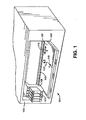
- FIG. 1 a perspective diagram (partial cut-away) of an exemplary printer system 101 in which a printhead including a multi-drop weight firing architecture may be employed in accordance with embodiments of the present invention is shown.
- Exemplary printer system 101 includes a printer housing 103 having platen 105 to which input media 107 (e.g. paper) is transported by mechanisms known in the art.
- exemplary printer system 101 includes a carriage 109 holding at least one replaceable printer component 111 (e.g. a printer cartridge) for ejecting fluid such as ink onto input media 107.
- Carriage 109 is typically mounted on a slide bar 113 or similar mechanism to allow the carriage 109 to be moved along a scan axis, X, denoted by arrow 115.
- input media 107 is moved along a feed axis, Y, denoted by arrow 119.
- input media 107 travels along the feed axis, Y, while ink is ejected along an ink drop trajectory axis, Z, as shown by arrow 117.
- Exemplary printer system 101 is also well suited to use with replaceable printer components such as semi-permanent printhead mechanisms having at least one small volume, on-board, ink chamber that is sporadically replenished from fluidically-coupled, off-axis, ink reservoirs or replaceable printer components having two or more colors of ink available within the replaceable printer components and ink ejecting nozzles specifically designated for each color.
- Exemplary printer system 101 is also well suited to use with replaceable printer components of various other types and structures. Although such an exemplary printer system 101 is shown in Figure 1, embodiments of the present invention, as will be described below in detail, are well suited to use with various other types of printer systems.
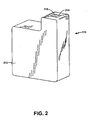
- Replaceable printer component 111 is comprised of a housing or shell 212 which contains an internal reservoir of ink (not shown).
- Replaceable printer component 111 further contains a printhead 214 with orifices (such as bores) 216 corresponding to firing chambers disposed thereunder.
- orifices such as bores
- ink is ejected from the firing chambers through orifices and is subsequently deposited onto print media 107.
- Figure 2 various embodiments of the present invention are well suited to use with numerous other types and/or styles of replaceable printer components.
- portion 302 includes a substrate 313 above which is formed a firing chamber 301.
- a plurality of heating elements 303 and 304 are schematically shown disposed within firing chamber 301.
- firing chamber 301 is defined partially by firing chamber walls 315.
- each of the plurality of heating elements 303 and 304 is coupled with respective, separately addressable, drive circuitry, not shown.
- portion 302 of the printhead of Figure 3 includes an opening 307 through which ink is supplied to firing chamber 301.
- an orifice layer 305 is disposed such that openings or bores 317 and 319 formed therethrough are located proximate heating elements 303 and 304, respectively.
- the term "drop ejector" refers to a combination of at least one heating element and at least one corresponding drive circuitry. Although such a definition for a drop ejector is used in accordance with one embodiment, the present invention is well suited to use with drop ejector comprised of various components other than a combination of at least one heating element and at least one corresponding drive circuitry.
- a single or common firing chamber may also have partial walls or other structures disposed between adjacent heating elements.
- the terms "common" or “single” firing chamber are defined as given below.
- a common firing chamber is defined as a firing chamber fed by a single fluid channel or single group of fluid channels.
- FIG. 4 a plan view is shown of a plurality of heating elements 303 and 304 located in a common firing chamber 301 and a plurality of drive circuitry 406 and 408 and bores 317 and 319 located proximate to common firing chamber 301 of a multi-drop weight firing architecture in accordance with various embodiments of the present claimed invention.
- Regions 402 and 404 are provided to illustrate possible electrical contact locations for accommodating current flow through heating elements 303 and 304, respectively.
- heating element 303 is electrically coupled with drive circuitry 406 and is further configured to cause fluid having a first drop weight to be ejected from firing chamber 301.
- heating element 303 is designed to have a particular surface area and is also designed to receive sufficient current from drive circuitry 406 to cause fluid having a desired drop weight to be ejected from firing chamber 301.
- the size of the drop weight generated by heating element 303 can be predetermined by selecting an appropriate heating element surface area and drive circuitry current combination. For example, in one embodiment, a larger drop weight is achieved by increasing the size of heating element 303 such that a larger volume of fluid is ultimately ejected from firing chamber 301.
- drive circuitry 406 increases the amount of current applied to heating element 303 such that a larger volume of fluid is ultimately ejected from firing chamber 301. In yet another embodiment, a larger drop weight of fluid is obtained by both increasing the size of heating element 303 and increasing the amount of current applied to heating element 303 by drive circuitry 406.
- the size of the drop weight generated by heating element 303 can also be substantially predetermined by selecting an appropriate bore size and/or shape. Specifically, in one embodiment, a larger bore size is used such that a larger volume of fluid is ultimately ejected from firing chamber 301. In another embodiment, the size of the bore or bores is reduced such that a smaller volume of fluid is ultimately ejected from firing chamber 301. It will further be understood that, in various embodiments of the present invention, the shape of the bores is adjusted to achieve a larger or smaller drop weight.
- a 5 nanogram drop weight is achieved by using heating element with a surface area of approximately 400 square micrometers, and by selecting a bore diameter of approximately 13 micrometers (bore area of approximately 133.5 square micrometers).
- a heating element with a surface area of approximately 250 square micrometers, and selects a bore diameter of approximately 8 micrometers (bore area of approximately 50.5 square micrometers).
- heating element 304 is electrically coupled with drive circuitry 408 and is further configured to cause fluid having a second drop weight to be ejected from firing chamber 301.
- heating element 304 is designed to have a particular surface area and is also designed to receive sufficient current from drive circuitry 408 to cause fluid having a desired drop weight to be ejected from firing chamber 301.
- the size of the drop weight generated by heating element 304 can also be predetermined by selecting an appropriate heating element surface area and drive circuitry current combination. For example, in one embodiment, a larger drop weight is achieved by increasing the size of heating element 304 such that a larger volume of fluid is ultimately ejected from firing chamber 301. Also, in another embodiment, drive circuitry 408 increases the amount of current applied to heating element 304 such that a larger volume of fluid is ultimately ejected from firing chamber 301. In yet another embodiment, a larger drop weight of fluid is obtained by both increasing the size of heating element 304 and increasing the amount of current applied to heating element 304 by drive circuitry 408.
- the size of the drop weight generated by heating element 304 can also be predetermined by selecting an appropriate bore size and/or shape. Specifically, in one embodiment, a larger bore size is used such that a larger volume of fluid is ultimately ejected from firing chamber 301. In another embodiment, the size of the bore or bores is reduced such that a smaller volume of fluid is ultimately ejected from firing chamber 301. It will further be understood that, in various embodiments of the present invention, the shape of the bores is adjusted to achieve a larger or smaller drop weight.
- a 5 nanogram drop weight is achieved by using heating element with a surface area of approximately 400 square micrometers, and by selecting a bore diameter of approximately 13 micrometers (bore area of approximately 133.5 square micrometers).
- a heating element with a surface area of approximately 250 square micrometers, and selects a bore diameter of approximately 8 micrometers (bore area of approximately 50.5 square micrometers).
- drive circuitry 406 and drive circuitry 408 are separately addressable. That is, each of drive circuitry 406 and drive circuitry 408 can be independently activated and controlled such that fluid having the first drop weight is ejectable from firing chamber 301 in one embodiment substantially concurrently or in a second embodiment separately from fluid having the second drop weight.
- each of drive circuitry 406 and drive circuitry 408 are comprised, for example, of a transistor coupled with addressing interconnections and the like for selectively providing current to heating elements 303 and 304, respectively.
- a drive circuitry structure is recited in the present embodiment, the present invention is not limited to such an embodiment, and, in fact, the present invention is well suited to use with various other types of drive circuitry for providing current to a respective heating element.
- heating element 303 is configured to cause fluid having a drop weight on the order of 1-2 nanograms to be ejected from firing chamber 301.
- the desired drop weight is achieved by altering the size of heating element 303 such that the desired volume of fluid is ultimately ejected from firing chamber 301.
- a 1-2 nanogram drop weight is used to achieve UIQ (ultimate image quality) resolution.
- heating element 303 when drive circuitry 406 is activated, heating element 303 will cause fluid having a drop weight meeting UIQ printing specifications to be ejected from firing chamber 301.
- heating element 304 is configured to cause fluid having a drop weight on the order of 3 nanograms to be ejected from firing chamber 301.
- the desired drop weight is achieved by selecting the size of heating element 304 such that the desired volume of fluid is ultimately ejected from firing chamber 301.
- draft mode printing for example, may typically operate efficiently with ink drop weights of at least 3-6 nanograms.
- heating element 304 when only drive circuitry 408 is activated, heating element 304 will cause fluid having a drop weight commensurate with drafting mode printing specifications to be ejected from firing chamber 301.
- heating elements 303 and 304 can be activated in one embodiment substantially concurrently or in a second embodiment separately.
- the present embodiment can further enhance the efficiency of printing, for example, in draft mode by substantially concurrently activating drive circuitry 406 and 408.
- heating element 303 will cause fluid having a drop weight on the order of 1-2 nanograms to be ejected from firing chamber 301 concurrent with heating element 304 causing fluid having a drop weight on the order of 3 nanograms to be ejected from firing chamber 301.
- a total drop weight of 4-5 nanograms will by produced by the present embodiment. This increased total drop weight enables greater media throughput speeds while maintaining print quality.
- the multi-drop weight firing architecture of the present embodiment is able to selectively generate, from a single firing chamber 301, a drop weight of 1-2 nanograms, a drop weight of 3 nanograms, or a drop weight of 4-5 nanograms.
- the plurality of drops of fluid ejected from firing chamber 301 merge prior to impacting the print media.
- the plurality of drops of fluid ejected from firing chamber merge after reaching the print media.
- both heating element 303 and heating element 304 can be configured to cause fluid having a drop weight on the order of 1-2 nanograms to be ejected from firing chamber 301.
- the plurality of independently activatable heating elements, 303 and 304, disposed in the common firing chamber can be used, for example, to provide redundancy or can be fired alternately to provide for increased fluid flux.
- the present embodiment specifically recites an embodiment in which two heating elements, disposed in a common firing chamber, each have a respective drive circuitry electrically coupled therewith.
- the present invention is, however, also well suited to an embodiment in which there are "x" heating elements (e.g. 6 heating elements), disposed in a common firing chamber, are electrically coupled with less than "x" respective sets of drive circuitry. That is, the present invention is well suited to an embodiment in which a plurality of heating elements (greater than two) are disposed in a common firing chamber, and a plurality of sets (not necessarily greater than two) of independently addressable drive circuitry are used to control the plurality of heating elements.
- the multi-drop weight firing architecture of the present invention is also well suited to dynamically selecting the cumulative drop weight ejected from firing chamber 301.
- Such an embodiment is particularly beneficial, for example, when the printing mode is not consistent throughout an entire print job.
- a high quality image e.g. a photographic image
- a lower quality image e.g. a monochrome region
- the present embodiment will activate heating element 304 using drive circuitry 408 and thereby cause fluid having a drop weight on the order of 3 nanograms to be ejected from firing chamber 301.
- the present embodiment will generate the higher drop weight to efficiently print the monochrome region.
- the present embodiment will dynamically cease firing of heating element 304, using drive circuitry 408, and instead activate only heating element 303, via drive circuitry 406, thereby causing fluid having a drop weight on the order of 1-2 nanograms to be ejected from firing chamber 301.
- the present embodiment will dynamically generate the low drop weight to achieve the resolution to properly print the photographic image.
- the present embodiment can dynamically re-activate heating element 304 using drive circuitry 408 to increase printing efficiency and throughput.
- the present invention is also well suited to dynamically activating both heating element 303 and heating element 304 to produce a cumulative drop weight of 4-5 nanograms to even further increase printing efficiency throughout.
- the present invention is not limited to the specific drop weight examples given above. That is, the present invention is well suited to generating various other drop sizes for one or both of heating elements 303 and 304.
- the present embodiment of the multi-drop weight firing architecture is able to accommodate multiple printing modes or media with, for example, a single printhead. Furthermore, the multi-drop weight firing architecture of the present embodiment is able to accommodate multiple printing modes or types using a single printhead and without ultimately reducing the efficiency of an overall printing process.
- the multi-drop weight firing architecture is compatible with existing firing chamber, printhead, and printer component fabrication processes. That is, the present multi-drop weight firing architecture can be manufactured using existing fabrication processes and equipment.
- bores 317 and 319 are formed proximate to and correspond with heating element 303 and heating element 304, respectively.
- bore 317 is disposed to direct the flow or trajectory of fluid which heating element 303 causes to be ejected from firing chamber 301.
- bore 319 is disposed to direct the flow or trajectory of fluid which heating element 304 causes to be ejected from firing chamber 301.
- bores 317 and 319 are disposed offset from heating element 303 and heating element 304, respectively. That is, the center of bore 317 is not centered with respect to heating element 303, and, similarly, the center of bore 319 is not centered with respect to heating element 304.
- the orientation and function of bores 317 and 319 are further described in conjunction with Figures 5A and 5B below.
- FIG. 5A a side sectional schematic view is shown of a plurality of heating elements 303 and 304 located in a common firing chamber, and corresponding offset bores 317 and 319, respectively, formed through, for example, an orifice layer 305.
- bores 317 and 319 are disposed offset from (i.e. not centered with respect to) heating element 303 and heating element 304, respectively.
- fluid which heating element 303 causes to be ejected from the common firing chamber is directed along an angled trajectory as schematically indicated by arrow 502.
- fluid which heating element 304 causes to be ejected from the common firing chamber is directed along an angled trajectory as schematically indicated by arrow 504.
- the present embodiment is able to direct or "aim" the ejected fluid in a desired direction.
- the ejected fluid is directed towards a common location such as, for example, a desired pixel location on a print medium.
- both of bores 317 and 319 are disposed in an offset orientation in the present embodiment, the present invention is also well suited to an embodiment in which only one or the other of bores 317 and 319 are centered over their corresponding heating element.
- the present invention is also well suited to an embodiment in which the trajectory of the ejected fluid is other than that shown in the embodiment of Figure 5A.
- offset bores are used in the present embodiment to achieve an angled trajectory for the ejected fluid
- the present invention is also well suited to using various approaches other than offset bores to achieve an angled trajectory for the ejected fluid.
- FIG. 5B a side sectional schematic view is shown of a plurality of heating elements 303 and 304 located in a common firing chamber, and corresponding aligned bores 317 and 319, respectively, formed through, for example, an orifice layer 305.
- bores 317 and 319 are disposed aligned with (i.e. centered with respect to) heating element 303 and heating element 304, respectively.
- fluid which heating element 303 causes to be ejected from the common firing chamber is directed along a trajectory as indicated by arrow 506.
- fluid which heating element 304 causes to be ejected from the common firing chamber is directed along a trajectory as indicated by arrow 508 which is substantially parallel to the trajectory indicated by arrow 506.
- arrow 508 which is substantially parallel to the trajectory indicated by arrow 506.
- FIG. 6 a plan view is shown, in accordance with one embodiment of the present claimed invention, of a plurality of heating elements 602, 604, and 606 located in a common firing chamber schematically denoted as 601.
- the present embodiment also includes a plurality of drive circuitry 608 and 610 and bores 612, 614, and 616 located proximate to common firing chamber 601.
- Region 618 is provided to illustrate a possible electrical contact location for accommodating current flow through heating elements 602 and 606.
- Region 620 is provided to illustrate a possible electrical contact location for accommodating current flow through heating element 604.
- heating element 604 is electrically coupled with drive circuitry 610 and is further configured to cause fluid having a first drop weight to be ejected from firing chamber 601.
- heating element 604 is designed to have a particular surface area and is also designed to receive sufficient current from drive circuitry 610 to cause fluid having a desired drop weight to be ejected from firing chamber 601. It will be understood that the size of the drop weight generated by heating element 604 can be predetermined by selecting an appropriate heating element surface area and drive circuitry current combination. Additionally or alternatively, it will further be understood that the size of the drop weight generated by heating element 604 can also be predetermined by selecting an appropriate bore size and/or shape. Specifically, in one embodiment, a larger bore size is used such that a larger volume of fluid is ultimately ejected from firing chamber 601. In another embodiment, the size of the bore or bores is reduced such that a smaller volume of fluid is ultimately ejected from firing chamber 601. It will further be understood that, in various embodiments of the present invention, the shape of the bores is adjusted to achieve a larger or smaller drop weight.
- drive circuitry 608 is electrically coupled with heating elements 602 and 606 which are configured to cause fluid having a second drop weight and a third drop weight, respectively, to be ejected from firing chamber 601.
- heating elements 602 and 606 are designed to have particular, respective, surface areas and are also designed to receive sufficient current from drive circuitry 608 to cause fluid having the desired second and third drop weights to be ejected from firing chamber 601. It will be understood that the size of the second and third drop weights generated by heating elements 602 and 606, respectively, can be predetermined by selecting an appropriate heating element surface area and drive circuitry current combination.
- the size of the drop weight generated by heating elements 602 and 606 can also be predetermined by selecting an appropriate bore size and/or shape. It will further be understood that the size of the drop weight generated by heating elements 602 and 606 can also be predetermined by selecting an appropriate bore size and/or shape. Specifically, in one embodiment, a larger bore size is used such that a larger volume of fluid is ultimately ejected from firing chamber 601. In another embodiment, the size of the bore or bores is reduced such that a smaller volume of fluid is ultimately ejected from firing chamber 601. It will further be understood that, in various embodiments of the present invention, the shape of the bores is adjusted to achieve a larger or smaller drop weight.
- a 5 nanogram drop weight is achieved by using heating element with a surface area of approximately 400 square micrometers, and by selecting a bore diameter of approximately 13 micrometers (bore area of approximately 133.5 square micrometers).
- a heating element with a surface area of approximately 250 square micrometers, and selects a bore diameter of approximately 8 micrometers (bore area of approximately 50.5 square micrometers).
- the present invention is well suited to various other configurations for the present multi-drop weight firing architecture.
- the present invention is also well suited to an embodiment which includes more than three heating elements within a common firing chamber.
- the present embodiment is also well suited to an embodiment in which a single heating element is configured to substantially concurrently cause the generation of more than two drops of fluid to be ejected from a firing chamber.
- the single heating element will include more than two regions which cause the ejection of fluid once drive circuitry applies current thereto.
- each of heating elements 602, 604, and 606 is coupled to separate independently addressable drive circuitry (i.e. where heating elements 602 and 606 do not share a common drive circuitry).
- the embodiment of the present multi-firing architecture is comprised of at least two heating elements coupled to a respective at least two drive circuits.
- the present embodiment provides a multi-drop weight firing architecture which can selectively eject up to three separate drops from common firing chamber 601. That is, the present embodiment can eject only fluid having a first drop weight as is generated by heating element 604. Alternatively, the present embodiment can eject fluid having a second drop weight and a third drop weight as is generated by heating element 602 and 606, respectively. The heating elements 602 and 606 eject the second and third drops weights substantially concurrently.
- the present embodiment can substantially concurrently eject fluid having the first drop weight, fluid having the second drop weight, and fluid having the third drop weight.
- drive circuitry 608 and drive circuitry 610 are separately addressable. That is, each of drive circuitry 608 and drive circuitry 610 can be independently activated and controlled such that fluid having the first drop weight is ejectable from firing chamber 601 substantially concurrently in one embodiment or separately in another embodiment from fluid having the second drop weight and fluid having the third drop weight.
- each of drive circuitry 608 and drive circuitry 610 are comprised, for example, of a transistor coupled with addressing interconnections and the like for selectively providing current to heating elements 602 and 606, and heating element 604, respectively.
- a drive circuitry structure is recited in the present embodiment, the present invention is not limited to such an embodiment, and, in fact, the present invention is well suited to use with various other types of drive circuitry for providing current to a respective heating element.
- heating element 602 is configured to cause fluid having a drop:weight on the order of 2 nanograms to be ejected from firing chamber 601.
- a desired drop weight is achieved by selecting the size of heating element 602 such that a desired volume of fluid is ultimately ejected from firing chamber 601.
- drive circuitry 608 varies the amount of current applied to heating element 602 such that a desired volume of fluid is ultimately ejected from firing chamber 601.
- a larger drop weight of fluid is obtained by both increasing the size of heating element 602 and increasing the amount of current applied to heating element 602 by drive circuitry 608.
- a 1-2 nanogram drop weight achieves UIQ (ultimate image quality) resolution in one embodiment.
- heating element 604 will cause fluid having a drop weight meeting UIQ printing specifications to be ejected from firing chamber 601.
- heating element 602 and heating element 606 are each configured to cause fluid having a drop weight on the order of 4 nanograms to be ejected from firing chamber 601.
- draft mode printing for example, may typically operate efficiently with ink drop weights of at least 3-6 nanograms.
- heating elements 602 and 606 will cause fluid having a combined drop weight of 8 nanograms (i.e. a drop weight commensurate with drafting mode printing requirements) to be ejected from firing chamber 601.
- heating element 604 will cause fluid having a drop weight on the order of 2 nanograms to be ejected from firing chamber 601 substantially concurrent with each of heating elements 602 and 606 causing fluid having a drop weight on the order of 4 nanograms to be ejected from firing chamber 601.
- a total drop weight of 10 nanograms will by produced by the present embodiment. This increased total drop weight enables greater media throughput speeds while maintaining print quality.
- the multi-drop weight firing architecture of the present embodiment is able to selectively generate, from a single firing chamber 601, a drop weight of 2 nanograms, a drop weight of 8 nanograms, or a drop weight of 10 nanograms.
- the plurality of drops of fluid ejected from firing chamber 601 merge prior to impacting the print media.
- the plurality of drops of fluid ejected from firing chamber merge after reaching the print media.
- both heating element 602 and heating element 606 can be configured to cause fluid having a drop weight on the order of 2 nanograms to be ejected from firing chamber 601.
- the plurality of independently activatable heating elements, 602, 604, and 606, disposed in the common firing chamber can be used, for example, to provide redundancy or can be fired serially to provide for increased fluid flux.
- one embodiment of the multi-drop weight firing architecture of the present invention is also well suited to dynamically selecting the cumulative drop weight ejected from firing chamber 601.
- Such an embodiment is particularly beneficial, for example, when the printing mode is not consistent throughout an entire print job.
- a high quality image e.g. a photographic image
- a lower quality image e.g. a monochrome region
- the present embodiment will activate heating elements 602 and 606 using drive circuitry 608 and thereby cause fluid having a cumulative drop weight on the order of 8 nanograms to be ejected from firing chamber 601.
- the present embodiment will generate the higher drop weight to more efficiently print the monochrome region.
- the present embodiment will dynamically cease firing of heating elements 602 and 606, using drive circuitry 608, and instead activate only heating element 604, via drive circuitry 610, thereby causing fluid having a drop weight on the order of 2 nanograms to be ejected from firing chamber 601.
- the present embodiment will dynamically generate the low drop weight to achieve the resolution that properly prints the photographic image.
- the present embodiment can dynamically reactivate heating elements 602 and 606 using drive circuitry 608 to increase printing efficiency and throughput.
- the present invention is also well suited to dynamically activating both heating elements 602 and 606, and heating element 604 to produce a cumulative drop weight of 10 nanograms to even further increase printing efficiency throughout.
- the present invention is not limited to the specific drop weight examples given above. That is, the present invention is well suited to generating various other drop sizes for one or both of heating elements 602 and 606 and also to generating various other drop sizes for heating element 604.
- an embodiment of the present multi-drop weight firing architecture is able to accommodate multiple printing modes or media with, for example, a single printhead. Furthermore, the multi-drop weight firing architecture of the present embodiment is able to accommodate multiple printing modes or types using a single printhead and without ultimately reducing the efficiency of an overall printing process.
- the present multi-drop weight firing architecture has significant advantages associated therewith, the multi-drop weight firing architecture of the present embodiment is compatible with existing firing chamber, printhead, and printer component fabrication processes. That is, the present multi-drop weight firing architecture can be manufactured using existing fabrication processes and equipment.
- bores 612 and 616 are formed proximate to and correspond with heating element 602 and heating element 606, respectively.
- a bore 614 is formed proximate to and corresponds with heating element 604.
- bore 612 is disposed to direct the flow or trajectory of fluid which heating element 602 causes to be ejected from firing chamber 601.
- bore 616 is disposed to direct the flow or trajectory of fluid which heating element 606 causes to be ejected from firing chamber 601.
- bore 614 is disposed to direct the flow or trajectory of fluid which heating element 604 causes to be ejected from firing chamber 601.
- bores 612 and 616 are disposed offset from heating element 602 and heating element 606, respectively. That is, the center of bore 612 is not centered with respect to heating element 602, and, similarly, the center of bore 616 is not centered with respect to heating element 606.
- the orientation and function of bores 612, 614, and 616 are further described in conjunction with Figures 7A and 7B below.
- FIG. 7A a side sectional schematic view is shown of a plurality of heating elements 602, 604, and 606 located in a common firing chamber, and corresponding bores 612, 614, and 616, respectively, formed through, for example, an orifice layer 305.
- bores 612 and 616 are disposed offset from (i.e. not centered with respect to) heating element 602 and heating element 606, respectively.
- fluid which heating element 602 causes to be ejected from the common firing chamber is directed along an angled trajectory as schematically indicated by arrow 702.
- fluid which heating element 606 causes to be ejected from the common firing chamber is directed along an angled trajectory as schematically indicated by arrow 706.
- the present embodiment is able to direct or "aim" the ejected fluid in a desired direction.
- the ejected fluid from bores 602, 614, and 616 is directed towards a common location such as, for example, a desired pixel location on a print medium.
- bore 614 is not offset from heating element 604 such that fluid ejected the common firing chamber is directed along the trajectory indicated by arrow 704.
- bores 612 and 616 are disposed in an offset orientation in the present embodiment, the present invention is also well suited to an embodiment in which only one or the other of bores 612 and 616 are offset from their corresponding heating element.
- the present invention is also well suited to an embodiment in which bore 614 is offset from heating element 604.
- the present invention is also well suited to an embodiment in which the trajectory of the ejected fluid is other than that shown in the embodiment of Figure 7A.
- offset bores are used in the present embodiment to achieve an angled trajectory for the ejected fluid, the present invention is also well suited to using various approaches other than offset bores to achieve an angled trajectory for the ejected fluid.
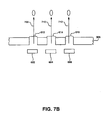
- FIG. 7B a side sectional schematic view is shown of a plurality of heating elements 602, 604, and 606 located in a common firing chamber, and corresponding aligned bores 612, 614, and 616, respectively, formed through, for example, an orifice layer 305.
- bores 612, 614, and 616 are disposed aligned with (i.e. centered with respect to) heating element 602, heating element 604, and heating element 606, respectively.
- fluid which heating element 602 causes to be ejected from the common firing chamber is directed along a trajectory as indicated by arrow 708 which is substantially parallel to the trajectory indicated by arrows 710 and 712.
- fluid which heating element 604 causes to be ejected from the common firing chamber is directed along a trajectory as schematically indicated by arrow 710 which is substantially parallel to the trajectory schematically indicated by arrows 708 and 712.
- fluid which heating element 606 causes to be ejected from the common firing chamber is directed along a trajectory as schematically indicated by arrow 712 which is substantially parallel to the trajectory schematically indicated by arrows 708 and 710.
- FIG. 8A a schematic plan view is shown of one orientation of a plurality of bores on a printhead 802 in which a plurality of heating elements are disposed in a common firing chamber in accordance with various embodiments of the present claimed multi-drop weight firing architecture.
- a schematically depicted printhead 802 is shown having an orifice layer with sets of staggered bores 804a, 804b, and 804c arranged thereon.
- the sets of staggered bores 804a, 804b, and 804c correspond to, for example, bores 612, 614, and 616.
- a scan axis 805 is also shown in Figure 8A for reference.
- FIG. 8B a schematic plan view is shown of another orientation of a set of bores in an orifice layer in which a plurality of heating elements are disposed in a common firing chamber in accordance with various embodiments of the present claimed multi-drop weight firing architecture.
- a schematically depicted orifice layer is shown having a set of staggered bores 808a, 808b, and 808c arranged thereon.
- sets of staggered bores 808a, 808b, and 808c correspond with, for example, bores 612, 614, and 616.
- a scan axis 805 is also shown in Figure 8B for reference.
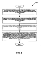
- a flow chart 900 is shown of steps performed during the manufacture of one embodiment of the present multi-drop weight firing architecture.
- the present embodiment forms a first heating element to be disposed within a firing chamber.
- fluid having a first drop weight is ejected from a firing chamber.
- the present embodiment forms a second heating element to be disposed within the same firing chamber in which the first heating element is to be disposed.
- fluid having a second drop weight is ejected from the common firing chamber.
- the first heating element and the second heating element are formed such that the first drop weight is different than the second drop weight.
- the present invention is, however, well suited to forming the first heating element and the second heating element such that the first drop weight is the same as the second drop weight.
- the present invention also includes the step of forming a first bore proximate the first heating element, wherein the first bore is disposed to direct fluid having the first drop weight when ejected from the firing chamber.
- Such an embodiment also typically includes the step of forming a second bore proximate the second heating element, wherein the second bore is disposed to direct fluid having the second drop weight when ejected from the firing chamber. In so doing, the present embodiment is able to direct the fluid having the first drop weight and the fluid having the second drop weight in a desired direction.
- step 906 the present embodiment then electrically couples first drive circuitry with the first heating element.
- the first drive circuitry is for controlling the first heating element.
- the present embodiment then electrically couples second drive circuitry with the second heating element.
- the electrical coupling is performed such that, ultimately, the first drive circuitry and the second drive circuitry are separately addressable.
- the fluid having the first drop weight is ejectable from the firing chamber substantially concurrently or separately from the fluid having the second drop weight.
- the present embodiment of the multi-drop weight firing architecture is compatible with existing firing chamber, printhead, and printer component fabrication processes. That is, the present embodiment of the multi-drop weight firing architecture can be manufactured using existing fabrication processes and equipment.
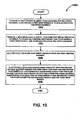
- a flow chart 1000 is shown of steps performed during the manufacture of one embodiment of the present multi-drop weight firing architecture.
- the present embodiment forms a first heating element to be disposed within a firing chamber.
- fluid having a first drop weight is ejected from a firing chamber.
- the present embodiment forms a second heating element to be disposed within the same firing chamber in which the first heating element is to be disposed.
- fluid having a second drop weight is ejected from the common firing chamber and also fluid having a third drop weight is ejected from the common firing chamber.
- the first heating element and the second heating element are formed such that the first drop weight is different than the second and third drop weight combined or individually.
- the present invention is, however, well suited to forming the first heating element and the second heating element such that the first drop weight is the same as the second and third drop weight combined or individually.
- the present invention also includes the step of forming a first bore proximate the first heating element, wherein the first bore is disposed to direct fluid having the first drop weight when ejected from the firing chamber.
- Such an embodiment also typically includes the step of forming a second bore proximate the second heating element and a third bore proximate the third heating element.
- the second bore is disposed to direct fluid having the second drop weight when ejected from the firing chamber and the third bore is disposed to direct fluid having the third drop weight when ejected from the firing chamber.
- the present embodiment is able to direct the fluid having the first drop weight, the second drop weight, and the fluid having the third drop weight in a desired direction.
- step 1006 the present embodiment then electrically couples first drive circuitry with the first heating element.
- the first drive circuitry is for controlling the first heating element.
- the present embodiment then electrically couples second drive circuitry with the second heating element.
- the electrical coupling is performed such that, ultimately, the first drive circuitry and the second drive circuitry are separately addressable.
- the fluid having the first drop weight is ejectable from the firing chamber substantially concurrently or separately from the fluid having the second drop weight and the fluid having the third drop weight.
- the present multi-drop weight firing architecture is compatible with existing firing chamber, printhead, and printer component fabrication processes. That is, the present multi-drop weight firing architecture can be manufactured using existing fabrication processes and equipment.
- an embodiment of the present invention provides a firing architecture which is able to efficiently meet the resolution and technological demands of sophisticated printing systems.
Landscapes
- Particle Formation And Scattering Control In Inkjet Printers (AREA)
- Ink Jet (AREA)
- Nozzles (AREA)
Abstract
Description
Claims (11)
- A fluid ejection device comprising:a first drop ejector (303 and 406) associated with a firing chamber (301), said first drop ejector configured to cause fluid having a first drop weight to be ejected from said firing chamber, wherein said first drop ejector includes a first heating element (303) and first drive circuitry (406) electrically coupled with said first heating element;a first bore (317) disposed within an orifice layer (305) disposed proximate said first drop ejector, said first bore associated with said first drop ejector;a second drop ejector (304 and 408) associated with said firing chamber, said second drop ejector configured to cause fluid having a second drop weight to be ejected from said firing chamber, wherein said second drop ejector includes a second heating element (304) and second drive circuitry (408) electrically coupled with said second heating element; anda second bore (319) disposed within said orifice layer disposed proximate said second drop ejector, said second bore associated with said second drop ejector.
- The fluid ejection device of Claim 1 wherein said first heating element and said second heating element at least partially define said first drop weight and said second drop weight, respectively.
- The fluid ejection device of Claim 1 wherein said first drive circuitry and said second drive circuitry at least partially define said first drop weight and said second drop weight, respectively.
- The fluid ejection device of Claim 1 wherein said first bore and said second bore at least partially define said first drop weight and said second drop weight, respectively.
- The fluid ejection device of Claim 1 wherein said first drive circuitry and said second drive circuitry are separately addressable such that said fluid having said first drop weight is ejectable from said firing chamber at least one of substantially concurrently and separately from said fluid having said second drop weight.
- The fluid ejection device of Claim 1 wherein said first drop weight is different from said second drop weight.
- The fluid ejection device of Claim 1 wherein said first bore is disposed to direct said fluid having said first drop weight when ejected from said firing chamber; and
wherein said second bore is disposed to direct said fluid having said second drop weight when ejected from said firing chamber such that said first bore and said second bore direct said fluid having said first drop weight and said fluid having said second drop weight in a desired direction. - The fluid ejection device of Claim 1 wherein said second heating element is further configured to cause fluid having a third drop weight to be ejected from said firing chamber.
- The fluid ejection device of Claim 8 wherein said first drop weight, said second drop weight, and said third drop weight are each different.
- The fluid ejection device of Claim 8 wherein said first drive circuitry and said second drive circuitry are separately addressable such that said fluid having said first drop weight is ejectable from said firing chamber at least one of substantially concurrently and separately from said fluid having said second drop weight and said third drop weight.
- The fluid ejection device of Claim 8, wherein said first bore is disposed to direct said fluid having said first drop weight when ejected from said firing chamber; wherein said second bore is disposed to direct said fluid having said second drop weight when ejected from said firing chamber; and
a third bore (606) disposed to direct said fluid having said third drop weight when ejected from said firing chamber such that said first bore, said second bore, and said third bore direct said fluid having said first drop weight, said fluid having said second drop weight, and said fluid having said third drop weight in a desired direction.
Applications Claiming Priority (2)
| Application Number | Priority Date | Filing Date | Title |
|---|---|---|---|
| US387149 | 1999-08-31 | ||
| US10/387,149 US6808241B2 (en) | 2003-03-11 | 2003-03-11 | Fluid ejection device |
Publications (3)
| Publication Number | Publication Date |
|---|---|
| EP1464495A2 true EP1464495A2 (en) | 2004-10-06 |
| EP1464495A3 EP1464495A3 (en) | 2007-01-03 |
| EP1464495B1 EP1464495B1 (en) | 2010-04-14 |
Family
ID=32850510
Family Applications (1)
| Application Number | Title | Priority Date | Filing Date |
|---|---|---|---|
| EP03022937A Expired - Lifetime EP1464495B1 (en) | 2003-03-11 | 2003-10-09 | Fluid ejection device |
Country Status (4)
| Country | Link |
|---|---|
| US (1) | US6808241B2 (en) |
| EP (1) | EP1464495B1 (en) |
| JP (1) | JP4538249B2 (en) |
| DE (1) | DE60332088D1 (en) |
Cited By (2)
| Publication number | Priority date | Publication date | Assignee | Title |
|---|---|---|---|---|
| WO2011142748A1 (en) | 2010-05-11 | 2011-11-17 | Hewlett-Packard Development Company, L.P. | Multi-mode printing |
| CN103328222A (en) * | 2011-01-31 | 2013-09-25 | 惠普发展公司,有限责任合伙企业 | Fluid ejection device having firing chamber with contoured floor |
Families Citing this family (8)
| Publication number | Priority date | Publication date | Assignee | Title |
|---|---|---|---|---|
| US6902255B1 (en) * | 1998-10-16 | 2005-06-07 | Silverbrook Research Pty Ltd | Inkjet printers |
| US7419250B2 (en) * | 1999-10-15 | 2008-09-02 | Silverbrook Research Pty Ltd | Micro-electromechanical liquid ejection device |
| US7815291B2 (en) * | 1998-10-16 | 2010-10-19 | Silverbrook Research Pty Ltd | Printhead integrated circuit with low drive transistor to nozzle area ratio |
| US7249815B2 (en) * | 2004-01-30 | 2007-07-31 | Hewlett-Packard Development Company, L.P. | Nozzle distribution |
| RU2470790C1 (en) * | 2008-12-08 | 2012-12-27 | Хьюлетт-Паккард Дивелопмент Компани, Л.П. | Fluid ejector |
| US9289978B2 (en) | 2008-12-08 | 2016-03-22 | Hewlett-Packard Development Company, L.P. | Fluid ejection device |
| WO2016014082A1 (en) * | 2014-07-25 | 2016-01-28 | Hewlett-Packard Development Company, L.P. | Printhead with a number of memristor cells and a number of firing cells coupled to a shared fire line |
| WO2016018199A1 (en) * | 2014-07-26 | 2016-02-04 | Hewlett-Packard Development Company, L.P. | Printhead with a number of memristor cells and a parallel current distributor |
Family Cites Families (12)
| Publication number | Priority date | Publication date | Assignee | Title |
|---|---|---|---|---|
| DE69534683T2 (en) * | 1994-12-29 | 2006-07-06 | Canon K.K. | Ink jet head with various heating elements per nozzle and ink jet printer using the same |
| US6447088B2 (en) * | 1996-01-16 | 2002-09-10 | Canon Kabushiki Kaisha | Ink-jet head, an ink-jet-head cartridge, an ink-jet apparatus and an ink-jet recording method used in gradation recording |
| US6099108A (en) | 1997-03-05 | 2000-08-08 | Hewlett-Packard Company | Method and apparatus for improved ink-drop distribution in ink-jet printing |
| DE69733043T2 (en) | 1996-06-28 | 2006-03-09 | Canon K.K. | A method of driving a recording head having a plurality of heating elements per nozzle |
| US6020905A (en) | 1997-01-24 | 2000-02-01 | Lexmark International, Inc. | Ink jet printhead for drop size modulation |
| US6276775B1 (en) | 1999-04-29 | 2001-08-21 | Hewlett-Packard Company | Variable drop mass inkjet drop generator |
| US6137502A (en) * | 1999-08-27 | 2000-10-24 | Lexmark International, Inc. | Dual droplet size printhead |
| US6318847B1 (en) * | 2000-03-31 | 2001-11-20 | Hewlett-Packard Company | Segmented heater resistor for producing a variable ink drop volume in an inkjet drop generator |
| KR100416544B1 (en) | 2001-03-15 | 2004-02-05 | 삼성전자주식회사 | Bubble-jet type ink-jet print head with double heater |
| US6390600B1 (en) | 2001-04-30 | 2002-05-21 | Hewlett-Packard Company | Ink jet device having variable ink ejection |
| US6711806B2 (en) * | 2001-05-14 | 2004-03-30 | Hewlett-Packard Development Company, L.P. | Method of manufacturing a thermal fluid jetting apparatus |
| TW491734B (en) * | 2001-06-28 | 2002-06-21 | Acer Comm & Multimedia Inc | Microinjector for ejecting droplets of different sizes |
-
2003
- 2003-03-11 US US10/387,149 patent/US6808241B2/en not_active Expired - Fee Related
- 2003-10-09 EP EP03022937A patent/EP1464495B1/en not_active Expired - Lifetime
- 2003-10-09 DE DE60332088T patent/DE60332088D1/en not_active Expired - Lifetime
-
2004
- 2004-03-11 JP JP2004069007A patent/JP4538249B2/en not_active Expired - Fee Related
Cited By (6)
| Publication number | Priority date | Publication date | Assignee | Title |
|---|---|---|---|---|
| WO2011142748A1 (en) | 2010-05-11 | 2011-11-17 | Hewlett-Packard Development Company, L.P. | Multi-mode printing |
| EP2569159A4 (en) * | 2010-05-11 | 2014-05-21 | Hewlett Packard Development Co | MULTIMODE PRINTING |
| US8864264B2 (en) | 2010-05-11 | 2014-10-21 | Hewlett-Packard Development Company, L.P. | Multi-mode printing |
| AU2010352862B2 (en) * | 2010-05-11 | 2015-01-22 | Hewlett-Packard Development Company, L.P. | Multi-mode printing |
| EP2962851A1 (en) * | 2010-05-11 | 2016-01-06 | Hewlett-Packard Development Company, L.P. | Multi-mode printing |
| CN103328222A (en) * | 2011-01-31 | 2013-09-25 | 惠普发展公司,有限责任合伙企业 | Fluid ejection device having firing chamber with contoured floor |
Also Published As
| Publication number | Publication date |
|---|---|
| US6808241B2 (en) | 2004-10-26 |
| JP2004268590A (en) | 2004-09-30 |
| JP4538249B2 (en) | 2010-09-08 |
| DE60332088D1 (en) | 2010-05-27 |
| EP1464495A3 (en) | 2007-01-03 |
| EP1464495B1 (en) | 2010-04-14 |
| US20040179065A1 (en) | 2004-09-16 |
Similar Documents
| Publication | Publication Date | Title |
|---|---|---|
| JP4236251B2 (en) | Inkjet head | |
| CA2228780C (en) | Single pass ink jet printer | |
| EP1314562B1 (en) | Inkjet printhead assembly having very high drop rate generation | |
| EP1048465B1 (en) | Improved printhead | |
| JP3848218B2 (en) | Inkjet recording head | |
| EP0569156B1 (en) | Optimizing print quality and reliability in a CYMK printing system | |
| US6808241B2 (en) | Fluid ejection device | |
| JP4439319B2 (en) | Liquid ejection head, liquid cartridge, liquid ejection apparatus, and image forming apparatus | |
| JP4236250B2 (en) | Inkjet head | |
| US9434156B2 (en) | Method of inkjet printing and maintaining nozzle hydration | |
| JP2004001490A (en) | Inkjet head | |
| US20070229597A1 (en) | Liquid ejection head and image forming apparatus | |
| EP1473160B1 (en) | Fluid ejection device | |
| US7354139B2 (en) | Printhead substrate, printhead, head cartridge, and printing apparatus | |
| JP2000103045A (en) | Ink jet printer and printing method | |
| EP1514685B1 (en) | Liquid discharge apparatus and inkjet recording apparatus | |
| EP1331099B1 (en) | System for reducing the effect of aerodynamic induced errors in a drop-on-demand printing system | |
| US7681998B2 (en) | Laminated piezoelectric element, liquid droplet ejection head using same, and image forming apparatus comprising same | |
| JP4792848B2 (en) | Inkjet recording device | |
| US7252372B2 (en) | Liquid ejection apparatus and ejection control method | |
| JP4280502B2 (en) | Recording apparatus and recording method | |
| JP2001301167A (en) | Ink jet recording head and ink jet recording apparatus | |
| JP2009012338A (en) | Ink ejection apparatus and control method thereof | |
| JP2005288914A (en) | Liquid-droplet discharge head, liquid-droplet discharge device and image forming apparatus | |
| JP2001191524A (en) | Ink jet recording head and ink jet recording apparatus |
Legal Events
| Date | Code | Title | Description |
|---|---|---|---|
| PUAI | Public reference made under article 153(3) epc to a published international application that has entered the european phase |
Free format text: ORIGINAL CODE: 0009012 |
|
| AK | Designated contracting states |
Kind code of ref document: A2 Designated state(s): AT BE BG CH CY CZ DE DK EE ES FI FR GB GR HU IE IT LI LU MC NL PT RO SE SI SK TR |
|
| AX | Request for extension of the european patent |
Extension state: AL LT LV MK |
|
| PUAL | Search report despatched |
Free format text: ORIGINAL CODE: 0009013 |
|
| AK | Designated contracting states |
Kind code of ref document: A3 Designated state(s): AT BE BG CH CY CZ DE DK EE ES FI FR GB GR HU IE IT LI LU MC NL PT RO SE SI SK TR |
|
| AX | Request for extension of the european patent |
Extension state: AL LT LV MK |
|
| RIC1 | Information provided on ipc code assigned before grant |
Ipc: B41J 2/14 20060101AFI20040719BHEP Ipc: B41J 2/05 20060101ALI20061124BHEP Ipc: B41J 2/21 20060101ALI20061124BHEP |
|
| 17P | Request for examination filed |
Effective date: 20070116 |
|
| AKX | Designation fees paid |
Designated state(s): DE FR GB NL |
|
| 17Q | First examination report despatched |
Effective date: 20070917 |
|
| GRAP | Despatch of communication of intention to grant a patent |
Free format text: ORIGINAL CODE: EPIDOSNIGR1 |
|
| GRAS | Grant fee paid |
Free format text: ORIGINAL CODE: EPIDOSNIGR3 |
|
| GRAA | (expected) grant |
Free format text: ORIGINAL CODE: 0009210 |
|
| AK | Designated contracting states |
Kind code of ref document: B1 Designated state(s): DE FR GB NL |
|
| REG | Reference to a national code |
Ref country code: GB Ref legal event code: FG4D |
|
| REF | Corresponds to: |
Ref document number: 60332088 Country of ref document: DE Date of ref document: 20100527 Kind code of ref document: P |
|
| REG | Reference to a national code |
Ref country code: NL Ref legal event code: T3 |
|
| PLBE | No opposition filed within time limit |
Free format text: ORIGINAL CODE: 0009261 |
|
| STAA | Information on the status of an ep patent application or granted ep patent |
Free format text: STATUS: NO OPPOSITION FILED WITHIN TIME LIMIT |
|
| 26N | No opposition filed |
Effective date: 20110117 |
|
| REG | Reference to a national code |
Ref country code: FR Ref legal event code: PLFP Year of fee payment: 13 |
|
| PGFP | Annual fee paid to national office [announced via postgrant information from national office to epo] |
Ref country code: GB Payment date: 20150924 Year of fee payment: 13 |
|
| PGFP | Annual fee paid to national office [announced via postgrant information from national office to epo] |
Ref country code: FR Payment date: 20150925 Year of fee payment: 13 |
|
| PGFP | Annual fee paid to national office [announced via postgrant information from national office to epo] |
Ref country code: DE Payment date: 20150922 Year of fee payment: 13 |
|
| PGFP | Annual fee paid to national office [announced via postgrant information from national office to epo] |
Ref country code: NL Payment date: 20150923 Year of fee payment: 13 |
|
| REG | Reference to a national code |
Ref country code: DE Ref legal event code: R119 Ref document number: 60332088 Country of ref document: DE |
|
| REG | Reference to a national code |
Ref country code: NL Ref legal event code: MM Effective date: 20161101 |
|
| GBPC | Gb: european patent ceased through non-payment of renewal fee |
Effective date: 20161009 |
|
| REG | Reference to a national code |
Ref country code: FR Ref legal event code: ST Effective date: 20170630 |
|
| PG25 | Lapsed in a contracting state [announced via postgrant information from national office to epo] |
Ref country code: DE Free format text: LAPSE BECAUSE OF NON-PAYMENT OF DUE FEES Effective date: 20170503 Ref country code: FR Free format text: LAPSE BECAUSE OF NON-PAYMENT OF DUE FEES Effective date: 20161102 Ref country code: GB Free format text: LAPSE BECAUSE OF NON-PAYMENT OF DUE FEES Effective date: 20161009 |
|
| PG25 | Lapsed in a contracting state [announced via postgrant information from national office to epo] |
Ref country code: NL Free format text: LAPSE BECAUSE OF NON-PAYMENT OF DUE FEES Effective date: 20161101 |