EP1464417B1 - Method and device for manufacturing slip prevention material of construction machinery - Google Patents
Method and device for manufacturing slip prevention material of construction machinery Download PDFInfo
- Publication number
- EP1464417B1 EP1464417B1 EP02806408A EP02806408A EP1464417B1 EP 1464417 B1 EP1464417 B1 EP 1464417B1 EP 02806408 A EP02806408 A EP 02806408A EP 02806408 A EP02806408 A EP 02806408A EP 1464417 B1 EP1464417 B1 EP 1464417B1
- Authority
- EP
- European Patent Office
- Prior art keywords
- metal plate
- protruding
- central
- concave portion
- concave
- Prior art date
- Legal status (The legal status is an assumption and is not a legal conclusion. Google has not performed a legal analysis and makes no representation as to the accuracy of the status listed.)
- Expired - Lifetime
Links
- 238000010276 construction Methods 0.000 title claims description 15
- 238000000034 method Methods 0.000 title claims description 15
- 238000004519 manufacturing process Methods 0.000 title claims description 13
- 239000000463 material Substances 0.000 title description 2
- 230000002265 prevention Effects 0.000 title 1
- 238000004080 punching Methods 0.000 claims description 28
- 239000002184 metal Substances 0.000 claims description 24
- 230000015572 biosynthetic process Effects 0.000 claims description 2
- 230000007423 decrease Effects 0.000 claims 2
- 229910000831 Steel Inorganic materials 0.000 description 32
- 239000010959 steel Substances 0.000 description 32
- 230000000694 effects Effects 0.000 description 10
- 230000001154 acute effect Effects 0.000 description 7
- 238000003825 pressing Methods 0.000 description 6
- JOYRKODLDBILNP-UHFFFAOYSA-N Ethyl urethane Chemical compound CCOC(N)=O JOYRKODLDBILNP-UHFFFAOYSA-N 0.000 description 5
- XLYOFNOQVPJJNP-UHFFFAOYSA-N water Substances O XLYOFNOQVPJJNP-UHFFFAOYSA-N 0.000 description 3
- 238000007664 blowing Methods 0.000 description 2
- 238000004140 cleaning Methods 0.000 description 2
- 239000000428 dust Substances 0.000 description 2
- 238000012423 maintenance Methods 0.000 description 2
- 230000000717 retained effect Effects 0.000 description 2
- 238000009825 accumulation Methods 0.000 description 1
- 238000009435 building construction Methods 0.000 description 1
- 238000009792 diffusion process Methods 0.000 description 1
- 238000010008 shearing Methods 0.000 description 1
Images






Classifications
-
- B—PERFORMING OPERATIONS; TRANSPORTING
- B21—MECHANICAL METAL-WORKING WITHOUT ESSENTIALLY REMOVING MATERIAL; PUNCHING METAL
- B21D—WORKING OR PROCESSING OF SHEET METAL OR METAL TUBES, RODS OR PROFILES WITHOUT ESSENTIALLY REMOVING MATERIAL; PUNCHING METAL
- B21D22/00—Shaping without cutting, by stamping, spinning, or deep-drawing
- B21D22/02—Stamping using rigid devices or tools
- B21D22/04—Stamping using rigid devices or tools for dimpling
-
- B—PERFORMING OPERATIONS; TRANSPORTING
- B21—MECHANICAL METAL-WORKING WITHOUT ESSENTIALLY REMOVING MATERIAL; PUNCHING METAL
- B21D—WORKING OR PROCESSING OF SHEET METAL OR METAL TUBES, RODS OR PROFILES WITHOUT ESSENTIALLY REMOVING MATERIAL; PUNCHING METAL
- B21D35/00—Combined processes according to or processes combined with methods covered by groups B21D1/00 - B21D31/00
-
- B—PERFORMING OPERATIONS; TRANSPORTING
- B60—VEHICLES IN GENERAL
- B60P—VEHICLES ADAPTED FOR LOAD TRANSPORTATION OR TO TRANSPORT, TO CARRY, OR TO COMPRISE SPECIAL LOADS OR OBJECTS
- B60P7/00—Securing or covering of load on vehicles
- B60P7/06—Securing of load
- B60P7/08—Securing to the vehicle floor or sides
- B60P7/0884—Securing to the vehicle floor or sides by increasing the friction between the load and the surface
Definitions
- the present invention relates to the technical fields of a method and an apparatus for manufacturing a slip stopper employed for a construction machine such as a hydraulic excavator.
- a slip stopper with a slip stopping function is occasionally used for floors, passageways, and stairs in building structures, floors and steps of buses, trucks and special vehicles, decks of railroad vehicles and ships, and scaffolding at construction sites.
- a slip stopper for example, shown in Figs. 10 , has been conventionally known.
- This is a so-called striped steel plate that has a plurality of projections 51 molded in continuous patterned shape, and a corresponding slip stopping effect can be expected in the case of normal scaffolding.
- the height of the projections 51 of this striped steel plate is low and curved, so that a more reliable slip stopper is required when workers step on a cover covering the upper surface of a construction machine as a stepping surface during maintenance.
- a slip stopper for construction machines has been provided in which slip stopping parts 53, having raised edges formed by the marginal portion of a through hole 52 stamped out into a circle shape or a star shape, are formed in a running pattern.
- the raised portions of the slip stopping part 53 can be made sufficiently high, and sharp shear planes are formed by means of the stamping-out process, so that a great slip stopping effect can be obtained.
- the slip stopper having the through hole stamped out is used as it is as a cover to cover the upper surface of a construction machine, problems, such as rainwater or dirt entering the inside of the cover, heated air from an engine blowing upward from the cover, or noise diffuses are inevitable. Therefore, a double structure in that a flat steel plate is fixed to the lower side of the slip stopper is employed to prevent the abovementioned problems.
- the double structure increases production processes and costs in comparison with the single structure and, further, poses a problem in that mud or dust entering the through hole of the slip stopper accumulates between the slip stopper and the lower side flat steel plate or in the through hole, and makes cleaning difficult.
- US 3545249 describes a sheet material including a dimple having a concave shape formed in the dimple and a method for making the same.
- FR2742081 describes a grip plate, or "slip stopper" having projections including concave depressions in their surfaces. A method for making such slip stoppers is also described.
- the present invention has been developed to attempt to solve the abovementioned problems.
- a method of manufacturing a slip stopper for a construction machine comprising the steps of: forming a plurality of protruding portions, that are circular in plan view and have a generally arc-shaped section, on a metal plate so as to protrude in the plate thickness direction, and after said step, forming concave portions respectively in the protruding portions by creating shear planes orientated almost perpendicularly to the plate surface of the metal plate whilst ensuring formation of the concave portions does not open through holes in the metal plate, characterised in that the step of forming concave portions comprises the steps of forming a concave portion at a central portion of each protruding portion and drain channels leading away from the central portion to the upper surface of the metal plate, where the bottom portion of the central concave portion is higher than the upper surface of the metal plate and the bottom portion of each drain channel is inclined downwardly from the central portion towards the upper surface of the metal plate.
- a slip stopper manufacturing apparatus for manufacturing a slip stopper for a construction machine, the apparatus comprising a first punching die unit for forming a plurality of protruding portions that are circular in plan view and have a generally arc-shaped section, on the surface of a metal plate so as to protrude in the plate thickness direction, and a second punching die unit for forming concave portions in the upper surface of the protruding portions formed by the first punching die unit by creating shear planes orientated almost perpendicularly to the plate surface of the metal plate without opening through holes in the metal plate, characterised in that the second punching die unit is arranged to form a concave portion at a central portion of each protruding portion and drain channels leading away from the central portion to the upper surface of the metal plate, where the bottom portion of the central concave portion is higher than the upper surface of the metal plate and the bottom portion of each drain channel is inclined downwardly from the central portion towards the upper surface of the metal plate.
- a slip stopper which achieves a great slip stopping effect and can be used for a location where a problem occurs if a through hole is opened therein can be easily manufactured.
- a construction machine (hydraulic excavator) 1 is constructed so that the upper surfaces of a cover 2 covering the upper surface of the construction machine body and a tool box 3 are formed as stepping surfaces on which a worker walks and steps during maintenance, and a slip stopper 4 to which the invention has been applied is used on these stepping surfaces.
- the slip stopper 4 has a plurality of slip stopping parts 6 formed in a vertically and horizontally running pattern on a flat steel plate 5, and in the slip stopping parts 6, a concave portion 8 and drain channels 9 are formed in a protruding portion 7, that protrudes in the plate thickness direction from the upper surface 5a of the steel plate 5, by shear planes 8a, 9a described later.
- the protruding portion 7 is circular in a plan view and has a roughly arc-shaped section.
- a roughly quadrilateral concave portion 8 is formed at the central portion of the upper surface side of this protruding portion 7, and the level of the groove bottom portion of this concave portion 8 is designed so as to be higher than the upper surface 5a of the steel plate 5.
- drain channels 9, that are shaped into concave grooves leading to the upper surface 5a of the steel plate 5 from the concave portion 8 are formed radially, and the groove bottom portions of the drain channels 9 are formed to be inclined from the level which is almost equal to the level of the groove bottom portion of the concave portion 8 at the concave portion 8 side, to become almost equal to the level of the upper surface of the protruding portion 7 at the marginal section of the protruding portion 7, i.e. become highest at the concave portion 8 side and lower toward the marginal side of the protruding portion 7, whereby water or dirt is prevented from accumulating in the concave portion 8.
- portions 8b, 9b that are the back surface sides of the concave portion 8 and the drain channels 9 protrude downward and become concave in a direction opposite to the upper surface side.
- the inner circumferential surface of the concave portion 8 and the groove side surfaces of the drain channels 9 are formed by shear planes 8a, 9a which face almost perpendicularly to the upper surface 5a of the steel plate 5 and have been half-blanked so as not to open a through hole in the steel plate 5. Furthermore, the shear planes 8a, 9a are sheared so that the upper edges are shaped acutely, that is, acute edges are raised.
- the first punching die unit 10 is for forming the protruding portion 7 on the steel plate 5, and comprises a punch assembly 12, a die assembly 13, and a striker 14.
- the punch assembly 12 comprises a punch 16 for forming a protruding portion, to be fitted in a guide hole 15a opened in an upper base 15 in a manner enabling it to move up and down, a flange 18 integrally attached to the upper end of the punch 16 via a bolt 17, a punch head 20 integrally attached to the upper side of the flange 18 via a bored bolt 19, a support member 22 which is supported by a guide bolt 21 fixed to the upper base 15 in a manner enabling it to move up and down, and comes into contact with the flange 18 from below, and a spring 23 which presses the support member 22 upward, etc.
- the die assembly 13 comprises a die 25 for forming a protruding portion, fixed to a lower base 24, a stripper bolt 26 which is fastened to the die 25 with the head downward, a urethane spring 27 through which the stripper bolt 26 is inserted, upper and lower collars 28, 29 through which the stripper bolt 26 is inserted while the collars are positioned at the upper side and the lower side, and an ejector plate 31 which is fixed to the upper collar 28 via an ejector bolt 54 and guided to the die 25 via a stopper bolt 30 in a manner enabling it to move up and down for a predetermined distance.
- the punch 16 is positioned at a moved-up position separated from the die 25, i.e. withdrawn inside the guide hole 15a of the upper base 15 because the support member 22 that has been retained at a predetermined position by the pressing force of the spring 23 is in contact with the flange 18 from below. Further, the ejector plate 31 is positioned by the pressing force of the urethane spring 27 so that the upper end of the ejector plate 31 is at almost the same height as the upper end of the die 25.
- the punch 16 moves down to project downward from the guide hole 15a, and a protruding portion 7 is formed on the steel plate 5 by being pressed by the punch 16 that has moved down and the die 25.
- the ejector plate 31 is moved down by being pressed by the punch 16 via the steel plate 5.
- the ejector plate 31 is moved up by the pressing force of the urethane spring 27 to separate the steel plate 5 from the die 25.
- the second punching die unit 11 is for forming the concave portion 8 and drain channels 9 in the protruding portion 7 formed by the first punching die unit 10, and comprises, as in the case of the abovementioned first punching die unit 10, a punch assembly 32, a die assembly 33, and a striker 34.
- the punch assembly 32 of this second punching die unit 11 comprises a punch guide 36 which is fitted in a guide hole 35a opened in an upper base 35 in a manner enabling it to move up and down, a flange part 36b which is integrally formed at the upper end of the punch guide 36, a stripper plate 38 which is fastened to the lower end of the punch guide 36 via a stopper bolt 37, a punch 39 for forming a concave portion and drain channels, to be inserted through the cylindrical hole portions 36a, 38a opened in the punch guide 36 and the stripper plate 38 in a manner enabling it to move up and down so that the upper end projects upward from the flange part 36b, and a stripping spring 40 interposed between the upper end of the punch 39 and the flange part 36b, a support member 42 which is guided by a guide bolt 41 fixed to the upper base 35 in a manner enabling the support member 42 to move up and down, and comes into contact with the flange part 36b from below, and a spring 43 which presses the
- the die assembly 33 comprises a die 45 for forming a concave portion and drain channels, fixed to the lower base 44, a stripper bolt 46 that is the same as in the first punching die unit 10, a urethane spring 47, upper and lower collars 48, 49, and an ejector plate 50, etc.
- the support member 42 is retained at a predetermined position by the pressing force of the spring 43 which is in contact with the flange part 36b from below.
- the punch guide 36 is positioned at a moved-up position separated from the die 45 so that the stripper plate 38 is withdrawn inside the guide hole 35a opened in the upper base 35.
- the punch 39 withdraws into the cylindrical hole portion 38a of the stripper plate 38 due to the pressing force of the stripping spring 40.
- the ejector plate 50 is positioned by the pressing force of the urethane spring 47 so that the upper surface of the ejector plate 50 is at nearly the same height as that of the upper end of the die 45.
- the punch 39 and the punch guide 36 move down together first, and accordingly, the stripper plate 38 projects downward from the guide hole 35a of the upper base 35 and the stripper plate 38 comes into contact with the upper surface 5a of the steel plate 5, whereby the steel plate upper surface 5a is pressed by the stripper plate 38.
- the punch 39 moves down alone and the punch 39 that has moved down and the die 45 form the concave portion 8 and the drain channels 9 in the protruding portion 7.
- the inner circumferential surface of the concave portion 8 and the groove side surfaces of the drain channels 9 are formed by, as mentioned above, shear planes 8a, 9a that face almost perpendicularly to the upper surface 5a of the steel plate 5 and have been half-blanked so as not to open a through hole in the steel plate 5.
- shear planes 8a, 9a that face almost perpendicularly to the upper surface 5a of the steel plate 5 and have been half-blanked so as not to open a through hole in the steel plate 5.
- acute edges can be formed at the upper edges of the shear plates 8a, 9a.
- the stripper plate 38 and the ejector plate 50 act to separate the steel plate 5 from the punch 39 and the die 45 as in the same manner as the ejector 31 of the first punching die unit 10 mentioned above.
- first and second punching die units 10, 11 are attached to the turret of a turret punch press that is not shown, and the steel plate 5 is supported on the table of the turret punch press, and the second process for forming the concave portion 8 and the drain channels 9 is carried out successively from the first process by moving the turret or the table for positioning.
- a concave portion 8 is formed at the central portion of the protruding portion 7 that protrudes in the plate thickness direction from the upper surface of the steel plate 5.
- Drain channels 9, shaped into concave grooves, are formed radially from the concave portion 8 so as to lead to the upper surface 5a of the steel plate 5.
- the concave portion 8 and drain channels 9 are formed by shear planes 8a, 9a that face almost perpendicularly to the upper surface 5a of the steel plate 5 and have been half-blanked so as not to open a through hole in the steel plate 5.
- the shear planes 8a, 9a can achieve an excellent reliable slip stopping effect because their protrusions become high from the steel plate upper surface 5a according to the protrusion height of the protruding portion 7, and the upper edges are acute.
- the angles between each shear plane 8a and the upper surface of a protruding portion 7 and between each shear plane 9a and the upper surface of the protruding portion 7 become smaller to become a more acute angle as the inclination of the protruding portion 7 increases. Because as these angles become smaller to be a more acute angle, more acute edges can be raised at the upper edges of the shear planes 8a, 9a, the slip stopping effect can be further improved.
- the drain channels 9 are formed to be inclined, the slip stopping effect is not lost by the accumulation of water or dirt in the concave portion 8, cleaning can be easily carried out even if dirt or dust accumulates in the concave portion 8 or the drain channels 9, and as the groove side surfaces of the drain channels 9 are formed by shear planes 9a, the abovementioned slip stopping effect is further increased.
- the slip stopping part 6 has a great slip stopping effect and does not open a through hole in the steel plate 5, and to form this slip stopping part 6, the second process for forming the concave portion 8 and the drain channels 9 by the second punching die unit 11 is carried out after the first process for forming the protruding portion 7 by the first punching die unit 10.
- the protruding portion 7 can be formed to be sufficiently high above the surface 5a of the steel plate 5, the stress to be applied to the steel plate 5 when shearing the protruding portion 7 by means of half blanking can be reduced, and acute edges can be raised at the upper edges of the shear planes 8a, 9a, whereby an excellent slip stopping effect can be achieved as mentioned above.
- the present invention can be widely applied in technical fields of a method and an apparatus for manufacturing a slip stopper for various footings requiring a device to prevent slipping, such as stepping surfaces of construction machines, floors, passageways, and stairs of building constructions, floors and steps of buses, trucks, and special vehicles, decks of railroad vehicles and ships, scaffolding at construction sites, etc.
- This invention can also be used for a location where a problem occurs if a through hole is opened therein, and is useful in a case where it is necessary to readily manufacture a slip stopper having a great slip stopping effect at low cost.
Landscapes
- Engineering & Computer Science (AREA)
- Mechanical Engineering (AREA)
- Transportation (AREA)
- Punching Or Piercing (AREA)
- Sewage (AREA)
- Component Parts Of Construction Machinery (AREA)
- Floor Finish (AREA)
- Body Structure For Vehicles (AREA)
- Shaping Metal By Deep-Drawing, Or The Like (AREA)
- Road Paving Structures (AREA)
Description
- The present invention relates to the technical fields of a method and an apparatus for manufacturing a slip stopper employed for a construction machine such as a hydraulic excavator.
- Generally, a slip stopper with a slip stopping function is occasionally used for floors, passageways, and stairs in building structures, floors and steps of buses, trucks and special vehicles, decks of railroad vehicles and ships, and scaffolding at construction sites. Such a slip stopper, for example, shown in
Figs. 10 , has been conventionally known. This is a so-called striped steel plate that has a plurality ofprojections 51 molded in continuous patterned shape, and a corresponding slip stopping effect can be expected in the case of normal scaffolding. However, the height of theprojections 51 of this striped steel plate is low and curved, so that a more reliable slip stopper is required when workers step on a cover covering the upper surface of a construction machine as a stepping surface during maintenance. - Therefore, as shown in
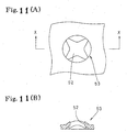
Figs. 11 , a slip stopper for construction machines has been provided in whichslip stopping parts 53, having raised edges formed by the marginal portion of athrough hole 52 stamped out into a circle shape or a star shape, are formed in a running pattern. In this slip stopper, the raised portions of theslip stopping part 53 can be made sufficiently high, and sharp shear planes are formed by means of the stamping-out process, so that a great slip stopping effect can be obtained. - If the slip stopper having the through hole stamped out is used as it is as a cover to cover the upper surface of a construction machine, problems, such as rainwater or dirt entering the inside of the cover, heated air from an engine blowing upward from the cover, or noise diffuses are inevitable. Therefore, a double structure in that a flat steel plate is fixed to the lower side of the slip stopper is employed to prevent the abovementioned problems. However, the double structure increases production processes and costs in comparison with the single structure and, further, poses a problem in that mud or dust entering the through hole of the slip stopper accumulates between the slip stopper and the lower side flat steel plate or in the through hole, and makes cleaning difficult. These problems are aimed to be solved by the invention.
-
US 3545249 describes a sheet material including a dimple having a concave shape formed in the dimple and a method for making the same. -
FR2742081 - In view of the abovementioned circumstances, the present invention has been developed to attempt to solve the abovementioned problems.
- According to one aspect of the invention there is provided a method of manufacturing a slip stopper for a construction machine, comprising the steps of: forming a plurality of protruding portions, that are circular in plan view and have a generally arc-shaped section, on a metal plate so as to protrude in the plate thickness direction, and after said step, forming concave portions respectively in the protruding portions by creating shear planes orientated almost perpendicularly to the plate surface of the metal plate whilst ensuring formation of the concave portions does not open through holes in the metal plate, characterised in that the step of forming concave portions comprises the steps of forming a concave portion at a central portion of each protruding portion and drain channels leading away from the central portion to the upper surface of the metal plate, where the bottom portion of the central concave portion is higher than the upper surface of the metal plate and the bottom portion of each drain channel is inclined downwardly from the central portion towards the upper surface of the metal plate.
- According to another aspect of the present invention there is provided a slip stopper manufacturing apparatus for manufacturing a slip stopper for a construction machine, the apparatus comprising a first punching die unit for forming a plurality of protruding portions that are circular in plan view and have a generally arc-shaped section, on the surface of a metal plate so as to protrude in the plate thickness direction, and a second punching die unit for forming concave portions in the upper surface of the protruding portions formed by the first punching die unit by creating shear planes orientated almost perpendicularly to the plate surface of the metal plate without opening through holes in the metal plate, characterised in that the second punching die unit is arranged to form a concave portion at a central portion of each protruding portion and drain channels leading away from the central portion to the upper surface of the metal plate, where the bottom portion of the central concave portion is higher than the upper surface of the metal plate and the bottom portion of each drain channel is inclined downwardly from the central portion towards the upper surface of the metal plate.
- By using the first and second punching die units, a slip stopper which achieves a great slip stopping effect and can be used for a location where a problem occurs if a through hole is opened therein can be easily manufactured.
-
-
Fig. 1 is a plan view of a construction machine. -
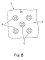
Fig. 2 is a partial plan view of a slip stopper. -
Fig. 3(A) is a plan view of a slip stopping part,Fig. 3(B) is an X-X sectional view of (A), andFig. 3(C) is a Y-Y sectional view of (A). -
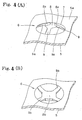
Fig. 4 (A) is a perspective plan view of a slip stopping part, andFig. 4(B) is a perspective bottom view of the slip stopping part. -
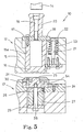
Fig. 5 is a sectional view of a first punching die unit when a striker moves up. -
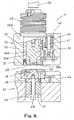
Fig. 6 is a sectional view of the first punching die unit when a striker moves down. -
Fig. 7(A) is a plan view of a protruding portion after a first process is finished, andFig. 7(B) is an X-X sectional view of (A). -
Fig. 8 is a sectional view of a second punching die unit when a striker moves up. -
Fig. 9 is a sectional view of the second punching die unit when the striker moves down. -
Fig. 10(A) is a plan view of a checkered steel plate,Fig. 10(B) is an X-X sectional view ofFig. 10(A), and Fig. 10(C) is a Y-Y sectional view ofFig. 10(A) . -
Fig. 11 (A) is a plan view of a slip stopping part in which a through hole is opened, andFig. 11 (B) is an X-X sectional view ofFig. 11(A) . - Next, an embodiment of the invention is described with reference to the drawings. In the drawings, a construction machine (hydraulic excavator) 1 is constructed so that the upper surfaces of a
cover 2 covering the upper surface of the construction machine body and atool box 3 are formed as stepping surfaces on which a worker walks and steps during maintenance, and a slip stopper 4 to which the invention has been applied is used on these stepping surfaces. - The
slip stopper 4 has a plurality ofslip stopping parts 6 formed in a vertically and horizontally running pattern on aflat steel plate 5, and in theslip stopping parts 6, aconcave portion 8 anddrain channels 9 are formed in aprotruding portion 7, that protrudes in the plate thickness direction from theupper surface 5a of thesteel plate 5, byshear planes - Namely, the
protruding portion 7 is circular in a plan view and has a roughly arc-shaped section. A roughly quadrilateralconcave portion 8 is formed at the central portion of the upper surface side of thisprotruding portion 7, and the level of the groove bottom portion of thisconcave portion 8 is designed so as to be higher than theupper surface 5a of thesteel plate 5. Furthermore, fourdrain channels 9, that are shaped into concave grooves leading to theupper surface 5a of thesteel plate 5 from theconcave portion 8 are formed radially, and the groove bottom portions of thedrain channels 9 are formed to be inclined from the level which is almost equal to the level of the groove bottom portion of theconcave portion 8 at theconcave portion 8 side, to become almost equal to the level of the upper surface of the protrudingportion 7 at the marginal section of theprotruding portion 7, i.e. become highest at theconcave portion 8 side and lower toward the marginal side of theprotruding portion 7, whereby water or dirt is prevented from accumulating in theconcave portion 8. On the other hand, at the lower surface side of the protrudingportion 7,portions concave portion 8 and thedrain channels 9 protrude downward and become concave in a direction opposite to the upper surface side. - Herein, the inner circumferential surface of the
concave portion 8 and the groove side surfaces of thedrain channels 9 are formed byshear planes upper surface 5a of thesteel plate 5 and have been half-blanked so as not to open a through hole in thesteel plate 5. Furthermore, theshear planes - To form the
slip stopping part 6, after a first process in which a protrudingportion 7 is formed using first and secondpunching die units concave portion 8 and thedrain channels 9 are formed. - Namely, the first
punching die unit 10 is for forming the protrudingportion 7 on thesteel plate 5, and comprises apunch assembly 12, adie assembly 13, and astriker 14. Thepunch assembly 12 comprises apunch 16 for forming a protruding portion, to be fitted in aguide hole 15a opened in anupper base 15 in a manner enabling it to move up and down, aflange 18 integrally attached to the upper end of thepunch 16 via abolt 17, apunch head 20 integrally attached to the upper side of theflange 18 via abored bolt 19, asupport member 22 which is supported by aguide bolt 21 fixed to theupper base 15 in a manner enabling it to move up and down, and comes into contact with theflange 18 from below, and aspring 23 which presses thesupport member 22 upward, etc. The dieassembly 13 comprises adie 25 for forming a protruding portion, fixed to alower base 24, astripper bolt 26 which is fastened to thedie 25 with the head downward, aurethane spring 27 through which thestripper bolt 26 is inserted, upper andlower collars stripper bolt 26 is inserted while the collars are positioned at the upper side and the lower side, and anejector plate 31 which is fixed to theupper collar 28 via anejector bolt 54 and guided to the die 25 via astopper bolt 30 in a manner enabling it to move up and down for a predetermined distance. - In the first
punching die unit 10, while thestriker 14 moves up, as shown inFig. 5 , thepunch 16 is positioned at a moved-up position separated from thedie 25, i.e. withdrawn inside theguide hole 15a of theupper base 15 because thesupport member 22 that has been retained at a predetermined position by the pressing force of thespring 23 is in contact with theflange 18 from below. Further, theejector plate 31 is positioned by the pressing force of theurethane spring 27 so that the upper end of theejector plate 31 is at almost the same height as the upper end of thedie 25. - When the
striker 14 is moved down, after thesteel plate 5 is set between thepunch 16 and thedie 25 in a condition where thestriker 14 is moved up, as shown inFig. 6 , thepunch 16 moves down to project downward from theguide hole 15a, and aprotruding portion 7 is formed on thesteel plate 5 by being pressed by thepunch 16 that has moved down and thedie 25. At this point, theejector plate 31 is moved down by being pressed by thepunch 16 via thesteel plate 5. However, in accordance with moving-up of thepunch 16 after forming the protrudingportion 7, theejector plate 31 is moved up by the pressing force of theurethane spring 27 to separate thesteel plate 5 from thedie 25. - On the other hand, the second
punching die unit 11 is for forming theconcave portion 8 anddrain channels 9 in theprotruding portion 7 formed by the firstpunching die unit 10, and comprises, as in the case of the abovementioned firstpunching die unit 10, apunch assembly 32, adie assembly 33, and astriker 34. Thepunch assembly 32 of this secondpunching die unit 11 comprises apunch guide 36 which is fitted in aguide hole 35a opened in anupper base 35 in a manner enabling it to move up and down, a flange part 36b which is integrally formed at the upper end of thepunch guide 36, astripper plate 38 which is fastened to the lower end of thepunch guide 36 via astopper bolt 37, apunch 39 for forming a concave portion and drain channels, to be inserted through thecylindrical hole portions punch guide 36 and thestripper plate 38 in a manner enabling it to move up and down so that the upper end projects upward from the flange part 36b, and a strippingspring 40 interposed between the upper end of thepunch 39 and the flange part 36b, asupport member 42 which is guided by aguide bolt 41 fixed to theupper base 35 in a manner enabling thesupport member 42 to move up and down, and comes into contact with the flange part 36b from below, and aspring 43 which presses thesupport member 42 upward, etc. The dieassembly 33 comprises adie 45 for forming a concave portion and drain channels, fixed to thelower base 44, astripper bolt 46 that is the same as in the firstpunching die unit 10, aurethane spring 47, upper andlower collars ejector plate 50, etc. - When the
striker 34 moves up, in the secondpunching die unit 11, as shown inFig. 8 , thesupport member 42 is retained at a predetermined position by the pressing force of thespring 43 which is in contact with the flange part 36b from below. Thepunch guide 36 is positioned at a moved-up position separated from thedie 45 so that thestripper plate 38 is withdrawn inside theguide hole 35a opened in theupper base 35. Thepunch 39 withdraws into thecylindrical hole portion 38a of thestripper plate 38 due to the pressing force of the strippingspring 40. Furthermore, theejector plate 50 is positioned by the pressing force of theurethane spring 47 so that the upper surface of theejector plate 50 is at nearly the same height as that of the upper end of thedie 45. - When the
striker 34 is moved down, after theprotruding portion 7 of thesteel plate 5 is positioned between thepunch 39 and thedie 45 in a condition where thestriker 34 is moved up, thepunch 39 and thepunch guide 36 move down together first, and accordingly, thestripper plate 38 projects downward from theguide hole 35a of theupper base 35 and thestripper plate 38 comes into contact with theupper surface 5a of thesteel plate 5, whereby the steel plateupper surface 5a is pressed by thestripper plate 38. Next, thepunch 39 moves down alone and thepunch 39 that has moved down and thedie 45 form theconcave portion 8 and thedrain channels 9 in theprotruding portion 7. The inner circumferential surface of theconcave portion 8 and the groove side surfaces of thedrain channels 9 are formed by, as mentioned above,shear planes upper surface 5a of thesteel plate 5 and have been half-blanked so as not to open a through hole in thesteel plate 5. In this case, by setting the clearance between thepunch 39 and thedie 45 to zero, acute edges can be formed at the upper edges of theshear plates - Further, in accordance with moving-up of the
punch 39 after theconcave portion 8 anddrain channels 9 are formed, thestripper plate 38 and theejector plate 50 act to separate thesteel plate 5 from thepunch 39 and thedie 45 as in the same manner as theejector 31 of the firstpunching die unit 10 mentioned above. - In this embodiment, first and second
punching die units steel plate 5 is supported on the table of the turret punch press, and the second process for forming theconcave portion 8 and thedrain channels 9 is carried out successively from the first process by moving the turret or the table for positioning. - In the abovementioned structure, at each
slip stopping part 6, aconcave portion 8 is formed at the central portion of the protrudingportion 7 that protrudes in the plate thickness direction from the upper surface of thesteel plate 5.Drain channels 9, shaped into concave grooves, are formed radially from theconcave portion 8 so as to lead to theupper surface 5a of thesteel plate 5. Theconcave portion 8 anddrain channels 9 are formed byshear planes upper surface 5a of thesteel plate 5 and have been half-blanked so as not to open a through hole in thesteel plate 5. The shear planes 8a, 9a can achieve an excellent reliable slip stopping effect because their protrusions become high from the steel plateupper surface 5a according to the protrusion height of the protrudingportion 7, and the upper edges are acute. In the embodiment, the angles between eachshear plane 8a and the upper surface of a protrudingportion 7 and between eachshear plane 9a and the upper surface of the protrudingportion 7 become smaller to become a more acute angle as the inclination of the protrudingportion 7 increases. Because as these angles become smaller to be a more acute angle, more acute edges can be raised at the upper edges of theshear planes - In this structure, because the
shear planes steel plate 5, problems, such as water or dirt entering inside thecover 2 or thetool box 3, blowing up of heated air from an engine, and noise diffusion to the outside, can be prevented without the conventional double structure with a through hole opened, resulting in a significant cost reduction. - Further, in this structure, because the
drain channels 9 are formed to be inclined, the slip stopping effect is not lost by the accumulation of water or dirt in theconcave portion 8, cleaning can be easily carried out even if dirt or dust accumulates in theconcave portion 8 or thedrain channels 9, and as the groove side surfaces of thedrain channels 9 are formed byshear planes 9a, the abovementioned slip stopping effect is further increased. - Thus, the
slip stopping part 6 has a great slip stopping effect and does not open a through hole in thesteel plate 5, and to form thisslip stopping part 6, the second process for forming theconcave portion 8 and thedrain channels 9 by the second punching dieunit 11 is carried out after the first process for forming the protrudingportion 7 by the first punching dieunit 10. - As a result, the protruding
portion 7 can be formed to be sufficiently high above thesurface 5a of thesteel plate 5, the stress to be applied to thesteel plate 5 when shearing the protrudingportion 7 by means of half blanking can be reduced, and acute edges can be raised at the upper edges of theshear planes - The present invention can be widely applied in technical fields of a method and an apparatus for manufacturing a slip stopper for various footings requiring a device to prevent slipping, such as stepping surfaces of construction machines, floors, passageways, and stairs of building constructions, floors and steps of buses, trucks, and special vehicles, decks of railroad vehicles and ships, scaffolding at construction sites, etc. This invention can also be used for a location where a problem occurs if a through hole is opened therein, and is useful in a case where it is necessary to readily manufacture a slip stopper having a great slip stopping effect at low cost.
Claims (6)
- A method of manufacturing a slip stopper (4) for a construction machine, comprising the steps of:forming a plurality of protruding portions (7), that are circular in plan view and have a generally arc-shaped section, on a metal plate (5) so as to protrude in the plate thickness direction,and after said step, forming concave portions respectively in the protruding portions (7) by creating shear planes (8a, 9a) orientated almost perpendicularly to the plate surface (5a) of the metal plate (5) whilst ensuring formation of the concave portions does not open through holes in the metal plate,characterised in that the step of forming concave portions comprises the steps of forming a concave portion (8) at a central portion of each protruding portion (7) and drain channels(9) leading away from the central portion to the upper surface (5a) of the metal plate (5), where the bottom portion of the central concave portion (8) is higher than the upper surface (5a) of the metal plate (5) and the bottom portion of each drain channel (9) is inclined downwardly from the central portion towards the upper surface (5a) of the metal plate (5).
- A method according to claim 1 in which the concave portion forming step is carried out so that the bottom portion of each drain channel (9) is inclined from a level which is almost equal to the level of the bottom portion of the central concave portion (8) to a level which is almost equal to the level of the upper surface of the protruding portion (7) at a marginal section of the protruding portion 7.
- A method according to claim 1 or claim 2 in which the concave portion forming step is carried out so that the height of the side walls (9a) of the drain channels (9) in each protruding portion (7) decreases from the region of the central concave portion (8) to the marginal section of the protruding portion.
- A slip stopper manufacturing apparatus for manufacturing a slip stopper (4) for a construction machine, the apparatus comprising a first punching die unit (10) for forming a plurality of protruding portions (7) that are circular in plan view and have a generally arc-shaped section, on the surface of a metal plate so as to protrude in the plate thickness direction, and a second punching die unit (11) for forming concave portions (8) in the upper surface of the protruding portions (7) formed by the first punching die unit (10) by creating shear planes orientated almost perpendicularly to the plate surface (5a) of the metal plate without opening through holes in the metal plate, characterised in that the second punching die unit is arranged to form a concave portion (8) at a central portion of each protruding portion (7) and drain channels(9) leading away from the central portion to the upper surface (5a) of the metal plate (5), where the bottom portion of the central concave portion (8) is higher than the upper surface (5a) of the metal plate (5) and the bottom portion of each drain channel (9) is inclined downwardly from the central portion towards the upper surface (5a) of the metal plate (5).
- A slip stopper manufacturing apparatus according to claim 4 in which the second punching die unit (11) is arranged so that the bottom portion of each drain channel (9) is inclined from a level which is almost equal to the level of the bottom portion of the central concave portion (8) to a level which is almost equal to the level of the upper surface of the protruding portion (7) at a marginal section of the protruding portion 7.
- A slip stopper manufacturing apparatus according to claim 4 or claim 5 in which the second punching die unit (11) is arranged so that the height of the side walls (9a) of the drain channels (9) in each protruding portion (7) decreases from the region of the central concave portion (8) to the marginal section of the protruding portion.
Applications Claiming Priority (3)
| Application Number | Priority Date | Filing Date | Title |
|---|---|---|---|
| JP2002002651A JP4113921B2 (en) | 2002-01-09 | 2002-01-09 | Method and apparatus for manufacturing anti-slip material in construction machine |
| JP2002002651 | 2002-01-09 | ||
| PCT/JP2002/011741 WO2003059548A1 (en) | 2002-01-09 | 2002-11-11 | Method and device for manufacturing slip prevention material of construction machinery |
Publications (3)
| Publication Number | Publication Date |
|---|---|
| EP1464417A1 EP1464417A1 (en) | 2004-10-06 |
| EP1464417A4 EP1464417A4 (en) | 2007-03-21 |
| EP1464417B1 true EP1464417B1 (en) | 2008-07-30 |
Family
ID=19190771
Family Applications (1)
| Application Number | Title | Priority Date | Filing Date |
|---|---|---|---|
| EP02806408A Expired - Lifetime EP1464417B1 (en) | 2002-01-09 | 2002-11-11 | Method and device for manufacturing slip prevention material of construction machinery |
Country Status (5)
| Country | Link |
|---|---|
| US (1) | US7021109B2 (en) |
| EP (1) | EP1464417B1 (en) |
| JP (1) | JP4113921B2 (en) |
| CN (1) | CN1260021C (en) |
| WO (1) | WO2003059548A1 (en) |
Families Citing this family (9)
| Publication number | Priority date | Publication date | Assignee | Title |
|---|---|---|---|---|
| JP3684188B2 (en) * | 2001-10-16 | 2005-08-17 | 新キャタピラー三菱株式会社 | Non-slip structure |
| JP4093454B2 (en) * | 2002-01-09 | 2008-06-04 | 新キャタピラー三菱株式会社 | Anti-slip material |
| EP1884403B1 (en) * | 2006-08-01 | 2009-12-09 | Gerd Bär | Platform for a vehicle tailgate lift |
| USD594564S1 (en) | 2007-11-13 | 2009-06-16 | Handi Products, Inc. | Stair tread plate |
| FI20105322A7 (en) * | 2010-03-30 | 2011-10-01 | Illinois Tool Works | Method for producing perforated sheet-like or strip-like pieces for use in the construction industry and piece produced by the method |
| WO2014067533A1 (en) * | 2012-11-02 | 2014-05-08 | Marel A/S | An anti-sticking surface plate structure to be used as a low-friction based material in a food processing apparatus and method for its manufacture |
| CN104741445B (en) * | 2013-12-26 | 2016-12-07 | 襄阳三金模具有限公司 | A kind of manufacture processing method of Triangular Arm |
| WO2016176746A1 (en) * | 2015-05-07 | 2016-11-10 | Cta Australia Pty Ltd | Manufacture of a tactile indicator plate or tile |
| US10953784B2 (en) * | 2018-11-01 | 2021-03-23 | GM Global Technology Operations LLC | Variable friction cargo surface system for vehicles |
Family Cites Families (19)
| Publication number | Priority date | Publication date | Assignee | Title |
|---|---|---|---|---|
| US2159325A (en) * | 1935-09-30 | 1939-05-23 | Guardian Safety Seal Company | Method of rendering sheet metal and sheet metal articles readily severable |
| US3111977A (en) * | 1961-03-29 | 1963-11-26 | Kruger Cornelius Johannes | Method and means for producing holes in metallic members |
| US3545249A (en) * | 1968-04-08 | 1970-12-08 | Dayton Reliable Tool & Mfg Co | Dimple and method of forming same |
| US4043481A (en) * | 1975-07-16 | 1977-08-23 | Continental Can Company, Inc. | Scored metal flap areas |
| US4154184A (en) * | 1976-07-01 | 1979-05-15 | Coors Container Company | Apparatus and methods for manufacture of can end member |
| JPS54155621A (en) * | 1978-05-30 | 1979-12-07 | Yukio Suyama | Foot device in stainless and its preparation |
| JPS5577941A (en) * | 1978-12-06 | 1980-06-12 | Sanshu Press Kogyo Kk | Projection extruding process on wide face of metal plate |
| US4343119A (en) * | 1979-06-18 | 1982-08-10 | Caterpillar Tractor Co. | Beveled lobe anti-skid grating |
| JPS6224562B2 (en) * | 1979-06-18 | 1987-05-29 | Caterpillar Tractor Co | |
| JPS5977512U (en) * | 1983-03-18 | 1984-05-25 | 門真鋼業株式会社 | Striped groove lid with sign |
| JPS60180633A (en) * | 1984-02-28 | 1985-09-14 | Toshiba Corp | Ironing punch for forming flare of fin |
| JPH0357308Y2 (en) * | 1987-10-28 | 1991-12-26 | ||
| JPH0461151U (en) * | 1990-10-01 | 1992-05-26 | ||
| US5934308A (en) * | 1995-10-24 | 1999-08-10 | Bs&B Safety Systems, Inc. | Rupture disk apparatus and methods |
| FR2742081B1 (en) * | 1995-12-11 | 1999-02-26 | Caterpillar Inc | STEP PLATE CONFIGURATION |
| JPH11254059A (en) * | 1998-03-09 | 1999-09-21 | Amada Co Ltd | Manufacture of checkered plate by turret punch press with numerical control unit |
| JP3659615B2 (en) * | 1998-06-11 | 2005-06-15 | アイダエンジニアリング株式会社 | Method and apparatus for forming groove without sinking boss |
| JP2001071044A (en) | 1999-09-01 | 2001-03-21 | Aiwa Co Ltd | Working device and forming method |
| JP2002045928A (en) * | 2000-08-01 | 2002-02-12 | Kawasaki Heavy Ind Ltd | Non-slip plate and manufacturing method thereof |
-
2002
- 2002-01-09 JP JP2002002651A patent/JP4113921B2/en not_active Expired - Fee Related
- 2002-11-11 US US10/475,166 patent/US7021109B2/en not_active Expired - Fee Related
- 2002-11-11 EP EP02806408A patent/EP1464417B1/en not_active Expired - Lifetime
- 2002-11-11 CN CN02809276.7A patent/CN1260021C/en not_active Expired - Fee Related
- 2002-11-11 WO PCT/JP2002/011741 patent/WO2003059548A1/en not_active Ceased
Also Published As
| Publication number | Publication date |
|---|---|
| CN1507376A (en) | 2004-06-23 |
| WO2003059548A1 (en) | 2003-07-24 |
| EP1464417A4 (en) | 2007-03-21 |
| CN1260021C (en) | 2006-06-21 |
| US20040134251A1 (en) | 2004-07-15 |
| JP4113921B2 (en) | 2008-07-09 |
| EP1464417A1 (en) | 2004-10-06 |
| JP2003206553A (en) | 2003-07-25 |
| US7021109B2 (en) | 2006-04-04 |
Similar Documents
| Publication | Publication Date | Title |
|---|---|---|
| EP1464774B1 (en) | Non-slip material | |
| KR101669182B1 (en) | A Method and a Device for the Manufacturing of Washers for Locking and Washer for Locking | |
| EP1464417A1 (en) | Method and device for manufacturing slip prevention material of construction machinery | |
| US7987691B2 (en) | Method and a device for the manufacturing of washers and washer for a locking system | |
| US6189363B1 (en) | Structure of molding tool for manufacturing cooling fins | |
| KR101402996B1 (en) | Progressive type fine blanking press for manufacturing a lock-plate and manufacturing method thereof | |
| JPH0375247B2 (en) | ||
| EP0676279B1 (en) | Press forwardly feed die of metallic gasket | |
| US5444908A (en) | Die for driving pierce nut | |
| KR102349396B1 (en) | Method for manufacturing gratings of various specifications in one press mold, and grating manufactured by the manufacturing method | |
| CN216729153U (en) | Electromechanical wear-resistant sheet forming die with positioning function | |
| JP3196615B2 (en) | Press mold | |
| JPH07185674A (en) | Cavity and ridge forming device for peripheral wall of tubular body | |
| JP4636452B2 (en) | Punch mold | |
| JPH03153480A (en) | Plate drain hole formation | |
| US20210246660A1 (en) | Sealing device for construction, and associated manufacturing method | |
| KR200254459Y1 (en) | a metallic pattern for ridgo roofing tile | |
| CN202659822U (en) | Tension wheel and stamp connecting die thereof | |
| JPH0535285B2 (en) | ||
| JP2006198667A (en) | Mold for punch press and forming method in punch press | |
| KR101760207B1 (en) | A non slip instrument for heavy equipment | |
| JP2500675B2 (en) | METHOD FOR MOLDING HAT-TYPE PRODUCT HAVING EAR FLANGE AND FORMING MOLD | |
| JP3003339U (en) | Metal mold for drawing and drawing up the mouth hole in a multi-process continuous mouth hole machine for metal can top plate | |
| JPH034409Y2 (en) | ||
| JPH0588724U (en) | Press-type cam driver mounting structure |
Legal Events
| Date | Code | Title | Description |
|---|---|---|---|
| PUAI | Public reference made under article 153(3) epc to a published international application that has entered the european phase |
Free format text: ORIGINAL CODE: 0009012 |
|
| 17P | Request for examination filed |
Effective date: 20040625 |
|
| AK | Designated contracting states |
Kind code of ref document: A1 Designated state(s): AT BE BG CH CY CZ DE DK EE ES FI FR GB GR IE IT LI LU MC NL PT SE SK TR |
|
| A4 | Supplementary search report drawn up and despatched |
Effective date: 20070219 |
|
| REG | Reference to a national code |
Ref country code: DE Ref legal event code: 8566 |
|
| 17Q | First examination report despatched |
Effective date: 20070706 |
|
| GRAP | Despatch of communication of intention to grant a patent |
Free format text: ORIGINAL CODE: EPIDOSNIGR1 |
|
| RIN1 | Information on inventor provided before grant (corrected) |
Inventor name: DOI, TSUYOSHI,C/O SHIN CATERPILLAR MITSUBISHI LTD Inventor name: KOUZU, YOSHIHISA,C/O SHIN CATERPILLAR MITSUBISHI L Inventor name: MIYAKE, HIDEYUKI,C/O APROTEC CO., LTD Inventor name: IWASA, KAZUMICHI,C/O SHIN CATERPILLAR MITSUBISHI L Inventor name: SUGIMOTO, MAMORU,C/O APROTEC CO., LTD Inventor name: NAKAJIMA, NORIO,C/O SHIN CATERPILLAR MITSUBISHI LT Inventor name: TSUJI, MASANORI,C/O SHIN CATERPILLAR MITSUBISHI LT Inventor name: OHNO, SHUNJI,C/O SHIN CATERPILLAR MITSUBISHI LTD. |
|
| GRAS | Grant fee paid |
Free format text: ORIGINAL CODE: EPIDOSNIGR3 |
|
| GRAA | (expected) grant |
Free format text: ORIGINAL CODE: 0009210 |
|
| AK | Designated contracting states |
Kind code of ref document: B1 Designated state(s): BE FR GB |
|
| REG | Reference to a national code |
Ref country code: GB Ref legal event code: FG4D |
|
| RAP2 | Party data changed (patent owner data changed or rights of a patent transferred) |
Owner name: CATERPILLAR JAPAN LTD. |
|
| PLBE | No opposition filed within time limit |
Free format text: ORIGINAL CODE: 0009261 |
|
| STAA | Information on the status of an ep patent application or granted ep patent |
Free format text: STATUS: NO OPPOSITION FILED WITHIN TIME LIMIT |
|
| 26N | No opposition filed |
Effective date: 20090506 |
|
| PGFP | Annual fee paid to national office [announced via postgrant information from national office to epo] |
Ref country code: FR Payment date: 20091123 Year of fee payment: 8 Ref country code: GB Payment date: 20091111 Year of fee payment: 8 |
|
| PGFP | Annual fee paid to national office [announced via postgrant information from national office to epo] |
Ref country code: BE Payment date: 20091019 Year of fee payment: 8 |
|
| BERE | Be: lapsed |
Owner name: SHIN CATERPILLAR MITSUBISHI LTD. Effective date: 20101130 |
|
| GBPC | Gb: european patent ceased through non-payment of renewal fee |
Effective date: 20101111 |
|
| REG | Reference to a national code |
Ref country code: FR Ref legal event code: ST Effective date: 20110801 |
|
| PG25 | Lapsed in a contracting state [announced via postgrant information from national office to epo] |
Ref country code: BE Free format text: LAPSE BECAUSE OF NON-PAYMENT OF DUE FEES Effective date: 20101130 |
|
| PG25 | Lapsed in a contracting state [announced via postgrant information from national office to epo] |
Ref country code: FR Free format text: LAPSE BECAUSE OF NON-PAYMENT OF DUE FEES Effective date: 20101130 |
|
| PG25 | Lapsed in a contracting state [announced via postgrant information from national office to epo] |
Ref country code: GB Free format text: LAPSE BECAUSE OF NON-PAYMENT OF DUE FEES Effective date: 20101111 |