EP1464281B1 - Messgerät enthaltende Schuhsohle, und Schuh mit einer solchen Sohle - Google Patents
Messgerät enthaltende Schuhsohle, und Schuh mit einer solchen Sohle Download PDFInfo
- Publication number
- EP1464281B1 EP1464281B1 EP04300096A EP04300096A EP1464281B1 EP 1464281 B1 EP1464281 B1 EP 1464281B1 EP 04300096 A EP04300096 A EP 04300096A EP 04300096 A EP04300096 A EP 04300096A EP 1464281 B1 EP1464281 B1 EP 1464281B1
- Authority
- EP
- European Patent Office
- Prior art keywords
- sole
- sensor
- ring
- face
- shoe
- Prior art date
- Legal status (The legal status is an assumption and is not a legal conclusion. Google has not performed a legal analysis and makes no representation as to the accuracy of the status listed.)
- Expired - Lifetime
Links
- 210000002683 foot Anatomy 0.000 claims description 33
- 238000004458 analytical method Methods 0.000 claims description 11
- 210000000459 calcaneus Anatomy 0.000 claims description 6
- 210000001255 hallux Anatomy 0.000 claims description 4
- 230000008093 supporting effect Effects 0.000 claims description 2
- 230000000284 resting effect Effects 0.000 claims 3
- 210000003789 metatarsus Anatomy 0.000 claims 1
- 238000005259 measurement Methods 0.000 description 18
- 230000000694 effects Effects 0.000 description 9
- 230000009184 walking Effects 0.000 description 8
- 229910052782 aluminium Inorganic materials 0.000 description 6
- XAGFODPZIPBFFR-UHFFFAOYSA-N aluminium Chemical compound [Al] XAGFODPZIPBFFR-UHFFFAOYSA-N 0.000 description 6
- 230000006835 compression Effects 0.000 description 5
- 238000007906 compression Methods 0.000 description 5
- 230000006978 adaptation Effects 0.000 description 4
- 230000005540 biological transmission Effects 0.000 description 3
- 229920001971 elastomer Polymers 0.000 description 3
- 210000001872 metatarsal bone Anatomy 0.000 description 3
- 238000000034 method Methods 0.000 description 3
- 230000007170 pathology Effects 0.000 description 3
- 230000001225 therapeutic effect Effects 0.000 description 3
- 229910000906 Bronze Inorganic materials 0.000 description 2
- 208000021642 Muscular disease Diseases 0.000 description 2
- 201000009623 Myopathy Diseases 0.000 description 2
- 239000004411 aluminium Substances 0.000 description 2
- 230000008901 benefit Effects 0.000 description 2
- 229910052790 beryllium Inorganic materials 0.000 description 2
- 239000010974 bronze Substances 0.000 description 2
- 230000003750 conditioning effect Effects 0.000 description 2
- KUNSUQLRTQLHQQ-UHFFFAOYSA-N copper tin Chemical compound [Cu].[Sn] KUNSUQLRTQLHQQ-UHFFFAOYSA-N 0.000 description 2
- 239000003814 drug Substances 0.000 description 2
- 229940079593 drug Drugs 0.000 description 2
- 239000000806 elastomer Substances 0.000 description 2
- 238000011156 evaluation Methods 0.000 description 2
- 230000005021 gait Effects 0.000 description 2
- 210000000474 heel Anatomy 0.000 description 2
- 239000007924 injection Substances 0.000 description 2
- 239000003158 myorelaxant agent Substances 0.000 description 2
- 230000000926 neurological effect Effects 0.000 description 2
- 230000001575 pathological effect Effects 0.000 description 2
- 230000003405 preventing effect Effects 0.000 description 2
- 230000035945 sensitivity Effects 0.000 description 2
- 230000009182 swimming Effects 0.000 description 2
- 238000013519 translation Methods 0.000 description 2
- 229910000838 Al alloy Inorganic materials 0.000 description 1
- 108030001720 Bontoxilysin Proteins 0.000 description 1
- 229910001369 Brass Inorganic materials 0.000 description 1
- 208000012239 Developmental disease Diseases 0.000 description 1
- 241000196324 Embryophyta Species 0.000 description 1
- LFQSCWFLJHTTHZ-UHFFFAOYSA-N Ethanol Chemical compound CCO LFQSCWFLJHTTHZ-UHFFFAOYSA-N 0.000 description 1
- 206010019468 Hemiplegia Diseases 0.000 description 1
- 241000282414 Homo sapiens Species 0.000 description 1
- RRHGJUQNOFWUDK-UHFFFAOYSA-N Isoprene Chemical compound CC(=C)C=C RRHGJUQNOFWUDK-UHFFFAOYSA-N 0.000 description 1
- 208000008238 Muscle Spasticity Diseases 0.000 description 1
- 208000018737 Parkinson disease Diseases 0.000 description 1
- 241000135309 Processus Species 0.000 description 1
- 229920000297 Rayon Polymers 0.000 description 1
- 208000025747 Rheumatic disease Diseases 0.000 description 1
- 240000008042 Zea mays Species 0.000 description 1
- 230000003321 amplification Effects 0.000 description 1
- 229940035678 anti-parkinson drug Drugs 0.000 description 1
- 239000000939 antiparkinson agent Substances 0.000 description 1
- ATBAMAFKBVZNFJ-UHFFFAOYSA-N beryllium atom Chemical compound [Be] ATBAMAFKBVZNFJ-UHFFFAOYSA-N 0.000 description 1
- 229940053031 botulinum toxin Drugs 0.000 description 1
- 239000010951 brass Substances 0.000 description 1
- 230000002490 cerebral effect Effects 0.000 description 1
- 206010008129 cerebral palsy Diseases 0.000 description 1
- 238000006243 chemical reaction Methods 0.000 description 1
- 239000002131 composite material Substances 0.000 description 1
- 239000004020 conductor Substances 0.000 description 1
- 238000012937 correction Methods 0.000 description 1
- 230000006735 deficit Effects 0.000 description 1
- 230000003412 degenerative effect Effects 0.000 description 1
- 230000002939 deleterious effect Effects 0.000 description 1
- 206010012601 diabetes mellitus Diseases 0.000 description 1
- 208000037265 diseases, disorders, signs and symptoms Diseases 0.000 description 1
- 230000005611 electricity Effects 0.000 description 1
- 238000002567 electromyography Methods 0.000 description 1
- 238000001914 filtration Methods 0.000 description 1
- 230000009975 flexible effect Effects 0.000 description 1
- 229920002457 flexible plastic Polymers 0.000 description 1
- 239000003292 glue Substances 0.000 description 1
- 230000001771 impaired effect Effects 0.000 description 1
- 230000002757 inflammatory effect Effects 0.000 description 1
- 208000014674 injury Diseases 0.000 description 1
- 238000003780 insertion Methods 0.000 description 1
- 230000037431 insertion Effects 0.000 description 1
- 230000035987 intoxication Effects 0.000 description 1
- 231100000566 intoxication Toxicity 0.000 description 1
- 230000009191 jumping Effects 0.000 description 1
- 210000003127 knee Anatomy 0.000 description 1
- 238000013150 knee replacement Methods 0.000 description 1
- 230000004807 localization Effects 0.000 description 1
- 230000033001 locomotion Effects 0.000 description 1
- 230000006738 locomotor deficit Effects 0.000 description 1
- 210000003141 lower extremity Anatomy 0.000 description 1
- 238000012423 maintenance Methods 0.000 description 1
- 238000004519 manufacturing process Methods 0.000 description 1
- 229910052751 metal Inorganic materials 0.000 description 1
- 239000002184 metal Substances 0.000 description 1
- 230000004973 motor coordination Effects 0.000 description 1
- 229940035363 muscle relaxants Drugs 0.000 description 1
- 210000002346 musculoskeletal system Anatomy 0.000 description 1
- 230000002232 neuromuscular Effects 0.000 description 1
- 238000003199 nucleic acid amplification method Methods 0.000 description 1
- 230000003287 optical effect Effects 0.000 description 1
- 239000013307 optical fiber Substances 0.000 description 1
- 230000000399 orthopedic effect Effects 0.000 description 1
- 230000002093 peripheral effect Effects 0.000 description 1
- 239000002985 plastic film Substances 0.000 description 1
- 231100000614 poison Toxicity 0.000 description 1
- 229920001195 polyisoprene Polymers 0.000 description 1
- 230000036316 preload Effects 0.000 description 1
- 230000002265 prevention Effects 0.000 description 1
- 230000003449 preventive effect Effects 0.000 description 1
- 230000008569 process Effects 0.000 description 1
- 230000004224 protection Effects 0.000 description 1
- 239000002964 rayon Substances 0.000 description 1
- 238000011084 recovery Methods 0.000 description 1
- 238000007670 refining Methods 0.000 description 1
- 238000011160 research Methods 0.000 description 1
- 239000005060 rubber Substances 0.000 description 1
- 238000010079 rubber tapping Methods 0.000 description 1
- 230000009183 running Effects 0.000 description 1
- 239000000243 solution Substances 0.000 description 1
- 208000018198 spasticity Diseases 0.000 description 1
- 230000003068 static effect Effects 0.000 description 1
- 238000013456 study Methods 0.000 description 1
- 239000000126 substance Substances 0.000 description 1
- 238000001356 surgical procedure Methods 0.000 description 1
- 238000002560 therapeutic procedure Methods 0.000 description 1
- 238000011541 total hip replacement Methods 0.000 description 1
- 239000003440 toxic substance Substances 0.000 description 1
- 230000008733 trauma Effects 0.000 description 1
- 238000011282 treatment Methods 0.000 description 1
Images


Classifications
-
- A—HUMAN NECESSITIES
- A61—MEDICAL OR VETERINARY SCIENCE; HYGIENE
- A61B—DIAGNOSIS; SURGERY; IDENTIFICATION
- A61B5/00—Measuring for diagnostic purposes; Identification of persons
- A61B5/68—Arrangements of detecting, measuring or recording means, e.g. sensors, in relation to patient
- A61B5/6801—Arrangements of detecting, measuring or recording means, e.g. sensors, in relation to patient specially adapted to be attached to or worn on the body surface
- A61B5/6802—Sensor mounted on worn items
- A61B5/6804—Garments; Clothes
- A61B5/6807—Footwear
-
- A—HUMAN NECESSITIES
- A43—FOOTWEAR
- A43B—CHARACTERISTIC FEATURES OF FOOTWEAR; PARTS OF FOOTWEAR
- A43B13/00—Soles; Sole-and-heel integral units
-
- A—HUMAN NECESSITIES
- A43—FOOTWEAR
- A43B—CHARACTERISTIC FEATURES OF FOOTWEAR; PARTS OF FOOTWEAR
- A43B3/00—Footwear characterised by the shape or the use
- A43B3/34—Footwear characterised by the shape or the use with electrical or electronic arrangements
-
- A—HUMAN NECESSITIES
- A61—MEDICAL OR VETERINARY SCIENCE; HYGIENE
- A61B—DIAGNOSIS; SURGERY; IDENTIFICATION
- A61B5/00—Measuring for diagnostic purposes; Identification of persons
- A61B5/103—Measuring devices for testing the shape, pattern, colour, size or movement of the body or parts thereof, for diagnostic purposes
- A61B5/1036—Measuring load distribution, e.g. podologic studies
- A61B5/1038—Measuring plantar pressure during gait
Definitions
- the present invention relates to an instrumented shoe sole for analysis of walking and a shoe comprising such a sole.
- the sole includes sensors for measuring the forces transmitted to the ground by the arch and reciprocally. It has applications in the city or sport shoe industry to improve the effectiveness of shoes and / or their comfort as well as in preventive or curative diagnostic activities on healthy or pathological subjects.
- the shoe can be used for static and, preferably, dynamic measurements and analyzes.
- walk covers all activity in which the foot intervenes and in particular the walk as such according to its usual definition, running, jumping, dancing, swimming (the shoes then corresponding to fins).
- the term shoe is therefore generic in the context of the invention.
- the solution proposed by the invention proposes to solve these disadvantages.
- the invention therefore relates to an instrumented shoe sole for analyzing the step, the sole having a first face oriented towards the inside of the boot for supporting a sole and a second face opposite to the first intended to bear on a support, especially a floor.
- the sole comprises a set of housings, the housings being open on the first and second faces of the soleplate and each receiving a load cell for measuring a bearing pressure of a surface area of the foot plant, the sensor being disposed between a first rigid plate towards the first face of the sole and a second rigid plate towards the second face of the sole, the plates extending on a surface greater than the surface of the housing, the first plate and the second plate of a given sensor being fixed to said sensor in order to transmit the bearing pressure to said sensor.
- the invention relates to a shoe comprising a sole according to claim 1.
- the sole may comprise any one or more of the preceding features, optionally combined according to all technically feasible possibilities.
- the sole can be removable from the shoe or integrated (that is to say part of the shoe) to said shoe.
- the sole or the shoe is applicable in all fields of biomechanical analysis of the locomotion of healthy or pathological subjects. In particular, it makes it possible to set up the evaluation of treatments, which are necessary to improve the quality of ambulation for patients with locomotor impairment.
- the instrumented soles of the invention for shoes thus have predefined housings for the insertion of force sensors.
- the location of the sensors has been defined in connection with the dynamics of the foot. In the typical embodiment given, there are two sensors under the heel (calcaneus), two under the outer edge of the foot, three under the metatarsal line and one under the hallux, a total of eight sensors. It is understood that the number and arrangement of the sensor housings may vary depending on the objectives of the measurements and the size of the foot.
- the characteristic location of each of these sensors makes it possible to locate the area on which the pressure forces are exerted when walking.
- These sensors consist of an assembly in two parts sliding between them, a housing and its cover, and in which is inserted a torque ring.
- the cover comprises edges which have a length such that they form a stop in case of deformation of the upper ring at a determined level in order to obtain protection against stresses greater than the limit of elasticity of the ring.
- a unidirectional strain gauge mounted in bridge quarter and glued on the free outer face (not in contact with the bottom of the housing or cover) of a beryllium bronze ring, to measure the force received by the sensor. The two plates associated with a given sensor are therefore in correspondence for one with the housing and for the other with the sensor cover.
- the sensor ring plus housing with cover, fixed between two aluminum plates, is arranged in a preferably flexible sole so that the sensor either at the foot-ground interface through its two plates.
- the sensors of the sole or instrumented shoe are associated with a signal conditioning chain with amplification, filtering at least low pass.
- the analog signals of the sensors are converted into digital data by digital analog conversion for transmission and / or recording and / or analysis.
- each of the sensors can calibrate individually by applying a known force on each of the faces of the plates of a sensor. It is also possible to calibrate the sensors globally, for example by placing on the soleplate placed on a rigid plane an artificial standard foot of known weight.
- the calibration concerns both the zero adjustment (measurement at rest) as well as the scale (factor or curve of conversion-stress-measurement), or even linearity (correction factor).
- a calibration is carried out regularly in the time of the sole.
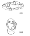
- Figures 1 and 2 show a version of the instrumented shoe with eight sensors.
- the rigid metal plates are attached to the sensors in a removable manner by screwing / unscrewing screws whose heads are visible in the thickness of the plates.
- the removable fixation of the rigid plates on the sensors can be obtained by clipping.
- the screws are preferably conical heads disposed in chamfered holes of the plates.
- the plates are protruding from the surfaces of the sole. Depending on the position of the plate on the sole, the latter may have edges of different shape.
- a plate at the edge of the sole has an edge that follows the contour of the sole.
- a plate in full sole is approximately rectangular.
- Figure 3 shows the arrangement of the plates of the eight sensors on a sole.
- the sensors are preferably located in the support zones of the foot and according to the curvature of the arch, especially to the outer part of the arch to the outer edge of the sole, towards the rear of the foot and the front.
- FIG. 7 is more particularly detailed with, for one of the sensors referenced 6, its first plate 1 and its second plate 5 between which it will be disposed in a housing through the thickness of the sole 8.
- the sensor 6 is shown disassembled in exploded view with its housing 2 having lateral attachment extensions, its cover 4 with edges engaging in the housing and the ring 3 disposed in the housing under the cover.
- the cover can slide in the housing in order to be able to compress the ring according to the stresses exerted between these elements.
- the plates extend on an upper surface to the surface of the housing so as to be supported on at least one of the two faces of the sole. The support of the plates on the soleplate must not disturb the measurement and it will therefore be ensured that the soleplate is sufficiently elastically deformable in thickness and / or that the plates have a sufficient possible approximation amplitude despite the presence of the soleplate.
- FIGs 8 to 17 detail the structure of a sensor.
- the lid 3, at rest, is overflowing the housing 2 so that the forces can act on the ring 3 from and transmitted by the housing and the cover.
- the overflow at rest of the cover relative to the housing can also or alternatively to be a way to limit the constraint.
- the plate on the side of the cover protrudes from the sensor cover and can, when the strain of deformation of the ring is too large, abut against the housing preventing additional stress on the ring.
- the ring 3 preferably comprises at least one (at most two) flat on its outer surface.
- This flat is intended to come into contact with either the bottom of the housing or in contact with the cover to give a stable position to the ring.
- two flats it is understood that they are then diametrically opposite on the outer face of the ring.
- the electrical part of the measurement circuit in the sensor ie the unidirectional strain gauge, is in the form of a track conductor of electricity whose deformation causes a variation of resistance.
- This track is disposed on one of the two free outer faces (not in contact with the bottom of the housing or the cover) of the ring and therefore substantially in a 90 ° position of a flat relative to the axis of symmetry of revolution. of the ring.
- This position corresponds to a zone of maximum deformation of the ring under stress.
- the conductive track subjected to deformation is extended by a reciprocal arrangement of conductive lines parallel to one another and in series, the lines extending over an arc segment of the ring. .
- the gauge may be capacitive (variation of the capacitance as a function of the deformation of the ring) or optical with optical fiber being deformed with the ring and causing variations in interference measurements.
- FIG. 12 which shows in cross section a variant of the first sensor of FIG. 8, it is also possible to see in addition two parallel grooves 9 on the bottom of the housing and a groove 10 on the lid 4. These grooves, which have openings towards the inside of the sensor 6, are more particularly visible in Figures 13 to 17. These grooves are particularly intended to receive any additional lugs made on the plates to facilitate their implementation and form a keying means.
- the two end ports of the sensor along the axis AA serve to fix the housing to the corresponding plate and that four of the six orifices of the cover (the two orifices with bore placed on the plane of median symmetry perpendicular to the axis AA are intended to allow prestressing as explained below) are used for fixing the other plate.
- the openings of the grooves in addition to suppress the piston effect of the air which is compressed between the housing and the cover in the housing of the ring, this compressed air can escape. These openings also allow the passage of electrical connection son between the gauges and the signal conditioning chain.
- FIG 18 of a perspective view in section of a sensor disposed in a sole it is not shown in detail the fixing means of the sensor plates and in particular the fixing screws so as not to clutter the Fig.
- the sole 8 is made of elastomer and here it has a composite structure in two layers.
- a substantially rigid aluminum plate 1 is disposed on the first face of the sole 8 and fixed on the housing 2 by two screws BTR.
- a substantially rigid aluminum plate 5 is disposed on the second face of the sole 8 and fixed on the cover 4 by two other screws BTR.
- the ring 3 is disposed in the sensor between the bottom of the housing and the cover. We also note recesses on the faces of the plates which are in contact with the sensor.
- the thickness of the sole is substantially less than the height of a sensor mounted at rest, that is to say not undergoing the pressure of a foot.
- this rest for a mounted sensor corresponds to a slight preload of the ring to improve the quality of measurements.
- This prestress is obtained by screwing two screws between the housing and the cover, the threads of the screws being taken in corresponding threads of the housing or the cover exclusively to allow the screw heads to move in bores of the cover or the housing respectively during measurements.
- the screw head bore is visible on the external face of the casing 2, this bore allowing the screw head a prestressing support on a bottom rim of the casing bore and a deflection without that the screw head does not overflow the general plane of said outer face of the housing under normal measurement stress. It may be noted that this last structural characteristic can also serve as a security against excessive stresses because said external face of the housing receives a plate and the screw head, in the event of excessive stress causing excessive deformation of the sensor, will come into abutment against the plate. It will be understood in connection with FIG.
- Figure 19 gives an example of instrumented outsole of size 42 equipped with eight sensors.
- the hospital staff or other is able to analyze more precisely the clinical and / or therapeutic situation and / or intoxication. It is understood that for a given normal subject, that is to say with two feet, one can use one or a pair of insoles or one or two shoes instrumented according to the measurement objectives. In the case where only an insole or an instrumented shoe is used, it is ensured that the height of the two feet is the same to avoid imbalance, in particular by using a compensation sole or compensation shoe for the un-instrumented foot.
- the sole or the shoe is however not limited in its application to clinical or therapeutic. It can be used for sports analysis and / or shoe manufacturing. More generally, the sole or the instrumented shoe can be used for any activity using the foot. In most cases, these activities are supinated and the sole particularly described can be used. In other cases, for example swimming with fins, other parts of the foot than the sole of the foot can intervene, for example the upper face of the foot. In the latter case, it is also possible to use an insole itself, instrumented, to implement an equivalent system but arranged on the upper face of the foot and / or the heel with housing and sensor plates to be able to perform measurements and analyzes in these regions.
Landscapes
- Health & Medical Sciences (AREA)
- Life Sciences & Earth Sciences (AREA)
- Engineering & Computer Science (AREA)
- Biomedical Technology (AREA)
- Animal Behavior & Ethology (AREA)
- Biophysics (AREA)
- Pathology (AREA)
- Veterinary Medicine (AREA)
- Public Health (AREA)
- Heart & Thoracic Surgery (AREA)
- Medical Informatics (AREA)
- Molecular Biology (AREA)
- Surgery (AREA)
- Physics & Mathematics (AREA)
- General Health & Medical Sciences (AREA)
- Dentistry (AREA)
- Oral & Maxillofacial Surgery (AREA)
- Microelectronics & Electronic Packaging (AREA)
- Measurement Of The Respiration, Hearing Ability, Form, And Blood Characteristics Of Living Organisms (AREA)
Claims (10)
- Messgerät enthaltende Schuhsohle zum Analysieren des Gangs, wobei die Sohle eine erste ins Innere des Schuhs gerichtete Fläche, die zum Unterstützen einer Fußsohle vorgesehen ist, und eine zweite der ersten entgegengesetzte Fläche aufweist, die dazu vorgesehen ist, sich auf einem Untergrund, insbesondere einen Boden, abzustützen, dadurch gekennzeichnet, dass die Sohle eine Reihe von Aufnahmen enthält, wobei die Aufnahmen zur ersten und zweiten Fläche der Sohle hin offen sind und jeweils einen dynamometrischen Sensor (6) zum Messen eines Aufstützdrucks einer Oberflächenregion der Fußsohle aufnehmen, wobei der Sensor zwischen einer ersten starren Platte gegen die erste Fläche der Sohle und einer zweiten starren Platte gegen die zweite Fläche der Sohle angeordnet ist und die Platten (1, 5) sich über eine Oberfläche erstrecken, die über der Oberfläche der Aufnahme liegt, wobei die erste Platte und die zweite Platte des Sensors an dem Sensor befestigt sind, um den Aufstützdruck auf den Sensor zu übertragen.
- Sohle nach Anspruch 1, dadurch gekennzeichnet, dass der Sensor ein dynamometrischer Ringsensor (3) ist, der durch Druck elastisch verformbar ist, wobei der Sensor durch ein auf einer Seite offenes Gehäuse (2) und einen Deckel (14) gebildet wird, der die offene Seite des Gehäuses schließt, wobei der Deckel Ränder (7) aufweist, die in das Gehäuse eingreifen und darin gleiten können, und der Ring in Querrichtung zwischen dem Deckel und dem Boden des Gehäuses angeordnet ist.
- Sohle nach Anspruch 2, dadurch gekennzeichnet, dass der Ring in Ruhestellung und in Abwesenheit von Druck einen im Wesentlichen zylindrischen Querschnitt aufweist, wobei die Verformung unter Druck entlang eines Radius des Zylinders erfolgt.
- Sohle nach Anspruch 2, dadurch gekennzeichnet, dass der Ring in Ruhestellung und in Abwesenheit von Druck einen im Wesentlichen elliptischen Querschnitt aufweist, wobei die Verformung unter Druck entlang der kleinen Achse der Ellipse erfolgt.
- Sohle nach Anspruch 3 oder 4, dadurch gekennzeichnet, dass die Verformung durch mindestens ein an einer Fläche des Rings angebrachtes Messgerät zum Messen der Ausdehnung in eine Richtung mit Widerstandsänderung gemessen wird.
- Sohle nach Anspruch 5, dadurch gekennzeichnet, dass das Spannungsmessgerät an einer Wheatstone-Brücke in einer Messkette angeordnet ist.
- Sohle nach Anspruch 6, dadurch gekennzeichnet, dass mindestens ein Teil der Messkette in dem Gehäuse des Sensors angeordnet ist, wobei der Teil mindestens die Brücke und einen Verstärker enthält.
- Sohle nach einem der Ansprüche 2 bis 7, dadurch gekennzeichnet, dass die Ränder (7) des Deckels (4) den Boden des Gehäuses erreichen, wenn die die Verformung des Rings zu erheblich wird, um ein für den Ring gefährliches Verformungsniveau zu vermeiden, das heißt, bei welchem die Gefahr besteht, dass die Grenzen der Elastizität überschritten werden und es zu einer fortwährenden Verformung oder sogar einem Bruch des Rings kommt.
- Sohle nach einem der vorhergehenden Ansprüche, dadurch gekennzeichnet, dass sie Aufnahmen für Sensoren enthält, die wie folgt angeordnet sein können:- zwei in Querrichtung in der Fersenbeinregion verteilte,- drei in Querrichtung in der Mittelfußregion verteilte,- zwei Aufnahmen sind in Längsrichtung entlang des Außenrands der Sohle in Bezug auf den Außenrand des Fußes zwischen den Aufnahmen der Fersenbeinregion und den Aufnahmen der Mittelfußregion angeordnet,- eine in der Großzehenregion.
- Schuh zum Analysieren des Gangs, dadurch gekennzeichnet, dass er eine Sohle nach einem der vorhergehenden Ansprüche umfasst.
Applications Claiming Priority (2)
| Application Number | Priority Date | Filing Date | Title |
|---|---|---|---|
| FR0350037A FR2851428B1 (fr) | 2003-02-26 | 2003-02-26 | Semelle instrumentee de chaussure et chaussure a semelle instrumentee. |
| FR0350037 | 2003-02-26 |
Publications (2)
| Publication Number | Publication Date |
|---|---|
| EP1464281A1 EP1464281A1 (de) | 2004-10-06 |
| EP1464281B1 true EP1464281B1 (de) | 2006-12-13 |
Family
ID=32799792
Family Applications (1)
| Application Number | Title | Priority Date | Filing Date |
|---|---|---|---|
| EP04300096A Expired - Lifetime EP1464281B1 (de) | 2003-02-26 | 2004-02-25 | Messgerät enthaltende Schuhsohle, und Schuh mit einer solchen Sohle |
Country Status (2)
| Country | Link |
|---|---|
| EP (1) | EP1464281B1 (de) |
| FR (1) | FR2851428B1 (de) |
Cited By (5)
| Publication number | Priority date | Publication date | Assignee | Title |
|---|---|---|---|---|
| US8277459B2 (en) | 2009-09-25 | 2012-10-02 | Tarsus Medical Inc. | Methods and devices for treating a structural bone and joint deformity |
| US8652141B2 (en) | 2010-01-21 | 2014-02-18 | Tarsus Medical Inc. | Methods and devices for treating hallux valgus |
| US8696719B2 (en) | 2010-06-03 | 2014-04-15 | Tarsus Medical Inc. | Methods and devices for treating hallux valgus |
| US8870876B2 (en) | 2009-02-13 | 2014-10-28 | Tarsus Medical Inc. | Methods and devices for treating hallux valgus |
| US9445769B2 (en) | 2013-12-06 | 2016-09-20 | President And Fellows Of Harvard College | Method and apparatus for detecting disease regression through network-based gait analysis |
Families Citing this family (3)
| Publication number | Priority date | Publication date | Assignee | Title |
|---|---|---|---|---|
| FR2929827A1 (fr) * | 2008-04-14 | 2009-10-16 | Commissariat Energie Atomique | Semelle a capteurs de force. |
| US12171681B2 (en) | 2019-12-30 | 2024-12-24 | MiracleFeet | Using sensors to detect movement and use of braces |
| CN113654636B (zh) * | 2021-07-30 | 2023-07-18 | 中南大学湘雅医院 | 一种基于体重实时监测技术的个人电子健康管理装置 |
Family Cites Families (6)
| Publication number | Priority date | Publication date | Assignee | Title |
|---|---|---|---|---|
| DE3236532A1 (de) * | 1982-10-02 | 1984-04-05 | Philips Patentverwaltung Gmbh, 2000 Hamburg | Kraftaufnehmer |
| DE3730702A1 (de) * | 1987-09-12 | 1989-03-23 | Philips Patentverwaltung | Kraftaufnehmer |
| DE8910258U1 (de) * | 1989-08-28 | 1989-10-12 | Amoena-Medizin-Orthopädie-Technik GmbH, 8201 Raubling | Vorrichtung zum Erfassen von auf Druck ansprechenden Belastungen an verschiedenen Bereichen des menschlichen Körpers, wie insbesondere an der Sohle eines Fußes |
| US6360597B1 (en) * | 1997-01-08 | 2002-03-26 | The Trustees Of Boston University | In-shoe remote telemetry gait analysis system |
| US6195921B1 (en) * | 1999-09-28 | 2001-03-06 | Vinncente Hoa Gia Truong | Virtual intelligence shoe with a podiatric analysis system |
| DE10125176A1 (de) * | 2001-05-23 | 2002-11-28 | Wolfgang Feldmann | Vorrichtung und Verfahren zur Körpergewichtsmessung |
-
2003
- 2003-02-26 FR FR0350037A patent/FR2851428B1/fr not_active Expired - Fee Related
-
2004
- 2004-02-25 EP EP04300096A patent/EP1464281B1/de not_active Expired - Lifetime
Cited By (6)
| Publication number | Priority date | Publication date | Assignee | Title |
|---|---|---|---|---|
| US8870876B2 (en) | 2009-02-13 | 2014-10-28 | Tarsus Medical Inc. | Methods and devices for treating hallux valgus |
| US8277459B2 (en) | 2009-09-25 | 2012-10-02 | Tarsus Medical Inc. | Methods and devices for treating a structural bone and joint deformity |
| US8795286B2 (en) | 2009-09-25 | 2014-08-05 | Tarsus Medical Inc. | Methods and devices for treating a structural bone and joint deformity |
| US8652141B2 (en) | 2010-01-21 | 2014-02-18 | Tarsus Medical Inc. | Methods and devices for treating hallux valgus |
| US8696719B2 (en) | 2010-06-03 | 2014-04-15 | Tarsus Medical Inc. | Methods and devices for treating hallux valgus |
| US9445769B2 (en) | 2013-12-06 | 2016-09-20 | President And Fellows Of Harvard College | Method and apparatus for detecting disease regression through network-based gait analysis |
Also Published As
| Publication number | Publication date |
|---|---|
| EP1464281A1 (de) | 2004-10-06 |
| FR2851428B1 (fr) | 2005-05-20 |
| FR2851428A1 (fr) | 2004-08-27 |
Similar Documents
| Publication | Publication Date | Title |
|---|---|---|
| EP1464281B1 (de) | Messgerät enthaltende Schuhsohle, und Schuh mit einer solchen Sohle | |
| WO2019077266A1 (fr) | Boitier electronique miniaturise integrable dans n'importe quelle semelle | |
| FR2929827A1 (fr) | Semelle a capteurs de force. | |
| Faivre et al. | Instrumented shoes for pathological gait assessment | |
| WO2016009151A1 (fr) | Système a réseau de cellules de capteurs capacitifs de pression et de cisaillement et procédé de fabrication | |
| Chandel et al. | Pi-sole: A low-cost solution for gait monitoring using off-the-shelf piezoelectric sensors and imu | |
| WO2021234228A1 (fr) | Semelle intérieure et procédé de stimulation | |
| FR2811753A1 (fr) | Pese-personne de poche | |
| WO2019159068A1 (fr) | Dispositif de détermination des appuis du pied | |
| FR2801490A1 (fr) | Semelles dynamometriques pour l'evaluation des asymetries et des instabilites posturales chez l'homme ou l'animal | |
| FR3046346A1 (fr) | Semelle intelligente | |
| Veves et al. | The optical pedobarograph | |
| EP3661417A2 (de) | System zur bestimmung von kräften an den füssen | |
| EP2996930B1 (de) | Fahrradpedal mit mindestens einem sensor | |
| FR3053876B1 (fr) | Dispositif de semelle intelligente pour un article chaussant | |
| FR2776175A1 (fr) | Appareil de mesure des zones de pression du pied | |
| WO2022214769A1 (fr) | Procede et dispositif d'inference d'une ligne de pression plantaire | |
| Lees et al. | Force and pressure measurement | |
| Hennig et al. | The influence of soccer boot construction on ball velocity and shock to the body | |
| FR2898776A1 (fr) | Chaussure et structure de chaussure a optimisation de rendement musculaire et procede de fabrication de structure et de chaussure a optimisation de rendement musculaire | |
| Patil et al. | New methods and parameters for dynamic foot pressure analysis in diabetic neuropathy | |
| CN221450613U (zh) | 一种可穿戴式足底压力检测装置 | |
| FR3088552A1 (fr) | Semelle intérieure et procédé de stimulation | |
| WO2023067135A1 (fr) | Procédé et système de validation d'une correction orthopédique pour un individu | |
| WO2025104191A1 (fr) | Dispositif de mesure de contraintes mécaniques dans un matériau avec un réseau de capteurs allongés, entrecroisés dans un matériau élastique et semelle pour détecter ampoules ou ulcères |
Legal Events
| Date | Code | Title | Description |
|---|---|---|---|
| PUAI | Public reference made under article 153(3) epc to a published international application that has entered the european phase |
Free format text: ORIGINAL CODE: 0009012 |
|
| AK | Designated contracting states |
Kind code of ref document: A1 Designated state(s): AT BE BG CH CY CZ DE DK EE ES FI FR GB GR HU IE IT LI LU MC NL PT RO SE SI SK TR |
|
| AX | Request for extension of the european patent |
Extension state: AL HR LT LV MK |
|
| 17P | Request for examination filed |
Effective date: 20050406 |
|
| AKX | Designation fees paid |
Designated state(s): BE CH LI |
|
| REG | Reference to a national code |
Ref country code: DE Ref legal event code: 8566 |
|
| GRAP | Despatch of communication of intention to grant a patent |
Free format text: ORIGINAL CODE: EPIDOSNIGR1 |
|
| GRAS | Grant fee paid |
Free format text: ORIGINAL CODE: EPIDOSNIGR3 |
|
| GRAA | (expected) grant |
Free format text: ORIGINAL CODE: 0009210 |
|
| AK | Designated contracting states |
Kind code of ref document: B1 Designated state(s): BE CH LI |
|
| REG | Reference to a national code |
Ref country code: CH Ref legal event code: EP |
|
| PLBE | No opposition filed within time limit |
Free format text: ORIGINAL CODE: 0009261 |
|
| STAA | Information on the status of an ep patent application or granted ep patent |
Free format text: STATUS: NO OPPOSITION FILED WITHIN TIME LIMIT |
|
| 26N | No opposition filed |
Effective date: 20070914 |
|
| BERE | Be: lapsed |
Owner name: ASSOCIATION DE PROMOTION DE L'INSTITUT DE PRODUCT Effective date: 20070228 |
|
| PG25 | Lapsed in a contracting state [announced via postgrant information from national office to epo] |
Ref country code: BE Free format text: LAPSE BECAUSE OF NON-PAYMENT OF DUE FEES Effective date: 20070228 |
|
| REG | Reference to a national code |
Ref country code: CH Ref legal event code: PL |
|
| PG25 | Lapsed in a contracting state [announced via postgrant information from national office to epo] |
Ref country code: LI Free format text: LAPSE BECAUSE OF NON-PAYMENT OF DUE FEES Effective date: 20080229 Ref country code: CH Free format text: LAPSE BECAUSE OF NON-PAYMENT OF DUE FEES Effective date: 20080229 |