EP1464251B1 - Modular support structure for furniture - Google Patents
Modular support structure for furniture Download PDFInfo
- Publication number
- EP1464251B1 EP1464251B1 EP20040007505 EP04007505A EP1464251B1 EP 1464251 B1 EP1464251 B1 EP 1464251B1 EP 20040007505 EP20040007505 EP 20040007505 EP 04007505 A EP04007505 A EP 04007505A EP 1464251 B1 EP1464251 B1 EP 1464251B1
- Authority
- EP
- European Patent Office
- Prior art keywords
- crossbars
- connection
- structure according
- structural elements
- uprights
- Prior art date
- Legal status (The legal status is an assumption and is not a legal conclusion. Google has not performed a legal analysis and makes no representation as to the accuracy of the status listed.)
- Expired - Lifetime
Links
- 230000008878 coupling Effects 0.000 claims description 10
- 238000010168 coupling process Methods 0.000 claims description 10
- 238000005859 coupling reaction Methods 0.000 claims description 10
- 230000000295 complement effect Effects 0.000 claims description 3
- 230000000087 stabilizing effect Effects 0.000 claims description 2
- 230000001419 dependent effect Effects 0.000 description 1
- 238000009434 installation Methods 0.000 description 1
- 238000004519 manufacturing process Methods 0.000 description 1
- 230000013011 mating Effects 0.000 description 1
- 230000000284 resting effect Effects 0.000 description 1
- 230000006641 stabilisation Effects 0.000 description 1
- 238000011105 stabilization Methods 0.000 description 1
Images


Classifications
-
- F—MECHANICAL ENGINEERING; LIGHTING; HEATING; WEAPONS; BLASTING
- F16—ENGINEERING ELEMENTS AND UNITS; GENERAL MEASURES FOR PRODUCING AND MAINTAINING EFFECTIVE FUNCTIONING OF MACHINES OR INSTALLATIONS; THERMAL INSULATION IN GENERAL
- F16B—DEVICES FOR FASTENING OR SECURING CONSTRUCTIONAL ELEMENTS OR MACHINE PARTS TOGETHER, e.g. NAILS, BOLTS, CIRCLIPS, CLAMPS, CLIPS OR WEDGES; JOINTS OR JOINTING
- F16B12/00—Jointing of furniture or the like, e.g. hidden from exterior
- F16B12/44—Leg joints; Corner joints
- F16B12/52—Metal leg connections
-
- A—HUMAN NECESSITIES
- A47—FURNITURE; DOMESTIC ARTICLES OR APPLIANCES; COFFEE MILLS; SPICE MILLS; SUCTION CLEANERS IN GENERAL
- A47B—TABLES; DESKS; OFFICE FURNITURE; CABINETS; DRAWERS; GENERAL DETAILS OF FURNITURE
- A47B13/00—Details of tables or desks
- A47B13/02—Underframes
- A47B13/06—Underframes of metal
-
- F—MECHANICAL ENGINEERING; LIGHTING; HEATING; WEAPONS; BLASTING
- F16—ENGINEERING ELEMENTS AND UNITS; GENERAL MEASURES FOR PRODUCING AND MAINTAINING EFFECTIVE FUNCTIONING OF MACHINES OR INSTALLATIONS; THERMAL INSULATION IN GENERAL
- F16B—DEVICES FOR FASTENING OR SECURING CONSTRUCTIONAL ELEMENTS OR MACHINE PARTS TOGETHER, e.g. NAILS, BOLTS, CIRCLIPS, CLAMPS, CLIPS OR WEDGES; JOINTS OR JOINTING
- F16B12/00—Jointing of furniture or the like, e.g. hidden from exterior
- F16B12/44—Leg joints; Corner joints
Definitions
- the present invention relates to the production of pieces of furniture, or more precisely of furniture aimed mainly for offices or other professional premises.
- the invention relates to a new modular support structure, which forms, after having been assembled, a frame for supporting pieces of furniture, and which is aimed at supporting shelves or other constructive elements of the pieces of furniture.
- the furniture industry uses a variety of modular support structures formed from a plurality of structural elements such as uprights, aimed at providing a vertical configuration, and crossbars, aimed at assuming a substantially horizontal configuration and at being coupled to the uprights with their ends.
- a modular support structure is disclosed in FR-A-2 753 241.
- these structures After assembling, these structures form support frames for different articles, such as tables, desks, bookcases, dividing walls, fitting walls and the like.
- known structures After assembling, known structures present various disadvantages, such as insufficient stability of the mutual joints between various structural elements composing it (upright - crossbar connection), fragility of the latter, as well as complexity of the operations necessary to complete their assemblage.
- the main object of the present invention is to propose a modular support structure for furniture, in particular desks, tables, shelves, fitting walls, etc., which use a limited number of structural elements to be connected reciprocally and which allows an easy and simple connection.
- Another object of the present invention is to propose a modular support structure for furniture, which is particularly stable and strong at the points corresponding to the mutual connections of the structural elements composing it, and which can be assembled in a reduced time with respect to the time needed for known structures.
- a further object of the present invention is to propose a support structure, obtained from structural elements, which can be joined one to another by simple connections, allowing to form complicated configurations for supporting furniture, in particular for supporting shelves, articulated one to another and/or to a multi-shelf located at high levels.
- the reference letter (S) indicates the modular support structure for furniture, proposed by the present invention, as a whole.
- the structure (S), as it appears from Figures 1 and 2, can be formed from a plurality of separate structural elements, which can be reciprocally connected to define a desired spatial configuration, more or less geometrically complicated, of the above pieces of furniture, which can be for example single desks, or workstations including more desks connected to one another, multi-shelves fitting walls, etc.
- the proposed structure (S) forms the supporting frame for the above pieces of furniture: for example, the structure (S) shown in Figures 1 and 2 provides the supporting frame for working surfaces (not shown) of a workstation.
- the above mentioned structural elements of the structure (S), like known modular structures, include a plurality of uprights (M), aimed at assuming a substantially vertical position in the composition of the structure (S), and a plurality of crossbars, indicated in different Figures with (L, L1, L2), aimed at assuming a substantially horizontal configuration and at being connected to the uprights (M) with their ends, to reproduce the spatial configuration desired for the support of the piece of furniture.
- the modular support structure (S) proposed by the present invention differs from known modular structures by the fact that the relevant structural elements can be easily and immediately assembled by rapid mutual connection operations, and by the fact that, after assembling, it is particularly stable and strong.
- each upright (M) includes (see for example Figure 3) a tubular bar, provided at top with a head (T) designed for multiple connection with the crossbars (L, L1, L2).
- the head (T) defines a vertical hollow (10), which is open at top and whose lateral delimiting walls (12) have removable plates (13), which can be removed to open vertical windows (14) in the walls (12), as it is shown in Figure 12.
- end connection portions (22, 23) of corresponding crossbars (L, L1, L2) can enter the hollow (10), to obtain a mutual connection with the upright (M).
- the vertical hollow (10), whose cross-section corresponds to the one of the upright (M), is closed at bottom by a horizontal base (11), transversal to the same upright (M) and situated at a predetermined level downwards from the upper end of the upright (M).
- the horizontal base (11) is aimed at receiving, resting thereon, the end connection portions (22, 23) of the crossbars (L, L1, L2), coupled with the windows (14) obtained on the lateral walls (12) of the head (T) by removal of the plates (13).
- the end connecting portions (22, 23) of the crossbars (L, L1, L2) have the cross-section slightly wider than the width of the windows (14), and they feature, near their ends and on opposite lateral walls, suitable vertical grooves (15), mating with the vertical edges (16) of the windows (14).
- the vertical grooves (15) have width corresponding to the thickness of the vertical edges (16) of the windows (14) and such depth, as to be engaged in stable connection with the edges (16), during coupling between the relative crossbar (L, L1, L2) and the head (T) of an upright (M), in the area of the head window, so as to stabilize the obtained connection configuration.
- the vertical edges (16) of the window (14) form both, a kind of guiding track, along which the grooves (15) of the end connecting portion (22, 23) slide during the connection with the upright, and a kind of means for mutual stabilization, after the crossbar and the upright have been connected by setting the lower surface of the end connecting portion (22, 23) onto the base (11) of the hollow (10).
- the bottom edge (17) of the windows (14) has a projection (18) (as shown by way of example in Figure 12) matching in shape with a slot (19) made in the lower surface of the end connecting portion (22, 23) of the crossbars (L, L1, L2) (as it can be seen, for instance, in Figures 8 and 9) designed to go in abutment onto the bottom edge (17) of the window (14) due to the connection of these latter with the head (T) of an upright (M).
- the projection (18) is inserted into the slot (19) when the mutual connection between the crossbar and the upright is completed.
- the head (T) of each upright includes (as shown in detail in Figure 3 and in Figure 12) a single removable plate (13) for each of the delimiting lateral walls (12).
- the head (T) may include a plurality of removable plates (13), for each of the delimiting lateral walls (12).
- the uprights (M) have a square cross-section and each of the four lateral walls (12) delimiting the hollow (10), has only one plate (13), which can be removed to define four vertical windows (14), the dimensions of the base (11) of the hollow (10) of the head (T) are such, as to allow placing the end connecting portions (22, 23) of up to four respective crossbars (L, L1, L2), with each of the end connecting portions (22, 23) being coupled to one of the above mentioned four windows (14).
- the proposed bearing structure (S) can be easily and immediately assembled from a plurality of uprights (M) and a plurality of crossbars (L, L1, L2), which are to be connected to the latter, in order to define various geometrical configurations for supporting pieces of furniture.
- the crossbars (L, L1, L2) include connection and fastening, first crossbars (L1) and simple connection, second crossbars (L2), for to the head (T) of the uprights (M).
- connection and fastening, first crossbars (L1) have the vertical grooves (15) at their ends and in the lateral faces, in order to mate with the vertical edges (16) of the windows (14), which are made on the lateral walls (12) of the heads (T).
- connection and fastening, first crossbars (L1) have coaxial through holes (20), made in the lower and upper faces of the end connecting portions (22, 23), between the grooves (15) and the ends.
- the through holes (20) are to be set in coaxial relation with a through hole (21) made in the base (11) of the hollow (10) of the same head (T), due to the connection of the end portions (22) of the first crossbars (L1) with the head (T) of the upright (M), (see Figures 3 and 14), so that mutual fastening means (30), can be introduced therein.
- the second connection crossbars (L2) have only the vertical grooves (15) in the lateral faces of the end connecting portions (23).
- first crossbar (L1) it is enough to couple only one connection and fastening, first crossbar (L1) to the head (T) of each upright, in order to ensure the stability and rigidity of the structure (S) obtained by the connection of the crossbars (L, L1, L2) to the uprights (M).
- the end connection portion (22) of said connection and fastening, first crossbars (L1) included between the grooves (15) and the relevant end, and aimed at engaging with the hollow (10) of the head (T) of a corresponding upright (M) for mutual coupling, has an extension (S1) greater than the extension (S2) of the connection portion (23) of said second longitudinal connection bars (L2), which is included between the grooves (15) and the end of the second crossbars (L2).
- each upright head can be connected contemporarily to four crossbars, from which only one of the first crossbars, and consequently only one "loose" fastening element is used (in the proposed figures indicated with the reference number 30).
- the structure (S) includes also junction elements (N) for the multiple connection of the connection and fastening, first crossbars (L1) and connection, second crossbars (L2).
- the junction elements (N) may receive in mutual coupling the end connection portions (22, 23) of lined up crossbars so as to join together separate crossbars (L, L1, L2), whose opposite respective end portions (22, 23) are already joined to related uprights (M).
- the connection way of the junction elements (N) with the crossbars (L, L1, L2) is the same as for the head (T) described hereinabove.
- junction elements (N) like for example the ones shown in Figures 1 and 2, allows to give to the support structure (S), proposed by the present invention and assembled by the connection between uprights-crossbars-junctions, complicated spatial configurations for supporting pieces of furniture, such as multiple workstations having a plurality of shelves, articulated and connected to one another.
- the junction elements (N) include, as shown in Figure 6, tubular sleeves (40), having a base wall (41) and lateral delimiting walls (42), which define an inner vertical hollow (43), aimed at receiving the connection end portions (22, 23) of the crossbars (L, L1, L2), of the first crossbars (L1), as well as of the second crossbars (L2).
- Each of the lateral walls (42) includes at least one plate (44), which can be removed in order to define vertical windows, through which the connection end portions (22, 23) of the crossbars (L, L1, L2), are introduced into the vertical hollow (43).
- the thickness of the vertical edges of the windows corresponds to the width of the vertical grooves (15) made in the crossbars (L, L1, L2).
- the windows of the junction elements (N) form, at the base edge, a projection (45), whose shape matches a slot (19), made in the lower face of the connection end portions (22, 23) of the crossbars (L, L1, L2) which goes in abutment onto the base wall (41) of the junction (N) for connection with the relative crossbar.
- the slot (19) is aimed at engaging with the projection (45), after the connection has been completed.
- the outline (C) of the plates (13), which can be removed from the lateral walls (12) of the heads (T) of the uprights (M), is made by cutting the lateral wall.
- vertical edges (16), the base edge (17), the projection (18), and breaking points (50) are defined along the above mentioned outline (C).
- the removal of the plates (13) is immediate by a simple and weak stress, for example rotation of the plates around the breaking points (50) during connection with a crossbar (L, L1, L2).
- the outline of the plates (44), which can be removed from the lateral walls (42) of the structural junction elements (N), is made by cutting the lateral walls.
- vertical edges, the base edge, the projection (45), and the breaking points are defined along the above mentioned outline.
- the proposed support modular structure (S) includes other vertical extension structural elements (70), which, as shown in Figure 15, include tubular section bars, whose cross-section is similar to and smaller than the cross-section of the uprights (M).
- the lower end (71) of the vertical extension structural elements (70) is coupled to the upper end of the head (T) of the uprights (M).
- the lower ends (71) of the vertical extension structural elements (70) have base plates (72), whose shape is complementary to the hollows (10) of the heads (T) and which are aimed at being introduced into the latter, in abutment against the upper face of the crossbars (L, L1, L2), connected thereto.
- the vertical extension structural elements (70) include also stabilizing collars (73), which are fitted on the vertical extension structural elements (70) and are set in abutment against the upper end of the heads (T) of the uprights (M), to stabilize the connection between the vertical extension element and the upright.
- the vertical extension structural elements (70) have heads (not shown in Figures), featuring vertical hollows and delimited by lateral walls, in which removable plates are cut in order to define windows, after removal thereof, through which the end connection portions of the crossbars are introduced.
- the vertical extension structural element (70) is connected to the upright (M) below by means of through holes (74), made in the base plates (72) and coaxial, after the coupling with heads (T) of the uprights (M), with holes (21) made in the base (11) of the hollows (10) of the heads (T), in order to allow introduction of suitable mutual fastening means (90).
- the vertical extension structural elements (70) can be coupled, in their upper part, with the above mentioned junction structural elements (N).
- the modular support structure (S), proposed by the present invention is not only easy to assemble, from various structural elements, which can be assembled together by simple and rapid operations, and requires the use of an extremely reduced number of "loose” elements, but it is also extremely versatile, thus allowing to obtain complicated and multi-level configurations.
- the uprights (M), the vertical extension elements (70) and the junction elements (N) have a square cross-section, it is possible to obtain various geometrical configurations for supporting workstations or fitting walls, using, at the same time or alternatively, uprights (M), vertical extension elements (70) and junction elements (N) having respectively triangular, rectangular or polygonal cross-section.
Landscapes
- Engineering & Computer Science (AREA)
- General Engineering & Computer Science (AREA)
- Mechanical Engineering (AREA)
- Assembled Shelves (AREA)
- Mutual Connection Of Rods And Tubes (AREA)
Description
- The present invention relates to the production of pieces of furniture, or more precisely of furniture aimed mainly for offices or other professional premises.
- In particular, the invention relates to a new modular support structure, which forms, after having been assembled, a frame for supporting pieces of furniture, and which is aimed at supporting shelves or other constructive elements of the pieces of furniture.
- The furniture industry uses a variety of modular support structures formed from a plurality of structural elements such as uprights, aimed at providing a vertical configuration, and crossbars, aimed at assuming a substantially horizontal configuration and at being coupled to the uprights with their ends.
- A modular support structure is disclosed in FR-A-2 753 241.
- After assembling, these structures form support frames for different articles, such as tables, desks, bookcases, dividing walls, fitting walls and the like.
- These types of modular structures not only can assume different configurations in relation to different needs, but they can be also packaged in not particularly big packs, so they can be easily transported to the installation place and then assembled on that place.
- After assembling, known structures present various disadvantages, such as insufficient stability of the mutual joints between various structural elements composing it (upright - crossbar connection), fragility of the latter, as well as complexity of the operations necessary to complete their assemblage.
- Further, in order to complete the assemblage of known bearing structures and to make stable the mutual connections between various structural elements, often a certain number of "loose" elements, such as screws, washers, threaded sleeves, and the like, must be used, which must be packaged in separate bags. These additional elements are to be rigidly coupled to the structural elements at points corresponding to the mutual connections in order to complete their assemblage, in particular in suitable holes, slots, slits, made in the structural elements, when the piece of furniture is assembled.
- This way, not only one or more of these "loose" elements could be lost, but also some time is needed for positioning and fixing the latter, as well as tools such as screwdrivers, keys and others are needed to install the same.
- The main object of the present invention is to propose a modular support structure for furniture, in particular desks, tables, shelves, fitting walls, etc., which use a limited number of structural elements to be connected reciprocally and which allows an easy and simple connection.
- Another object of the present invention is to propose a modular support structure for furniture, which is particularly stable and strong at the points corresponding to the mutual connections of the structural elements composing it, and which can be assembled in a reduced time with respect to the time needed for known structures.
- A further object of the present invention is to propose a support structure, obtained from structural elements, which can be joined one to another by simple connections, allowing to form complicated configurations for supporting furniture, in particular for supporting shelves, articulated one to another and/or to a multi-shelf located at high levels.
- The above mentioned objects are achieved by the features of the independent claim, while preferred features are defined in the dependent claims.
- The invention will now be described, by way of example, with reference to the accompanying drawings, in which:
- Figure 1 is a schematic, partially top view of an example spatial configuration of a modular support structure for furniture, proposed by the present invention;
- Figure 2 is a section view of Figure 1, taken along the plane II-II;
- Figure 3 is a front, partially sectional view, of a particularly significant structural element of the proposed modular support structure;
- Figure 4 is a schematic, top view of the structural element of Figure 3;
- Figure 5 is an enlarged view with respect to Figure 4, of a significant detail of the structural element of Figure 4;
- Figure 6 is a schematic view of another significant structural element, which can be used to obtain the modular support structure, proposed by the present invention;
- Figure 7 is a fragmentary lateral view of a further structural element of the proposed structure, while Figure 8 is a top view of this element;
- Figure 9 is a section view of Figure 7, taken along the plane A-A;
- Figure 10 is a fragmentary lateral view of another significant structural element used to obtain the modular support structure, proposed by the present invention, while Figure 11 is a top view of this element;
- Figure 12 is a perspective view of an example way of connecting various structural elements of the modular support structure, according to the invention;
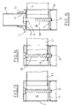
- Figures 13, 14 and 15 are three separate fragmentary, lateral, section views of corresponding possible ways of composition of the modular support structure, proposed by the present invention.
- With reference to the enclosed figures, the reference letter (S) indicates the modular support structure for furniture, proposed by the present invention, as a whole.
- The structure (S), as it appears from Figures 1 and 2, can be formed from a plurality of separate structural elements, which can be reciprocally connected to define a desired spatial configuration, more or less geometrically complicated, of the above pieces of furniture, which can be for example single desks, or workstations including more desks connected to one another, multi-shelves fitting walls, etc.
- After having been composed, the proposed structure (S) forms the supporting frame for the above pieces of furniture: for example, the structure (S) shown in Figures 1 and 2 provides the supporting frame for working surfaces (not shown) of a workstation.
- The above mentioned structural elements of the structure (S), like known modular structures, include a plurality of uprights (M), aimed at assuming a substantially vertical position in the composition of the structure (S), and a plurality of crossbars, indicated in different Figures with (L, L1, L2), aimed at assuming a substantially horizontal configuration and at being connected to the uprights (M) with their ends, to reproduce the spatial configuration desired for the support of the piece of furniture.
- The modular support structure (S) proposed by the present invention differs from known modular structures by the fact that the relevant structural elements can be easily and immediately assembled by rapid mutual connection operations, and by the fact that, after assembling, it is particularly stable and strong.
- This is possible due to the fact that each upright (M) includes (see for example Figure 3) a tubular bar, provided at top with a head (T) designed for multiple connection with the crossbars (L, L1, L2).
- The head (T) defines a vertical hollow (10), which is open at top and whose lateral delimiting walls (12) have removable plates (13), which can be removed to open vertical windows (14) in the walls (12), as it is shown in Figure 12.
- Through the vertical windows (14), end connection portions (22, 23) of corresponding crossbars (L, L1, L2) can enter the hollow (10), to obtain a mutual connection with the upright (M).
- For this purpose, as shown in Figure 3, the vertical hollow (10), whose cross-section corresponds to the one of the upright (M), is closed at bottom by a horizontal base (11), transversal to the same upright (M) and situated at a predetermined level downwards from the upper end of the upright (M).
- The horizontal base (11) is aimed at receiving, resting thereon, the end connection portions (22, 23) of the crossbars (L, L1, L2), coupled with the windows (14) obtained on the lateral walls (12) of the head (T) by removal of the plates (13).
- Moreover, the end connecting portions (22, 23) of the crossbars (L, L1, L2) have the cross-section slightly wider than the width of the windows (14), and they feature, near their ends and on opposite lateral walls, suitable vertical grooves (15), mating with the vertical edges (16) of the windows (14).
- The vertical grooves (15) have width corresponding to the thickness of the vertical edges (16) of the windows (14) and such depth, as to be engaged in stable connection with the edges (16), during coupling between the relative crossbar (L, L1, L2) and the head (T) of an upright (M), in the area of the head window, so as to stabilize the obtained connection configuration.
- In practice, the window (14), obtained in a lateral wall (12) of the head (T) of the upright (M), due to the removal of the plate (13), forms an opening allowing the head (T) of an end connecting portion (22, 23) of a crossbar (L, L1, L2) to be introduces into the hollow (10).
- The vertical edges (16) of the window (14) form both, a kind of guiding track, along which the grooves (15) of the end connecting portion (22, 23) slide during the connection with the upright, and a kind of means for mutual stabilization, after the crossbar and the upright have been connected by setting the lower surface of the end connecting portion (22, 23) onto the base (11) of the hollow (10).
- To ensure a better connection stability between the upright and the crossbar, the bottom edge (17) of the windows (14) has a projection (18) (as shown by way of example in Figure 12) matching in shape with a slot (19) made in the lower surface of the end connecting portion (22, 23) of the crossbars (L, L1, L2) (as it can be seen, for instance, in Figures 8 and 9) designed to go in abutment onto the bottom edge (17) of the window (14) due to the connection of these latter with the head (T) of an upright (M). The projection (18) is inserted into the slot (19) when the mutual connection between the crossbar and the upright is completed.
- According to the embodiment shown as an example in the proposed figures, the head (T) of each upright includes (as shown in detail in Figure 3 and in Figure 12) a single removable plate (13) for each of the delimiting lateral walls (12).
- According to other embodiments, not shown, but included in the scope of the present invention, the head (T) may include a plurality of removable plates (13), for each of the delimiting lateral walls (12).
- This way, a plurality of crossbars (L, L1, L2) can be connected to each lateral wall (12) of the head (T) of an upright (M).
- Consequently, it is possible to connect the same head (T) of a single upright (M), a plurality of crossbars (L, L1, L2) equal in number to the total number of the plates (13), which can be removed from each wall (12) of the head (T).
- For this purpose, taking as reference e.g. the embodiment shown in enclosed figures, according to which the uprights (M) have a square cross-section and each of the four lateral walls (12) delimiting the hollow (10), has only one plate (13), which can be removed to define four vertical windows (14), the dimensions of the base (11) of the hollow (10) of the head (T) are such, as to allow placing the end connecting portions (22, 23) of up to four respective crossbars (L, L1, L2), with each of the end connecting portions (22, 23) being coupled to one of the above mentioned four windows (14).
- It appears clearly from the above description, that the proposed bearing structure (S) can be easily and immediately assembled from a plurality of uprights (M) and a plurality of crossbars (L, L1, L2), which are to be connected to the latter, in order to define various geometrical configurations for supporting pieces of furniture.
- Other characteristic features of the invention are described in the following.
- The crossbars (L, L1, L2) include connection and fastening, first crossbars (L1) and simple connection, second crossbars (L2), for to the head (T) of the uprights (M).
- The connection and fastening, first crossbars (L1) have the vertical grooves (15) at their ends and in the lateral faces, in order to mate with the vertical edges (16) of the windows (14), which are made on the lateral walls (12) of the heads (T).
- Moreover, the connection and fastening, first crossbars (L1) have coaxial through holes (20), made in the lower and upper faces of the end connecting portions (22, 23), between the grooves (15) and the ends.
- The through holes (20) are to be set in coaxial relation with a through hole (21) made in the base (11) of the hollow (10) of the same head (T), due to the connection of the end portions (22) of the first crossbars (L1) with the head (T) of the upright (M), (see Figures 3 and 14), so that mutual fastening means (30), can be introduced therein.
- The second connection crossbars (L2), have only the vertical grooves (15) in the lateral faces of the end connecting portions (23).
- It is enough to couple only one connection and fastening, first crossbar (L1) to the head (T) of each upright, in order to ensure the stability and rigidity of the structure (S) obtained by the connection of the crossbars (L, L1, L2) to the uprights (M).
- For this purpose, as shown in detail in Figures 7, 8, 10 and 11, the end connection portion (22) of said connection and fastening, first crossbars (L1), included between the grooves (15) and the relevant end, and aimed at engaging with the hollow (10) of the head (T) of a corresponding upright (M) for mutual coupling, has an extension (S1) greater than the extension (S2) of the connection portion (23) of said second longitudinal connection bars (L2), which is included between the grooves (15) and the end of the second crossbars (L2).
- This way, the end connection portions (23) of the second crossbars (L2) leave enough space within the hollow (10) for the end connection portions (22) of the first crossbars (L1), as can be seen in Figure 13 in comparison with Figure 14.
- It results to be evident that the proposed structure (S) allows a dramatic reduction of the number of "loose" elements, necessary to connect reciprocally various structural elements composing it.
- In fact, according to the case shown in the Figures, each upright head can be connected contemporarily to four crossbars, from which only one of the first crossbars, and consequently only one "loose" fastening element is used (in the proposed figures indicated with the reference number 30).
- The structure (S) includes also junction elements (N) for the multiple connection of the connection and fastening, first crossbars (L1) and connection, second crossbars (L2). The junction elements (N) may receive in mutual coupling the end connection portions (22, 23) of lined up crossbars so as to join together separate crossbars (L, L1, L2), whose opposite respective end portions (22, 23) are already joined to related uprights (M). The connection way of the junction elements (N) with the crossbars (L, L1, L2) is the same as for the head (T) described hereinabove.
- The use of the junction elements (N), like for example the ones shown in Figures 1 and 2, allows to give to the support structure (S), proposed by the present invention and assembled by the connection between uprights-crossbars-junctions, complicated spatial configurations for supporting pieces of furniture, such as multiple workstations having a plurality of shelves, articulated and connected to one another.
- Similarly to the shape of the heads (T) of the uprights (M), the junction elements (N) include, as shown in Figure 6, tubular sleeves (40), having a base wall (41) and lateral delimiting walls (42), which define an inner vertical hollow (43), aimed at receiving the connection end portions (22, 23) of the crossbars (L, L1, L2), of the first crossbars (L1), as well as of the second crossbars (L2).
- Each of the lateral walls (42) includes at least one plate (44), which can be removed in order to define vertical windows, through which the connection end portions (22, 23) of the crossbars (L, L1, L2), are introduced into the vertical hollow (43).
- The thickness of the vertical edges of the windows corresponds to the width of the vertical grooves (15) made in the crossbars (L, L1, L2).
- The windows of the junction elements (N) form, at the base edge, a projection (45), whose shape matches a slot (19), made in the lower face of the connection end portions (22, 23) of the crossbars (L, L1, L2) which goes in abutment onto the base wall (41) of the junction (N) for connection with the relative crossbar.
- The slot (19) is aimed at engaging with the projection (45), after the connection has been completed.
- Advantageously, the outline (C) of the plates (13), which can be removed from the lateral walls (12) of the heads (T) of the uprights (M), is made by cutting the lateral wall. By this cutting, vertical edges (16), the base edge (17), the projection (18), and breaking points (50) are defined along the above mentioned outline (C).
- Thus, the removal of the plates (13) is immediate by a simple and weak stress, for example rotation of the plates around the breaking points (50) during connection with a crossbar (L, L1, L2).
- In the same way, the outline of the plates (44), which can be removed from the lateral walls (42) of the structural junction elements (N), is made by cutting the lateral walls. By this cutting, vertical edges, the base edge, the projection (45), and the breaking points are defined along the above mentioned outline.
- Consequently, also in this case, the removal of the plates (44) is immediate by a simple and weak stress, for example by rotation of the plates around the breaking points during the connection with a crossbar (L, L1, L2).
- In order to obtain complicated multi-level geometrical configurations for pieces of furniture, the proposed support modular structure (S) includes other vertical extension structural elements (70), which, as shown in Figure 15, include tubular section bars, whose cross-section is similar to and smaller than the cross-section of the uprights (M).
- The lower end (71) of the vertical extension structural elements (70) is coupled to the upper end of the head (T) of the uprights (M).
- For this purpose, the lower ends (71) of the vertical extension structural elements (70) have base plates (72), whose shape is complementary to the hollows (10) of the heads (T) and which are aimed at being introduced into the latter, in abutment against the upper face of the crossbars (L, L1, L2), connected thereto.
- The vertical extension structural elements (70) include also stabilizing collars (73), which are fitted on the vertical extension structural elements (70) and are set in abutment against the upper end of the heads (T) of the uprights (M), to stabilize the connection between the vertical extension element and the upright.
- Like the uprights (M), also the vertical extension structural elements (70) have heads (not shown in Figures), featuring vertical hollows and delimited by lateral walls, in which removable plates are cut in order to define windows, after removal thereof, through which the end connection portions of the crossbars are introduced.
- The vertical extension structural element (70) is connected to the upright (M) below by means of through holes (74), made in the base plates (72) and coaxial, after the coupling with heads (T) of the uprights (M), with holes (21) made in the base (11) of the hollows (10) of the heads (T), in order to allow introduction of suitable mutual fastening means (90).
- According to a possible embodiment, not shown, the vertical extension structural elements (70) can be coupled, in their upper part, with the above mentioned junction structural elements (N).
- The modular support structure (S), proposed by the present invention, is not only easy to assemble, from various structural elements, which can be assembled together by simple and rapid operations, and requires the use of an extremely reduced number of "loose" elements, but it is also extremely versatile, thus allowing to obtain complicated and multi-level configurations.
- In fact, although according to the embodiment shown in the proposed figures, the uprights (M), the vertical extension elements (70) and the junction elements (N) have a square cross-section, it is possible to obtain various geometrical configurations for supporting workstations or fitting walls, using, at the same time or alternatively, uprights (M), vertical extension elements (70) and junction elements (N) having respectively triangular, rectangular or polygonal cross-section.
Claims (21)
- Modular support structure for pieces of furniture, which can be assembled from a plurality of separate and different structural elements, which can be connected with one another and include a plurality of uprights (M) and a plurality of crossbars (L, L1, L2), which are to be connected, at the relative ends, with said uprights (M), in order to form a desired spatial configuration of said articles, wherein each of the uprights (M) is formed by a tubular section bar with a head (T) at top for multiple connection with said crossbars (L, L1, L2), the head delimiting a vertical hollow (10), open at top and having lateral delimiting walls (12), with each of said walls (12) featuring at least one removable plate (13), which can be removed to open, in said wall (12), a vertical window (14), through which an end connection portion (22, 23) of a crossbar of said crossbars (L, L1, L2) is introduced; characterised in that said end portions (22, 23) have cross-sections slightly bigger than the width of the windows (14) and featuring, near their ends and in their lateral surfaces, grooves (15) with a width corresponding to the thickness of the vertical edges (16) of said window (14) and a depth such that they engage with the edges (16) during the coupling between the crossbar (L, L1, L2) and the head (T) of the upright (M), so as to obtain a mutual connection between the crossbar (L, L1, L2) and the head (T) of the upright (M).
- Structure according to claim 1, characterized in that said windows (14) form, at the base edge (17), a projection (18) matching in shape a slot (19) made in the lower face of the end connection portions (22, 23) of said crossbars (L, L1, L2) which is set in abutment against said base edge (17) of said window (14) during the connection of the crossbars (L, L1, L2) with the hollow (10) of a respective upright (M), with said slot (19) being aimed at engaging with said projection (18), after said connection has been completed.
- Structure according to claim 2, characterized in that said hollow (10) has a horizontal base (11), internal and transversal to the upright (M) and situated at a below the upper end of the latter, at a height corresponding to the base edge (17) of said window (14) receiving in abutment on a partial portion of the same base facing the same window (14), a corresponding end connection portion (22, 23) of said crossbars (L, L1, L2).
- Structure according to claim 1, characterized in that said head (T) includes, for each one of the lateral delimiting walls (12), a plurality of removable plates (13), aimed at receiving, in mutual connection, a corresponding plurality of crossbars (L, L1, L2).
- Structure according to claim 4, characterized in that a number of crossbars (L, L1, L2) equal to the total number of plates (13) removable from each wall (12) of said head (T), can be connected to the head (T) of a single upright (M).
- Structure according to claim 3, characterized in that said crossbars (L, L1, L2) include connection and fastening, first crossbars (L1), which have said grooves (15), made near their ends and in their lateral surfaces, for connection with the vertical edges (16) of said windows (14), and which have coaxial through holes (20), made in the lower and upper surfaces of the end connection portions (22), between said grooves (15) and the ends of said crossbars (L1), said through holes (20) being set in coaxial relation with at least one through hole (21) made in the base (11) of the hollow (10) of the head (T), when said first crossbars (L1) are connected with a head (T) of a relative upright (M), in order to allow the introduction of mutual fastening means (30), said crossbars (L, L1, L2) including also connection, second connection crossbars (L2), which have at their ends and in their lateral surfaces, only the above mentioned grooves (15) for mutual coupling with the vertical edges (16) of said windows (14).
- Structure according to claim 6, characterized in that the end connection portion (22) of said connection and fastening, first crossbars (L1), included between the grooves (15) and the relevant end, and aimed at engaging with the hollow (10) of the head (T) of a corresponding upright (M) for mutual coupling, has an extension (S1) greater than the extension (S2) of the connection portion (23) of said connection second crossbars (L2), which is included between the grooves (15) and the end of the second crossbars (L2).
- Structure according to claim 7, characterized in that it includes a plurality of said connecting, second crossbars (L2) and at least one of said connecting and fastening, first crossbars (L1), mutually coupled and connected to corresponding windows (14) of the same multiple connection head (T) of only one upright (M).
- Structure according to claim 1 and claim 6,
characterized in that it includes also junction structural elements (N) for multiple connection of said longitudinal connecting and fastening first bars (L1) and said connecting, second crossbars (L2), aimed at receiving in mutual coupling the end connection portions (22, 23) of the latter and at joining separate crossbars (L, L1, L2), already joined with their remaining end portions (22, 23) to respective uprights (M), to define complicated spatial configurations for supporting said pieces of furniture. - Structure according to claim 9, characterized in that said junction structural elements (N) include tubular sleeves (40) having a base wall (41) and lateral walls (42) delimiting and defining an internal vertical hollow (43), aimed at being occupied by the end connection portions (22, 23) of said crossbars (L, L1, L2), connection and fastening, first crossbars (L1) and connection, second crossbars (L2), with each of said lateral walls (42) including at least one removable plate (44), which can be removed to define windows for allowing the introduction of said end connection portions (22, 23) of said crossbars (L, L1, L2) into said vertical hollow (43), with the thickness of the vertical edges of the windows corresponding to the width of the grooves (15) made in the crossbars (L, L1, L2).
- Structure according to claim 10, characterized in that the windows of said junction structural elements (N) form, near the base edge, a projection (45), whose shape is complementary to a slot (19) made in the lower surface of the end connection portions (22, 23) of said crossbars (L, L1, L2) which goes in abutment against the base wall (41) of the junction (N) in mutual coupling with the relevant crossbar, with said slot (19) being aimed at engaging with said projection (45), after said mutual coupling has been completed.
- Structure, according to claim 1 and claim 2, characterized in that the outline (C) of the plates (13) which can be removed from the lateral walls (12) of the heads (T) of said uprights (M) is obtained by cutting each lateral wall of the heads, by which cutting, vertical edges (16), the base edge (17), the projection (18), and breaking points (50) for removal of the plate, are defined along each above mentioned outline (C).
- Structure according to claim 10, characterized in that the outline of the plates (44),which can be removed from the lateral walls (42) to delimit said junction elements (N) is obtained by cutting each lateral wall of the junction element, by which cutting, vertical edges, the base edge, the projection (45), and breaking points for removal of the plate, are defined along each above mentioned outline (C).
- Structure according to claim 1, characterized in that it includes vertical extension structural elements (70), formed by tubular section bars, whose cross-section is similar to and smaller than the cross-section of said uprights (M), and which are connected at the lower end (71) with the upper end of the head (T) of said uprights (M), to obtain a multi-level configuration for supporting said pieces of furniture.
- Structure according to claim 14, characterized in that the lower ends (71) of said vertical extension structural elements (70) have base plates (72), whose shape is complementary to the hollows (10) of said heads (T) and which are introduced into the latter, in abutment against the upper face of the crossbars (L, L1, L2), connected thereto, with said vertical extension structural elements (70) including stabilizing collars (73), which are fitted on the vertical extension structural elements (70) and set in abutment against the upper end of the heads (T) of the uprights (M).
- Structure according to claim 15, characterized in that said base plates (72) have through holes (74) arranged in coaxial relation, after the connection with the heads (T) of the uprights (M), with holes (21) made in the base (11) of the hollows (10) of the heads (T), in order to allow the introduction of suitable mutual fastening means (90).
- Structure according to claim 10 and claim 14, characterized in that said vertical extension structural elements (70) can be connected, at top, with said junction elements (N).
- Structure according to claim 1, characterized in that the cross-section of said uprights (M), said vertical extension structural elements (70) and said junction structural elements (N) is triangular.
- Structure according to claim 1, characterized in that the cross-section of said uprights (M), said vertical extension structural elements (70) and said junction structural elements (N) is squared.
- Structure according to claim 1, characterized in that the cross-section of said uprights (M), said vertical extension structural elements (70) and said junction structural elements (N) is rectangular.
- Structure according to claim 1, characterized in that the cross-section of said uprights (M), said vertical extension structural elements (70) and said junction structural elements (N) is polygonal.
Applications Claiming Priority (2)
| Application Number | Priority Date | Filing Date | Title |
|---|---|---|---|
| ITBO20030189 ITBO20030189A1 (en) | 2003-04-02 | 2003-04-02 | MODULAR SUPPORTING STRUCTURE FOR FURNITURE ITEMS |
| ITBO20030189 | 2003-04-02 |
Publications (2)
| Publication Number | Publication Date |
|---|---|
| EP1464251A1 EP1464251A1 (en) | 2004-10-06 |
| EP1464251B1 true EP1464251B1 (en) | 2006-06-21 |
Family
ID=32843883
Family Applications (1)
| Application Number | Title | Priority Date | Filing Date |
|---|---|---|---|
| EP20040007505 Expired - Lifetime EP1464251B1 (en) | 2003-04-02 | 2004-03-29 | Modular support structure for furniture |
Country Status (4)
| Country | Link |
|---|---|
| EP (1) | EP1464251B1 (en) |
| DE (1) | DE602004001257D1 (en) |
| ES (1) | ES2268523T3 (en) |
| IT (1) | ITBO20030189A1 (en) |
Families Citing this family (2)
| Publication number | Priority date | Publication date | Assignee | Title |
|---|---|---|---|---|
| KR200492741Y1 (en) * | 2019-06-25 | 2020-12-03 | 정순철 | Prefabricated table |
| CN112027378A (en) * | 2020-08-20 | 2020-12-04 | 中远海运特种运输股份有限公司 | Combined frame box |
Family Cites Families (4)
| Publication number | Priority date | Publication date | Assignee | Title |
|---|---|---|---|---|
| US3887288A (en) * | 1974-01-08 | 1975-06-03 | James Daivd Inc | Corner construction |
| AT337931B (en) * | 1975-02-18 | 1977-07-25 | Vieler Gmbh Geb | FRAME FOR SHELVES AND DGL. |
| DE4142953C2 (en) * | 1991-12-24 | 1994-03-17 | Heinrich Oelschlaeger Metallwa | Corner connection section on hollow profiles |
| FR2753241B1 (en) * | 1996-09-11 | 1998-12-04 | Hazan Jacques | NEW ASSEMBLY FOR MODULAR FURNITURE ELEMENTS AND FURNITURE THUS FORMED |
-
2003
- 2003-04-02 IT ITBO20030189 patent/ITBO20030189A1/en unknown
-
2004
- 2004-03-29 EP EP20040007505 patent/EP1464251B1/en not_active Expired - Lifetime
- 2004-03-29 DE DE200460001257 patent/DE602004001257D1/en not_active Expired - Lifetime
- 2004-03-29 ES ES04007505T patent/ES2268523T3/en not_active Expired - Lifetime
Also Published As
| Publication number | Publication date |
|---|---|
| DE602004001257D1 (en) | 2006-08-03 |
| EP1464251A1 (en) | 2004-10-06 |
| ITBO20030189A1 (en) | 2004-10-03 |
| ES2268523T3 (en) | 2007-03-16 |
Similar Documents
| Publication | Publication Date | Title |
|---|---|---|
| US5158187A (en) | Tray of shelf-like structure | |
| US6681705B2 (en) | Support structure and method of assembly thereof | |
| US6701678B1 (en) | Modular storage enclosure | |
| US5466058A (en) | Stackable interlocking modular storage system | |
| US4621381A (en) | Knockdown sofa | |
| US5813737A (en) | Construction system | |
| US20050200250A1 (en) | Modular furniture | |
| CA2601142A1 (en) | Modular furniture | |
| US5348170A (en) | Free-standing shelving system | |
| KR102075150B1 (en) | Non-bolt prefabricated angle frame structure and angle frame assembly using the same | |
| US4880284A (en) | Chest of drawers and method of assembly | |
| KR20200128425A (en) | Furniture system | |
| US20060243177A1 (en) | Bookcase with sloping shelves | |
| US5127341A (en) | Assemblable carcase | |
| US20160262541A1 (en) | Channel tube and tube nut framing apparatus | |
| EP1464251A1 (en) | Modular support structure for furniture | |
| US6039191A (en) | Kitchen rack | |
| EP0063396B1 (en) | Structural elements for realizing modular furniture | |
| DK153282B (en) | SKETCH, ISAAR FOR A FURNITURE | |
| US4356777A (en) | Knockdown structure | |
| CN110107568B (en) | Assembled self-locking frame | |
| WO2006132499A1 (en) | Structure of knocked down furniture | |
| CA3099472A1 (en) | Wall hanging system | |
| KR880004492Y1 (en) | Connecting member for assembling the board by connecting up, down, left and right | |
| KR102750016B1 (en) | Assembly furniture |
Legal Events
| Date | Code | Title | Description |
|---|---|---|---|
| PUAI | Public reference made under article 153(3) epc to a published international application that has entered the european phase |
Free format text: ORIGINAL CODE: 0009012 |
|
| AK | Designated contracting states |
Kind code of ref document: A1 Designated state(s): AT BE BG CH CY CZ DE DK EE ES FI FR GB GR HU IE IT LI LU MC NL PL PT RO SE SI SK TR |
|
| AX | Request for extension of the european patent |
Extension state: AL LT LV MK |
|
| 17P | Request for examination filed |
Effective date: 20050406 |
|
| GRAP | Despatch of communication of intention to grant a patent |
Free format text: ORIGINAL CODE: EPIDOSNIGR1 |
|
| AKX | Designation fees paid |
Designated state(s): DE ES GB |
|
| RBV | Designated contracting states (corrected) |
Designated state(s): DE ES GB |
|
| GRAS | Grant fee paid |
Free format text: ORIGINAL CODE: EPIDOSNIGR3 |
|
| GRAA | (expected) grant |
Free format text: ORIGINAL CODE: 0009210 |
|
| AK | Designated contracting states |
Kind code of ref document: B1 Designated state(s): DE ES GB |
|
| REG | Reference to a national code |
Ref country code: GB Ref legal event code: FG4D |
|
| REF | Corresponds to: |
Ref document number: 602004001257 Country of ref document: DE Date of ref document: 20060803 Kind code of ref document: P |
|
| PG25 | Lapsed in a contracting state [announced via postgrant information from national office to epo] |
Ref country code: DE Free format text: LAPSE BECAUSE OF FAILURE TO SUBMIT A TRANSLATION OF THE DESCRIPTION OR TO PAY THE FEE WITHIN THE PRESCRIBED TIME-LIMIT Effective date: 20060922 |
|
| REG | Reference to a national code |
Ref country code: ES Ref legal event code: FG2A Ref document number: 2268523 Country of ref document: ES Kind code of ref document: T3 |
|
| PLBE | No opposition filed within time limit |
Free format text: ORIGINAL CODE: 0009261 |
|
| STAA | Information on the status of an ep patent application or granted ep patent |
Free format text: STATUS: NO OPPOSITION FILED WITHIN TIME LIMIT |
|
| 26N | No opposition filed |
Effective date: 20070322 |
|
| PGFP | Annual fee paid to national office [announced via postgrant information from national office to epo] |
Ref country code: GB Payment date: 20100319 Year of fee payment: 7 |
|
| PGFP | Annual fee paid to national office [announced via postgrant information from national office to epo] |
Ref country code: ES Payment date: 20100319 Year of fee payment: 7 |
|
| GBPC | Gb: european patent ceased through non-payment of renewal fee |
Effective date: 20110329 |
|
| PG25 | Lapsed in a contracting state [announced via postgrant information from national office to epo] |
Ref country code: GB Free format text: LAPSE BECAUSE OF NON-PAYMENT OF DUE FEES Effective date: 20110329 |
|
| REG | Reference to a national code |
Ref country code: ES Ref legal event code: FD2A Effective date: 20120424 |
|
| PG25 | Lapsed in a contracting state [announced via postgrant information from national office to epo] |
Ref country code: ES Free format text: LAPSE BECAUSE OF NON-PAYMENT OF DUE FEES Effective date: 20110330 |