EP1464215B2 - Machine for mowing of stalk-like crop - Google Patents
Machine for mowing of stalk-like crop Download PDFInfo
- Publication number
- EP1464215B2 EP1464215B2 EP03027603A EP03027603A EP1464215B2 EP 1464215 B2 EP1464215 B2 EP 1464215B2 EP 03027603 A EP03027603 A EP 03027603A EP 03027603 A EP03027603 A EP 03027603A EP 1464215 B2 EP1464215 B2 EP 1464215B2
- Authority
- EP
- European Patent Office
- Prior art keywords
- conveyor
- mowing
- machine
- crop
- transverse
- Prior art date
- Legal status (The legal status is an assumption and is not a legal conclusion. Google has not performed a legal analysis and makes no representation as to the accuracy of the status listed.)
- Expired - Lifetime
Links
- 241000196324 Embryophyta Species 0.000 description 36
- 238000003306 harvesting Methods 0.000 description 8
- 230000000694 effects Effects 0.000 description 5
- 240000008042 Zea mays Species 0.000 description 3
- 235000002017 Zea mays subsp mays Nutrition 0.000 description 3
- 230000005484 gravity Effects 0.000 description 3
- 239000000463 material Substances 0.000 description 3
- 235000016383 Zea mays subsp huehuetenangensis Nutrition 0.000 description 2
- 239000000969 carrier Substances 0.000 description 2
- 235000013399 edible fruits Nutrition 0.000 description 2
- 239000004459 forage Substances 0.000 description 2
- 235000009973 maize Nutrition 0.000 description 2
- 230000002940 repellent Effects 0.000 description 2
- 239000005871 repellent Substances 0.000 description 2
- 235000005824 Zea mays ssp. parviglumis Nutrition 0.000 description 1
- 235000005822 corn Nutrition 0.000 description 1
- 230000008878 coupling Effects 0.000 description 1
- 238000010168 coupling process Methods 0.000 description 1
- 238000005859 coupling reaction Methods 0.000 description 1
- 239000004460 silage Substances 0.000 description 1
- 238000011144 upstream manufacturing Methods 0.000 description 1
- 238000004804 winding Methods 0.000 description 1
Images

Classifications
-
- A—HUMAN NECESSITIES
- A01—AGRICULTURE; FORESTRY; ANIMAL HUSBANDRY; HUNTING; TRAPPING; FISHING
- A01D—HARVESTING; MOWING
- A01D43/00—Mowers combined with apparatus performing additional operations while mowing
- A01D43/08—Mowers combined with apparatus performing additional operations while mowing with means for cutting up the mown crop, e.g. forage harvesters
- A01D43/081—Mowers combined with apparatus performing additional operations while mowing with means for cutting up the mown crop, e.g. forage harvesters specially adapted for ensilage of maize
- A01D43/082—Gathering units
Definitions
- the invention relates to a machine for mowing stalk-like crop, with juxtaposed in front of a feeder channel collection and Mäh experienceden for cutting and conveying the crop, transverse conveyor for transverse promotion of crops cut at least approximately transversely to the forward direction to the center of the machine, Umlenk Stammkarn that of the Feed cross-conveyor incoming crop to a feeder channel through which the crop of a chaffing device is inclusionbbar, and with an approximately vertical axis rotatably driven conveyors at the top of the Umlenkwanschn adjacent collection and Mäh listeningen comprising a conveyor disc and drivingly permanently with the feeder and Mowing directions are coupled.
- the EP 1 177 718 A proposes to solve this problem, above and in the forward direction in front of the transverse conveyor channel to arrange a rotatably driven conveyor, which promotes the emerged from the transverse conveyor channel plants back into the latter.
- the conveyor is rotated about a preferably horizontal, transverse to the direction of rotation axis. Their speed must therefore be enough to bring the plant back into the cross conveyor channel. Since the plants come to lie on the conveyor, the conveying effect of the conveyor based only on gravity, which may not be sufficient in some cases, since the conveyor slides on the plant.
- the EP 0 504 639 A describes a maize harvesting machine in which the intake and mowing devices consist of a disk-shaped knife carrier with knives and conveyor drums attached thereto.
- the conveyor drums can consist of a frusto-conical base body, are firmly connected to the horizontal driving surfaces and an overlying cylindrical conveying roller. Two adjacent conveyor drums move the cut corn stalks towards a cross auger.
- the problem underlying the invention is seen to improve the Gut constitutive in a machine for mowing stalk-like crop, especially when only part of the mowing and catch drums is acted upon by plant material or relatively ripe crop is harvested.
- a machine for mowing stalk-like crops comprises intake and mowing devices arranged side by side in front of a feeder channel.
- the conveyors are arranged above the intake and mowing devices which are adjacent to the Umlenk bekarn. They are thus on both sides in the direction of travel in front of the feed chute leading to the chopper and are drivingly coupled permanently with the collection and mowing.
- the conveyors are each provided with a vertical or at least approximately vertical axis of rotation. The direction of rotation is so selected that from the cross conveyor leaked plants or parts are reintroduced into the Erntegutstrom.
- the conveyor is composed of a flat, preferably provided with upwardly projecting drivers conveyor disc and a coaxially arranged above the conveyor disc, smooth or equipped with carriers conveyor drum together.
- the inventive choice of the shape of the conveyor allows a powerful and active promotion of plants, since the conveying effect is not limited by the weight of the plants.
- the drivers can be rigidly attached to the conveyor disc or conveyor drum, although controlled drivers are conceivable.
- the drivers can thus depending on their respective angular position more or less far outwardly from the conveyor disc or conveyor drum survive, such as fingers on screw conveyors of cutting units, and / or are pivoted, such as the tines of a reel of a cutting unit.
- the drivers are rigid and curved against the direction of rotation trailing to give them a repellent conveying behavior.
- the collection and mowing devices can be constructed of disks arranged one above the other with recesses distributed around their circumference for receiving plant stems and mower disks arranged thereunder. Then the conveyors are at least on the collection and mowing facilities, which are upstream of the intake channel. However, the collection and mowing facilities may also include a provided with holding means for the mowed crop link chain having a working strand side, which is movable in use transverse to the direction of travel of the machine. Then the conveyors are located at the inner end portions of the Link chains. It would also be conceivable to allocate one or more conveyors further on the outside to the transverse conveyors.
- the conveyor is automatically reversed, so that it can support the removal of jammed material from the feeder channel.
- the conveyor is particularly advantageous because it also promotes the out of the feeder channel when reversing out promoted crop following the reversing in the feeder channel.
- a plate also referred to as the center table, which is arranged above the middle two drawing-in and mowing devices. Since the conveying element according to the invention is positioned exactly where the Erntegutabl was stored, its conveying effect comes very well to the effect, without resulting in unnecessary friction losses.
- the conveyor is driven by rotation.
- it can be connected via a shaft and optionally by a gear with an adjacent feeding and mowing device, which is also set in rotation by a drive.
- FIG. 1 a machine 10 according to the invention for mowing stalk-like crop is reproduced.
- eight feed and mowing devices 14 are laterally juxtaposed, which consist in a conventional manner of coaxial with associated mower discs arranged conveyor discs with a plurality of distributed over the circumference pocket-shaped recesses.
- the conveyor discs capture and transport the stem-like crop that is cut off from the bottom of the field by means of the mower discs.
- the number of intake and delivery devices 14 of the machine 10 is arbitrary, so it can more or less than those in FIG. 1 shown eight intake and conveying 14 find use.
- the crop is removed from the conveyors by excavators (which are not shown in the drawings for reasons of clarity) that may be designed as rotating discs or fixed elements, and through the infeed and mowing devices 14 cooperating transverse conveyor drums 16, which are provided with projecting driver teeth which penetrate corresponding slots in the rear wall of the machine 10, conveyed in the lateral direction to the center of the machine 10.
- the intake duct 18 of a forage harvester is arranged.
- the crop is in the middle of the machine 10 by both sides in the forward direction of the intake duct 18 arranged inclined conveyor drums 20, which are also provided with driving teeth, fed into the intake duct 18.
- the axes of rotation of the inclined conveyor drums 20 are inclined forward.
- the collection and mowing devices 14 are driven by approximately vertical, or slightly inclined forward axes of rotation.
- the transverse conveyor drums 16 and the inclined conveyor drums 20 are rotated.
- the corresponding drive is made by a self-propelled harvester, usually a forage harvester, the feed channel 18 is arranged at the rear of the center of the machine and the machine in the forward direction moved across a field.
- the machine 10 is releasably secured to the self-propelled harvester by a support frame 28.
- the directions of rotation of the intake and mowing devices 14 are opposite directions on both sides of the longitudinal center plane of the machine 10, wherein the respective inner three intake and mowing devices 14 rotate in opposite directions to the respective outermost intake and mowing devices 14.
- the plants standing there 24 are optionally pushed sideways to the side by stalk dividers 22, detected by the row-independent pulling and mowing devices 14 and separated from the ground.
- the plants 24 are then transported transversely to the forward direction of travel in the transverse conveying channel 26 defined between the rear wall of the machine 10 and the transverse conveyor drums 16 on the one hand and the infeed and mowing means 14 on the other hand by the transverse conveyors to the center of the machine 10. There they are conveyed by serving as Umlenkromeffen inclined conveyor drums 20 in the feed channel 18.
- the configuration of the transverse conveyor channel 26 is arbitrary within the scope of the inventive concept. It can be like in the FIG. 1 to act a formed between the rear wall of the machine 10 and the front arranged feed and mowing 14 channel through which the good is transported by the intake and mowing device 14 in cooperation with behind arranged transverse conveyor drums 16 or with driven Ausipporusionn or cross conveyor belts ( DE 195 27 607 A . DE 195 31 918 A and DE 198 56 444 A ).
- An independent of the collection and mowing 14 transport of the crop in the transverse conveyor channel 26 is conceivable that by separate conveyor, for example in the form of conveyor belts or augers ( GB 2 012 154 A ) can be accomplished.
- two conveyors 32 are arranged above the middle table 30 at the top of the two middle intake and mowing devices 14.
- the axis of rotation of the conveyors 32 extend approximately vertically and are, like those of the collection and mowing devices 14, slightly inclined forward.
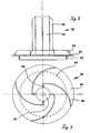
- the conveyors 32 sit down - as based on the FIGS. 2 and 3 can be seen more accurately - from a lower circular conveyor disc 34 and a coaxial with the conveyor disc 34 disposed above the cylindrical conveying drum 36 together.
- the conveyor disc 34 is provided with upwardly projecting, curved drivers 38. The curvature of the driver 38 runs counter to the direction of rotation, so that there is a repellent conveying behavior.
- the top of the driver 38 could be equipped to enhance the aggressiveness still with triangular or saw-toothed elevations.
- the conveyor drum 36 is also provided with drivers 40, which are, however, radially oriented.
- At the bottom of the conveyor disc 34 is a downwardly extending cylindrical collar 42 is mounted as a winding protection.
- the conveyors 32 are arranged coaxially with the respectively arranged thereunder collection and Mäh wornen. They are each connected by a shaft and optionally by a gear drive with the arranged below them collection and mowing device 14.
- the conveyors 32 promote plants 24 ', which have come out of the transverse conveyor channel 26, or of the plants during the deflection in the intake duct 18 falling fruit levels, automatically back into the transverse conveyor channel 26, since their the plants 24' the worn surfaces facing in the normal Harvesting operation in the direction of the intake channel 18 to rotate, as in FIG. 1 indicated by the arrows. Thereafter, the plants are conveyed by the inclined conveyor drums 20 in the intake duct 18.
- the chosen direction of rotation and positioning of the conveyors 32 have the advantage that the plants are promoted aggressively and effectively.
- the conveyors 32 are driven in reverse operation of the machine 10 in the reverse direction. They support the drop when reversing from the intake duct 18 ejected crop on the two outer sides of the center table 30. If the normal harvesting operation is resumed after reversing, promote the stored crop there again in the transverse conveyor channel 26, from which it in the feeder channel 18 arrived. If the crop is to be deposited on the center of the center table 30 during reversing, the direction of rotation of the conveyors 32 selected during the harvesting operation can also be maintained during reversing and reversed briefly prior to the resumption of the harvesting operation in order to remove the plants from the center table 30.
Landscapes
- Life Sciences & Earth Sciences (AREA)
- Environmental Sciences (AREA)
- Harvester Elements (AREA)
- Harvesting Machines For Specific Crops (AREA)
Abstract
Description
Die Erfindung betrifft eine Maschine zum Mähen von stängelartigem Erntegut, mit nebeneinander vor einem Einzugskanal angeordneten Einzugs- und Mäheinrichtungen zum Abschneiden und Fördern des Ernteguts, Querfördermitteln zur Querförderung des abgeschnittenen Ernteguts zumindest näherungsweise quer zur Vorwärtsfahrtrichtung zur Mitte der Maschine, Umlenkfördermitteln, die das von den Querfördermitteln einlaufende Erntegut einem Einzugskanal zuführen, durch den das Erntegut einer Häckseleinrichtung aufgebbar ist, und mit um eine etwa vertikale Achse drehbar antreibbaren Fördereinrichtungen an der Oberseite der den Umlenkfördermitteln benachbarten Einzugs- und Mäheinrichtungen, die eine Förderscheibe umfassen und antriebsmäßig permanent mit den Einzugs- und Mäheinrichtungen gekoppelt sind.The invention relates to a machine for mowing stalk-like crop, with juxtaposed in front of a feeder channel collection and Mäheinrichtungen for cutting and conveying the crop, transverse conveyor for transverse promotion of crops cut at least approximately transversely to the forward direction to the center of the machine, Umlenkfördermitteln that of the Feed cross-conveyor incoming crop to a feeder channel through which the crop of a chaffing device is aufgebbar, and with an approximately vertical axis rotatably driven conveyors at the top of the Umlenkfördermitteln adjacent collection and Mäheinrichtungen comprising a conveyor disc and drivingly permanently with the feeder and Mowing directions are coupled.
Es kommt gelegentlich vor, dass bei der Ernte von stängelartigem Erntegut - beispielsweise von Silomais - am Rand eines Feldes nur eine oder zwei Pflanzenreihen stehen bleiben. Diese Pflanzenreihen können nur mit den äußeren Mäh- und Einzugseinrichtungen der Maschine geschnitten und eingezogen werden. Bei einer sehr breiten Maschine (z. B. einer 8 oder 10 Pflanzenreihen erfassenden Ausführungsform) müssen die Pflanzen über einen längeren Weg durch die Querfördermittel zur Mitte der Maschine transportiert werden. Da an den mittleren Mäh- und Einzugseinrichtungen keine weiteren Pflanzen einlaufen, werden die geschnittenen Pflanzen nicht durch in die Querfördermittel einlaufendes Material in den Querfördermitteln gehalten, sondern stehen relativ lose darin. Durch einen hohen Schwerpunkt bedingt, können sich die Pflanzen beim Transport immer weiter nach unten neigen und rutschen dann mit ihren unteren Enden aus den Querfördermitteln heraus.It sometimes happens that when harvesting stem-like crops - for example silage maize - only one or two rows of plants stop at the edge of a field. These rows of plants can only be cut and pulled in with the machine's external mowing and drawing facilities. In a very wide machine (e.g., an 8 or 10 plant row engaging embodiment), the plants must be transported over a longer distance through the cross conveyors to the center of the machine. Since no further plants enter the middle mowing and intake devices, the cut plants are not held in the transverse conveying means by material entering the transverse conveying means, but are relatively loose therein. Due to a high center of gravity, the plants can always tilt downwards during transport and then slide with their lower ends out of the transverse conveyors.
Seitlich vor dem Einzugskanal sind bei einer Ausführungsform gemäß
Die
Die
Ein anderes Problem bei bekannten Maschinen zur Ernte von stängelartigem Erntegut besteht darin, dass bei der Umlenkung des Ernteguts von der Querförderung nach hinten in den Einzugskanal, die durch aktive oder passive Umlenkfördermittel bewerkstelligt wird, relativ starke Trägheitskräfte auf die Pflanzen wirken. Diese Trägheitskräfte können bei sehr reifem Erntegut dazu führen, dass sich Fruchtstände von den Pflanzen lösen, auf den Erdboden fallen und so dem Ernteprozess verloren gehen.Another problem with known machines for harvesting stalk-like crops is that during the deflection of the Crops from the transverse promotion back into the intake channel, which is accomplished by active or passive deflection conveyors, relatively strong inertial forces act on the plants. These inertial forces can cause fruit to break loose from the plants, fall to the ground and be lost to the harvesting process.
Zur Lösung dieses Problems wird in der
Das der Erfindung zu Grunde liegende Problem wird darin gesehen, die Gutförderung in einer Maschinen zum Mähen von stängelartigem Erntegut zu verbessern, insbesondere wenn nur ein Teil der Mäh- und Einzugstrommeln mit Pflanzenmaterial beaufschlagt wird oder relativ reifes Erntegut geerntet wird.The problem underlying the invention is seen to improve the Gutförderung in a machine for mowing stalk-like crop, especially when only part of the mowing and catch drums is acted upon by plant material or relatively ripe crop is harvested.
Dieses Problem wird erfindungsgemäß durch die Lehre des Patentanspruchs 1 gelöst, wobei in den weiteren Patentansprüchen Merkmale aufgeführt sind, die die Lösung in vorteilhafter Weise weiterentwickeln.This problem is inventively solved by the teaching of claim 1, wherein in the other claims features are listed, which further develop the solution in an advantageous manner.
Eine Maschine zum Mähen von stängelartigem Erntegut umfasst nebeneinander vor einem Einzugskanal angeordnete Einzugs- und Mäheinrichtungen. Die Fördereinrichtungen sind oberhalb der Einzugs- und Mäheinrichtungen angeordnet, die den Umlenkfördermitteln benachbart sind. Sie befinden sich somit auf beiden Seiten in Fahrtrichtung vor dem zur Häckseleinrichtung führenden Einzugskanal und sind antriebsmäßig permanent mit den Einzugs- und Mäheinrichtungen gekoppelt. Die Fördereinrichtungen sind jeweils mit einer vertikalen oder zumindest näherungsweise vertikalen Drehachse versehen. Die Drehrichtung wird derart gewählt, dass aus den Querfördermitteln ausgetretene Pflanzen bzw. -teile wieder in den Erntegutstrom eingebracht werden. Die Fördereinrichtung setzt sich aus einer flachen, vorzugsweise mit nach oben überstehenden Mitnehmern ausgestattete Förderscheibe und einer koaxial über der Förderscheibe angeordneten, glatten oder mit Mitnehmern ausgestatteten Fördertrommel zusammen.A machine for mowing stalk-like crops comprises intake and mowing devices arranged side by side in front of a feeder channel. The conveyors are arranged above the intake and mowing devices which are adjacent to the Umlenkfördermitteln. They are thus on both sides in the direction of travel in front of the feed chute leading to the chopper and are drivingly coupled permanently with the collection and mowing. The conveyors are each provided with a vertical or at least approximately vertical axis of rotation. The direction of rotation is so selected that from the cross conveyor leaked plants or parts are reintroduced into the Erntegutstrom. The conveyor is composed of a flat, preferably provided with upwardly projecting drivers conveyor disc and a coaxially arranged above the conveyor disc, smooth or equipped with carriers conveyor drum together.
Die erfindungsgemäße Wahl der Form der Fördereinrichtung ermöglicht eine kraftvolle und aktive Förderung der Pflanzen, da die Förderwirkung nicht durch die Gewichtskraft der Pflanzen begrenzt ist.The inventive choice of the shape of the conveyor allows a powerful and active promotion of plants, since the conveying effect is not limited by the weight of the plants.
Die Mitnehmer können starr an der Förderscheibe oder Fördertrommel angebracht sein, obwohl auch gesteuerte Mitnehmer denkbar sind. Die Mitnehmer können somit in Abhängigkeit von ihrer jeweiligen Winkelposition mehr oder weniger weit nach außen von der Förderscheibe bzw. Fördertrommel überstehen, wie Finger an Schneckenförderern von Schneidwerken, und/oder verschwenkt werden, wie die Zinken einer Haspel eines Schneidwerks. Bei einer bevorzugten Ausführungsform sind die Mitnehmer starr und entgegen der Drehrichtung nachlaufend gekrümmt, um ihnen ein abweisendes Förderverhalten zu verleihen.The drivers can be rigidly attached to the conveyor disc or conveyor drum, although controlled drivers are conceivable. The drivers can thus depending on their respective angular position more or less far outwardly from the conveyor disc or conveyor drum survive, such as fingers on screw conveyors of cutting units, and / or are pivoted, such as the tines of a reel of a cutting unit. In a preferred embodiment, the drivers are rigid and curved against the direction of rotation trailing to give them a repellent conveying behavior.
Die Einzugs- und Mäheinrichtungen können aus übereinander angeordneten Scheiben mit um ihren Umfang verteilten Aussparungen zur Aufnahme von Pflanzenstängeln und darunter angeordneten Mähscheiben aufgebaut sein. Dann befinden sich die Fördereinrichtungen zumindest auf den Einzugs- und Mäheinrichtungen, die dem Einzugskanal vorgelagert sind. Die Einzugs- und Mäheinrichtungen können jedoch auch eine mit Haltemitteln für das abgemähte Erntegut versehene Gliederkette umfassen, die eine Arbeitstrumseite aufweist, welche im Einsatz quer zur Fahrtrichtung der Maschine bewegbar ist. Dann befinden sich die Fördereinrichtungen an den inneren Endbereichen der Gliederketten. Denkbar wäre es auch, eine oder mehrere Fördereinrichtungen weiter außen den Querfördermitteln zuzuordnen.The collection and mowing devices can be constructed of disks arranged one above the other with recesses distributed around their circumference for receiving plant stems and mower disks arranged thereunder. Then the conveyors are at least on the collection and mowing facilities, which are upstream of the intake channel. However, the collection and mowing facilities may also include a provided with holding means for the mowed crop link chain having a working strand side, which is movable in use transverse to the direction of travel of the machine. Then the conveyors are located at the inner end portions of the Link chains. It would also be conceivable to allocate one or more conveyors further on the outside to the transverse conveyors.
Insbesondere bietet sich an, die Fördereinrichtung auf einer Platte anzuordnen, die über einer oder mehreren, vor dem Einzugskanal angeordneten Einzugs- und Mäheinrichtungen angebracht ist. Diese Platten werden auch als Mitteltisch bezeichnet.In particular, it makes sense to arrange the conveyor on a plate which is mounted over one or more, arranged in front of the feeder channel feeder and Mäheinrichtungen. These plates are also referred to as a center table.
Es ist ein mit den Einzugs- und Mäheinrichtungen permanent gekoppelter Antrieb der Fördereinrichtungen vorgesehen. Wird der Antrieb der Maschine im Falle eines Erntegutstaus reversiert, wird automatisch auch die Fördereinrichtung reversiert, so dass sie das Entfernen gestauten Materials aus dem Einzugskanal unterstützen kann. Die Fördereinrichtung ist von besonderem Vorteil, da sie das aus dem Einzugskanal beim Reversieren herausgeförderte Erntegut im Anschluss an das Reversieren auch wieder in den Einzugskanal hineinfördert. Im Stand der Technik hat man ohne das zusätzliche Förderelement große Schwierigkeiten, das oberhalb einer auch als Mitteltisch bezeichneten Platte, die über den mittleren zwei Einzugs- und Mäheinrichtungen angeordnet ist, beim Reversieren abgelegte Erntegutpaket wieder einzuziehen. Da das erfindungsgemäße Förderelement genau dort positioniert ist, wo das Erntegutpaket abgelegt wurde, kommt seine Förderwirkung sehr gut zur Wirkung, ohne dass sich unnötige Reibungsverluste ergeben.It is provided with the collection and mowing permanently coupled drive of the conveyors. If the drive of the machine is reversed in the event of a crop jam, the conveyor is automatically reversed, so that it can support the removal of jammed material from the feeder channel. The conveyor is particularly advantageous because it also promotes the out of the feeder channel when reversing out promoted crop following the reversing in the feeder channel. In the prior art, without the additional conveying element, there is great difficulty in recovering the crop package stored during reversing above a plate, also referred to as the center table, which is arranged above the middle two drawing-in and mowing devices. Since the conveying element according to the invention is positioned exactly where the Erntegutpaket was stored, its conveying effect comes very well to the effect, without resulting in unnecessary friction losses.
Die Fördereinrichtung wird rotativ angetrieben. Dazu kann sie über eine Welle und optional durch ein Getriebe mit einer ihr benachbarten Einzugs- und Mäheinrichtung verbunden sein, die durch einen Antrieb ebenfalls in Drehung versetzbar ist.The conveyor is driven by rotation. For this purpose, it can be connected via a shaft and optionally by a gear with an adjacent feeding and mowing device, which is also set in rotation by a drive.
In den Zeichnungen ist ein nachfolgend näher beschriebenes Ausführungsbeispiel der Erfindung dargestellt. Es zeigt:
- Fig. 1
- eine perspektivische Ansicht einer Maschine zum Mähen von stängelartigem Erntegut in schematischer Darstellung,
- Fig. 2
- eine Seitenansicht einer Fördereinrichtung der Maschine aus
Figur 1 , und - Fig. 3
- eine Draufsicht auf die Fördereinrichtung aus
Figur 2 .
- Fig. 1
- a perspective view of a machine for mowing stalk-like crop in a schematic representation,
- Fig. 2
- a side view of a conveyor of the machine
FIG. 1 , and - Fig. 3
- a plan view of the conveyor
FIG. 2 ,
In der
An der Rückseite der Einzugs- und Mäheinrichtungen 14 wird das Erntegut durch (in den Zeichnungen aus Gründen der Übersichtlichkeit nicht dargestellte) Ausräumer, die als rotierende Scheiben oder feststehende Elemente ausgeführt sein können, aus den Förderscheiben entnommen, und durch mit den Einzugs- und Mäheinrichtungen 14 zusammenwirkende Querfördertrommeln 16, die mit abstehenden Mitnehmerzähnen versehen sind, die entsprechende Schlitze in der Rückwand der Maschine 10 durchdringen, in seitlicher Richtung zur Mitte der Maschine 10 gefördert. Die Rückseiten der Einzugs- und Mäheinrichtungen 14 bilden im Zusammenwirken mit den Querfördertrommeln 16 Querfördermittel zur Förderung des Ernteguts quer zur Vorwärtsrichtung der Maschine 10 zu ihrer Mitte hin.At the rear of the intake and
An der Rückseite der Mitte der Maschine 10 ist der Einzugskanal 18 eines Feldhäckslers angeordnet. Das Erntegut wird in der Mitte der Maschine 10 durch beidseits in Vorwärtsfahrtrichtung vor dem Einzugskanal 18 angeordnete Schrägfördertrommeln 20, die ebenfalls mit Mitnehmerzähnen versehen sind, in den Einzugskanal 18 gefördert. Die Drehachsen der Schrägfördertrommeln 20 sind nach vorn geneigt.At the back of the center of the
Die Einzugs- und Mäheinrichtungen 14 werden um etwa vertikale, bzw. leicht nach vorn geneigte Drehachsen angetrieben. Auch die Querfördertrommeln 16 und die Schrägfördertrommeln 20 werden in Drehung versetzt. Der entsprechende Antrieb erfolgt durch eine selbstfahrende Erntemaschine, in der Regel einen Feldhäcksler, deren Einzugskanal 18 rückseitig an der Mitte der Maschine angeordnet ist und die Maschine in Vorwärtsfahrtrichtung über ein Feld bewegt. Die Maschine 10 ist durch einen Trägerrahmen 28 lösbar an der selbstfahrenden Erntemaschine befestigt. Die Drehrichtungen der Einzugs- und Mäheinrichtungen 14 sind beidseits der Längsmittelebene der Maschine 10 gegensinnig, wobei sich die jeweils inneren drei Einzugs- und Mäheinrichtungen 14 gegensinnig zu den jeweils ganz außen angeordneten Einzugs- und Mäheinrichtungen 14 drehen.The collection and
Wird die Maschine 10 über ein Feld bewegt, werden die dort stehenden Pflanzen 24 ggf. durch Stängelteiler 22 seitlich zur Seite gedrückt, von den reihenunabhängig wirkenden Einzugs- und Mäheinrichtungen 14 erfasst und vom Boden abgetrennt. Die Pflanzen 24 werden dann quer zur Vorwärtsfahrtrichtung im Querförderkanal 26, der zwischen der Rückwand der Maschine 10 und den Querfördertrommeln 16 einerseits und den Einzugs- und Mäheinrichtungen 14 andererseits definiert ist, durch die Querfördermittel zur Mitte der Maschine 10 transportiert. Dort werden sie durch die als Umlenkfördermittel dienenden Schrägfördertrommeln 20 in den Einzugskanal 18 gefördert.If the
Anzumerken ist, dass die Ausgestaltung des Querförderkanals 26 im Rahmen des erfindungsgemäßen Gedankens beliebig ist. Es kann sich wie in der
Insbesondere, falls nur eine äußere Einzugs- und Mäheinrichtung 14 mit Erntegut beaufschlagt wird, ist es denkbar, dass einzelne Pflanzen wegen fehlender Gutzufuhr von den anderen Einzugs- und Mäheinrichtungen 14 nicht sicher im Querförderkanal 26 festgehalten werden können. Diese Pflanzen 24 können, wie die in
Um die Pflanze 24' trotzdem in den Einzugskanal 18 fördern zu können, sind oberhalb des Mitteltischs 30 an der Oberseite der zwei mittleren Einzugs- und Mäheinrichtungen 14 zwei Fördereinrichtungen 32 angeordnet. Die Drehachse der Fördereinrichtungen 32 erstrecken sich näherungsweise vertikal und sind, wie die der Einzugs- und Mäheinrichtungen 14, leicht nach vorn geneigt. Die Fördereinrichtungen 32 setzen sich - wie anhand der
Die Fördereinrichtungen 32 sind koaxial zu den jeweils darunter angeordneten Einzugs- und Mäheinrichtungen angeordnet. Sie sind jeweils durch eine Welle und optional durch ein Getriebe antriebsmäßig mit der unter ihnen angeordneten Einzugs- und Mäheinrichtung 14 verbunden.The
Die Fördereinrichtungen 32 fördern Pflanzen 24', die aus dem Querförderkanal 26 herausgelangt sind, oder von den Pflanzen bei der Umlenkung in den Einzugskanal 18 abfallende Fruchtstände, selbsttätig wieder in den Querförderkanal 26 hinein, da ihre den ausgetretenen Pflanzen 24' zugewandten Oberflächen sich im normalen Erntebetrieb in Richtung auf den Einzugskanal 18 zu drehen, wie in
Durch die antriebsmäßige Kopplung der Fördereinrichtungen 32 mit den Einzugs- und Mäheinrichtungen 14 werden die Fördereinrichtungen 32 im Reversierbetrieb der Maschine 10 in umgekehrter Drehrichtung angetrieben. Sie unterstützen das Ablegen beim Reversieren aus dem Einzugskanal 18 ausgeworfenen Ernteguts an den beiden Außenseiten des Mitteltischs 30. Wird nach dem Reversieren der normale Erntebetrieb wieder aufgenommen, fördern sie das dort abgelegte Erntegut wieder in den Querförderkanal 26 hinein, von dem aus es in den Einzugskanal 18 gelangt. Soll das Erntegut beim Reversieren auf der Mitte des Mitteltischs 30 abgelegt werden, kann die beim Erntebetrieb gewählte Drehrichtung der Fördereinrichtungen 32 beim Reversieren auch beibehalten und vor der Wiederaufnahme des Erntebetriebs kurzfristig umgekehrt werden, um die Pflanzen vom Mitteltisch 30 zu entfernen.By the drive-like coupling of the
Claims (4)
- A machine (10) for mowing stalked crops, with infeed and mowing devices (14) for cutting off and conveying the crop arranged side-by-side in front of an intake channel (18), transverse feeding means for transversely feeding the cut crop at least approximately transverse to the direction of forward travel to the middle of the machine (10), deflecting conveyor means (20) which feed the crop flowing in from the transverse conveyor means to the intake channel (18), through which the crop can be delivered to a chopper device, and with conveyor devices (32) which can be driven to rotate about an approximately vertical axis on the upper side of the diverting conveyor means (20) adjacent the infeed and mowing devices (14), which conveyor devices comprise a conveyor disc (34) and are permanently connected to be driven with the associated infeed and mowing device (14), characterized in that the conveyor devices (32) comprise a conveyor drum (36) arranged above the conveyor disc (34), coaxial with the conveyor disc (34).
- A machine according to claim 1, characterized in that the conveyor disc (34) and/or the conveyor drum (36) is provided with entraining members (38, 40).
- A machine (10) according to claim 2, characterized in that the entraining means (38, 40) extend radially or are curved, especially trailing in the direction of rotation.
- A machine (10) according to any of claims 1 to 3, characterized in that the transverse conveyor means transport the crop in a transverse feed channel (26) on the rear side of the infeed and mowing devices (14).
Applications Claiming Priority (2)
| Application Number | Priority Date | Filing Date | Title |
|---|---|---|---|
| DE10314859 | 2003-04-02 | ||
| DE10314859 | 2003-04-02 |
Publications (4)
| Publication Number | Publication Date |
|---|---|
| EP1464215A2 EP1464215A2 (en) | 2004-10-06 |
| EP1464215A3 EP1464215A3 (en) | 2005-03-16 |
| EP1464215B1 EP1464215B1 (en) | 2006-11-02 |
| EP1464215B2 true EP1464215B2 (en) | 2012-02-29 |
Family
ID=32842208
Family Applications (1)
| Application Number | Title | Priority Date | Filing Date |
|---|---|---|---|
| EP03027603A Expired - Lifetime EP1464215B2 (en) | 2003-04-02 | 2003-12-02 | Machine for mowing of stalk-like crop |
Country Status (5)
| Country | Link |
|---|---|
| US (1) | US7051502B2 (en) |
| EP (1) | EP1464215B2 (en) |
| AT (1) | ATE343924T1 (en) |
| CA (1) | CA2463380C (en) |
| DE (2) | DE50305564D1 (en) |
Families Citing this family (9)
| Publication number | Priority date | Publication date | Assignee | Title |
|---|---|---|---|---|
| DE102005005614B4 (en) * | 2005-02-08 | 2013-03-07 | Maschinenfabrik Kemper Gmbh & Co. Kg | Harvest header for agricultural harvesters |
| DE102005009939B4 (en) * | 2005-03-04 | 2013-02-07 | Maschinenfabrik Kemper Gmbh & Co. Kg | Harvest header for agricultural harvesters |
| DE102005060453A1 (en) * | 2005-09-22 | 2007-03-29 | Maschinenfabrik Kemper Gmbh & Co. Kg | Machine for harvesting stalk-like plants |
| DE102007002659A1 (en) | 2007-01-18 | 2008-08-07 | Maschinenfabrik Kemper Gmbh & Co. Kg | Machine for mowing stalk-like crops |
| CA2639032C (en) * | 2007-09-13 | 2012-09-18 | Macdon Industries Ltd. | Crop harvesting header with rotary disks and impellers for transferring the crop inwardly to a discharge opening |
| DE102009058995A1 (en) * | 2009-12-17 | 2011-06-22 | Englbrecht, Josef, 84428 | Stem cutting and conveying device for use with automatic agricultural machine, has two front conveying units and two rear conveying units that are arranged one behind other on elliptical-shaped parts, such that collecting area is formed |
| CN101965773B (en) * | 2010-08-27 | 2011-11-23 | 中国农业机械化科学研究院 | Non-aligned row cotton stalk harvester and cotton stalk pulling harvesting table thereof |
| CN105794395A (en) * | 2016-03-20 | 2016-07-27 | 贵州大学 | Extendable and retractable mountain area straw pulling machine |
| CN108076802B (en) * | 2018-02-24 | 2024-07-26 | 浙江托马斯工具制造有限公司 | Improved weeding machine with function of recovering cut weeds |
Family Cites Families (13)
| Publication number | Priority date | Publication date | Assignee | Title |
|---|---|---|---|---|
| DE2758098A1 (en) * | 1977-12-24 | 1979-06-28 | Mengele & Soehne Masch Karl | HALMERNTEGERAET |
| AT378890B (en) | 1978-01-12 | 1985-10-10 | Poettinger Ohg Alois | DEVICE FOR RECEIVING AND SEPARATING AND CONTINUING SEVERAL ROWS OF STICKY HARVESTED MATERIALS, IN PARTICULAR CORN |
| US4292789A (en) * | 1980-04-15 | 1981-10-06 | Mathews B C | Spring wire blades for drum type mowers |
| DE3419516A1 (en) * | 1984-05-25 | 1985-11-28 | Alois Pöttinger Landmaschinen-Gesellschaft mbH, 8900 Augsburg | Rotary draw-in for field choppers |
| US5129219A (en) * | 1990-07-10 | 1992-07-14 | Austoft Industries Limited | Base cutter assembly |
| DE4109064C2 (en) * | 1991-03-20 | 2000-04-06 | Claas Saulgau Gmbh | Corn harvester |
| DE4111981A1 (en) * | 1991-04-12 | 1992-10-15 | Kemper Gmbh Maschf | MACHINE FOR MOWING AND CHOPPING CORN AND THE LIKE STICK-LIKE HARVEST |
| DE19527607C2 (en) | 1995-07-28 | 1999-06-02 | Claas Saulgau Gmbh | Mower for stalked stalks |
| DE19531918B4 (en) | 1995-08-30 | 2005-02-24 | Maschinenfabrik Kemper Gmbh & Co. Kg | Machine for row-independent mowing and shredding of corn u. Like. Stem-like crop |
| AUPO359796A0 (en) * | 1996-11-12 | 1996-12-05 | Bird, Ronald George | Cutter apparatus |
| DE19856444A1 (en) | 1998-12-08 | 2000-06-15 | Claas Saulgau Gmbh | Attachment device for harvesting machines |
| DE10037534A1 (en) * | 2000-08-01 | 2002-02-14 | Kemper Gmbh Maschf | Machine for mowing stalk-like crops |
| DE10108505B4 (en) * | 2001-02-22 | 2009-07-09 | Maschinenfabrik Kemper Gmbh & Co. Kg | Machine for mowing stalk-like crops |
-
2003
- 2003-12-02 EP EP03027603A patent/EP1464215B2/en not_active Expired - Lifetime
- 2003-12-02 AT AT03027603T patent/ATE343924T1/en not_active IP Right Cessation
- 2003-12-02 DE DE50305564T patent/DE50305564D1/en not_active Expired - Lifetime
-
2004
- 2004-03-26 DE DE200410014761 patent/DE102004014761A1/en not_active Withdrawn
- 2004-03-30 US US10/813,146 patent/US7051502B2/en not_active Expired - Fee Related
- 2004-04-01 CA CA002463380A patent/CA2463380C/en not_active Expired - Fee Related
Non-Patent Citations (1)
| Title |
|---|
| Prospekt "Die Erntevorsatz-Generation - 300er Serie - " † |
Also Published As
| Publication number | Publication date |
|---|---|
| DE102004014761A1 (en) | 2004-10-21 |
| DE50305564D1 (en) | 2006-12-14 |
| CA2463380A1 (en) | 2004-10-02 |
| US7051502B2 (en) | 2006-05-30 |
| ATE343924T1 (en) | 2006-11-15 |
| EP1464215A3 (en) | 2005-03-16 |
| EP1464215B1 (en) | 2006-11-02 |
| EP1464215A2 (en) | 2004-10-06 |
| US20040200201A1 (en) | 2004-10-14 |
| CA2463380C (en) | 2007-09-11 |
Similar Documents
| Publication | Publication Date | Title |
|---|---|---|
| EP2642843B1 (en) | Attachment device for harvesting stalky stem material | |
| EP1767085B1 (en) | Machine for harvesting stalk plants | |
| EP2255610B1 (en) | Header for harvesting stalk plants | |
| DE19734747B4 (en) | Corn harvest attachment for attachment to a self-propelled harvester | |
| EP1911343B1 (en) | Machine for harvesting stalk-type plants with stripper and a downstream guide element | |
| EP1106047A1 (en) | Corn gathering and picking device and harvesting machine | |
| EP1709860B1 (en) | Cutting and feeding device for stem crop | |
| DE102015206845A1 (en) | Cutting unit for whole plant harvest | |
| DE10351858B4 (en) | Machine for mowing stalk-like crops | |
| EP1535505B2 (en) | Machine for mowing stalk crops | |
| DE3115723C2 (en) | Front attachment for a corn harvester | |
| EP1464215B2 (en) | Machine for mowing of stalk-like crop | |
| EP1862058B1 (en) | Machine for harvesting stalk-like plants with a stripper | |
| EP1334651A1 (en) | Machine for mowing stalk crops | |
| EP2071934A1 (en) | Machine for harvesting stalk-like plants | |
| EP1543715B1 (en) | Machine for mowing stalk crops | |
| DE202004020368U1 (en) | Agricultural harvester in particular of corn, comprising specific arrangement for processing of small amount of stalks | |
| EP4070642B1 (en) | Attachment for harvesting stalk-like plants with a picking gap transverse to the direction of travel | |
| DE102008043577B4 (en) | Machine for mowing stalk-like crops | |
| DE19809987A1 (en) | Harvester rotary mower equipment for crops and raw materials | |
| EP4356713A1 (en) | Harvesting attachment for whole plant harvesting | |
| EP1922915B1 (en) | Machine for mowing stalk-like crops | |
| DE19905922B4 (en) | Device for harvesting fruit stalls | |
| DE102015221462A1 (en) | Machine for mowing stalk-like crops | |
| DE102007002670A1 (en) | Machine for harvesting stalk-like materials comprises a drawing unit having strips arranged over each other and extending across the forward direction |
Legal Events
| Date | Code | Title | Description |
|---|---|---|---|
| PUAI | Public reference made under article 153(3) epc to a published international application that has entered the european phase |
Free format text: ORIGINAL CODE: 0009012 |
|
| AK | Designated contracting states |
Kind code of ref document: A2 Designated state(s): AT BE BG CH CY CZ DE DK EE ES FI FR GB GR HU IE IT LI LU MC NL PT RO SE SI SK TR |
|
| AX | Request for extension of the european patent |
Extension state: AL LT LV MK |
|
| PUAL | Search report despatched |
Free format text: ORIGINAL CODE: 0009013 |
|
| AK | Designated contracting states |
Kind code of ref document: A3 Designated state(s): AT BE BG CH CY CZ DE DK EE ES FI FR GB GR HU IE IT LI LU MC NL PT RO SE SI SK TR |
|
| AX | Request for extension of the european patent |
Extension state: AL LT LV MK |
|
| 17P | Request for examination filed |
Effective date: 20050614 |
|
| AKX | Designation fees paid |
Designated state(s): AT BE BG CH CY CZ DE DK EE ES FI FR GB GR HU IE IT LI LU MC NL PT RO SE SI SK TR |
|
| GRAP | Despatch of communication of intention to grant a patent |
Free format text: ORIGINAL CODE: EPIDOSNIGR1 |
|
| GRAS | Grant fee paid |
Free format text: ORIGINAL CODE: EPIDOSNIGR3 |
|
| GRAA | (expected) grant |
Free format text: ORIGINAL CODE: 0009210 |
|
| AK | Designated contracting states |
Kind code of ref document: B1 Designated state(s): AT BE BG CH CY CZ DE DK EE ES FI FR GB GR HU IE IT LI LU MC NL PT RO SE SI SK TR |
|
| PG25 | Lapsed in a contracting state [announced via postgrant information from national office to epo] |
Ref country code: SI Free format text: LAPSE BECAUSE OF FAILURE TO SUBMIT A TRANSLATION OF THE DESCRIPTION OR TO PAY THE FEE WITHIN THE PRESCRIBED TIME-LIMIT Effective date: 20061102 Ref country code: NL Free format text: LAPSE BECAUSE OF FAILURE TO SUBMIT A TRANSLATION OF THE DESCRIPTION OR TO PAY THE FEE WITHIN THE PRESCRIBED TIME-LIMIT Effective date: 20061102 Ref country code: RO Free format text: LAPSE BECAUSE OF FAILURE TO SUBMIT A TRANSLATION OF THE DESCRIPTION OR TO PAY THE FEE WITHIN THE PRESCRIBED TIME-LIMIT Effective date: 20061102 Ref country code: SK Free format text: LAPSE BECAUSE OF FAILURE TO SUBMIT A TRANSLATION OF THE DESCRIPTION OR TO PAY THE FEE WITHIN THE PRESCRIBED TIME-LIMIT Effective date: 20061102 Ref country code: IE Free format text: LAPSE BECAUSE OF FAILURE TO SUBMIT A TRANSLATION OF THE DESCRIPTION OR TO PAY THE FEE WITHIN THE PRESCRIBED TIME-LIMIT Effective date: 20061102 Ref country code: CZ Free format text: LAPSE BECAUSE OF FAILURE TO SUBMIT A TRANSLATION OF THE DESCRIPTION OR TO PAY THE FEE WITHIN THE PRESCRIBED TIME-LIMIT Effective date: 20061102 Ref country code: FI Free format text: LAPSE BECAUSE OF FAILURE TO SUBMIT A TRANSLATION OF THE DESCRIPTION OR TO PAY THE FEE WITHIN THE PRESCRIBED TIME-LIMIT Effective date: 20061102 |
|
| REG | Reference to a national code |
Ref country code: GB Ref legal event code: FG4D Free format text: NOT ENGLISH |
|
| REG | Reference to a national code |
Ref country code: IE Ref legal event code: FG4D Free format text: LANGUAGE OF EP DOCUMENT: GERMAN |
|
| REG | Reference to a national code |
Ref country code: CH Ref legal event code: EP |
|
| REF | Corresponds to: |
Ref document number: 50305564 Country of ref document: DE Date of ref document: 20061214 Kind code of ref document: P |
|
| PG25 | Lapsed in a contracting state [announced via postgrant information from national office to epo] |
Ref country code: MC Free format text: LAPSE BECAUSE OF NON-PAYMENT OF DUE FEES Effective date: 20061231 |
|
| PG25 | Lapsed in a contracting state [announced via postgrant information from national office to epo] |
Ref country code: DK Free format text: LAPSE BECAUSE OF FAILURE TO SUBMIT A TRANSLATION OF THE DESCRIPTION OR TO PAY THE FEE WITHIN THE PRESCRIBED TIME-LIMIT Effective date: 20070202 Ref country code: SE Free format text: LAPSE BECAUSE OF FAILURE TO SUBMIT A TRANSLATION OF THE DESCRIPTION OR TO PAY THE FEE WITHIN THE PRESCRIBED TIME-LIMIT Effective date: 20070202 Ref country code: BG Free format text: LAPSE BECAUSE OF FAILURE TO SUBMIT A TRANSLATION OF THE DESCRIPTION OR TO PAY THE FEE WITHIN THE PRESCRIBED TIME-LIMIT Effective date: 20070202 |
|
| PG25 | Lapsed in a contracting state [announced via postgrant information from national office to epo] |
Ref country code: ES Free format text: LAPSE BECAUSE OF FAILURE TO SUBMIT A TRANSLATION OF THE DESCRIPTION OR TO PAY THE FEE WITHIN THE PRESCRIBED TIME-LIMIT Effective date: 20070213 |
|
| PG25 | Lapsed in a contracting state [announced via postgrant information from national office to epo] |
Ref country code: PT Free format text: LAPSE BECAUSE OF FAILURE TO SUBMIT A TRANSLATION OF THE DESCRIPTION OR TO PAY THE FEE WITHIN THE PRESCRIBED TIME-LIMIT Effective date: 20070402 |
|
| ET | Fr: translation filed | ||
| NLV1 | Nl: lapsed or annulled due to failure to fulfill the requirements of art. 29p and 29m of the patents act | ||
| REG | Reference to a national code |
Ref country code: HU Ref legal event code: AG4A Ref document number: E001373 Country of ref document: HU |
|
| REG | Reference to a national code |
Ref country code: IE Ref legal event code: FD4D |
|
| PLBI | Opposition filed |
Free format text: ORIGINAL CODE: 0009260 |
|
| PLAX | Notice of opposition and request to file observation + time limit sent |
Free format text: ORIGINAL CODE: EPIDOSNOBS2 |
|
| 26 | Opposition filed |
Opponent name: MASCHINENFABRIK BERNARD KRONE GMBH Effective date: 20070802 |
|
| PLBB | Reply of patent proprietor to notice(s) of opposition received |
Free format text: ORIGINAL CODE: EPIDOSNOBS3 |
|
| PG25 | Lapsed in a contracting state [announced via postgrant information from national office to epo] |
Ref country code: AT Free format text: LAPSE BECAUSE OF NON-PAYMENT OF DUE FEES Effective date: 20061202 |
|
| PLAY | Examination report in opposition despatched + time limit |
Free format text: ORIGINAL CODE: EPIDOSNORE2 |
|
| PG25 | Lapsed in a contracting state [announced via postgrant information from national office to epo] |
Ref country code: GR Free format text: LAPSE BECAUSE OF FAILURE TO SUBMIT A TRANSLATION OF THE DESCRIPTION OR TO PAY THE FEE WITHIN THE PRESCRIBED TIME-LIMIT Effective date: 20070203 |
|
| PG25 | Lapsed in a contracting state [announced via postgrant information from national office to epo] |
Ref country code: EE Free format text: LAPSE BECAUSE OF FAILURE TO SUBMIT A TRANSLATION OF THE DESCRIPTION OR TO PAY THE FEE WITHIN THE PRESCRIBED TIME-LIMIT Effective date: 20061102 |
|
| PLBC | Reply to examination report in opposition received |
Free format text: ORIGINAL CODE: EPIDOSNORE3 |
|
| PG25 | Lapsed in a contracting state [announced via postgrant information from national office to epo] |
Ref country code: LU Free format text: LAPSE BECAUSE OF NON-PAYMENT OF DUE FEES Effective date: 20061202 Ref country code: TR Free format text: LAPSE BECAUSE OF FAILURE TO SUBMIT A TRANSLATION OF THE DESCRIPTION OR TO PAY THE FEE WITHIN THE PRESCRIBED TIME-LIMIT Effective date: 20061102 |
|
| REG | Reference to a national code |
Ref country code: CH Ref legal event code: PL |
|
| GBPC | Gb: european patent ceased through non-payment of renewal fee |
Effective date: 20071202 |
|
| PG25 | Lapsed in a contracting state [announced via postgrant information from national office to epo] |
Ref country code: LI Free format text: LAPSE BECAUSE OF NON-PAYMENT OF DUE FEES Effective date: 20071231 Ref country code: CH Free format text: LAPSE BECAUSE OF NON-PAYMENT OF DUE FEES Effective date: 20071231 |
|
| PG25 | Lapsed in a contracting state [announced via postgrant information from national office to epo] |
Ref country code: CY Free format text: LAPSE BECAUSE OF FAILURE TO SUBMIT A TRANSLATION OF THE DESCRIPTION OR TO PAY THE FEE WITHIN THE PRESCRIBED TIME-LIMIT Effective date: 20061102 |
|
| PG25 | Lapsed in a contracting state [announced via postgrant information from national office to epo] |
Ref country code: GB Free format text: LAPSE BECAUSE OF NON-PAYMENT OF DUE FEES Effective date: 20071202 |
|
| PGFP | Annual fee paid to national office [announced via postgrant information from national office to epo] |
Ref country code: HU Payment date: 20091126 Year of fee payment: 7 |
|
| PLBP | Opposition withdrawn |
Free format text: ORIGINAL CODE: 0009264 |
|
| PLAY | Examination report in opposition despatched + time limit |
Free format text: ORIGINAL CODE: EPIDOSNORE2 |
|
| PGFP | Annual fee paid to national office [announced via postgrant information from national office to epo] |
Ref country code: IT Payment date: 20101222 Year of fee payment: 8 |
|
| PLBC | Reply to examination report in opposition received |
Free format text: ORIGINAL CODE: EPIDOSNORE3 |
|
| PG25 | Lapsed in a contracting state [announced via postgrant information from national office to epo] |
Ref country code: HU Free format text: LAPSE BECAUSE OF NON-PAYMENT OF DUE FEES Effective date: 20101203 |
|
| PUAH | Patent maintained in amended form |
Free format text: ORIGINAL CODE: 0009272 |
|
| STAA | Information on the status of an ep patent application or granted ep patent |
Free format text: STATUS: PATENT MAINTAINED AS AMENDED |
|
| 27A | Patent maintained in amended form |
Effective date: 20120229 |
|
| AK | Designated contracting states |
Kind code of ref document: B2 Designated state(s): AT BE BG CH CY CZ DE DK EE ES FI FR GB GR HU IE IT LI LU MC NL PT RO SE SI SK TR |
|
| REG | Reference to a national code |
Ref country code: DE Ref legal event code: R102 Ref document number: 50305564 Country of ref document: DE Effective date: 20120229 |
|
| PGFP | Annual fee paid to national office [announced via postgrant information from national office to epo] |
Ref country code: FR Payment date: 20130110 Year of fee payment: 10 |
|
| PG25 | Lapsed in a contracting state [announced via postgrant information from national office to epo] |
Ref country code: IT Free format text: LAPSE BECAUSE OF NON-PAYMENT OF DUE FEES Effective date: 20121202 |
|
| REG | Reference to a national code |
Ref country code: FR Ref legal event code: ST Effective date: 20140829 |
|
| PG25 | Lapsed in a contracting state [announced via postgrant information from national office to epo] |
Ref country code: FR Free format text: LAPSE BECAUSE OF NON-PAYMENT OF DUE FEES Effective date: 20131231 |
|
| PGFP | Annual fee paid to national office [announced via postgrant information from national office to epo] |
Ref country code: BE Payment date: 20201228 Year of fee payment: 18 |
|
| REG | Reference to a national code |
Ref country code: DE Ref legal event code: R084 Ref document number: 50305564 Country of ref document: DE |
|
| REG | Reference to a national code |
Ref country code: BE Ref legal event code: MM Effective date: 20211231 |
|
| PG25 | Lapsed in a contracting state [announced via postgrant information from national office to epo] |
Ref country code: BE Free format text: LAPSE BECAUSE OF NON-PAYMENT OF DUE FEES Effective date: 20211231 |
|
| PGFP | Annual fee paid to national office [announced via postgrant information from national office to epo] |
Ref country code: DE Payment date: 20221121 Year of fee payment: 20 |
|
| REG | Reference to a national code |
Ref country code: DE Ref legal event code: R071 Ref document number: 50305564 Country of ref document: DE |