EP1463686B1 - Chromatography apparatus and electrolytic method for purifying an aqueous stream containing a contaminant ion - Google Patents
Chromatography apparatus and electrolytic method for purifying an aqueous stream containing a contaminant ion Download PDFInfo
- Publication number
- EP1463686B1 EP1463686B1 EP03729612.6A EP03729612A EP1463686B1 EP 1463686 B1 EP1463686 B1 EP 1463686B1 EP 03729612 A EP03729612 A EP 03729612A EP 1463686 B1 EP1463686 B1 EP 1463686B1
- Authority
- EP
- European Patent Office
- Prior art keywords
- flow channel
- purifying
- ions
- contaminant
- ion
- Prior art date
- Legal status (The legal status is an assumption and is not a legal conclusion. Google has not performed a legal analysis and makes no representation as to the accuracy of the status listed.)
- Expired - Lifetime
Links
- 239000000356 contaminant Substances 0.000 title claims description 67
- 238000000034 method Methods 0.000 title claims description 30
- 238000004587 chromatography analysis Methods 0.000 title claims description 26
- 239000003480 eluent Substances 0.000 claims description 110
- 150000002500 ions Chemical class 0.000 claims description 74
- 239000012528 membrane Substances 0.000 claims description 34
- 239000007788 liquid Substances 0.000 claims description 23
- 230000004888 barrier function Effects 0.000 claims description 17
- 239000012492 regenerant Substances 0.000 claims description 16
- 125000000129 anionic group Chemical group 0.000 claims description 14
- 239000012491 analyte Substances 0.000 claims description 12
- 239000003792 electrolyte Substances 0.000 claims description 10
- 238000005342 ion exchange Methods 0.000 claims description 9
- 238000000926 separation method Methods 0.000 claims description 9
- 238000004891 communication Methods 0.000 claims description 8
- 230000005684 electric field Effects 0.000 claims description 7
- 238000013375 chromatographic separation Methods 0.000 claims description 6
- BVKZGUZCCUSVTD-UHFFFAOYSA-N carbonic acid Chemical compound OC(O)=O BVKZGUZCCUSVTD-UHFFFAOYSA-N 0.000 claims description 5
- 125000002091 cationic group Chemical group 0.000 claims description 5
- 239000003014 ion exchange membrane Substances 0.000 claims description 5
- 239000007864 aqueous solution Substances 0.000 claims description 4
- 239000012530 fluid Substances 0.000 claims description 3
- BVKZGUZCCUSVTD-UHFFFAOYSA-M Bicarbonate Chemical compound OC([O-])=O BVKZGUZCCUSVTD-UHFFFAOYSA-M 0.000 claims description 2
- HEMHJVSKTPXQMS-UHFFFAOYSA-M Sodium hydroxide Chemical compound [OH-].[Na+] HEMHJVSKTPXQMS-UHFFFAOYSA-M 0.000 description 60
- XLYOFNOQVPJJNP-UHFFFAOYSA-N water Chemical group O XLYOFNOQVPJJNP-UHFFFAOYSA-N 0.000 description 58
- 230000008929 regeneration Effects 0.000 description 26
- 238000011069 regeneration method Methods 0.000 description 26
- 239000000243 solution Substances 0.000 description 26
- 150000001450 anions Chemical class 0.000 description 25
- 239000011347 resin Substances 0.000 description 23
- 229920005989 resin Polymers 0.000 description 23
- 239000007789 gas Substances 0.000 description 20
- 239000002699 waste material Substances 0.000 description 19
- 238000004458 analytical method Methods 0.000 description 18
- BVKZGUZCCUSVTD-UHFFFAOYSA-L Carbonate Chemical compound [O-]C([O-])=O BVKZGUZCCUSVTD-UHFFFAOYSA-L 0.000 description 16
- 150000001768 cations Chemical class 0.000 description 15
- MYRTYDVEIRVNKP-UHFFFAOYSA-N 1,2-Divinylbenzene Chemical compound C=CC1=CC=CC=C1C=C MYRTYDVEIRVNKP-UHFFFAOYSA-N 0.000 description 12
- HNSDLXPSAYFUHK-UHFFFAOYSA-N 1,4-bis(2-ethylhexyl) sulfosuccinate Chemical compound CCCCC(CC)COC(=O)CC(S(O)(=O)=O)C(=O)OCC(CC)CCCC HNSDLXPSAYFUHK-UHFFFAOYSA-N 0.000 description 11
- -1 hydroxide ions Chemical class 0.000 description 11
- 238000013459 approach Methods 0.000 description 10
- 238000004255 ion exchange chromatography Methods 0.000 description 10
- 239000002585 base Substances 0.000 description 8
- 238000000746 purification Methods 0.000 description 8
- NWUYHJFMYQTDRP-UHFFFAOYSA-N 1,2-bis(ethenyl)benzene;1-ethenyl-2-ethylbenzene;styrene Chemical compound C=CC1=CC=CC=C1.CCC1=CC=CC=C1C=C.C=CC1=CC=CC=C1C=C NWUYHJFMYQTDRP-UHFFFAOYSA-N 0.000 description 7
- 239000002253 acid Substances 0.000 description 7
- CURLTUGMZLYLDI-UHFFFAOYSA-N Carbon dioxide Chemical compound O=C=O CURLTUGMZLYLDI-UHFFFAOYSA-N 0.000 description 6
- 239000003456 ion exchange resin Substances 0.000 description 6
- 229920003303 ion-exchange polymer Polymers 0.000 description 6
- 238000005868 electrolysis reaction Methods 0.000 description 5
- XLYOFNOQVPJJNP-UHFFFAOYSA-M hydroxide Chemical compound [OH-] XLYOFNOQVPJJNP-UHFFFAOYSA-M 0.000 description 5
- 239000012535 impurity Substances 0.000 description 5
- UFHFLCQGNIYNRP-UHFFFAOYSA-N Hydrogen Chemical compound [H][H] UFHFLCQGNIYNRP-UHFFFAOYSA-N 0.000 description 4
- 239000003011 anion exchange membrane Substances 0.000 description 4
- 239000003957 anion exchange resin Substances 0.000 description 4
- 239000003153 chemical reaction reagent Substances 0.000 description 4
- 238000007872 degassing Methods 0.000 description 4
- 238000013461 design Methods 0.000 description 4
- 239000000463 material Substances 0.000 description 4
- 239000008213 purified water Substances 0.000 description 4
- 239000001569 carbon dioxide Substances 0.000 description 3
- 229910002092 carbon dioxide Inorganic materials 0.000 description 3
- 238000010790 dilution Methods 0.000 description 3
- 239000012895 dilution Substances 0.000 description 3
- 230000008569 process Effects 0.000 description 3
- 230000001629 suppression Effects 0.000 description 3
- FKNQFGJONOIPTF-UHFFFAOYSA-N Sodium cation Chemical compound [Na+] FKNQFGJONOIPTF-UHFFFAOYSA-N 0.000 description 2
- QAOWNCQODCNURD-UHFFFAOYSA-L Sulfate Chemical compound [O-]S([O-])(=O)=O QAOWNCQODCNURD-UHFFFAOYSA-L 0.000 description 2
- 230000002378 acidificating effect Effects 0.000 description 2
- QVGXLLKOCUKJST-UHFFFAOYSA-N atomic oxygen Chemical compound [O] QVGXLLKOCUKJST-UHFFFAOYSA-N 0.000 description 2
- 238000006243 chemical reaction Methods 0.000 description 2
- 150000001875 compounds Chemical class 0.000 description 2
- 238000011109 contamination Methods 0.000 description 2
- 239000003085 diluting agent Substances 0.000 description 2
- 230000014759 maintenance of location Effects 0.000 description 2
- 239000011159 matrix material Substances 0.000 description 2
- 239000000203 mixture Substances 0.000 description 2
- 239000001301 oxygen Substances 0.000 description 2
- 229910052760 oxygen Inorganic materials 0.000 description 2
- 230000037361 pathway Effects 0.000 description 2
- 229920001467 poly(styrenesulfonates) Polymers 0.000 description 2
- 238000002360 preparation method Methods 0.000 description 2
- 238000005086 pumping Methods 0.000 description 2
- 229910001415 sodium ion Inorganic materials 0.000 description 2
- 239000000126 substance Substances 0.000 description 2
- 230000032258 transport Effects 0.000 description 2
- SLBOQBILGNEPEB-UHFFFAOYSA-N 1-chloroprop-2-enylbenzene Chemical class C=CC(Cl)C1=CC=CC=C1 SLBOQBILGNEPEB-UHFFFAOYSA-N 0.000 description 1
- 208000037540 Alveolar soft tissue sarcoma Diseases 0.000 description 1
- VEXZGXHMUGYJMC-UHFFFAOYSA-M Chloride anion Chemical compound [Cl-] VEXZGXHMUGYJMC-UHFFFAOYSA-M 0.000 description 1
- MYMOFIZGZYHOMD-UHFFFAOYSA-N Dioxygen Chemical compound O=O MYMOFIZGZYHOMD-UHFFFAOYSA-N 0.000 description 1
- 239000004696 Poly ether ether ketone Substances 0.000 description 1
- 239000004698 Polyethylene Substances 0.000 description 1
- 229920006362 Teflon® Polymers 0.000 description 1
- 150000007513 acids Chemical class 0.000 description 1
- 230000002411 adverse Effects 0.000 description 1
- 229910052783 alkali metal Inorganic materials 0.000 description 1
- 150000001340 alkali metals Chemical class 0.000 description 1
- 208000008524 alveolar soft part sarcoma Diseases 0.000 description 1
- 230000008901 benefit Effects 0.000 description 1
- JUPQTSLXMOCDHR-UHFFFAOYSA-N benzene-1,4-diol;bis(4-fluorophenyl)methanone Chemical compound OC1=CC=C(O)C=C1.C1=CC(F)=CC=C1C(=O)C1=CC=C(F)C=C1 JUPQTSLXMOCDHR-UHFFFAOYSA-N 0.000 description 1
- 230000015572 biosynthetic process Effects 0.000 description 1
- 238000005341 cation exchange Methods 0.000 description 1
- 239000003729 cation exchange resin Substances 0.000 description 1
- 238000001724 coherent Stokes Raman spectroscopy Methods 0.000 description 1
- 230000006835 compression Effects 0.000 description 1
- 238000007906 compression Methods 0.000 description 1
- 239000008367 deionised water Substances 0.000 description 1
- 229910021641 deionized water Inorganic materials 0.000 description 1
- 238000001514 detection method Methods 0.000 description 1
- 238000007865 diluting Methods 0.000 description 1
- 229910001882 dioxygen Inorganic materials 0.000 description 1
- 238000004090 dissolution Methods 0.000 description 1
- 230000010354 integration Effects 0.000 description 1
- 230000037427 ion transport Effects 0.000 description 1
- 238000005040 ion trap Methods 0.000 description 1
- 239000002245 particle Substances 0.000 description 1
- 239000012466 permeate Substances 0.000 description 1
- 238000009428 plumbing Methods 0.000 description 1
- 230000010287 polarization Effects 0.000 description 1
- 229920002530 polyetherether ketone Polymers 0.000 description 1
- 229920000573 polyethylene Polymers 0.000 description 1
- 239000000047 product Substances 0.000 description 1
- 230000005855 radiation Effects 0.000 description 1
- 230000001172 regenerating effect Effects 0.000 description 1
- 230000004044 response Effects 0.000 description 1
- 238000001223 reverse osmosis Methods 0.000 description 1
- 239000008399 tap water Substances 0.000 description 1
- 235000020679 tap water Nutrition 0.000 description 1
- 238000012360 testing method Methods 0.000 description 1
- 238000012546 transfer Methods 0.000 description 1
- 239000012498 ultrapure water Substances 0.000 description 1
Images


Classifications
-
- C—CHEMISTRY; METALLURGY
- C02—TREATMENT OF WATER, WASTE WATER, SEWAGE, OR SLUDGE
- C02F—TREATMENT OF WATER, WASTE WATER, SEWAGE, OR SLUDGE
- C02F1/00—Treatment of water, waste water, or sewage
- C02F1/46—Treatment of water, waste water, or sewage by electrochemical methods
-
- B—PERFORMING OPERATIONS; TRANSPORTING
- B01—PHYSICAL OR CHEMICAL PROCESSES OR APPARATUS IN GENERAL
- B01D—SEPARATION
- B01D61/00—Processes of separation using semi-permeable membranes, e.g. dialysis, osmosis or ultrafiltration; Apparatus, accessories or auxiliary operations specially adapted therefor
- B01D61/42—Electrodialysis; Electro-osmosis ; Electro-ultrafiltration; Membrane capacitive deionization
- B01D61/44—Ion-selective electrodialysis
-
- C—CHEMISTRY; METALLURGY
- C02—TREATMENT OF WATER, WASTE WATER, SEWAGE, OR SLUDGE
- C02F—TREATMENT OF WATER, WASTE WATER, SEWAGE, OR SLUDGE
- C02F1/00—Treatment of water, waste water, or sewage
- C02F1/46—Treatment of water, waste water, or sewage by electrochemical methods
- C02F1/469—Treatment of water, waste water, or sewage by electrochemical methods by electrochemical separation, e.g. by electro-osmosis, electrodialysis, electrophoresis
-
- G—PHYSICS
- G01—MEASURING; TESTING
- G01N—INVESTIGATING OR ANALYSING MATERIALS BY DETERMINING THEIR CHEMICAL OR PHYSICAL PROPERTIES
- G01N30/00—Investigating or analysing materials by separation into components using adsorption, absorption or similar phenomena or using ion-exchange, e.g. chromatography or field flow fractionation
- G01N30/96—Investigating or analysing materials by separation into components using adsorption, absorption or similar phenomena or using ion-exchange, e.g. chromatography or field flow fractionation using ion-exchange
-
- C—CHEMISTRY; METALLURGY
- C02—TREATMENT OF WATER, WASTE WATER, SEWAGE, OR SLUDGE
- C02F—TREATMENT OF WATER, WASTE WATER, SEWAGE, OR SLUDGE
- C02F1/00—Treatment of water, waste water, or sewage
- C02F1/42—Treatment of water, waste water, or sewage by ion-exchange
-
- C—CHEMISTRY; METALLURGY
- C02—TREATMENT OF WATER, WASTE WATER, SEWAGE, OR SLUDGE
- C02F—TREATMENT OF WATER, WASTE WATER, SEWAGE, OR SLUDGE
- C02F1/00—Treatment of water, waste water, or sewage
- C02F1/46—Treatment of water, waste water, or sewage by electrochemical methods
- C02F1/469—Treatment of water, waste water, or sewage by electrochemical methods by electrochemical separation, e.g. by electro-osmosis, electrodialysis, electrophoresis
- C02F1/4693—Treatment of water, waste water, or sewage by electrochemical methods by electrochemical separation, e.g. by electro-osmosis, electrodialysis, electrophoresis electrodialysis
-
- C—CHEMISTRY; METALLURGY
- C02—TREATMENT OF WATER, WASTE WATER, SEWAGE, OR SLUDGE
- C02F—TREATMENT OF WATER, WASTE WATER, SEWAGE, OR SLUDGE
- C02F2201/00—Apparatus for treatment of water, waste water or sewage
- C02F2201/46—Apparatus for electrochemical processes
- C02F2201/461—Electrolysis apparatus
- C02F2201/46105—Details relating to the electrolytic devices
- C02F2201/46115—Electrolytic cell with membranes or diaphragms
-
- G—PHYSICS
- G01—MEASURING; TESTING
- G01N—INVESTIGATING OR ANALYSING MATERIALS BY DETERMINING THEIR CHEMICAL OR PHYSICAL PROPERTIES
- G01N30/00—Investigating or analysing materials by separation into components using adsorption, absorption or similar phenomena or using ion-exchange, e.g. chromatography or field flow fractionation
- G01N30/96—Investigating or analysing materials by separation into components using adsorption, absorption or similar phenomena or using ion-exchange, e.g. chromatography or field flow fractionation using ion-exchange
- G01N2030/965—Investigating or analysing materials by separation into components using adsorption, absorption or similar phenomena or using ion-exchange, e.g. chromatography or field flow fractionation using ion-exchange suppressor columns
-
- G—PHYSICS
- G01—MEASURING; TESTING
- G01N—INVESTIGATING OR ANALYSING MATERIALS BY DETERMINING THEIR CHEMICAL OR PHYSICAL PROPERTIES
- G01N30/00—Investigating or analysing materials by separation into components using adsorption, absorption or similar phenomena or using ion-exchange, e.g. chromatography or field flow fractionation
- G01N30/02—Column chromatography
- G01N30/26—Conditioning of the fluid carrier; Flow patterns
- G01N30/28—Control of physical parameters of the fluid carrier
- G01N30/34—Control of physical parameters of the fluid carrier of fluid composition, e.g. gradient
Definitions
- Concentrated acids or bases are commonly used as developing reagents in eluents for chromatographic separations.
- Ionic contaminants in the eluents can adversely affect chromatographic performance, particularly when performing ion chromatography analysis.
- anionic contaminants such as carbonate ions from dissolved carbon dioxide gas on sodium hydroxide eluent used for anion analysis, can lead to high background noise. This problem can lead to baseline shifts during gradient analysis creating difficulties in integrating peaks leading to erroneous quantitation.
- One approach to addressing this problem is the use of the IONPAC® anion trap column sold by Dionex Coproration disposed between the eluent pump and a sample injector.
- the column is filled with anion exchange resin material for the purpose of reducing contaminatns such as carbonate ions by retention on the resin.
- anion exchange resin material for the purpose of reducing contaminatns such as carbonate ions by retention on the resin.
- Such columns have limited capacity and do not operate continuously, thus requiring offline regeneration such as by flowing carbonate-free hydroxide through the resin for conversation to the hydroxide form. This approach can be costly and time consuming.
- US 5,597,481 describes a system for pretreating sample streams including a concentrated matrix compound to neutralize the compound.
- the system includes an electrochemical membrane device in which sample flows through a sample flow channel of the device separated from a matrix ion receiving flow channel by an ion exchange membrane preferentially permeable to ions of the opposite charge to the ions to be analyzed.
- the ionic species in the thus-pretreated sample are directed to an analytical system such as an ion chromatograph.
- chromatography apparatus comprising:
- chromatographic suppressor devices and methods are adapted for eluent purification.
- an electrolytic method for purifying an aqueous stream for use as an ion chromatography eluent.
- the electrolyte comprises selected ions of one charge, positive or negative, in the eluent stream and includes at least one contaminant ion of opposite charge to the electrolyte selected ions.
- an electrolyte comprises the cation of a base such as an alkali metal base (e.g., NaOH or KOH) and the contaminant ion of opposite charge to the electrolyte selected ions includes carbonate or bicarbonate ion.
- the eluent can be used in the foregoing types of chromatographic analysis systems.
- the eluent is an aqueous liquid stream which does not include an electrolyte but which can be used for electrochemical suppression.
- the contaminant to be removed is of the same charge as the analyte ions to be analyzed.
- the invention first will be described with respect to an aqueous stream eluent containing an electrolyte.
- the contaminants are removed electrolytically.
- the eluent stream flows through a purifying flow channel of a contaminant ion-purifying housing.
- An electric field is applied through the flowing eluent stream in the flow channel between spaced electrodes of opposite charge.
- the contaminant ion is removed from the eluent stream to form a purified eluent which flows out the flow channel outlet while the contaminant ion is drawn toward the first electrode of opposite charge to the contaminant ion.
- This method will be referred to herein as the "electrolytic purifier.”
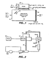
- Contaminant ion-purifying housing 10 defines a purifying flow channel 12, and includes an inlet 14 and an outlet 16.
- ion exchange resin 18 such as 8% cross linked Dowex resin
- flow channel 12 typically in the form of a column such as an IONPAC® ion trapping column.
- Other flow-through ion exchange material can be used such as a liquid permeable monolith.
- the monolithic may be of the type described in Example 7 of U.S. Patent 6,027,643 or some other form in which liquid can flow through porous ion exchange material without excessive pressure drops.
- a significant difference from the ion trap column is the application of an electric field across the resin.
- Spaced electrodes of opposite charge are disposed to apply such field as across the resin bed 18 in flow channel 12.
- one electrode 20 is disposed at or near the exit from the flow channel while an electrode of opposite charge 22 is disposed in a position to apply an electric field across a portion of the resin bed.
- Electrode 22 is generally parallel to the flow of eluent through flow channel 12 and is disposed in an electrode chamber 26.
- a barrier 24 in the form of a charged perm selective membrane described below. Barrier 24 substantially prevents bulk liquid flow while providing an ion transport bridge for ions of the same charge as the contaminant ions.
- barrier 24 is transverse to flow across the flow channel 12.
- Electrode 22, barrier 24 and chamber 26 may be of the type described in FIG. 2 of U.S. Patent 6,027,643 .
- Electrodes 58 and 60 may be contained within different electrode chambers, not shown. Solution flowing through one of the chambers can be recycled to the other chamber to carry the electrolysis products to waste.
- a suitable DC power supply not shown, connects the anode and cathode to provide a continuous electrical path between the anode and cathode through barrier 24 across the resin bed.
- the invention will be described with respect to the purification of sodium hydroxide eluent by removal of carbonate ions.
- the sodium hydroxide aqueous eluent enters as a flowing stream through inlet 14.
- Resin bed 18 is an ion exchange medium in a packed bed or monolithic form including exchangeable anions, hydroxide or carbonate ion, of opposite charge to the electrolyte selected ion, sodium ion.
- barrier 24 is an anionic exchange membrane with exchangeable ions of the same charge as the contaminant ions.
- the contaminant ions are drawn towards anode 22 disposed in electrode chamber 26.
- the electrolytic water splitting reaction occurs at the cathode to form hydroxide ions and hydrogen gas.
- Anionic contaminants in the stream are trapped by ion exchange on the regenerated resin surface and are directed along with hydroxide ions towards the anode by the applied field and exit the device as an acid at the anode.
- the resin is simultaneously regenerated by the transport of hydroxide ions toward the anode.
- an aqueous solution either recycled from a downstream chromatography analysis system or from an independent source 28 flows into an inlet, not shown, of electrode chamber 26 and out an outlet 30.
- Water in electrode chamber 26 is electrolyzed to hydronium ions and oxygen and anionic contaminant ions, such as carbonate ions, are converted to carbonic acid or other acid for removal as a waste stream in outlet 30.
- the purified eluent and the sample anions are directed to a conventional chromatography column for separation.
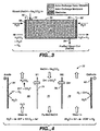
- the electrolytic purifier of FIG. 1 is used in an ion chromatography system wherein the suppressor is of the membrane type and the regenerant solution is used as a flowing stream for the electrode chamber of the electrolytic purifier to continuously remove the acid contaminant continuously.
- the eluent is pumped by pump 30 through an electrolytic purifier of the type illustrated in FIG. 1 , including purifier housing 10 and electrode chamber 26. From there, the eluent can flow through a conventional degassing unit 32, e.g., of the type sold by Dionex Corporation, past a sample injector 34, into a chromatography column 36 and to a self-regenerating sandwich membrane suppressor 38 of the type described in U.S.
- Patent 5,352,360 and of the type sold by Dionex Corporation under the SRS® name.
- the separated sample ions are detected, suitably by flowing through a conductivity cell 40 of a conductivity detector.
- Recycled aqueous liquid from the cell is utilized as the regenerant solution on the opposite side of the membrane as illustrated in the above patent.
- the regenerant solution from membrane suppressor 38 flows in line 42 through electrode chamber 26 and serves as the solution to carry away the acid and water formed in electrode chamber 26 so that the system can be operated continuously.
- the effluent from chamber 26 flows in line 42 can be passed directly to waste or as illustrated in FIG. 2 , can be used as the solution on the opposite side of a degassing membrane in a degassing apparatus, such as illustrated in U.S. Patent 5,045,204 , to carry the gas away from the purified effluent prior to passing to the chromatographic column 36.
- the removal of the electrolytic gases from the purified eluent can be accomplished by methods disclosed in the prior art such as by flowing the purified eluent through gas permeable membrane tubings.
- An external sweep solution may be incorporated to aid removal of the permeated gas. It is also possible to apply vacuum on the outside of such gas permeable tubings.
- An alternate solution using the principles of Boyle's law is to compress the gas as disclosed in Small U.S. Patent 6,316,270 . This compression can be accomplished by increasing the chromatographic system backpressure by adding restriction tubing of small bore diameter such as 0.003" id PEEK tubings from Upchurch.
- the potential electrolysis gas problem is overcome by isolating the electrodes from the eluent pathway so that the gases are also isolated.
- An eluent including sodium hydroxide and carbonate ion flows through purifier housing 50 containing an ion exchange medium in the form of a resin bed 52 through inlet 54.
- a barrier 56 formed of an ion exchange membrane, which may be of same type as membrane 24, is disposed adjacent anode 58 in an anode chamber, not shown.
- An aqueous stream flows through the cathode chamber. Carbonate and/or other anion contaminants are transported across barrier 56 into the anode chamber adjacent anode 58 so that carbonic acid is formed at anode 58.
- Electrolysis gas, oxygen, is formed at the anode isolated from the eluent flow.
- Eluent flowing into inlet 54 preferably is proximal to membrane 56 and flows into the inlet side of resin bed 52.
- anionic membrane 60 and cathode electrode 62 are disposed on the opposite side of resin bed from membrane 58 in a cathode chamber, not shown.
- the eluent solution flows from inlet 54 across resin bed 52 towards membrane 60 and out via outlet 64.
- Hydrogen gas generated electrolytically at the cathode is also isolated from the eluent stream.
- the purified eluent flowing out of outlet 64 does not have to be degasified because the electrolysis gases are isolated by the membrane.
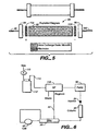
- FIG. 4 another form of the invention is schematically illustrated in which purification occurs in apparatus constructed like a commercially available SRS® sandwich membrane suppressor for cation applications sold by Dionex Corporation. Such an apparatus is illustrated in U.S. Patent 5,352,360 .
- This system is illustrated using an eluent to be purified in the form of sodium hydroxide including carbonate contaminant flowing through the central flow channel 70 of membrane purifier 72.
- Channel 70 is defined by membranes 74 and 76 extending along the length of the flow path.
- the outside of the sandwich comprises solution flow channel 78 and 80.
- Cathode 82 and anode 84 are in electrical communication with flow channels 78 and 80.
- membranes 74 and 76 are selectively permeable to anions but block cations and bulk liquid flow.
- the solutions in flow channels 78 and 80 can be water or other aqueous stream, which flows to waste.
- the sodium ion in the eluent does not cross anion exchange membranes 74 and 76.
- water is electrolyzed to hydrogen gas (isolated from the eluent stream) and hydroxide.
- the hydroxide ions pass through membranes 76 into flow channel 70.
- the carbonate then flows across membrane 74 into flow channel 80 adjacent anode 84.
- water is hydrolyzed into hydronium ions and oxygen gas (isolated from the eluent stream).
- the hydronium ions and carbonate ions combine to form carbonic acid, which is carried out of the membrane suppressor in a waste stream.
- the flow in outboard channels 78 and 80 is countercurrent to the flow in eluent channel 70.
- the potential applied across electrodes 82 and 84 increases the kinetics of ion flow across the membranes to increase the efficiency of the transfer.
- the principles of operation of the membrane purifier are analogous to suppression as disclosed in U.S. Patent 5,352,360 but for the purpose of purification.
- a purifier of this type may be used on the low-pressure side of a pump.
- an electrolytic purifier is illustrated as similar to that of FIG. 3 but wherein the ion exchange bed is in direct contact with the electrodes in the flow pathway.
- purifier 90 of this embodiment includes an ion exchange resin bed 92 held together by column end fittings 94 and 96 through which an inlet and outlet tubing 98 and 100, respectively, project.
- the ion exchange resin can be of the same type as discussed in FIG. 3 .
- Flow-through anode 102 and cathode 104 are disposed at the inlet and outlet ends, respectively, of resin bed 92.
- the ion exchange bed 92 is in direct contact with the electrodes.
- a degassing unit is preferably used in this embodiment.
- the carbonate ions are drawn to anode 102 away from the outlet while much of the bed is in the hydroxide form. Eventually, the bed becomes exhausted. Then, the polarity can be reversed and a liquid can flow through the system to regenerate the anion exchange resin.
- the system can be combined with suitable valving with another ion exchange resin bed device of the same type so that one bed is being used while the other one is regenerated followed by switching. Switching can occur before or after each run or after five or more runs. This type of valving is illustrated hereinafter.
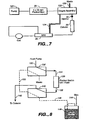
- FIG. 6 an embodiment of the invention similar to that of FIG. 2 is illustrated in which an electrolytic purifier of the type illustrated in FIG. 4 is disposed on the low pressure side of the eluent pump.
- Gas from source 110 forces the eluent solution in container 112 through line 114 into eluent purifier 116. Since the eluent is isolated from the purifier illustrated in chambers 78 and 80 illustrated in FIG. 4 , there is no gas in the purified eluent and thus no need to use a degas assembly.
- FIG. 7 another embodiment of the invention is illustrated in which the electrolytic purifier of FIG. 5 is used in combination with a degas assembly.
- Eluent from pump 120 flows through electrolytic purifier 90, flanked by electrodes, not shown, to a degas assembly 122 and from there through sample injector 34, through column 36, to a self-regenerating membrane suppressor of the type described above.
- Solution from the regenerant chamber of suppressor 38 flows through line 124 to the degas assembly and serves as the solution to carry the gas to waste.
- the eluent solution flows through a porous tubing and the gas permeates through the outer diameter of the porous the tubing into the solution outside the tubing to flow to waste in line 126.
- a second aspect of the invention includes appropriate valving and one or more packed beds, which can be regenerated electrolytically.
- One difference of these embodiments from the prior art traps is that the system can operate continuously while alternate regeneration of one or more packed beds occur after one or more runs.
- FIGS. 8 and 9 an arrangement is illustrated using a single packed bed and with valving to switch a purifier between online and regeneration modes, respectively.
- an eluent such as a NaOH is supplied at tubing 130 to valve 132, line 134 to a purifier 136 in the form of a packed bed of anion exchange resin initially in hydroxide form.
- Eluent from bed 136 flows through line 138 to valve 140 and from there in line 142 to a chromatography column, not shown, with an analyte for separation and detection as in a conventional chromatography or ion chromatography system.
- the system also illustrates a source of pressurized gas 144 to pressurize regenerant solution in reservoir 146, filled with NaOH or other hydroxide.
- the liquid in reservoir 146 is connected by tubing 148 to valve 140 and to valve 132 by tubing 150.
- valve 140 In the valve position illustrated in FIG. 8 , there is no flow from reservoir 146 to the purifier 136. In this valve position the flow of regenerant out of the reservoir 146 may be switched off by using a gas-switching valve (not shown) installed in line 144.
- FIG. 9 the system of FIG. 8 is illustrated with the valving switched to a second position for regeneration of purifier 136.
- the regenerant solution NaOH
- the valving can be selected to regenerate the packed bed after each chromatographic run or multiple runs if desired. If done after each run, regeneration can occur frequently without the need for a second column. This has the advantage of not permitting the bed of resin in purifier 136 to become so depleted of hydroxide ion that eluent contamination could interfere with chromatographic analysis.
- purifier 136 is shown on the high pressure side of the pump. It may also be used on the low pressure side of the pump.
- FIG. 10 (not according to the invention), another arrangement is illustrated, using chemical regeneration and two packed bed purifiers with valving to alternate flow between online use and regeneration.
- Detail of suitable valving used for suppression is illustrated in U.S. Patent 5,597,734 .
- Like parts in the system with respect to FIGS. 8 and 9 will be designated with like numbers for the system of FIG. 10 .
- valves of similar type to FIGS. 8 and 9 with connecting elements will be designated 150 and 152.
- valve 152 is connected by line 154 to a second packed bed purifier 156 and to line 158 back to valve 150.
- regenerant solution from reservoir 146 flows through line 148 to a second packed bed purifier 156 to regenerate the same.
- the effluent from purifier 156 flows in line 158 through valve 150 and to waste.
- valve 150 and 152 are reversed for regeneration.
- Regenerant solution from reservoir 146 flows through line 148, valve 152 to purifier 136 for regeneration and through line 134, and valve 150 to waste.
- eluent solution from a pump flows through line 130, valve 150 through purifier i 56, valve 152, line 158 and to a chromatography column.
- the systems can be regenerated after each chromatography run or several or more runs by switching the valve settings at appropriate intervals.
- FIG. 12 a device with valving of the type illustrated in FIG. 8 is employed with the exception that regeneration is performed electrolytically and the solution in reservoir 146 can be water rather than NaOH.
- the solution in reservoir 146 can be water rather than NaOH.
- Cathode 160 disposed at the inlet of the packed bed in purifier 136 and anode 162 is disposed at the outlet end of purifier 136 suitably is in the form illustrated in FIG. 5 but is illustrated in FIG. 12 in the regeneration mode.
- Regeneration can occur with any desired frequency such as after each run by electrolytic operation using water from supply 146 or some other supply.
- the device is electrically polarized during regeneration and the electrolytically formed ions regenerate the packed bed.
- the aqueous liquid used to regenerate the packed bed eluent purifier is supplied from a self-regenerating sandwich membrane suppressor as illustrated in U.S. Patent 5,352,360 .
- eluent in line 142 flows past injector 168 through column 170 to separate analytes and then through line 172 to suppressor 174 through detector 176.
- the valving is reversed and the aqueous solution in the regenerant flow channel on the other side of the membrane from the sample flow channel in suppressor 174 flows through line 178 through valve 140 and line 138 to purifier 136.
- the electrodes are activated and the packed bed is electrolytically regenerated as set forth above.
- the detector cell effluent is used for electrolytic regeneration and then sent to waste.
- the liquid stream from cell 176 can be diverted to line 178 to regenerate packed bed 136, with the aqueous waste fluid diverted to suppressor 174 in the recycle mode, as illustrated in U.S. Patent 5,352,360 .
- FIG. 14 Another embodiment illustrated in FIG. 14 is similar to that of FIG. 11 (not according to the invention) in that one purifier is online while the other one is regenerated. The difference is that regeneration is performed electrolytically and so water can be used in the reservoir as the solution for regeneration. Like parts will be designated with like numbers.
- water from reservoir 146 flows through line 148 to valve 152 into packed bed purifier 156 and valve 150 to waste.
- Cathode 180 is disposed on the inlet side of purifier, 156 and 182 on the outlet side to permit electrical regeneration of the packed bed in purifier 156.
- other purifier 136 is online as illustrated. Electrodes, not shown, of the type illustrated for purifier 156 are used with purifier 136 but inactive in this valve setting. At a selected interval such as after each run, the valving is switched. The lines can be switched from one to the other by including appropriate mode of electrolytic regeneration to both purifiers but the voltage is only applied to the purifier being regenerated.
- valving is described with respect to the selective flow of a regenerant solution through the purifier (water for an electrolytic system and acid or base for a chemical system).
- a regenerant solution water for an electrolytic system and acid or base for a chemical system.
- appropriate valving could be used to selectively flow an aqueous rinse solution through the purifier, e.g., after regeneration with acid or base.
- the electrolytic suppressor disclosed in EP 1,074,837 can be adapted for continuous purification and regeneration by flowing the eluent solution through the disclosed suppressor.
- a barrier to bulk liquid flow is not required between the electrodes and the ion exchange resin bed.
- the foregoing method and apparatus can be used for removing anions and/or cations from an aqueous stream that does not include a developing electrolyte but which includes contaminant ions of the same charge as the analyte ions, positive or negative.
- the removed anions are replaced with electrolytically generated hydroxide ions and the removed cations are replaced with electrolytically generated hydronium ions.
- Such a purified water stream is suitable for ion chromatography analysis as a water stream for eluent generation or eluent dilution or as a sample diluent.
- a water stream is pumped into the eluent generator module to generate online eluents electrolytically.
- Such approaches are described in U.S. Patent Nos. 5,045,204 , 6,225,129 and 6,036,921 .
- the water stream that is diverted into the eluent generator module could be purified of contaminating cations or anions using the devices of the present invention.
- the contaminating anions in the water stream such as carbonate and chloride will be removed by the eluent purifier modules of the present invention.
- the remaining cations in the water stream will be suppressed by the suppressor hence low background is achievable with the present invention.
- the water stream in a laboratory or process environment could be contaminated due to a variety of reasons.
- the water stream during collection from a water purifier is exposed to atmospheric air and this result in dissolution of air borne contaminants such as carbon dioxide gas.
- the use of a carbon dioxide contaminated water stream for eluent generation would impact performance during ion chromatography analysis.
- the water stream will have residual ions that would increase the conductivity background and impact performance and response during ion chromatography analysis.
- the variations in water quality from laboratory to laboratory and from day to day can be minimized by using the method and apparatus of the present invention.
- Various types of water can be further purified by the devices of the present invention such as laboratory deionized water, reverse osmosis water, municipal tap water and the like.
- a DX500 Ion chromatography system was used for anion analysis.
- the analytical column was an AS11 column 4 x 250 mm, which was operated with the following gradient (0.5 - 38.25 mM).
- E1 DI water Flow 2 ml/min
- the suppressor was a Dionex ASPS UltraTM suppressor that was operated at an applied current of 100 mA in the normal recycle mode.
- the comparison of prior art approach to the present invention is shown.
- the eluent purifier design was similar to FIG. 1 and the plumping schematic was similar to FIG. 2 .
- the elect purifier was packed with 20 ⁇ fully aminated vinylbenzylchloride. 8% divinylbenzene resin in the hydroxide form.
- the ion exchange membrane in this example was an anion exchange membrane AMI-7001 from Membrane International, NJ.
- a commercially available trap column from Dionex Corporation was used in place of the eluent purifier.
- the applied current to the eluent purifier was 40 mA and the voltage was roughly 35V.
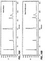
- FIG. 15 compares the results obtained from this study.
- a peak corresponding to carbonate was detected prominently when the eluent purifier was not used. The presence of this peak also impacted integration of sulfate, which eluted in close proximity to carbonate.
- the eluent purifier on the other hand did not have this issue. Sulfate was integrated better on the eluent purifier run as there was not shift in the baseline from carbonate contamination.
- the bottled eluent showed excessive shifts in the background.
- the drift observed for 15 minutes was roughly 1.05 uS/cm for the bottled eluent.
- the eluent purifier on the other hand showed no major shifts in the baseline.
- the typical drift observed for a 15 minute period was roughly 0.165 uS/cm.
- the eluent purifier showed superior performance when compared to a bottled eluent with a conventional trap column.
- the experimental setup was similar to Example 1 with the eluent purifier online.
- the chromatographic performance reproducibility was studied.
- the above results demonstrate excellent reproducibility of the eluent purifier.
- the experimental setup was similar to Example 1 with the eluent purifier online.
- the analytical column was an AS10 4 x 250 mm column, which was operated with the following: E1 50 mM NaOH E2 200 mM NaOH Time E1 E2 0 min 100 0 31 min 38 62 gradient (50 mM - 153 mM NaOH).
- the suppressor was an ASRS Ultra suppressor that was operated at an applied current of 300 mA in the normal recycle mode.
- ASRS Ultra suppressor that was operated at an applied current of 300 mA in the normal recycle mode.
- the eluent purifier design was similar to FIG. 1 and the plumbing schematic was similar to FIG. 2 .
- a commercially available trap column from Dionex Corporation was used in place of the eluent purifier.
- the applied current to the eluent purifier was 100 mA and the voltage was roughly 35V.
- a mixture comprising 5 anions were injected and analyzed.
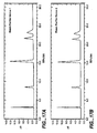
- the bottled eluent showed excessive shifts in the background as shown in FIG. 16 .
- the drift observed for 31 minutes was roughly 1.75 ⁇ S/cm for the bottled eluent.
- the eluent purifier on the other hand showed a drift for a 31 minute period of roughly 0.670 ⁇ S/cm.
- the eluent purifier showed superior performance when compared to a bottled eluent with a conventional trap column for this high concentration gradient. Note that the bottled eluent runs progressively became worse since the device capacity was exceeded due to the high ionic strength making it not very suitable for this application.
- Example 3 The experimental setup was similar to Example 3 with an eluent purifier online. Here, performance of two different eluent purifiers was compared using the same gradient shown in Example 3. The results indicate excellent device-to-device reproducibility of this approach as shown in FIG. 17 .
- the device of FIG. 3 was used as the eluent purifier. All other conditions were similar to Example 1 except there was no need to use the degas module. The electrodes were swept sequentially from the cathode followed by the anode by the SRS waste.
- the device of FIG. 4 was used.
- the anion exchange membranes and screens were radiation grafted TEFLON® and polyethylene materials, respectively.
- the gaskets for the screens in this device were made from parafilm.
- This device was plumbed in the low pressure side of the pump as shown in FIG. 6 . Since the eluent was isolated from the regenerant chamber, there was no gas in the purified eluent, hence there was no need to use a degas assembly.
- This device reduced the background similar to the other devices of the present invention suggesting excellent removal of anionic contaminants from the eluent stream.
- a device of FIG. 1 was used except the anion exchange resin and membrane were replaced with a cation exchange resin (20 ⁇ sulfonated polystyrene/8% divinylbenzene in the H+ form) and membrane (AMI-7000 a cation exchange membrane from Membrane International, NJ).
- the electrode on top of the membrane was designated the cathode in this example.
- the outlet electrode was designated the anode.
- This device was now suited for removing cationic impurities from the eluent, preferably acidic eluents.
- FIG. 5 A packed bed device with is a 4 x 35 mm column is fitted with flow through electrodes, and is packed with 20 ⁇ fully aminated vinylbenzylchloride-8% divinylbenzene resin in the hydroxide form (as shown in FIG. 5 ).
- the device was connected to a degas assembly and then connected to the rest of the system as shown in FIG. 7 .
- the device was first tested without polarization and showed excessive shifts similar to prior art trap column devices as shown in FIG. 18A .
- the device started purifying the eluent as soon as the power was applied as shown in FIG. 18B .
- the net result of applying the power according to the present invention improved the device capacity and its ability to remove ionic contaminants.
- the useful life of the packed bed device is extended.
- FIG. 8 a packed bed device, which is a 4 x 35mm column, is packed with 20 ⁇ fully animated vinylbenzylchloride-8% divinylbenzene resin in the hydroxide form, is used for removing anionic contaminants from the eluent.
- the device may be regenerated chemically by rinsing with sodium hydroxide after each run or may be regenerated after several runs as shown in FIG. 9 , thus allowing continuous operation.
- the device is shown on the high pressure side of the pump. It is also possible to implement the above design on the low pressure side of the pump.
- the packed bed device is regenerated chemically.
- the above device is suited for removing anionic impurities from a reagent stream.
- This example shows anion analysis.
- the packed bed is similar to the one shown in Example 9, except in this case two packed bed devices are used for purifying the eluent.
- One packed bed is being regenerated as shown in FIG. 10 , while the other packed bed is used for the purification process.
- the packed beds reverse their roles and this is shown in FIG. 11 where packed bed 2 now becomes the purifier while packed bed 1 is being regenerated.
- switching between the two packed bed devices enables continuous uninterrupted operation.
- This example shows anion analysis.
- a packed bed with electrodes as shown in FIG. 5 is used.
- the device is packed with 20 ⁇ fully aminated vinylbenzylchloride-8% divinylbenzene resin in the hydroxide form.
- the device can be used as shown in FIGS. 10 and 11 , with the exception that sodium hydroxide reagent is replaced with water.
- the device may be regenerated after each run or may be regenerated after several runs by electrically polarizing the packed bed. By regenerating this device offline, there is no need to deal with electrolytically generated gases, thus allowing continuous operation.
- the regeneration of this device is shown in FIG. 12 . Also note that in this figure the device is shown on the high pressure side of the pump.
- the packed bed device is regenerated electrolytically and requires a power supply to polarize the electrodes.
- the water required for the electrolytic process can be derived by pumping in the SRS wastes, thus eliminating the need for maintaining an external source of water as shown in FIG. 13 .
- This example shows anion analysis.
- a packed bed with electrodes as shown in FIG. 5 is used.
- the device is packed with 20 ⁇ fully aminated vinylbenzylchloride-8% divinylbenzene resin in the hydroxide form.
- the device can be used as shown in FIGS. 10 and 11 in a switching mode with water instead of sodium hydroxide as the regenerant.
- the device is electrically polarized during regeneration step where the electrolytically formed ions regenerate the packed bed as shown in FIG. 14 . Again, regeneration could be done after every run or after several runs, thus enabling continuous operation.
- the water required for the electrolytic process can be derived by pumping in the SRS wastes, thus eliminating the need for maintaining an external source of water.
- an aqueous stream without a developing electrolyte flows into inlet 14.
- the anionic contaminants are removed and replaced with hydroxide.
- Such a water stream is used to generate base using an eluent generator module.
- DI water is pumped into the purifier device and the purified water is diverted into a commercially available EG40 module from Dionex Corporation, and located fluidically between the purifier device 10 and the degas module 32.
- a Dionex eluent generator EG40 module generates base required for anion analysis.
- the purifier module purifies the DI water from anionic contaminants.
- the cationic contaminants are all suppressed in a suppressor and the conductivity cell detects a lower background due to the removed contaminants.
- a DI water sample stream spiked with anionic contaminants ranging from 20 to 150 ppb of various anions is pumped into a purifier device of the type illustrated in Figure 1 and the purified stream was diverted into a TACLP1 concentrator column from Dionex. 30 ml of the purified stream was concentrated on the concentrator column and then analyzed using a DX500 system and AS 15 chemistry with 38-mM NaOH eluent at 1.2 ml/min flow rate. An ASRS Ultra suppressor was used at 125 mA for this application. The purifying device removed trace anionic impurities from water. The removal efficiency was > 99.9% for all seven anions.
- a DX500 system was used for the cation analysis of house RO water.
- the water container was exposed to ambient laboratory conditions for several hours before analyzing the contents of the container.
- Cation analysis was done pursuing standard CS12A chemistry using 20 mM MSA eluent at 1 ml/min flow rate.
- the cation suppressor was a Dionex CSRS Ultra and was run at 100 mA for this application.
- a cation purifier device which is designed to remove cations, was used for this work. The same water when purified using the cation purifier device shows excellent removal efficiency for all ions.
- Several unknown contaminant peaks were removed by the purifier device illustrating the utility of the device of the present invention for water purifying applications.
- the purifier devices of example 14 and example 15 are combined together in this example.
- the water stream is pumped into these modules and the resulting purified water is collected for use with an auto sampler for dilution purposes.
- the resulting water is suitable as a diluent to prepare standards for chromatographic calibration.
Landscapes
- Chemical & Material Sciences (AREA)
- Engineering & Computer Science (AREA)
- Water Supply & Treatment (AREA)
- Chemical Kinetics & Catalysis (AREA)
- Life Sciences & Earth Sciences (AREA)
- Health & Medical Sciences (AREA)
- General Chemical & Material Sciences (AREA)
- Analytical Chemistry (AREA)
- Electrochemistry (AREA)
- Hydrology & Water Resources (AREA)
- Environmental & Geological Engineering (AREA)
- Organic Chemistry (AREA)
- Molecular Biology (AREA)
- Urology & Nephrology (AREA)
- Biochemistry (AREA)
- Physics & Mathematics (AREA)
- General Health & Medical Sciences (AREA)
- General Physics & Mathematics (AREA)
- Immunology (AREA)
- Pathology (AREA)
- Treatment Of Liquids With Adsorbents In General (AREA)
- Water Treatment By Electricity Or Magnetism (AREA)
- Separation Using Semi-Permeable Membranes (AREA)
Applications Claiming Priority (5)
| Application Number | Priority Date | Filing Date | Title |
|---|---|---|---|
| US43645 | 2002-01-10 | ||
| US10/043,645 US20030127392A1 (en) | 2002-01-10 | 2002-01-10 | Eluent purifier and method of use |
| US308865 | 2002-12-02 | ||
| US10/308,865 US7390386B2 (en) | 2002-01-10 | 2002-12-02 | Aqueous stream purifier and method of use |
| PCT/US2003/000641 WO2003059822A2 (en) | 2002-01-10 | 2003-01-08 | Chromatogtraphy apparatus and electrolytic method for purifying an aqueous stream containing a contaminant iom |
Publications (2)
| Publication Number | Publication Date |
|---|---|
| EP1463686A2 EP1463686A2 (en) | 2004-10-06 |
| EP1463686B1 true EP1463686B1 (en) | 2015-06-03 |
Family
ID=28793751
Family Applications (1)
| Application Number | Title | Priority Date | Filing Date |
|---|---|---|---|
| EP03729612.6A Expired - Lifetime EP1463686B1 (en) | 2002-01-10 | 2003-01-08 | Chromatography apparatus and electrolytic method for purifying an aqueous stream containing a contaminant ion |
Country Status (8)
| Country | Link |
|---|---|
| US (2) | US7390386B2 (enExample) |
| EP (1) | EP1463686B1 (enExample) |
| JP (1) | JP4033835B2 (enExample) |
| KR (1) | KR100918531B1 (enExample) |
| CN (1) | CN100340494C (enExample) |
| AU (1) | AU2003235683B2 (enExample) |
| CA (1) | CA2471705C (enExample) |
| WO (1) | WO2003059822A2 (enExample) |
Families Citing this family (22)
| Publication number | Priority date | Publication date | Assignee | Title |
|---|---|---|---|---|
| US6468804B1 (en) * | 1999-08-02 | 2002-10-22 | Alltech Associates, Inc. | Suppressor for continuous electrochemically suppressed ion chromatography and method |
| US8216515B2 (en) | 2004-09-16 | 2012-07-10 | Dionex Corporation | Capillary ion chromatography |
| JP4662277B2 (ja) * | 2006-04-18 | 2011-03-30 | オルガノ株式会社 | 電気脱イオン装置 |
| US7632404B2 (en) * | 2007-11-15 | 2009-12-15 | Dionex Corporation | Barrier with a seated ion exchange bead and method |
| US8597571B2 (en) * | 2008-01-28 | 2013-12-03 | Dionex Corporation | Electrolytic eluent recycle device, apparatus and method of use |
| JP5365116B2 (ja) * | 2008-09-19 | 2013-12-11 | 横河電機株式会社 | イオンクロマトグラフ測定装置およびイオンクロマトグラフ測定方法 |
| US9188573B2 (en) | 2010-01-20 | 2015-11-17 | Dionex Corporation | Multichannel ion chromatography system and method |
| US20110186441A1 (en) * | 2010-01-29 | 2011-08-04 | Conocophillips Company | Electrolytic recovery of retained carbon dioxide |
| US8414684B2 (en) | 2010-06-01 | 2013-04-09 | Dionex Corporation | High pressure degas assembly for chromatography system and method |
| US8449658B2 (en) | 2011-02-14 | 2013-05-28 | Dionex Corporation | High-pressure capillary degas assembly |
| US8529758B2 (en) | 2011-03-22 | 2013-09-10 | Dionex Corporation | CO2-removal device and method |
| EP2747880B1 (en) | 2011-08-23 | 2021-03-24 | Board Of Regents, The University Of Texas System | Electrolytic buffer generator |
| CN103267817B (zh) * | 2013-04-15 | 2015-09-02 | 江苏省环境监测中心 | 测定邻苯二甲酸酯类化合物用抗干扰装置 |
| CN103267816B (zh) * | 2013-04-15 | 2015-07-29 | 江苏省环境监测中心 | 测定邻苯二甲酸酯类化合物的方法 |
| US9964510B2 (en) | 2013-09-16 | 2018-05-08 | Dionex Corporation | Electrolytic four-channel device and method |
| US11090606B2 (en) | 2013-12-05 | 2021-08-17 | Dionex Corporation | Gas-less electrolytic device and method |
| US9931585B2 (en) | 2014-04-23 | 2018-04-03 | Dionex Corporation | Electrolytic device for contaminant removal and method |
| US20160137530A1 (en) | 2014-11-13 | 2016-05-19 | Dionex Corporation | Ion exchange based volatile component removal device for ion chromatography |
| CN109205744A (zh) * | 2018-11-19 | 2019-01-15 | 北京碧水源膜科技有限公司 | 一种低废水率的流动电极电吸附净水方法及净水机 |
| CN113493263A (zh) * | 2020-04-01 | 2021-10-12 | 佛山市云米电器科技有限公司 | 一种家用净水装置及其控制方法 |
| CN114082301B (zh) * | 2021-10-18 | 2024-04-09 | 江苏核电有限公司 | 核电厂冷却剂中同位素碘的分离系统、方法及检测方法 |
| CN114894942B (zh) * | 2022-03-16 | 2024-04-05 | 中国石油化工股份有限公司 | 一种快速检测醇胺溶液中热稳盐阴离子的装置及方法 |
Family Cites Families (21)
| Publication number | Priority date | Publication date | Assignee | Title |
|---|---|---|---|---|
| US3964985A (en) * | 1974-10-29 | 1976-06-22 | Ionics, Incorporated | Electrodialysis apparatus and process for ion modification |
| US4334949A (en) | 1980-11-25 | 1982-06-15 | International Business Machines Corporation | Reducing carbonate concentration in aqueous solution |
| US5045204A (en) | 1990-02-13 | 1991-09-03 | Dionex Corporation | Method and apparatus for generating a high purity chromatography eluent |
| CN2096559U (zh) * | 1991-08-06 | 1992-02-19 | 王百城 | 菌毒污水净化器 |
| FR2684093B1 (fr) | 1991-11-22 | 1994-01-21 | Sadon Pierre | Procede et dispositif de regeneration automatique d'une station de demineralisation. |
| US5518622A (en) | 1992-02-10 | 1996-05-21 | Dionex Corporation | Electrochemical pretreatment system for liquid sample analysis |
| US5248426A (en) | 1992-02-10 | 1993-09-28 | Dionex Corporation | Ion chromatography system using electrochemical suppression and detector effluent recycle |
| CN1075699A (zh) * | 1992-02-28 | 1993-09-01 | 王百城 | 菌毒污水净化器及其净化工艺方法 |
| WO1995006246A1 (en) | 1993-08-27 | 1995-03-02 | Dionex Corporation | Ion chromatography using frequent regeneration of batch-type suppressor |
| JPH09511838A (ja) * | 1995-03-03 | 1997-11-25 | オールテック アソシエイツ インコーポレイテッド | クロマトグラフィー物質を電気化学的に改良するための装置/方法 |
| US5633171A (en) * | 1995-03-03 | 1997-05-27 | Dionex Corporation | Intermittent electrolytic packed bed suppressor regeneration for ion chromatography |
| US6036921A (en) | 1997-01-15 | 2000-03-14 | Dionex Corporation | Acid or base generator with chromatograph |
| US6027643A (en) | 1997-09-04 | 2000-02-22 | Dionex Corporation | Ion chromatographic method and apparatus using a combined suppressor and eluent generator |
| US6225129B1 (en) | 1998-02-02 | 2001-05-01 | Dionex Corporation | Large capacity acid or base generation apparatus and method of use |
| US6402917B1 (en) * | 1998-02-09 | 2002-06-11 | Otv Societe Anonyme | Electrodialysis apparatus |
| US6077434A (en) * | 1999-01-15 | 2000-06-20 | Dionex Corporation | Current-efficient suppressors and method of use |
| US6468804B1 (en) | 1999-08-02 | 2002-10-22 | Alltech Associates, Inc. | Suppressor for continuous electrochemically suppressed ion chromatography and method |
| AU7143700A (en) * | 1999-11-19 | 2001-05-24 | Rohm And Haas Company | Water treatment method and apparatus |
| US6526811B2 (en) | 2000-02-23 | 2003-03-04 | Jmic, Inc. | Analytical apparatus for measurement of low concentration constituent, method of measurement and calibration using the same |
| CN2430434Y (zh) * | 2000-05-29 | 2001-05-16 | 陈斌 | 污水处理装置 |
| US6808608B2 (en) * | 2002-03-13 | 2004-10-26 | Dionex Corporation | Water purifier and method |
-
2002
- 2002-12-02 US US10/308,865 patent/US7390386B2/en not_active Expired - Lifetime
-
2003
- 2003-01-08 WO PCT/US2003/000641 patent/WO2003059822A2/en not_active Ceased
- 2003-01-08 CN CNB038056305A patent/CN100340494C/zh not_active Expired - Lifetime
- 2003-01-08 EP EP03729612.6A patent/EP1463686B1/en not_active Expired - Lifetime
- 2003-01-08 AU AU2003235683A patent/AU2003235683B2/en not_active Expired
- 2003-01-08 JP JP2003559932A patent/JP4033835B2/ja not_active Expired - Lifetime
- 2003-01-08 KR KR1020047010781A patent/KR100918531B1/ko not_active Expired - Lifetime
- 2003-01-08 CA CA2471705A patent/CA2471705C/en not_active Expired - Lifetime
-
2008
- 2008-03-05 US US12/043,024 patent/US7704749B2/en not_active Expired - Lifetime
Also Published As
| Publication number | Publication date |
|---|---|
| AU2003235683A2 (en) | 2003-07-30 |
| JP4033835B2 (ja) | 2008-01-16 |
| WO2003059822A3 (en) | 2003-10-16 |
| KR20040078121A (ko) | 2004-09-08 |
| CN1639073A (zh) | 2005-07-13 |
| AU2003235683B2 (en) | 2008-09-04 |
| CN100340494C (zh) | 2007-10-03 |
| US7390386B2 (en) | 2008-06-24 |
| CA2471705C (en) | 2011-04-19 |
| HK1075242A1 (en) | 2005-12-09 |
| US20080173587A1 (en) | 2008-07-24 |
| US20030132163A1 (en) | 2003-07-17 |
| US7704749B2 (en) | 2010-04-27 |
| KR100918531B1 (ko) | 2009-09-21 |
| JP2005515055A (ja) | 2005-05-26 |
| CA2471705A1 (en) | 2003-07-24 |
| AU2003235683A1 (en) | 2003-07-30 |
| EP1463686A2 (en) | 2004-10-06 |
| WO2003059822A2 (en) | 2003-07-24 |
Similar Documents
| Publication | Publication Date | Title |
|---|---|---|
| US7704749B2 (en) | Aqueous stream purifier and method of use | |
| CA2188161C (en) | Intermittent electrolytic packed bed suppressor regeneration for ion chromatography | |
| AU754051B2 (en) | Continuous electrolytically regenerated packed bed suppressor for ion chromatography | |
| US6808608B2 (en) | Water purifier and method | |
| US7767462B2 (en) | Electrolytic eluent generator and method of use | |
| AU2006292705B2 (en) | Recycling of suppressor regenerants | |
| US20030127392A1 (en) | Eluent purifier and method of use | |
| EP2848933B1 (en) | Electrolytic four-channel device and method | |
| EP2937690B1 (en) | Electrolytic device for contaminant removal and method | |
| HK1075242B (en) | Chromatography apparatus and electrolytic method for purifying an aqueous stream containing a contaminant ion | |
| HK1076267B (en) | Electrolytic eluent generator and method of use |
Legal Events
| Date | Code | Title | Description |
|---|---|---|---|
| PUAI | Public reference made under article 153(3) epc to a published international application that has entered the european phase |
Free format text: ORIGINAL CODE: 0009012 |
|
| 17P | Request for examination filed |
Effective date: 20040721 |
|
| AK | Designated contracting states |
Kind code of ref document: A2 Designated state(s): AT BE BG CH CY CZ DE DK EE ES FI FR GB GR HU IE IT LI LU MC NL PT SE SI SK TR |
|
| AX | Request for extension of the european patent |
Extension state: AL LT LV MK RO |
|
| RIN1 | Information on inventor provided before grant (corrected) |
Inventor name: SRINIVASAN, KANNAN Inventor name: AVDALOVIC, NEBOJSA |
|
| 17Q | First examination report despatched |
Effective date: 20050811 |
|
| GRAP | Despatch of communication of intention to grant a patent |
Free format text: ORIGINAL CODE: EPIDOSNIGR1 |
|
| INTG | Intention to grant announced |
Effective date: 20140602 |
|
| GRAP | Despatch of communication of intention to grant a patent |
Free format text: ORIGINAL CODE: EPIDOSNIGR1 |
|
| INTG | Intention to grant announced |
Effective date: 20141117 |
|
| GRAS | Grant fee paid |
Free format text: ORIGINAL CODE: EPIDOSNIGR3 |
|
| GRAA | (expected) grant |
Free format text: ORIGINAL CODE: 0009210 |
|
| AK | Designated contracting states |
Kind code of ref document: B1 Designated state(s): AT BE BG CH CY CZ DE DK EE ES FI FR GB GR HU IE IT LI LU MC NL PT SE SI SK TR |
|
| RAP1 | Party data changed (applicant data changed or rights of an application transferred) |
Owner name: DIONEX CORPORATION |
|
| REG | Reference to a national code |
Ref country code: GB Ref legal event code: FG4D |
|
| REG | Reference to a national code |
Ref country code: CH Ref legal event code: EP |
|
| REG | Reference to a national code |
Ref country code: IE Ref legal event code: FG4D |
|
| REG | Reference to a national code |
Ref country code: AT Ref legal event code: REF Ref document number: 729811 Country of ref document: AT Kind code of ref document: T Effective date: 20150715 |
|
| REG | Reference to a national code |
Ref country code: DE Ref legal event code: R096 Ref document number: 60347680 Country of ref document: DE |
|
| REG | Reference to a national code |
Ref country code: AT Ref legal event code: MK05 Ref document number: 729811 Country of ref document: AT Kind code of ref document: T Effective date: 20150603 |
|
| PG25 | Lapsed in a contracting state [announced via postgrant information from national office to epo] |
Ref country code: FI Free format text: LAPSE BECAUSE OF FAILURE TO SUBMIT A TRANSLATION OF THE DESCRIPTION OR TO PAY THE FEE WITHIN THE PRESCRIBED TIME-LIMIT Effective date: 20150603 Ref country code: ES Free format text: LAPSE BECAUSE OF FAILURE TO SUBMIT A TRANSLATION OF THE DESCRIPTION OR TO PAY THE FEE WITHIN THE PRESCRIBED TIME-LIMIT Effective date: 20150603 |
|
| REG | Reference to a national code |
Ref country code: NL Ref legal event code: MP Effective date: 20150603 |
|
| PG25 | Lapsed in a contracting state [announced via postgrant information from national office to epo] |
Ref country code: GR Free format text: LAPSE BECAUSE OF FAILURE TO SUBMIT A TRANSLATION OF THE DESCRIPTION OR TO PAY THE FEE WITHIN THE PRESCRIBED TIME-LIMIT Effective date: 20150904 Ref country code: BG Free format text: LAPSE BECAUSE OF FAILURE TO SUBMIT A TRANSLATION OF THE DESCRIPTION OR TO PAY THE FEE WITHIN THE PRESCRIBED TIME-LIMIT Effective date: 20150903 Ref country code: AT Free format text: LAPSE BECAUSE OF FAILURE TO SUBMIT A TRANSLATION OF THE DESCRIPTION OR TO PAY THE FEE WITHIN THE PRESCRIBED TIME-LIMIT Effective date: 20150603 |
|
| REG | Reference to a national code |
Ref country code: FR Ref legal event code: PLFP Year of fee payment: 14 |
|
| PG25 | Lapsed in a contracting state [announced via postgrant information from national office to epo] |
Ref country code: EE Free format text: LAPSE BECAUSE OF FAILURE TO SUBMIT A TRANSLATION OF THE DESCRIPTION OR TO PAY THE FEE WITHIN THE PRESCRIBED TIME-LIMIT Effective date: 20150603 |
|
| PG25 | Lapsed in a contracting state [announced via postgrant information from national office to epo] |
Ref country code: SK Free format text: LAPSE BECAUSE OF FAILURE TO SUBMIT A TRANSLATION OF THE DESCRIPTION OR TO PAY THE FEE WITHIN THE PRESCRIBED TIME-LIMIT Effective date: 20150603 Ref country code: PT Free format text: LAPSE BECAUSE OF FAILURE TO SUBMIT A TRANSLATION OF THE DESCRIPTION OR TO PAY THE FEE WITHIN THE PRESCRIBED TIME-LIMIT Effective date: 20151006 Ref country code: CZ Free format text: LAPSE BECAUSE OF FAILURE TO SUBMIT A TRANSLATION OF THE DESCRIPTION OR TO PAY THE FEE WITHIN THE PRESCRIBED TIME-LIMIT Effective date: 20150603 |
|
| REG | Reference to a national code |
Ref country code: DE Ref legal event code: R097 Ref document number: 60347680 Country of ref document: DE |
|
| PLBE | No opposition filed within time limit |
Free format text: ORIGINAL CODE: 0009261 |
|
| STAA | Information on the status of an ep patent application or granted ep patent |
Free format text: STATUS: NO OPPOSITION FILED WITHIN TIME LIMIT |
|
| PG25 | Lapsed in a contracting state [announced via postgrant information from national office to epo] |
Ref country code: IT Free format text: LAPSE BECAUSE OF FAILURE TO SUBMIT A TRANSLATION OF THE DESCRIPTION OR TO PAY THE FEE WITHIN THE PRESCRIBED TIME-LIMIT Effective date: 20150603 Ref country code: DK Free format text: LAPSE BECAUSE OF FAILURE TO SUBMIT A TRANSLATION OF THE DESCRIPTION OR TO PAY THE FEE WITHIN THE PRESCRIBED TIME-LIMIT Effective date: 20150603 |
|
| 26N | No opposition filed |
Effective date: 20160304 |
|
| PG25 | Lapsed in a contracting state [announced via postgrant information from national office to epo] |
Ref country code: BE Free format text: LAPSE BECAUSE OF NON-PAYMENT OF DUE FEES Effective date: 20160131 Ref country code: SI Free format text: LAPSE BECAUSE OF FAILURE TO SUBMIT A TRANSLATION OF THE DESCRIPTION OR TO PAY THE FEE WITHIN THE PRESCRIBED TIME-LIMIT Effective date: 20150603 |
|
| PG25 | Lapsed in a contracting state [announced via postgrant information from national office to epo] |
Ref country code: LU Free format text: LAPSE BECAUSE OF FAILURE TO SUBMIT A TRANSLATION OF THE DESCRIPTION OR TO PAY THE FEE WITHIN THE PRESCRIBED TIME-LIMIT Effective date: 20160108 |
|
| PG25 | Lapsed in a contracting state [announced via postgrant information from national office to epo] |
Ref country code: MC Free format text: LAPSE BECAUSE OF FAILURE TO SUBMIT A TRANSLATION OF THE DESCRIPTION OR TO PAY THE FEE WITHIN THE PRESCRIBED TIME-LIMIT Effective date: 20150603 |
|
| REG | Reference to a national code |
Ref country code: IE Ref legal event code: MM4A |
|
| REG | Reference to a national code |
Ref country code: FR Ref legal event code: PLFP Year of fee payment: 15 |
|
| PG25 | Lapsed in a contracting state [announced via postgrant information from national office to epo] |
Ref country code: BE Free format text: LAPSE BECAUSE OF FAILURE TO SUBMIT A TRANSLATION OF THE DESCRIPTION OR TO PAY THE FEE WITHIN THE PRESCRIBED TIME-LIMIT Effective date: 20150603 |
|
| PG25 | Lapsed in a contracting state [announced via postgrant information from national office to epo] |
Ref country code: IE Free format text: LAPSE BECAUSE OF NON-PAYMENT OF DUE FEES Effective date: 20160108 |
|
| PG25 | Lapsed in a contracting state [announced via postgrant information from national office to epo] |
Ref country code: NL Free format text: LAPSE BECAUSE OF FAILURE TO SUBMIT A TRANSLATION OF THE DESCRIPTION OR TO PAY THE FEE WITHIN THE PRESCRIBED TIME-LIMIT Effective date: 20150603 Ref country code: SE Free format text: LAPSE BECAUSE OF FAILURE TO SUBMIT A TRANSLATION OF THE DESCRIPTION OR TO PAY THE FEE WITHIN THE PRESCRIBED TIME-LIMIT Effective date: 20150603 |
|
| REG | Reference to a national code |
Ref country code: FR Ref legal event code: PLFP Year of fee payment: 16 |
|
| PG25 | Lapsed in a contracting state [announced via postgrant information from national office to epo] |
Ref country code: HU Free format text: LAPSE BECAUSE OF FAILURE TO SUBMIT A TRANSLATION OF THE DESCRIPTION OR TO PAY THE FEE WITHIN THE PRESCRIBED TIME-LIMIT; INVALID AB INITIO Effective date: 20030108 Ref country code: CY Free format text: LAPSE BECAUSE OF FAILURE TO SUBMIT A TRANSLATION OF THE DESCRIPTION OR TO PAY THE FEE WITHIN THE PRESCRIBED TIME-LIMIT Effective date: 20150603 |
|
| PG25 | Lapsed in a contracting state [announced via postgrant information from national office to epo] |
Ref country code: TR Free format text: LAPSE BECAUSE OF FAILURE TO SUBMIT A TRANSLATION OF THE DESCRIPTION OR TO PAY THE FEE WITHIN THE PRESCRIBED TIME-LIMIT Effective date: 20150603 |
|
| PGFP | Annual fee paid to national office [announced via postgrant information from national office to epo] |
Ref country code: FR Payment date: 20211217 Year of fee payment: 20 Ref country code: GB Payment date: 20211206 Year of fee payment: 20 |
|
| PGFP | Annual fee paid to national office [announced via postgrant information from national office to epo] |
Ref country code: CH Payment date: 20211216 Year of fee payment: 20 |
|
| PGFP | Annual fee paid to national office [announced via postgrant information from national office to epo] |
Ref country code: DE Payment date: 20211130 Year of fee payment: 20 |
|
| REG | Reference to a national code |
Ref country code: DE Ref legal event code: R071 Ref document number: 60347680 Country of ref document: DE |
|
| REG | Reference to a national code |
Ref country code: CH Ref legal event code: PL |
|
| REG | Reference to a national code |
Ref country code: GB Ref legal event code: PE20 Expiry date: 20230107 |
|
| PG25 | Lapsed in a contracting state [announced via postgrant information from national office to epo] |
Ref country code: GB Free format text: LAPSE BECAUSE OF EXPIRATION OF PROTECTION Effective date: 20230107 |