EP1460773A1 - UWB- Kommunikationsverfahren und Kommunikationssystem - Google Patents
UWB- Kommunikationsverfahren und Kommunikationssystem Download PDFInfo
- Publication number
- EP1460773A1 EP1460773A1 EP04101036A EP04101036A EP1460773A1 EP 1460773 A1 EP1460773 A1 EP 1460773A1 EP 04101036 A EP04101036 A EP 04101036A EP 04101036 A EP04101036 A EP 04101036A EP 1460773 A1 EP1460773 A1 EP 1460773A1
- Authority
- EP
- European Patent Office
- Prior art keywords
- station
- master station
- user
- pulses
- user stations
- Prior art date
- Legal status (The legal status is an assumption and is not a legal conclusion. Google has not performed a legal analysis and makes no representation as to the accuracy of the status listed.)
- Ceased
Links
Images


Classifications
-
- H—ELECTRICITY
- H04—ELECTRIC COMMUNICATION TECHNIQUE
- H04B—TRANSMISSION
- H04B1/00—Details of transmission systems, not covered by a single one of groups H04B3/00 - H04B13/00; Details of transmission systems not characterised by the medium used for transmission
- H04B1/69—Spread spectrum techniques
- H04B1/7163—Spread spectrum techniques using impulse radio
- H04B1/7183—Synchronisation
Definitions
- the invention relates in particular to a method and a communication system for example in a communications network supporting a UWB type protocol and in which the transmissions are carried out by pulses.
- 'HOTSPOT in the telecommunications literature. It mainly concerns 'general public' applications such as data servers in airports, stations or shopping centers but can also be deployed temporarily for intervention teams (firefighters, doctors, special forces, maintenance teams in areas at risk, ..).
- TDMA Time Division Multiple Access
- CSMA / CA Carrier Sense Multiple Access / Collision Avoidance
- TDMA Time Division Multiple Access
- the CSMA / CA is based on random, therefore non-deterministic, access, which makes it ineffective for services requiring constant quality of service, in terms of regularity and time.
- This protocol notably has the advantages of offering equal access to the support and simplicity of implementation.
- its performances are average in terms of bit rate because on the one hand of the time intervals lost between the transmissions of frames and on the other hand of the collisions.
- the time is divided regularly into frames of fixed length, themselves divided into different areas with different vocations.
- a station plays the role of network coordinator by allocating the resources of each frame to the different users according to their needs. It is called the central station or even 'master' station.
- a station wishing to transmit must therefore always make a prior request to this master station, which then allocates a time resource proportional to its needs, subject to sufficient availability.
- the current efficiency of a TDMA protocol applied to UWB is less than that obtained with narrowband transmission methods.
- the cause of this low efficiency is on the one hand the long time required for synchronization in a UWB transmission, which can go up to several milliseconds (depending on the length of the acquisition codes and the reception structure) and d on the other hand, the specificity of the pulse waveform is not taken into account.
- the low duty cycle of the pulses used in UWB (of the order of 1%) means that one can take advantage of wide ranges of "silence".
- a conventional TDMA is applied to separate two users, that is to say by having them transmit one after the other, the unused times between the pulses of the same user are lost. This time interval allows the impulse response to flow following the emission of a pulse by any station.
- the pulses emitted by the same user station or by several different stations are brought together as much as possible, in both directions of the communication (from the central station to the users and vice versa).
- a precise synchronization technique objective: 1 ns for example
- fine user stations followed by a technique of equalization of the transmission channel on the pulses at reception, in order to combat interference between pulses successive.
- the method can perform a complementary interleaving of the pulse trains either of the different users bound for the central station or from the central station to the users.
- the idea is in particular to offer a TDMA protocol optimized for the UWB physical layer, allowing high speeds to be achieved while maintaining a constant quality of service.
- central station and “master station” designate a similar element depending on the type of application.
- the method comprises for example a step of interleaving the signals exchanged from the user stations to the master station and / or a step of interleaving the signals exchanged from the master station to the user stations.
- the invention is for example used in a centralized network or in a network supporting a UWB transmission layer.
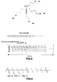
- FIG. 1 diagrammatically shows a frame according to the prior art in a radio network with TDMA access.
- a centralized communications network according to the invention with access of the UWB type, more generally with impulse transmissions, is shown diagrammatically in FIG. 2. It comprises for example a central station 1 or master station and different user stations 2i (a only station is represented for reasons of simplicity). The transmissions are carried out in uplink or downlink. The central station and the user stations are provided with processors adapted to implement an equalization technique.
- the central station is equipped with a processor adapted to give the distribution of network users (for example their position, etc.), to allocate the TDMA time resources, the time offset to be applied in the uplink direction (which corresponds synchronization between the different users) and possibly the integration factor (number of pulses per bit) to be used for each station.
- a processor adapted to give the distribution of network users (for example their position, etc.), to allocate the TDMA time resources, the time offset to be applied in the uplink direction (which corresponds synchronization between the different users) and possibly the integration factor (number of pulses per bit) to be used for each station.
- binary modulation In the example developed below, it is considered for simplicity that binary modulation is used, that is to say that a symbol (sequence of pulses) carries an information bit.
- This binary modulation can conventionally be a PPM (Pulse Position Modulation) or polarity (bipolar) modulation.
- PPM Pulse Position Modulation
- polarity bipolar
- higher order modulations (2,3,4 ... bits per symbol) are possible, which can make it possible to further increase the bit rate.
- PAM amplitude modulations
- m-PPM position modulations 4 or more
- This frame of duration 2180 ms is for example the following:
- the pulses are sent by the central station (master station) with a minimum spacing of 10 ns (100 Mb / s instantaneous if a symbol per pulse) and these pulses are possibly interleaved for example so that a user receives a pulse on for every 100 ns as shown in Figure 4.
- this protocol allows the central station to know the distances from the different user stations (thanks to the CHAC procedure described below), it can also adapt the number of pulses per symbol (as it was indicated for the FCH phase). For a nearby station, the integration factor will be lower than for a distant station.
- FIG. 5 represents a simultaneous interleaving of 4 users U1, U2, U3 and U4 and of 3 pulses per slot only.
- the users are differentiated by more or less continuous lines.
- the interlaced pulses are separated on different axes for better understanding.
- multiple paths are not shown, for easier viewing.
- THC Time Hopping Code
- Figure 6 shows an example of a linear time hopping code of length 3 with 3 users in the downward direction. It is possible to use a catastrophic code (that is to say one which does not have good correlation properties) because there is no synchronization problem, these pulses are emitted by a single user (the station central or master station).
- THC pseudo-random time jump code
- PPM abbreviation of Pulse Position Modulation
- THC code also makes it possible to smooth the spectrum to eliminate the spectral lines spaced by 100 MHz for pulses spaced by 10 ns, and more generally to eliminate the lines spaced by 1 / T if T is the time spacing between the pulses.
- Another way of proceeding consists in using a simple TDMA with very close pulses, as in the phase of Broadcast (diffusion in French). This forces the receivers of the user stations to work at full speed, but management is simpler. It is also possible to superimpose a pseudo-random code to smooth the spectrum or separate the channels (if there are several) from the central station.
- An alternative embodiment relating more particularly to downlink operation consists in including a device of the reference channel type having in particular the function of maintaining the synchronization of the mobile or inactive user stations. For example, on the 10 pulse trains interleaved simultaneously, it is possible to reserve the first train for this purpose and not transmit information on this track. Thus when a user station does not receive data concerning it from the central station, it stalls on this train of reference pulses and thus maintains synchronization with the central station.
- the central station sends a known sequence to the recipient designated in the RCH phase in order to transmit data to it in the following frames, or in the FCH phase to update the 'calibration' for example in the case of a significant change in the impulse response of the channel, for reasons of mobility of the user station.
- the destination user station synchronizes with the pulses received and returns them immediately or with a known and constant delay time to the master station. This means that the time separating the transmission from the reception of the response is equal to the outward journey time + the known and constant transit time in the destination user station + the return journey time (in principle equal to the outward journey).
- the distance between a user station and the central station is measured for example by the latter on receipt of the sequence returned by the terminal concerned and by implementing a method known to those skilled in the art.
- the central station can send the sequence to maintain synchronization.
- the sequence transmitted by the master station is for example composed of 64 pulses spaced 250 ns or 16 ⁇ s, to which must be added the return time (4 ⁇ s) and the maximum round trip time (12 ⁇ s): 32 ⁇ s to get the length of the sequence.
- the number of pulses provides enough gain so that the most distant stations can detect the signal and synchronize correctly. This gain can go up to around 18 dB, if we uses a single sequence of length 64, less if a shorter sequence is repeated several times. This choice is a compromise between ease of detection and range. It depends on the performance of the receivers concerning synchronization: a receiver having a high number of correlators working in parallel can synchronize directly on a sequence, while another less efficient receiver will need several repetitions of the sequence to arrive at the same result. This number of 64 leaves the field open to several possible configurations: a single sequence of length 64 (gain of 18 dB), a subsequence of length 16 repeated 4 times (gain of 12 dB), etc.
- the frame includes an end of sequence indicator so that the receiver can locate itself. This can be done by reversing the polarity of the last subsequence.
- the hold time value is chosen to compensate for the maximum advance that a user station must apply to its transmissions to the central station. For example, we can start transmitting "earlier" than expected: normally each station should wait 8 ⁇ s after the end of the previous phase before transmitting, but since they are not all at the same distance from the central station they must compensate for the delay introduced by propagation by each advancing their transmission by a value proportional to their distance; this time advance is based on the propagation time measurement made in the CHAC phase. According to the example given, this guard time corresponds to 5 ⁇ s according to the assumptions made previously on the maximum distance from a station.
- the synchronization of the user stations is obtained just before the CHAC calibration phase.
- a user station uses the interrogation sequence sent by the central station for the "calibration" step as a time reference for uplink transmissions.
- the terminals transmit the pulses with an advance which was communicated to them by the central station during the allocation of FCH resources.
- Interleaving is done, for example on 10 users, with the allocation of a certain number of 32 ⁇ s slices to each user (with a pulse every 100 ns per user), a slice represents 40 bits if we integrate 8 pulses per symbol, a slice represents 320 bits without integration, that is to say, a symbol (therefore a bit because we assumed a binary modulation) being represented by a single pulse.
- This procedure has the advantage of ensuring the discretion of transmissions.
- the transmission for each mobile is easier, the pulses are indeed separated by 100 ns instead of 10.
- the pulses are transmitted from a terminal to the central station without interleaving, that is to say every 10 ns (ie the maximum).
- RCH duration 4 blocks of 64 ⁇ s (256 ⁇ s)
- the RCH phase is for example composed of 4 blocks of 64 ⁇ s and each user station which wishes to communicate chooses according to a pseudo-random draw algorithm, for example, one of the 4 block locations to transmit its message to it. If the transmission in this phase RCH is done without collision, the central station indicates in the following frame the good reception of the identity of the caller. Without response, the user station concerned repeats its request in the following frame.
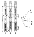
- FIG. 7 shows an example of the unfolding of a simplified frame in a network consisting of a central station and two mobile stations M1 and M2 (users).
- M2 is closest to the central station PA, the so-called temporal "calibration" phase and acquisition of the channel response (represented in FIG. 7 by the letters Q: question, R: response) is applied for the mobile M1 for example.
- the preamble P1 does not appear and all the channels broadcast by the central station to the mobile stations are grouped under the term "downward phase”.
- the representation of the duration of the CHAC phase has been exaggerated, its actual duration is much shorter.
- M1 and M2 have passed at least once already through the CHAC phase and that they both know the temporal "advance" to be applied to their transmission in the uplink phase.
- the advances respectively t1, t2 of the mobile stations M1, M2 are variable as a function of their distance from the central station. They are equal, for example, to twice the propagation time between the mobile station considered and the central station. This time t1, t2 is updated by the station after the mobile station has passed through the CHAC phase. It allows M1 and M2 to be correctly offset in time in the rising phase so that their pulses are perfectly interleaved when they arrive at the central station.
- the transit time measurements are made, for example, with a precision of 1 ns, which makes it possible to interleave with sufficient precision pulses of various origins every 10 ns.
- FIG. 8 represents an example of measurement known as of temporal "calibration" between the central station and each of the mobile stations, starting from the measurement of distance coupled with the acquisition of the response of the channel.
- the central station PA interrogates the three mobile stations M1, M2 and M3 in turn.
- the main objectives of this procedure are:
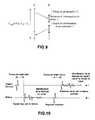
- FIG. 9 diagrammatically represents the course of the procedure, E represents the sender of the request (central station), R the receiver or mobile interrogated.
- the transmitter E transmits an interrogation sequence of duration Ti, Tp represents the time of propagation of this request to the receiver R and Tr the time of reversal and processing of the request by the receiver.
- Tp represents the time of propagation of this request to the receiver R and Tr the time of reversal and processing of the request by the receiver.
- the time required for the complete processing of the round trip procedure is equal to the round trip propagation time plus the turnaround time inside the mobile plus the length of the sequences transmitted on the one hand by the central station, on the other hand by the mobile station, (the turnaround time corresponds to time in the station questioned between reception of the signal and re-transmission of the response signal, classic in all equipment of the transponder type).
- This procedure is performed pulse by pulse or series of pulses by series of pulses.
- the access point emits its series of pulses, the mobile waits for the complete series and then transmits its own in return.
- the equalization of the uplink and the equalization of the downlink are different.
- Figure 11 shows schematically the principle of filtering and sampling at the input of the receiver.
- the structure of the receiver allowing to realize the equalization of the uplink and downlink propagation channel comprises for example a filter adapted to the received wave wrec (t) followed by a sampler at the "chip" rhythm Tc, that is to say at the rate of the interlaced pulses.
- the estimation of the channel parameters is done in a learning context in which a series of symbols known to the receivers is transmitted.
- C the spreading code coding matrix (used at the time spreading code level used for the different users) temporal
- H is the matrix (unknown) composed of the values of the impulse response h ( t ) of the channel, sampled at the rhythm T c (the response h (t) actually includes the convolution of the emission filter, the reception filter and the channel propagation).
- the samples of the impulse response of the channel having been estimated, the equalization consists in canceling all or part of the effect of the channel in order to recover the symbols transmitted.
- equalizers existing in the literature are applicable whether they are linear (EQMM, Zero Forcing (ZF), Rake, Adapted Filter, ...) or non-linear (Viterbi, DFE, ).
- the uplink is distinguished from the downlink by the fact that the central station sees the different users through different channels.
- Monitoring is for example carried out periodically in the CHAC following the designation of the terminal concerned by the access point (the master station) in the FCH. It is necessary to take into account the movement of the user or to compensate for variations in his environment (other people on the move, cars, ...)
- the central station may have to authorize only the mobile stations which have an impulse response, of the transmission channel between these stations and itself, particularly short.
- the time difference between the pulses transmitted by a mobile station can therefore be reduced, thus avoiding any equalization processing by the central station.
- This mode is useful when the number of mobile stations attached to the central station is large and the associated impulse responses are particularly complex.
- the central station can therefore be required to indicate the integration length to be used, namely the number of pulses per symbol (as a function of the link budget and therefore of the distance). We can thus nest different users with different integration parameters (different speeds, different priorities, ).
- the spectrum emitted by the base on the assumption of pulses transmitted regularly with a recurrence T, is composed of lines spaced 1 / T with an envelope in sin x / x. Under the same recurrence conditions, the spectrum is identical for the stations.
- the invention applies in particular whatever the choice of modulation for the pulses (PPM, bipolar, etc.) as well as the use or not of any integration factor. It is also possible to superimpose a code common to each user of a central point if one wishes to separate two adjacent networks, as in a cellular type structure.
Landscapes
- Engineering & Computer Science (AREA)
- Computer Networks & Wireless Communication (AREA)
- Signal Processing (AREA)
- Mobile Radio Communication Systems (AREA)
Applications Claiming Priority (2)
| Application Number | Priority Date | Filing Date | Title |
|---|---|---|---|
| FR0303304 | 2003-03-18 | ||
| FR0303304A FR2852763B1 (fr) | 2003-03-18 | 2003-03-18 | Procede et systeme de communication |
Publications (1)
| Publication Number | Publication Date |
|---|---|
| EP1460773A1 true EP1460773A1 (de) | 2004-09-22 |
Family
ID=32799682
Family Applications (1)
| Application Number | Title | Priority Date | Filing Date |
|---|---|---|---|
| EP04101036A Ceased EP1460773A1 (de) | 2003-03-18 | 2004-03-12 | UWB- Kommunikationsverfahren und Kommunikationssystem |
Country Status (3)
| Country | Link |
|---|---|
| US (1) | US6967945B2 (de) |
| EP (1) | EP1460773A1 (de) |
| FR (1) | FR2852763B1 (de) |
Cited By (2)
| Publication number | Priority date | Publication date | Assignee | Title |
|---|---|---|---|---|
| GB2410871A (en) * | 2004-02-03 | 2005-08-10 | Toshiba Res Europ Ltd | Time hopping code for ultra-wideband signals |
| US7505516B2 (en) | 2004-02-03 | 2009-03-17 | Kabushiki Kaisha Toshiba | Ultra wide band (UWB) synchronisation search |
Families Citing this family (5)
| Publication number | Priority date | Publication date | Assignee | Title |
|---|---|---|---|---|
| JP4602100B2 (ja) * | 2004-08-24 | 2010-12-22 | 富士通コンポーネント株式会社 | 通信装置 |
| US7499442B2 (en) * | 2004-11-30 | 2009-03-03 | Freescale Semiconductor, Inc. | Method for sharing bandwidth using reduced duty cycle signals |
| US20100124272A1 (en) * | 2008-11-19 | 2010-05-20 | Gene Fein | Coded pulse data transmission using a look-up table |
| WO2013085811A1 (en) * | 2011-12-06 | 2013-06-13 | Rambus Inc. | Receiver with enhanced isi mitigation |
| CN110703279B (zh) * | 2019-09-16 | 2021-12-07 | 西安空间无线电技术研究所 | 一种基于码片级脉冲跳时的卫星导航信号生成方法 |
Citations (2)
| Publication number | Priority date | Publication date | Assignee | Title |
|---|---|---|---|---|
| WO2002052740A1 (en) * | 2000-12-22 | 2002-07-04 | Scientific Generics Limited | Timing aid for ultra-wideband system |
| WO2003009608A2 (en) * | 2001-07-19 | 2003-01-30 | Roke Manor Research Limited | Method for synchronising radio terminals in a radio communication system |
Family Cites Families (3)
| Publication number | Priority date | Publication date | Assignee | Title |
|---|---|---|---|---|
| DE19747367C2 (de) * | 1997-10-27 | 2003-06-26 | Siemens Ag | Verfahren und Anordnung zur Übertragung von Daten über eine Funkschnittstelle in einem Funk-Kommunikationssystem |
| US7227852B2 (en) * | 2001-09-21 | 2007-06-05 | Sony Corporation | Wireless transmission system, wireless transmission method, wireless reception method, transmitting apparatus and receiving apparatus |
| US7609612B2 (en) * | 2002-07-12 | 2009-10-27 | Texas Instruments Incorporated | Multi-carrier transmitter for ultra-wideband (UWB) systems |
-
2003
- 2003-03-18 FR FR0303304A patent/FR2852763B1/fr not_active Expired - Fee Related
-
2004
- 2004-03-12 EP EP04101036A patent/EP1460773A1/de not_active Ceased
- 2004-03-16 US US10/801,040 patent/US6967945B2/en not_active Expired - Fee Related
Patent Citations (2)
| Publication number | Priority date | Publication date | Assignee | Title |
|---|---|---|---|---|
| WO2002052740A1 (en) * | 2000-12-22 | 2002-07-04 | Scientific Generics Limited | Timing aid for ultra-wideband system |
| WO2003009608A2 (en) * | 2001-07-19 | 2003-01-30 | Roke Manor Research Limited | Method for synchronising radio terminals in a radio communication system |
Non-Patent Citations (2)
| Title |
|---|
| Q. LI ET AL.: "Multiuser detection for DS-CDMA UWB in the home environment", IEEE JOURNAL ON SELECTED AREAS IN COMMUNICATIONS, vol. 20, no. 9, December 2002 (2002-12-01), pages 1701 - 1711, XP002260739 * |
| SOMAYAZULU V.S.; FOERSTER J.R.; ROY S.: "Design challenges for very high data rate UWB systems", CONFERENCE RECORD OF THE IEEE 36TH. ASILOMAR CONFERENCE ON SIGNALS, SYSTEMS, & COMPUTERS. PACIFIC GROOVE, CA, 3 November 2002 (2002-11-03), NEW YORK, pages 717 - 721, XP010638299 * |
Cited By (3)
| Publication number | Priority date | Publication date | Assignee | Title |
|---|---|---|---|---|
| GB2410871A (en) * | 2004-02-03 | 2005-08-10 | Toshiba Res Europ Ltd | Time hopping code for ultra-wideband signals |
| GB2410871B (en) * | 2004-02-03 | 2008-01-02 | Toshiba Res Europ Ltd | Ultra wide band (UWB) synchronisation search |
| US7505516B2 (en) | 2004-02-03 | 2009-03-17 | Kabushiki Kaisha Toshiba | Ultra wide band (UWB) synchronisation search |
Also Published As
| Publication number | Publication date |
|---|---|
| US6967945B2 (en) | 2005-11-22 |
| FR2852763B1 (fr) | 2005-06-03 |
| US20040184486A1 (en) | 2004-09-23 |
| FR2852763A1 (fr) | 2004-09-24 |
Similar Documents
| Publication | Publication Date | Title |
|---|---|---|
| EP0095959B1 (de) | Funkverbindungssystem nach dem Frequenzsprungverfahren | |
| EP0630120B1 (de) | Synchronisationsverfahren in Funktelefonkommunikationen mit Kodemultiplex-Vielfachzugriff | |
| EP0639010B1 (de) | Verfahren zur Auswahl aus mehreren Übertragungswegen auf denen Nachrichten empfangen werden in einer CDMA Funkanordnung | |
| EP1302016B1 (de) | Synchronisation der von mehreren einheiten ausgesendeten signale in einer basisstation, für fdma-kommunikationssysteme | |
| FR2737362A1 (fr) | Procede de selection des retards de propagation retenus pour recevoir des messages transmis par radiocommunication a etalement de spectre | |
| FR2713421A1 (fr) | Réseau local à transmission radio. | |
| FR2851384A1 (fr) | Procede de transmission de donnees radio, signal, systeme et dispositifs correspondant. | |
| EP0641096B1 (de) | Verfahren mit mehrfachem Zugang durch Einteilung in orthogonale Frequenzen, entsprechende zentrale Station, entfernte Station, System und deren Verwendung | |
| EP1460773A1 (de) | UWB- Kommunikationsverfahren und Kommunikationssystem | |
| CA2209476C (fr) | Procede de commutation d'un canal d'un premier chemin de propagation vers un second chemin de propagation | |
| FR2802369A1 (fr) | Procede de radiocommunication a multiplexage temporel, emetteur et recepteur pour la mise en oeuvre du procede | |
| Almonacid et al. | Throughput performance of time-and frequency-asynchronous ALOHA | |
| EP1179233B1 (de) | Verfahren zur funksignalverbreitung von einer radiokommunikation basisstation, basisstation und mobile endgeräte dafür | |
| CA2374339C (fr) | Procede de radiocommunication entre une station de base et des terminaux mobiles | |
| EP2879460B1 (de) | Knoten eines verbesserten Multibond-Ad-hoc-Radionetzes, und entsprechendes Verfahren | |
| EP0570273B1 (de) | Verfahren zur Entspreizung beim Empfang eines Breitbandsignals | |
| EP3641420B1 (de) | Funksynchronisierung für frequenzsprungsysteme | |
| WO2006069826A1 (fr) | Procede d'emission de signaux multiporteuses dans un reseau multicellulaire a macro-diversite planifiee, reseau, signal, procede et dispositif de reception correspondants. | |
| FR2823623A1 (fr) | Procede de transmission bidirectionnelle de signaux multiporteuses, systeme terminal de communication et signal correspondants | |
| EP1982429B1 (de) | Mehrfachzugangskommunikation auf der Basis einer Impuls-Ultrabreitband-Bitübertragungsschicht | |
| EP1075122A1 (de) | Messung der Stossantwort für einen vom Schlupffaktor abhängigen Pseudo-Zufallscode | |
| FR2934102A1 (fr) | Procede de synchronisation temporelle d'un signal numerique, dispositif et produit programme d'ordinateur correspondants | |
| EP0994580A1 (de) | Übertragungsverfahren in einem Funkkommunikationssystem mit Vielfachzugriff | |
| EP1573933A1 (de) | Verfahren und system zum empfangen eines ultrabreitbandsignals mit selbstanpassender anzahl von ausbreitungswegen | |
| FR2706232A1 (fr) | Paquet de signalisation pour un système de communication. |
Legal Events
| Date | Code | Title | Description |
|---|---|---|---|
| PUAI | Public reference made under article 153(3) epc to a published international application that has entered the european phase |
Free format text: ORIGINAL CODE: 0009012 |
|
| AK | Designated contracting states |
Kind code of ref document: A1 Designated state(s): AT BE BG CH CY CZ DE DK EE ES FI FR GB GR HU IE IT LI LU MC NL PL PT RO SE SI SK TR |
|
| AX | Request for extension of the european patent |
Extension state: AL LT LV MK |
|
| AKX | Designation fees paid | ||
| 17P | Request for examination filed |
Effective date: 20050125 |
|
| RBV | Designated contracting states (corrected) |
Designated state(s): AT BE BG CH CY CZ DE DK EE ES FI FR GB GR HU IE IT LI LU MC NL PL PT RO SE SI SK TR |
|
| REG | Reference to a national code |
Ref country code: DE Ref legal event code: 8566 |
|
| 17Q | First examination report despatched |
Effective date: 20050729 |
|
| STAA | Information on the status of an ep patent application or granted ep patent |
Free format text: STATUS: THE APPLICATION HAS BEEN REFUSED |
|
| 18R | Application refused |
Effective date: 20080107 |